EP4535941A1 - Apparatus for providing an electronic unit with clips for attachment to a panel - Google Patents
Apparatus for providing an electronic unit with clips for attachment to a panel Download PDFInfo
- Publication number
- EP4535941A1 EP4535941A1 EP24201595.6A EP24201595A EP4535941A1 EP 4535941 A1 EP4535941 A1 EP 4535941A1 EP 24201595 A EP24201595 A EP 24201595A EP 4535941 A1 EP4535941 A1 EP 4535941A1
- Authority
- EP
- European Patent Office
- Prior art keywords
- clips
- panel
- support
- housing
- clip
- Prior art date
- Legal status (The legal status is an assumption and is not a legal conclusion. Google has not performed a legal analysis and makes no representation as to the accuracy of the status listed.)
- Pending
Links
Images





Classifications
-
- H—ELECTRICITY
- H05—ELECTRIC TECHNIQUES NOT OTHERWISE PROVIDED FOR
- H05K—PRINTED CIRCUITS; CASINGS OR CONSTRUCTIONAL DETAILS OF ELECTRIC APPARATUS; MANUFACTURE OF ASSEMBLAGES OF ELECTRICAL COMPONENTS
- H05K5/00—Casings, cabinets or drawers for electric apparatus
- H05K5/0026—Casings, cabinets or drawers for electric apparatus provided with connectors and printed circuit boards [PCB], e.g. automotive electronic control units
- H05K5/0073—Casings, cabinets or drawers for electric apparatus provided with connectors and printed circuit boards [PCB], e.g. automotive electronic control units having specific features for mounting the housing on an external structure
-
- H—ELECTRICITY
- H05—ELECTRIC TECHNIQUES NOT OTHERWISE PROVIDED FOR
- H05K—PRINTED CIRCUITS; CASINGS OR CONSTRUCTIONAL DETAILS OF ELECTRIC APPARATUS; MANUFACTURE OF ASSEMBLAGES OF ELECTRICAL COMPONENTS
- H05K9/00—Screening of apparatus or components against electric or magnetic fields
- H05K9/0007—Casings
-
- H—ELECTRICITY
- H05—ELECTRIC TECHNIQUES NOT OTHERWISE PROVIDED FOR
- H05K—PRINTED CIRCUITS; CASINGS OR CONSTRUCTIONAL DETAILS OF ELECTRIC APPARATUS; MANUFACTURE OF ASSEMBLAGES OF ELECTRICAL COMPONENTS
- H05K7/00—Constructional details common to different types of electric apparatus
- H05K7/20—Modifications to facilitate cooling, ventilating, or heating
- H05K7/2039—Modifications to facilitate cooling, ventilating, or heating characterised by the heat transfer by conduction from the heat generating element to a dissipating body
- H05K7/20436—Inner thermal coupling elements in heat dissipating housings, e.g. protrusions or depressions integrally formed in the housing
- H05K7/2049—Pressing means used to urge contact, e.g. springs
-
- H—ELECTRICITY
- H05—ELECTRIC TECHNIQUES NOT OTHERWISE PROVIDED FOR
- H05K—PRINTED CIRCUITS; CASINGS OR CONSTRUCTIONAL DETAILS OF ELECTRIC APPARATUS; MANUFACTURE OF ASSEMBLAGES OF ELECTRICAL COMPONENTS
- H05K7/00—Constructional details common to different types of electric apparatus
- H05K7/20—Modifications to facilitate cooling, ventilating, or heating
- H05K7/20845—Modifications to facilitate cooling, ventilating, or heating for automotive electronic casings
- H05K7/20854—Heat transfer by conduction from internal heat source to heat radiating structure
Definitions
- Vehicle architecture and overall functionality have evolved over time and increased in complexity, thus requiring more advanced electronic capabilities. With that, comes a desire for finding innovative ways to house and secure electronic modules, for example, to vehicles so as to reduce the space occupied by the modules in the vehicle and also to protect and enhance overall module function.
- an apparatus may comprise an electronics unit including a plurality of electronics positioned therein that generate thermal energy.
- the electronics unit may further include a housing defining a plurality of openings positioned on a first side thereof, and a plurality of clips being attached to the housing, wherein a corresponding clip of the plurality of clips is positioned in a corresponding opening of the plurality of openings for attachment to the vehicle, and wherein the plurality of clips enables thermal energy to be transmitted from the electronics to a first portion of the vehicle.
- the apparatus may comprise an electronics unit including a plurality of electronics positioned therein that generate electromagnetic interference (EMI).
- the electronics unit may further include a housing defining a plurality of openings positioned on a first side thereof, and a plurality of clips being attached to the housing, wherein a corresponding clip of the plurality of clips is positioned in a corresponding opening of the plurality of opening for attachment to the vehicle, and wherein the plurality of clips mitigates the EMI, when the electronics unit is attached to the vehicle.
- EMI electromagnetic interference
- an electronics unit may comprise a plurality of electronics positioned therein that generate electromagnetic interference (EMI); a housing defining a plurality of openings positioned on a first side thereof; and a plurality of clips being attached to the housing, wherein a corresponding clip of the plurality of clips is positioned in a corresponding opening of the plurality of opening for attachment to the vehicle, and wherein the plurality of clips (i) enables thermal energy to be transmitted from the plurality of electronics to a first portion of the vehicle, and (ii) mitigates the EMI, when the electronics unit is attached to the vehicle.
- EMI electromagnetic interference
- the clips may hold or fix the electronic units to the panel.
- electronics units may include infotainment head units, instrument panel modules (or instrument panel control units), navigation modules (or navigation control units), audio control units, on-board charging devices, etc. It is recognized that the type of electronic unit that includes the disclosed clips may vary based on the desired criteria of a particular implementation. In general, the disclosed clips may be utilized in connection with any electronic unit that emits electromagnetic energy and thermal energy. Further, the disclosed clips may be arranged to fix the electronic unit of any size to one or more panels of the vehicle.
- the disclosed clip may be integrated into the housing of an electronics unit and may include a snap-fit feature, which may be easy to insert into the panel without requiring any additional tools.
- the housing may also be referred to as a "chassis".
- the housing or chassis may be formed as a single piece or as multiple parts that may be fitted together. Commonly, the housing or chassis may consist of two parts.
- the clips may be used where space is constrained and may include flexible (or spring like) tabs to provide a robust hold for mechanical retention on the panel.
- the clips may have a reduced overall footprint when compared to existing clips.
- the disclosed clips may temporarily hold the electronic unit to the panel while primary fasteners are used to further couple the electronic unit to the panel.
- the clips may additionally facilitate secure attachment of a unit to a panel while improving heat dissipation and providing EMI protection.
- Some implementations for various clips include one or more blades that bend in a particular orientation that may leave an opening of a housing of an electronic unit which exposes the unit to the environment. Such an opening allows dust or other particles to enter through the housing and come into contact with various electronics in the electronic unit which may degrade performance of the electronic unit.
- the clips described herein eliminate this opening, thus protecting the electronics in the unit from dust and other environmental particles or contaminants.
- FIG. 1 illustrates a bottom view of an electronics unit 100 that includes a plurality of clips 102a - 102d (or "102") as will be further described herein. While the electronics unit 100 generally includes a total of four clips (102a - 102d), it is recognized that the disclosed electronic unit 100 may include any number of clips 102. Each clip 102 may be formed of metal, etc.
- the electronics unit 100 generally includes a housing 101. In one example, the housing 101 may undergo die casting and be formed of metal. Further, the housing 101 may be formed of various non-ferrous metals such as, but not limited to, zinc, copper, aluminum, magnesium, lead, pewter, tin-based alloys, etc. The housing 101 may alternatively be formed of ferrous metals or plastics.
- the electronics unit may further include electronics 200 positioned in the electronics unit 100 that generate heat and are susceptible to generating electromagnetic interference. The electronics may be positioned within the housing 101.
- the housing 101 may include a plurality of recesses 107a - 107d ("107") on any side thereof.
- the recesses 107a - 107d may receive a corresponding clip 102a - 102d, respectively.
- Each clip 102 includes a base 103 having an aperture 104.
- a fastener (not shown) may be received by the aperture 104 to fasten the clip 102 to an outer surface of the housing 101.
- the fastener may be a clinch nut or other similar mechanism.
- the clips 102 may be formed without the aperture 104 and the fastener (not shown) may be driven into the clip 102 to secure the clip 102 to an outer surface of the housing 101.
- a clinch nut and screw may be used to secure the clip 102 to the housing 101.
- Each clip 102 further includes a support 105 that extends outwardly from the base 103.
- the support 105 and the base 103 may be formed on different planes from one another.
- each clip 102 includes a plurality of projections 108a - 108c ("108"). It is recognized that the number of projections 108 positioned on the housing 101 may vary based on the desired criteria of a particular implementation.
- the plurality of projections 108a - 108c extend outwardly away from the outer surface of the base 103 and/or the support 105 for insertion into the panel 106.
- the projection 108a extends outwardly from an end of the support 105 and is angled to extend toward the base 103, where an outer end of the projection 108a is positioned directly over the base 103.
- the projections 108b and 108c extend outwardly from an end of the base 103 and are angled to extend toward the support 105, where an outer end of the projections 108b and 108c are positioned directly over the support 105.
- Each of the projections 108 are spring-like and are configured to flex upon insertion to the panel.
- the projection 108a as positioned on the support 105 is offset from the position of the projections 108b and 108c on the support 105.
- the projection 108a is not positioned directly across from the projections 108b and 108c.
- the housing 101 of the electronics unit 100 may include a plurality of extensions 109a-109d ("109"). Each extension 109a- 109d may include an aperture 110a-110d ("110"), respectively.
- a fastener (not shown) may be received by the aperture 110 to fasten the electronics unit 100 to a panel 106 (not shown).
- the housing 101 may also be formed without extensions 109, and that the apertures 110 used for fastening the electronics unit 100 to a panel 106 may instead be formed on the main body of the housing 101 rather than on the extensions 109.
- the housing 101 further include a plurality of indexing pins 111a, 111b ("111") extending outward from the bottom surface of the housing 101 that may serve as a guide to align the electronics unit on a panel 106 (not shown).
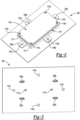
- Figure 2 illustrates a top view of an electronics unit 100 including the clips 102 according to an embodiment.
- the electronics unit 100 is shown aligned on a panel 106.
- the panel 106 may be of a shape and size suitable to receive the shape and size of an electronics unit 100 including the clips 102 according to various embodiments.
- the panel 106 may be formed of metal.
- the panel 106 may be formed of sheet metal.
- the panel 106 may be formed of plastic.
- the housing 101 may be die cast.
- the housing 101 may be formed by aluminum casting.
- the housing 101 may be formed as two parts, a top casing 112 and a bottom casing 113. The top 112 and bottom 113 casings may be formed separately and subsequently fitted together.
- the clips 102 may be fastened to the bottom casing 113 via a clinch fit mechanism.
- the top casing 112 may be fastened to the bottom casing 113 via a plurality of fasteners 114a-114d ("114").
- the top casing 112 may be fastened to the bottom casing 113 after the clips 102 have been fastened to the bottom casing 113, and after the electronics unit 100 has been fitted into the housing 101.
- the top casing 112 may be fastened to the bottom casing 113 via interference fit.
- Figure 3 illustrates a bottom view of the electronics unit 100 depicted in Figure 2 installed onto the panel 106.
- the projections 108a - 108d (“108") of the clips 102 protrude through the bottom of the panel 106.
- the outer ends of the projections 108 may compress inward upon insertion into the panel 106.
- the projections 108 may retract or spring back in response to being fully received into the panel 106, thereby retaining the clips 102 and thus the housing 101 fixed to the panel 106.
- the indexing pins 111a -111b extend outwardly from the bottom casing 113 (see Figure 2 ) through the panel 106.
- the pins 111 may serve as a guide to align the housing 101 on the panel 111.
- the clips 102 may then be inserted through the panel 106 so that the electronics unit 100 will be held in alignment on the panel 106.
- Fasteners (not shown) may then be inserted through the apertures 109 on the housing 101 and through apertures 115a - 115d ("115") on the panel 106.
- the apertures 115 on the panel 106 may be aligned with the apertures 109 on the bottom casing 113 of the housing 101.
- FIG 4 illustrates an example of a process by which the clips 102 may be installed into the bottom casing 113 of the housing 101 in accordance with one embodiment.
- the process may be a clinching process.
- a fastener (not shown) may be placed into the aperture 104 and drilled through the base 103 of the clip 102.
- the fastener may be a clinch nut or other similar mechanism.
- the clinch nut 116 may displace the material 117 around the aperture 104 on the base 103 of the clip 102 thereby causing the material 117 to flow into a recess 118 of the clinch nut 116 to hold the clinch nut 116 in place.
- the fastener may then be used to secure the clip 102 onto the bottom surface of the bottom casing 113 of an electronics unit 100.
- the clip 102 may be joined to the bottom casing 113 of the housing 101 by a rivet or by a screw.
- Figure 5 illustrates the clip 102 of Figures 1-3 , and an alternate embodiment of a clip 119 according to the disclosures herein.
- the thickness of the base 103 may be from 0.1 mm to 0.4 mm.
- the width of the base 103 may be from 7.5 mm to 11.5 mm.
- the width of the projections may be from 0.8 to 4.5 mm.
- the clip 102 depicted in Figure 5 has a base with a thickness of 0.3 mm and a width of 10.5 mm.
- the projection 108a has a width of 3.0 mm.
- the projections 108b, 108c have a width of 2.5 mm.
- the clip 119 has a base with a thickness of 0.3 mm and a width of 8.5 mm.
- the projection 108a has a width of 3.0 mm and the projections 108b, 108c have a width of 1.5 mm.
- the base 103 may have at least one aperture 104 through which a fastener may be inserted to fasten the clips 102/119 to a surface of the housing 101 of the module.
- the clip 102 is depicted with one aperture 104, whereas the clip 119 is depicted with five apertures.
- Figure 7 illustrates a method for installing an electronics unit 100 including clips 102 according to an embodiment onto the panel 106.
- an electronics unit 100 similar to that of Figure 6 is aligned onto the panel 106.
- the panel 106 is a vehicle panel 106.
- the indexing pins 111a, 111b and the clips 102 on the bottom surface of the bottom casing 113 are inserted through the vehicle panel 106 to secure the electronics unit 100 to the panel 106.
- Fasteners (not shown) may then be inserted through the apertures 110 in the housing 101 and the apertures 115 in the panel 106 to secure the electronics unit 100 to the panel 106.
- the electronics unit 100 may be removed from the panel 106.
- the electronics unit 100 may need to be removed from the panel 106 to perform repairs to the electronics unit 100.
- the fasteners inserted through the apertures 110 in the housing 101 and the apertures 115 in the panel may be removed.
- the clips 102 may be separated from the panel 106 by exerting a pulling force.
- the pulling force required to separate the clips 102 from the panel 106 may be between 30 and 50 newtons.
- the force required to pull the clips 102 from the panel 106 may be 30, or 35, or 40, or 45, or 50 newtons.
- the force required may vary depending on the materials of the clips 102, housing 101, and panel 106, as well as on the dimensions of the projections 108.
- Figure 9 illustrates a top view of the electronics unit 100 of Figure 8 installed on a panel 106.
- the apertures 110 on the extensions 109 of the bottom casing 113 are shown with fasteners 123.
- the fasteners 123 may be used to secure the electronics unit 100 to the panel 106.
- Figure 10 illustrates a bottom view of the electronics unit 100 of Figure 8 installed on a panel 106.
- the support 105 and the projections 108 of the clip 102 protrude through the panel 106.
- the indexing pins 111 and the fasteners 123 protrude through the panel to secure the electronics unit 100 to the panel 106.
- Figure 11 illustrates a side view of a portion of an electronics unit 100 including a clip 102 installed on a sheet metal panel 106 in accordance with one embodiment.
- the base 103 of the clip 102 is attached to the housing 101.
- the housing 101 is formed from die cast metal.
- the support 105 and the projections 108a and 108b protrude through the panel 106 to secure the electronics unit 100 to the panel 106.
- the outer ends of the projections 108 may compress inward upon insertion into the panel 106.
- the projections 108 may then retract or spring back in response to being fully received into the panel 106, thereby retaining the clips 102 and thus the housing 101 fixed to the panel 106.
- the projection 108a as positioned on the support 105 is offset from the position of the projections 108b and 108c on the support 105.
- Figure 13 illustrates a cross section view of a clip 102 attached to a housing 101 according to another embodiment.
- the housing 101 may be die-cast.
- a pair of projections 157a, 157b extend outwardly from a surface of the base 103 in a direction generally opposite that of the support 105.
- the projections 157a, 157b protrude through the housing 101 to attach the base 103 of the clip 102 to the housing 101 via an interference fit.
- the projections 157a, 157b include a first member 159a, 159b that extends outwardly from an end of the projection opposite to the base 103.
- the first member 159a, 159b is generally formed at an angle of roughly 45 degrees or less relative to an end of the projection 157a or 157b after attachment of the clip 102 into the housing 101.
- the housing 101 includes a recess 107for receiving the clip 102.
- the recess 107 includes a first ledge 161, a second ledge 163, and a tab 165.
- the tab 165 is positioned between the first ledge 161 and the second ledge 163.
- the first ledge 161 and one portion of the tab 165 define a first opening 167 for receiving the first projection 157a.
- the second ledge 163 and another portion of the tab 165 define a second opening 169 for receiving the second projection 157b.
- the first projection 157a is spring like and compresses against the first ledge 161 as the clip 102 is inserted into the housing 101.
- the second projection 157b is spring like and compresses against the second ledge 163 as the clip 102 is inserted into the housing 101.
- the first projection 157a and the second projection 157b spring outwardly past the first ledge 161 and the second ledge 163 (e.g., in opposite directions), where upper portions 171a, 171b of the first projection 157a and the second projection 157b abut an underside of the housing 101 to keep the clip 102 attached to the housing 101.
Landscapes
- Engineering & Computer Science (AREA)
- Microelectronics & Electronic Packaging (AREA)
- Physics & Mathematics (AREA)
- Thermal Sciences (AREA)
- Shielding Devices Or Components To Electric Or Magnetic Fields (AREA)
Abstract
An electronics unit including a plurality of electronics positioned therein that generate electromagnetic interference (EMI) and/or thermal energy. The electronics unit may include a housing defining a plurality of openings positioned on a first side thereof, and a plurality of clips attached to the housing. A corresponding clip of the plurality of clips is positioned in a corresponding opening of the plurality of opening for attachment to a vehicle. The plurality of clips enables thermal energy to be transmitted from the plurality of electronics to a first portion of the vehicle, and mitigates the EMI, when the electronics unit is attached to the vehicle.
Description
- Aspects disclosed herein generally relate to clips for use in establishing, inter alia, a mechanical hold and improving EMC and thermal contact for electronics units. These aspects and others will be discussed in more detail below.
- Vehicle architecture and overall functionality have evolved over time and increased in complexity, thus requiring more advanced electronic capabilities. With that, comes a desire for finding innovative ways to house and secure electronic modules, for example, to vehicles so as to reduce the space occupied by the modules in the vehicle and also to protect and enhance overall module function.
- In at least one aspect, an apparatus is provided. According to certain embodiments, the apparatus may comprise an electronics unit including a plurality of electronics positioned therein that generate thermal energy. The electronics unit may further include a housing defining a plurality of openings positioned on a first side thereof, and a plurality of clips being attached to the housing, wherein a corresponding clip of the plurality of clips is positioned in a corresponding opening of the plurality of openings for attachment to the vehicle, and wherein the plurality of clips enables thermal energy to be transmitted from the electronics to a first portion of the vehicle.
- In another aspect, an apparatus is provided. According to certain embodiments, the apparatus may comprise an electronics unit including a plurality of electronics positioned therein that generate electromagnetic interference (EMI). The electronics unit may further include a housing defining a plurality of openings positioned on a first side thereof, and a plurality of clips being attached to the housing, wherein a corresponding clip of the plurality of clips is positioned in a corresponding opening of the plurality of opening for attachment to the vehicle, and wherein the plurality of clips mitigates the EMI, when the electronics unit is attached to the vehicle.
- In another aspect, an electronics unit is provided. According to certain embodiments, the electronics unit may comprise a plurality of electronics positioned therein that generate electromagnetic interference (EMI); a housing defining a plurality of openings positioned on a first side thereof; and a plurality of clips being attached to the housing, wherein a corresponding clip of the plurality of clips is positioned in a corresponding opening of the plurality of opening for attachment to the vehicle, and wherein the plurality of clips (i) enables thermal energy to be transmitted from the plurality of electronics to a first portion of the vehicle, and (ii) mitigates the EMI, when the electronics unit is attached to the vehicle.
-
-
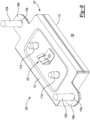
FIGURE 1 illustrates an electronics unit in accordance with one embodiment. -
FIGURE 2 illustrates a top view of an electronics unit fitted with the clips installed onto a sheet metal panel in accordance with one embodiment. -
FIGURE 3 illustrates a bottom view of the electronics unit ofFigure 2 installed onto the sheet metal panel in accordance with one embodiment. -
FIGURE 4 illustrates the riveting process used to install a clinch fastener into a clip in accordance with one embodiment. -
FIGURE 5 illustrates the metal clip ofFigures 1-3 , and a clip in accordance with one embodiment. -
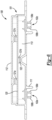
FIGURE 6 illustrates a cross-section view of an electronics unit fitted with the clips in accordance with one embodiment. -
FIGURE 7 illustrates a method for installing an electronics unit fitted with the clips onto a sheet metal panel in accordance with one embodiment. -
FIGURE 8 illustrates an alternate embodiment of an electronics unit fitted with the clip in accordance with one embodiment. -
FIGURE 9 illustrates a top view of the electronics unit ofFigure 8 installed on a sheet metal panel in accordance with one embodiment. -
FIGURE 10 illustrates a bottom view of the electronics unit ofFigure 8 installed on a sheet metal panel in accordance with one embodiment. -
FIGURE 11 illustrates a side view of a portion of an electronics unit with, for example, a die cast - based housing including a clip installed on a sheet metal panel in accordance with one embodiment. -
FIGURE 12 illustrates a side view of a portion of an electronics unit with a sheet metal-based housing including a clip installed on a sheet metal panel in accordance with one embodiment. -
FIGURE 13 illustrates a cross section view of an electronics unit with a die cast - based housing including a clip in accordance with one embodiment. - As required, detailed embodiments of the present invention are disclosed herein; however, it is to be understood that the disclosed embodiments are merely exemplary of the invention that may be embodied in various and alternative forms. The figures are not necessarily to scale; some features may be exaggerated or minimized to show details of particular components. Therefore, specific structural and functional details disclosed herein are not to be interpreted as limiting, but merely as a representative basis for teaching one skilled in the art to variously employ the present invention. It is recognized that one or more of the Figures may include reference to similar reference numerals and these reference numerals may be similar to one another unless otherwise stated. Similarly, if the reference numerals are introduced with one or more of the Figures, such reference numerals may not be referenced for other Figures where they appear if there is no change in their respective function and/or structure.
- Provided herein are clips for holding a unit in place on a panel so that fasteners may be tightened to secure the unit on the panel. In one example, the panel may be used in connection with panels that are utilized in a vehicle. The clips may be made of, for example, metal including but not limited to, steel sheet metal, etc. The clips may provide a spring and/or clamp-like function that couples any housing or body that are attached to the clips to the vehicle. In one example, an electronics-based module (or electronic unit) may include the disclosed clips. The clips may also provide robust electromagnetic compatibility (EMC) and thermal contact between the electronics-based module and the panel.
- As noted above, the clips may hold or fix the electronic units to the panel. Non-limiting examples of electronics units may include infotainment head units, instrument panel modules (or instrument panel control units), navigation modules (or navigation control units), audio control units, on-board charging devices, etc. It is recognized that the type of electronic unit that includes the disclosed clips may vary based on the desired criteria of a particular implementation. In general, the disclosed clips may be utilized in connection with any electronic unit that emits electromagnetic energy and thermal energy. Further, the disclosed clips may be arranged to fix the electronic unit of any size to one or more panels of the vehicle.
- In general, traditional electronic units without the use of clips may be difficult to mount to a panel based on gravity and/or the accessibility for the installer. Clips purchased from external suppliers may be bulky due to their attachment features and may not be cost effective. The disclosed clip may be integrated into the housing of an electronics unit and may include a snap-fit feature, which may be easy to insert into the panel without requiring any additional tools. The housing may also be referred to as a "chassis". The housing or chassis may be formed as a single piece or as multiple parts that may be fitted together. Commonly, the housing or chassis may consist of two parts. The clips may be used where space is constrained and may include flexible (or spring like) tabs to provide a robust hold for mechanical retention on the panel. The clips may have a reduced overall footprint when compared to existing clips. In addition, the disclosed clips may temporarily hold the electronic unit to the panel while primary fasteners are used to further couple the electronic unit to the panel. As noted above, the clips may additionally facilitate secure attachment of a unit to a panel while improving heat dissipation and providing EMI protection.
- Some implementations for various clips include one or more blades that bend in a particular orientation that may leave an opening of a housing of an electronic unit which exposes the unit to the environment. Such an opening allows dust or other particles to enter through the housing and come into contact with various electronics in the electronic unit which may degrade performance of the electronic unit. The clips described herein eliminate this opening, thus protecting the electronics in the unit from dust and other environmental particles or contaminants.
-
Figure 1 illustrates a bottom view of anelectronics unit 100 that includes a plurality ofclips 102a - 102d (or "102") as will be further described herein. While theelectronics unit 100 generally includes a total of four clips (102a - 102d), it is recognized that the disclosedelectronic unit 100 may include any number ofclips 102. Eachclip 102 may be formed of metal, etc. Theelectronics unit 100 generally includes ahousing 101. In one example, thehousing 101 may undergo die casting and be formed of metal. Further, thehousing 101 may be formed of various non-ferrous metals such as, but not limited to, zinc, copper, aluminum, magnesium, lead, pewter, tin-based alloys, etc. Thehousing 101 may alternatively be formed of ferrous metals or plastics. The electronics unit may further includeelectronics 200 positioned in theelectronics unit 100 that generate heat and are susceptible to generating electromagnetic interference. The electronics may be positioned within thehousing 101. - It is recognized that the
housing 101 may include a plurality ofrecesses 107a - 107d ("107") on any side thereof. Therecesses 107a - 107d may receive acorresponding clip 102a - 102d, respectively. Eachclip 102 includes a base 103 having anaperture 104. A fastener (not shown) may be received by theaperture 104 to fasten theclip 102 to an outer surface of thehousing 101. In one example, the fastener may be a clinch nut or other similar mechanism. Alternatively, theclips 102 may be formed without theaperture 104 and the fastener (not shown) may be driven into theclip 102 to secure theclip 102 to an outer surface of thehousing 101. In one example, a clinch nut and screw may be used to secure theclip 102 to thehousing 101. - Each
clip 102 further includes asupport 105 that extends outwardly from thebase 103. In general, thesupport 105 and the base 103 may be formed on different planes from one another. - As shown, each
clip 102 includes a plurality ofprojections 108a - 108c ("108"). It is recognized that the number of projections 108 positioned on thehousing 101 may vary based on the desired criteria of a particular implementation. The plurality ofprojections 108a - 108c extend outwardly away from the outer surface of thebase 103 and/or thesupport 105 for insertion into thepanel 106. For example, theprojection 108a extends outwardly from an end of thesupport 105 and is angled to extend toward thebase 103, where an outer end of theprojection 108a is positioned directly over thebase 103. Similarly, theprojections base 103 and are angled to extend toward thesupport 105, where an outer end of theprojections support 105. Each of the projections 108 are spring-like and are configured to flex upon insertion to the panel. As also shown, theprojection 108a as positioned on thesupport 105 is offset from the position of theprojections support 105. Thus, in this regard, theprojection 108a is not positioned directly across from theprojections - As shown, the
housing 101 of theelectronics unit 100 may include a plurality ofextensions 109a-109d ("109"). Eachextension 109a- 109d may include anaperture 110a-110d ("110"), respectively. A fastener (not shown) may be received by the aperture 110 to fasten theelectronics unit 100 to a panel 106 (not shown). It is recognized that thehousing 101 may also be formed without extensions 109, and that the apertures 110 used for fastening theelectronics unit 100 to apanel 106 may instead be formed on the main body of thehousing 101 rather than on the extensions 109. Thehousing 101 further include a plurality ofindexing pins housing 101 that may serve as a guide to align the electronics unit on a panel 106 (not shown). -
Figure 2 illustrates a top view of anelectronics unit 100 including theclips 102 according to an embodiment. Theelectronics unit 100 is shown aligned on apanel 106. Thepanel 106 may be of a shape and size suitable to receive the shape and size of anelectronics unit 100 including theclips 102 according to various embodiments. Additionally, thepanel 106 may be formed of metal. For example, thepanel 106 may be formed of sheet metal. Alternatively, thepanel 106 may be formed of plastic. As depicted, thehousing 101 may be die cast. For example, thehousing 101 may be formed by aluminum casting. As shown, thehousing 101 may be formed as two parts, atop casing 112 and abottom casing 113. The top 112 and bottom 113 casings may be formed separately and subsequently fitted together. Theclips 102 may be fastened to thebottom casing 113 via a clinch fit mechanism. Thetop casing 112 may be fastened to thebottom casing 113 via a plurality offasteners 114a-114d ("114"). Thetop casing 112 may be fastened to thebottom casing 113 after theclips 102 have been fastened to thebottom casing 113, and after theelectronics unit 100 has been fitted into thehousing 101. Alternatively, thetop casing 112 may be fastened to thebottom casing 113 via interference fit. - Referring still to
Figure 2 , thebottom casing 113 may include a plurality ofextensions 109a - 109d ("109") havingapertures 110a - 110d ("110"). The apertures 110 may receive fasteners (not shown) to fasten thebottom casing 113 to thepanel 106. -
Figure 3 illustrates a bottom view of theelectronics unit 100 depicted inFigure 2 installed onto thepanel 106. As shown, theprojections 108a - 108d ("108") of theclips 102 protrude through the bottom of thepanel 106. The outer ends of the projections 108 may compress inward upon insertion into thepanel 106. The projections 108 may retract or spring back in response to being fully received into thepanel 106, thereby retaining theclips 102 and thus thehousing 101 fixed to thepanel 106. Theindexing pins 111a -111b extend outwardly from the bottom casing 113 (seeFigure 2 ) through thepanel 106. Thepins 111 may serve as a guide to align thehousing 101 on thepanel 111. Theclips 102 may then be inserted through thepanel 106 so that theelectronics unit 100 will be held in alignment on thepanel 106. Fasteners (not shown) may then be inserted through the apertures 109 on thehousing 101 and throughapertures 115a - 115d ("115") on thepanel 106. The apertures 115 on thepanel 106 may be aligned with the apertures 109 on thebottom casing 113 of thehousing 101. -
Figure 4 illustrates an example of a process by which theclips 102 may be installed into thebottom casing 113 of thehousing 101 in accordance with one embodiment. The process may be a clinching process. In one example, a fastener (not shown) may be placed into theaperture 104 and drilled through thebase 103 of theclip 102. The fastener may be a clinch nut or other similar mechanism. As shown, when parallel pressure is applied to theclinch nut 116, theclinch nut 116 may displace thematerial 117 around theaperture 104 on thebase 103 of theclip 102 thereby causing thematerial 117 to flow into arecess 118 of theclinch nut 116 to hold theclinch nut 116 in place. The fastener may then be used to secure theclip 102 onto the bottom surface of thebottom casing 113 of anelectronics unit 100. Alternatively, theclip 102 may be joined to thebottom casing 113 of thehousing 101 by a rivet or by a screw. -
Figure 5 illustrates theclip 102 ofFigures 1-3 , and an alternate embodiment of aclip 119 according to the disclosures herein. The thickness of the base 103 may be from 0.1 mm to 0.4 mm. The width of the base 103 may be from 7.5 mm to 11.5 mm. The width of the projections may be from 0.8 to 4.5 mm. For example, theclip 102 depicted inFigure 5 has a base with a thickness of 0.3 mm and a width of 10.5 mm. Theprojection 108a has a width of 3.0 mm. Theprojections clip 119 has a base with a thickness of 0.3 mm and a width of 8.5 mm. Theprojection 108a has a width of 3.0 mm and theprojections aperture 104 through which a fastener may be inserted to fasten theclips 102/119 to a surface of thehousing 101 of the module. For example, theclip 102 is depicted with oneaperture 104, whereas theclip 119 is depicted with five apertures. - One or more of the
clips electronics unit 100 to apanel 106. It is recognized that the number ofclips clips particular electronics unit 100 for support. For example, a small light unit with little need for support may require only one clip. In the alternative, a larger heavier unit may require four, five, six, etc. clips. -
Figure 6 illustrates a cross-section view of anelectronics unit 100 includingclips 102 according to an embodiment. Theelectronics unit 100 includes atop casing 112 and abottom casing 113. Theelectronics unit 100 may further include a printed circuit board (PCB) 120 disposed between thetop casing 112 and thebottom casing 113. Theelectronics unit 100 may additionally include integrated circuits (IC) 121a - 121c ("121") in electronic communication with thePCB 120. The ICs 121 may be connected to the PCB via soldering, etc. Theelectronics unit 100 may also include a thermal interface orthermal gap fillers 122. Further, curing or non-curing fluid or viscous materials such as polymer-based materials, putty pads, viscoelastic, etc. may be used to form the thermal interface or thethermal gap fillers 122. It is recognized that the type and number of circuit boards and/or circuits may vary depending on the particular application. -
Figure 7 illustrates a method for installing anelectronics unit 100 includingclips 102 according to an embodiment onto thepanel 106. As depicted, anelectronics unit 100 similar to that ofFigure 6 is aligned onto thepanel 106. As shown, thepanel 106 is avehicle panel 106. The indexing pins 111a, 111b and theclips 102 on the bottom surface of thebottom casing 113 are inserted through thevehicle panel 106 to secure theelectronics unit 100 to thepanel 106. Fasteners (not shown) may then be inserted through the apertures 110 in thehousing 101 and the apertures 115 in thepanel 106 to secure theelectronics unit 100 to thepanel 106. - It is recognized that the
electronics unit 100 may be removed from thepanel 106. For example, theelectronics unit 100 may need to be removed from thepanel 106 to perform repairs to theelectronics unit 100. To remove theelectronics unit 100 from thepanel 106, the fasteners inserted through the apertures 110 in thehousing 101 and the apertures 115 in the panel may be removed. Next, theclips 102 may be separated from thepanel 106 by exerting a pulling force. The pulling force required to separate theclips 102 from thepanel 106 may be between 30 and 50 newtons. For example, the force required to pull theclips 102 from thepanel 106 may be 30, or 35, or 40, or 45, or 50 newtons. The force required may vary depending on the materials of theclips 102,housing 101, andpanel 106, as well as on the dimensions of the projections 108. -
Figure 8 illustrates a bottom view of anelectronics unit 100 including aclip 102 according to another embodiment. As shown, theelectronics unit 100 has ahousing 101. Thehousing 101 may have atop casing 112 and abottom casing 113. As depicted, thetop casing 112 and thebottom casing 113 are formed from sheet metal. Thebottom casing 113 may includeextensions aperture fasteners electronics unit 100 to apanel 106. Thebottom casing 113 of thehousing 101 may also includeindexing pins bottom casing 113. The indexing pins 111 may serve as a guide to align thehousing 101 on thepanel 106 as thefasteners electronics unit 100 to fix theelectronics unit 100 to thepanel 106. -
Figure 9 illustrates a top view of theelectronics unit 100 ofFigure 8 installed on apanel 106. The apertures 110 on the extensions 109 of thebottom casing 113 are shown with fasteners 123. The fasteners 123 may be used to secure theelectronics unit 100 to thepanel 106. -
Figure 10 illustrates a bottom view of theelectronics unit 100 ofFigure 8 installed on apanel 106. Thesupport 105 and the projections 108 of theclip 102 protrude through thepanel 106. In addition to thesupport 105 and projections 108 of theclip 102, the indexing pins 111 and the fasteners 123 protrude through the panel to secure theelectronics unit 100 to thepanel 106. -
Figure 11 illustrates a side view of a portion of anelectronics unit 100 including aclip 102 installed on asheet metal panel 106 in accordance with one embodiment. Thebase 103 of theclip 102 is attached to thehousing 101. In this case, thehousing 101 is formed from die cast metal. Thesupport 105 and theprojections panel 106 to secure theelectronics unit 100 to thepanel 106. The outer ends of the projections 108 may compress inward upon insertion into thepanel 106. The projections 108 may then retract or spring back in response to being fully received into thepanel 106, thereby retaining theclips 102 and thus thehousing 101 fixed to thepanel 106. While noted and shown in connection withFIGURE 1 but not fully shown inFIGURE 11 , theprojection 108a as positioned on thesupport 105 is offset from the position of theprojections support 105. - As shown, the
base 103 and thesupport 105 are generally formed at an angle of roughly 90 degrees relative to one another. Thehousing 101 generally defines anelongated channel 151 that may be formed on an outer portion thereof. Thebase 103 includes an extendingmember 153 for being received within theelongated channel 151 of thehousing 101. Thebase 103 and thus the extendingmember 153 is generally parallel to thepanel 106. The extendingmember 153 may be fixed within theelongated channel 151 to attach theclip 102 to thehousing 101. Theprojection 108a includes afirst member 155 that extends outwardly from thesupport 105. Thefirst member 155 is generally formed at an angle of roughly 45 degrees or less relative to thesupport 105 after full insertion of theclip 102 into thepanel 106. It may be desirable to maintain an angle of roughly 45 degrees or less with respect to thefirst member 155 and thesupport 105 to provide a smaller aperture within thepanel 106. - It is also recognized that the extending
member 153 of thebase 103 extends past thefirst member 155 of the projection 108 to ensure that thebase 103 is seated or completely fixed to thehousing 101. This also ensure that the base 103 remains coupled or attached to thehousing 101 in the event an operation attempts to separate theclip 102 from thehousing 101 in an attempt to remove theelectronics unit 100. It is recognized that in other embodiments thebase 103 may include an extendingmember 153 positioned on each side thereof to further aid in retaining theclip 102 to thehousing 101. In this instance, the extendingmember 153 may extend past thefirst member 155 of theprojection 108b. It is further recognized that each projection 108 may include thefirst member 155. -
Figure 12 illustrates a side view of a portion of anelectronics unit 100 including aclip 102 installed on asheet metal panel 106 in accordance with one embodiment. Thebase 103 of theclip 102 is attached to thehousing 101. As depicted, thehousing 101 is formed from sheet metal. Thesupport 105 and theprojections panel 106 to secure theelectronics unit 100 to thepanel 106. The outer ends of the projections 108 may compress inward upon insertion into thepanel 106. The projections 108 may retract or spring back in response to being fully received into thepanel 106, thereby retaining theclips 102 and thus thehousing 101 fixed to thepanel 106. -
Figure 13 illustrates a cross section view of aclip 102 attached to ahousing 101 according to another embodiment. In one example, thehousing 101 may be die-cast. A pair ofprojections support 105. Theprojections housing 101 to attach thebase 103 of theclip 102 to thehousing 101 via an interference fit. Theprojections first member base 103. Thefirst member projection clip 102 into thehousing 101. - The
housing 101 includes a recess 107for receiving theclip 102. In one example, therecess 107 includes afirst ledge 161, asecond ledge 163, and atab 165. Thetab 165 is positioned between thefirst ledge 161 and thesecond ledge 163. Thefirst ledge 161 and one portion of thetab 165 define afirst opening 167 for receiving thefirst projection 157a. Thesecond ledge 163 and another portion of thetab 165 define asecond opening 169 for receiving thesecond projection 157b. To couple theclip 102 to the recess 107 (or housing 101), thefirst projection 157a is spring like and compresses against thefirst ledge 161 as theclip 102 is inserted into thehousing 101. Similarly, thesecond projection 157b is spring like and compresses against thesecond ledge 163 as theclip 102 is inserted into thehousing 101. Once each of thefirst projection 157a and thesecond projection 157b are moved past thefirst ledge 161 and thesecond ledge 163, respectively, thefirst projection 157a and thesecond projection 157b spring outwardly past thefirst ledge 161 and the second ledge 163 (e.g., in opposite directions), whereupper portions first projection 157a and thesecond projection 157b abut an underside of thehousing 101 to keep theclip 102 attached to thehousing 101. - While exemplary embodiments are described above, it is not intended that these embodiments describe all possible forms of the invention. Rather, the words used in the specification are words of description rather than limitation, and it is understood that various changes may be made without departing from the spirit and scope of the invention. Additionally, the features of various implementing embodiments may be combined to form further embodiments of the invention.
Claims (15)
- An apparatus comprising:
an electronics unit including a plurality of electronics positioned therein that generate thermal energy, the electronics unit further including:a housing defining a plurality of openings positioned on a first side thereof; anda plurality of clips being attached to the housing, wherein a corresponding clip of the plurality of clips is positioned in a corresponding opening of the plurality of openings for attachment to a vehicle,wherein the plurality of clips enables thermal energy to be transmitted from the electronics to a first portion of the vehicle. - The apparatus of claim 1, wherein the plurality of clips, when attached to the first portion of the vehicle, reduce electromagnetic interference generated by the plurality of electronics.
- The apparatus of claim 1, wherein each clip includes at least one projection 108 that protrudes from the corresponding opening.
- The apparatus of claim 3, wherein each clip includes a base and a support, and wherein the support extends outwardly from the base.
- The apparatus of claim 4, wherein a first of the at least one projection extends outwardly from the support and is angled relative to the support, and a second of the at least one projection extends outwardly from the support 105 and is angled relative to the support.
- The apparatus of claim 5, wherein the at least one projection includes a first member that forms an angle of 45 degrees or less relative to the support when the clip is fully seated into the opening of a panel.
- The apparatus of claim 6, wherein the first projection as positioned on the support is offset from the second projection as positioned on the support.
- The apparatus of claim 6, wherein outer ends of the first projection and the second projection compress inward upon insertion into the panel and retract or spring back in response to being fully received into the panel, thereby retaining the plurality of clips and the housing fixed to the panel.
- The apparatus of claim 1, wherein the plurality of clips each has a width of about 7.5 mm to about 11.5 mm and a thickness of about 0.1 mm to about 0.4 mm.
- An apparatus comprising:
an electronics unit including a plurality of electronics positioned therein that generate electromagnetic interference (EMI), the electronics unit further including:a housing defining a plurality of openings positioned on a first side thereof; anda plurality of clips being attached to the housing, wherein a corresponding clip of the plurality of clips is positioned in a corresponding opening of the plurality of opening for attachment to a vehicle,wherein the plurality of clips mitigates the EMI, when the electronics unit is attached to the vehicle. - The apparatus of claim 10, wherein the plurality of electronics generate thermal energy, and wherein the plurality of clips enables the thermal energy to be transmitted from the electronics to a first portion of the vehicle.
- The apparatus of claim 10, wherein each clip includes at least one projection 108 that protrudes from the corresponding opening.
- The apparatus of claim 12, wherein each clip includes a base and a support, and wherein the support extends outwardly from the base.
- The apparatus of claim 13, wherein a first of the at least one projection extends outwardly from the support and is angled relative to the support, and a second of the at least one projection extends outwardly from the support and is angled relative to the support.
- The apparatus of claim 14, wherein the at least one projection includes a first member that forms an angle of 45 degrees or less relative to the support when the clip is fully seated into the opening of a panel.
Applications Claiming Priority (1)
| Application Number | Priority Date | Filing Date | Title |
|---|---|---|---|
| US18/480,449 US20250113469A1 (en) | 2023-10-03 | 2023-10-03 | Apparatus for providing an electronic unit with clips for attachment to a panel |
Publications (1)
| Publication Number | Publication Date |
|---|---|
| EP4535941A1 true EP4535941A1 (en) | 2025-04-09 |
Family
ID=92894788
Family Applications (1)
| Application Number | Title | Priority Date | Filing Date |
|---|---|---|---|
| EP24201595.6A Pending EP4535941A1 (en) | 2023-10-03 | 2024-09-20 | Apparatus for providing an electronic unit with clips for attachment to a panel |
Country Status (3)
| Country | Link |
|---|---|
| US (1) | US20250113469A1 (en) |
| EP (1) | EP4535941A1 (en) |
| CN (1) | CN119767584A (en) |
Citations (6)
| Publication number | Priority date | Publication date | Assignee | Title |
|---|---|---|---|---|
| JP2001078329A (en) * | 1999-09-02 | 2001-03-23 | Sumitomo Wiring Syst Ltd | Fitting structure for electrical connection box |
| EP1562296A2 (en) * | 2004-02-05 | 2005-08-10 | Hirschmann Electronics GmbH & Co. KG | Electronique equipment to be mounted to a part of a car |
| US20080310124A1 (en) * | 2007-06-15 | 2008-12-18 | Yijun Tu | Coupling arrangement for electronic device to a vehicle body |
| US20150062825A1 (en) * | 2013-08-28 | 2015-03-05 | Infineon Technologies Ag | Overmolded substrate-chip arrangement with heat sink |
| DE102013223552A1 (en) * | 2013-11-19 | 2015-05-21 | Robert Bosch Gmbh | Housing for a control electronics, method for mounting such a housing and control system for a vehicle |
| EP2916635B1 (en) * | 2012-11-02 | 2019-08-28 | Hitachi Automotive Systems, Ltd. | Electronic control device |
Family Cites Families (7)
| Publication number | Priority date | Publication date | Assignee | Title |
|---|---|---|---|---|
| JP3712982B2 (en) * | 2002-02-06 | 2005-11-02 | 株式会社ケーヒン | Electronic circuit board housing case |
| KR101477378B1 (en) * | 2013-03-21 | 2014-12-29 | 삼성전기주식회사 | Housing and power module having the same |
| DE102014212243A1 (en) * | 2014-06-25 | 2015-12-31 | Robert Bosch Gmbh | Device for controlling personal protection devices and method for producing a device for controlling personal protection devices |
| JPWO2017056727A1 (en) * | 2015-09-29 | 2018-02-22 | 日立オートモティブシステムズ株式会社 | Electronic control unit |
| DE102019114001A1 (en) * | 2019-05-24 | 2020-11-26 | Schaeffler Technologies AG & Co. KG | Power electronics unit with at least one semiconductor module connected by means of a plastic holder |
| US11523550B2 (en) * | 2019-10-08 | 2022-12-06 | Lear Corporation | Electrical assembly enclosure |
| KR20240058406A (en) * | 2022-10-26 | 2024-05-03 | 삼성전자주식회사 | Fastening member having integral structure and electric device having the fastening member having integral structure |
-
2023
- 2023-10-03 US US18/480,449 patent/US20250113469A1/en active Pending
-
2024
- 2024-09-20 EP EP24201595.6A patent/EP4535941A1/en active Pending
- 2024-09-26 CN CN202411349076.5A patent/CN119767584A/en active Pending
Patent Citations (6)
| Publication number | Priority date | Publication date | Assignee | Title |
|---|---|---|---|---|
| JP2001078329A (en) * | 1999-09-02 | 2001-03-23 | Sumitomo Wiring Syst Ltd | Fitting structure for electrical connection box |
| EP1562296A2 (en) * | 2004-02-05 | 2005-08-10 | Hirschmann Electronics GmbH & Co. KG | Electronique equipment to be mounted to a part of a car |
| US20080310124A1 (en) * | 2007-06-15 | 2008-12-18 | Yijun Tu | Coupling arrangement for electronic device to a vehicle body |
| EP2916635B1 (en) * | 2012-11-02 | 2019-08-28 | Hitachi Automotive Systems, Ltd. | Electronic control device |
| US20150062825A1 (en) * | 2013-08-28 | 2015-03-05 | Infineon Technologies Ag | Overmolded substrate-chip arrangement with heat sink |
| DE102013223552A1 (en) * | 2013-11-19 | 2015-05-21 | Robert Bosch Gmbh | Housing for a control electronics, method for mounting such a housing and control system for a vehicle |
Also Published As
| Publication number | Publication date |
|---|---|
| US20250113469A1 (en) | 2025-04-03 |
| CN119767584A (en) | 2025-04-04 |
Similar Documents
| Publication | Publication Date | Title |
|---|---|---|
| US20030016496A1 (en) | PCI riser card bracket assembly | |
| US7212411B2 (en) | Screwless clip mounted computer drive | |
| US6377445B1 (en) | Motherboard mounting assembly | |
| US6377447B1 (en) | Quick release disk drive to chassis mounting apparatus and method | |
| US5966289A (en) | Electronic device securement system | |
| US5757618A (en) | Expansion board mounting structure for computers | |
| US5999402A (en) | Heat sink fastener retention apparatus and method for computer systems | |
| CN101958291A (en) | Electronic control unit | |
| US5726859A (en) | Circuit board component retainer and extractor | |
| US6158594A (en) | Printed circuit board mounting bracket | |
| JP4844883B2 (en) | Electronic device and printed circuit board GND connection method | |
| US20250113469A1 (en) | Apparatus for providing an electronic unit with clips for attachment to a panel | |
| EP1152927A1 (en) | Air bag sensor module installation apparatus and method | |
| US6770813B1 (en) | Mountable microelectronic package | |
| US6381142B1 (en) | Electronic component comprising elastic members for fitting the component to body of target device | |
| US6264232B1 (en) | Air bag sensor module installation apparatus and method | |
| JP3264780B2 (en) | Circuit unit heat dissipation device | |
| JP3748733B2 (en) | Heat dissipation device for electronic equipment | |
| US20040012940A1 (en) | Fault-tolerant assembly of printed circuit board | |
| JP5448072B2 (en) | Electrical component mounting structure | |
| CN223598253U (en) | Vehicle event data recorder casing and vehicle event data recorder | |
| EP1916590A2 (en) | Panel holder | |
| JPH06188576A (en) | Mechanism for mounting electronic equipment | |
| JPS61179599A (en) | Holding of printed circuit board | |
| JP3107008U (en) | Member mounting structure |
Legal Events
| Date | Code | Title | Description |
|---|---|---|---|
| PUAI | Public reference made under article 153(3) epc to a published international application that has entered the european phase |
Free format text: ORIGINAL CODE: 0009012 |
|
| STAA | Information on the status of an ep patent application or granted ep patent |
Free format text: STATUS: THE APPLICATION HAS BEEN PUBLISHED |
|
| AK | Designated contracting states |
Kind code of ref document: A1 Designated state(s): AL AT BE BG CH CY CZ DE DK EE ES FI FR GB GR HR HU IE IS IT LI LT LU LV MC ME MK MT NL NO PL PT RO RS SE SI SK SM TR |
|
| STAA | Information on the status of an ep patent application or granted ep patent |
Free format text: STATUS: REQUEST FOR EXAMINATION WAS MADE |
|
| 17P | Request for examination filed |
Effective date: 20251009 |