EP4535936A1 - Jet soldering device - Google Patents
Jet soldering device Download PDFInfo
- Publication number
- EP4535936A1 EP4535936A1 EP23823866.1A EP23823866A EP4535936A1 EP 4535936 A1 EP4535936 A1 EP 4535936A1 EP 23823866 A EP23823866 A EP 23823866A EP 4535936 A1 EP4535936 A1 EP 4535936A1
- Authority
- EP
- European Patent Office
- Prior art keywords
- solder
- conveyance
- abutment body
- substrate
- claws
- Prior art date
- Legal status (The legal status is an assumption and is not a legal conclusion. Google has not performed a legal analysis and makes no representation as to the accuracy of the status listed.)
- Pending
Links
Images




Classifications
-
- B—PERFORMING OPERATIONS; TRANSPORTING
- B23—MACHINE TOOLS; METAL-WORKING NOT OTHERWISE PROVIDED FOR
- B23K—SOLDERING OR UNSOLDERING; WELDING; CLADDING OR PLATING BY SOLDERING OR WELDING; CUTTING BY APPLYING HEAT LOCALLY, e.g. FLAME CUTTING; WORKING BY LASER BEAM
- B23K3/00—Tools, devices or special appurtenances for soldering, e.g. brazing, or unsoldering, not specially adapted for particular methods
- B23K3/02—Soldering irons; Bits
- B23K3/029—Solder or residue removing devices
-
- B—PERFORMING OPERATIONS; TRANSPORTING
- B23—MACHINE TOOLS; METAL-WORKING NOT OTHERWISE PROVIDED FOR
- B23K—SOLDERING OR UNSOLDERING; WELDING; CLADDING OR PLATING BY SOLDERING OR WELDING; CUTTING BY APPLYING HEAT LOCALLY, e.g. FLAME CUTTING; WORKING BY LASER BEAM
- B23K3/00—Tools, devices or special appurtenances for soldering, e.g. brazing, or unsoldering, not specially adapted for particular methods
- B23K3/08—Auxiliary devices therefor
-
- B—PERFORMING OPERATIONS; TRANSPORTING
- B08—CLEANING
- B08B—CLEANING IN GENERAL; PREVENTION OF FOULING IN GENERAL
- B08B1/00—Cleaning by methods involving the use of tools
- B08B1/10—Cleaning by methods involving the use of tools characterised by the type of cleaning tool
- B08B1/12—Brushes
-
- B—PERFORMING OPERATIONS; TRANSPORTING
- B08—CLEANING
- B08B—CLEANING IN GENERAL; PREVENTION OF FOULING IN GENERAL
- B08B1/00—Cleaning by methods involving the use of tools
- B08B1/10—Cleaning by methods involving the use of tools characterised by the type of cleaning tool
- B08B1/16—Rigid blades, e.g. scrapers; Flexible blades, e.g. wipers
- B08B1/165—Scrapers
-
- B—PERFORMING OPERATIONS; TRANSPORTING
- B08—CLEANING
- B08B—CLEANING IN GENERAL; PREVENTION OF FOULING IN GENERAL
- B08B1/00—Cleaning by methods involving the use of tools
- B08B1/20—Cleaning of moving articles, e.g. of moving webs or of objects on a conveyor
-
- B—PERFORMING OPERATIONS; TRANSPORTING
- B23—MACHINE TOOLS; METAL-WORKING NOT OTHERWISE PROVIDED FOR
- B23K—SOLDERING OR UNSOLDERING; WELDING; CLADDING OR PLATING BY SOLDERING OR WELDING; CUTTING BY APPLYING HEAT LOCALLY, e.g. FLAME CUTTING; WORKING BY LASER BEAM
- B23K1/00—Soldering, e.g. brazing, or unsoldering
- B23K1/0008—Soldering, e.g. brazing, or unsoldering specially adapted for particular articles or work
- B23K1/0016—Soldering of electronic components
-
- B—PERFORMING OPERATIONS; TRANSPORTING
- B23—MACHINE TOOLS; METAL-WORKING NOT OTHERWISE PROVIDED FOR
- B23K—SOLDERING OR UNSOLDERING; WELDING; CLADDING OR PLATING BY SOLDERING OR WELDING; CUTTING BY APPLYING HEAT LOCALLY, e.g. FLAME CUTTING; WORKING BY LASER BEAM
- B23K1/00—Soldering, e.g. brazing, or unsoldering
- B23K1/018—Unsoldering; Removal of melted solder or other residues
-
- B—PERFORMING OPERATIONS; TRANSPORTING
- B23—MACHINE TOOLS; METAL-WORKING NOT OTHERWISE PROVIDED FOR
- B23K—SOLDERING OR UNSOLDERING; WELDING; CLADDING OR PLATING BY SOLDERING OR WELDING; CUTTING BY APPLYING HEAT LOCALLY, e.g. FLAME CUTTING; WORKING BY LASER BEAM
- B23K1/00—Soldering, e.g. brazing, or unsoldering
- B23K1/08—Soldering by means of dipping in molten solder
- B23K1/085—Wave soldering
-
- B—PERFORMING OPERATIONS; TRANSPORTING
- B23—MACHINE TOOLS; METAL-WORKING NOT OTHERWISE PROVIDED FOR
- B23K—SOLDERING OR UNSOLDERING; WELDING; CLADDING OR PLATING BY SOLDERING OR WELDING; CUTTING BY APPLYING HEAT LOCALLY, e.g. FLAME CUTTING; WORKING BY LASER BEAM
- B23K3/00—Tools, devices or special appurtenances for soldering, e.g. brazing, or unsoldering, not specially adapted for particular methods
- B23K3/06—Solder feeding devices; Solder melting pans
- B23K3/0646—Solder baths
- B23K3/0653—Solder baths with wave generating means, e.g. nozzles, jets, fountains
-
- B—PERFORMING OPERATIONS; TRANSPORTING
- B23—MACHINE TOOLS; METAL-WORKING NOT OTHERWISE PROVIDED FOR
- B23K—SOLDERING OR UNSOLDERING; WELDING; CLADDING OR PLATING BY SOLDERING OR WELDING; CUTTING BY APPLYING HEAT LOCALLY, e.g. FLAME CUTTING; WORKING BY LASER BEAM
- B23K3/00—Tools, devices or special appurtenances for soldering, e.g. brazing, or unsoldering, not specially adapted for particular methods
- B23K3/08—Auxiliary devices therefor
- B23K3/082—Flux dispensers; Apparatus for applying flux
-
- B—PERFORMING OPERATIONS; TRANSPORTING
- B23—MACHINE TOOLS; METAL-WORKING NOT OTHERWISE PROVIDED FOR
- B23K—SOLDERING OR UNSOLDERING; WELDING; CLADDING OR PLATING BY SOLDERING OR WELDING; CUTTING BY APPLYING HEAT LOCALLY, e.g. FLAME CUTTING; WORKING BY LASER BEAM
- B23K3/00—Tools, devices or special appurtenances for soldering, e.g. brazing, or unsoldering, not specially adapted for particular methods
- B23K3/08—Auxiliary devices therefor
- B23K3/085—Cooling, heat sink or heat shielding means
-
- H—ELECTRICITY
- H05—ELECTRIC TECHNIQUES NOT OTHERWISE PROVIDED FOR
- H05K—PRINTED CIRCUITS; CASINGS OR CONSTRUCTIONAL DETAILS OF ELECTRIC APPARATUS; MANUFACTURE OF ASSEMBLAGES OF ELECTRICAL COMPONENTS
- H05K3/00—Apparatus or processes for manufacturing printed circuits
- H05K3/30—Assembling printed circuits with electric components, e.g. with resistors
- H05K3/32—Assembling printed circuits with electric components, e.g. with resistors electrically connecting electric components or wires to printed circuits
- H05K3/34—Assembling printed circuits with electric components, e.g. with resistors electrically connecting electric components or wires to printed circuits by soldering
-
- B—PERFORMING OPERATIONS; TRANSPORTING
- B23—MACHINE TOOLS; METAL-WORKING NOT OTHERWISE PROVIDED FOR
- B23K—SOLDERING OR UNSOLDERING; WELDING; CLADDING OR PLATING BY SOLDERING OR WELDING; CUTTING BY APPLYING HEAT LOCALLY, e.g. FLAME CUTTING; WORKING BY LASER BEAM
- B23K2101/00—Articles made by soldering, welding or cutting
- B23K2101/36—Electric or electronic devices
- B23K2101/42—Printed circuits
-
- H—ELECTRICITY
- H05—ELECTRIC TECHNIQUES NOT OTHERWISE PROVIDED FOR
- H05K—PRINTED CIRCUITS; CASINGS OR CONSTRUCTIONAL DETAILS OF ELECTRIC APPARATUS; MANUFACTURE OF ASSEMBLAGES OF ELECTRICAL COMPONENTS
- H05K2203/00—Indexing scheme relating to apparatus or processes for manufacturing printed circuits covered by H05K3/00
- H05K2203/04—Soldering or other types of metallurgic bonding
- H05K2203/044—Solder dip coating, i.e. coating printed conductors, e.g. pads by dipping in molten solder or by wave soldering
-
- H—ELECTRICITY
- H05—ELECTRIC TECHNIQUES NOT OTHERWISE PROVIDED FOR
- H05K—PRINTED CIRCUITS; CASINGS OR CONSTRUCTIONAL DETAILS OF ELECTRIC APPARATUS; MANUFACTURE OF ASSEMBLAGES OF ELECTRICAL COMPONENTS
- H05K3/00—Apparatus or processes for manufacturing printed circuits
- H05K3/30—Assembling printed circuits with electric components, e.g. with resistors
- H05K3/32—Assembling printed circuits with electric components, e.g. with resistors electrically connecting electric components or wires to printed circuits
- H05K3/34—Assembling printed circuits with electric components, e.g. with resistors electrically connecting electric components or wires to printed circuits by soldering
- H05K3/3465—Application of solder
- H05K3/3468—Application of molten solder, e.g. dip soldering
Definitions
- the present invention relates to a jet soldering apparatus that supplies molten solder to a substrate.
- a plurality of conveyance claws for conveying a substrate has been used in a soldering apparatus such as a jet soldering apparatus.
- Molten solder jetted during soldering may be applied to the conveyance claws, the molten solder may solidify while being attached to the conveyance claws, and the solder may adhere to the conveyance claws, and thus, removal of the solder adhering to the conveyance claws has been performed in related art.
- JP 2002-190666 A discloses an aspect in which solder adhering to conveyance claws is removed by a removal brush as an example in related art and proposes an aspect in which the solder is removed by hot air supplied from a blowing nozzle.
- solder composition to be used in the jet soldering apparatus
- adhesive force of solder is strong, and the solder adhering to a conveyance claws may not be removed by a removal brush in related art or hot air supplied from a blowing nozzle.
- the present invention provides a solder removing mechanism for more reliably removing solder attached to conveyance claws.
- a solder removing mechanism is a solder removing mechanism for removing solder from conveyance claws for conveying a substrate to which the solder is supplied, the solder removing may comprise an abutment body that can relatively pass through recesses of the conveyance claws or below the conveyance claws.
- the abutment body may have a first abutment body that can relatively pass through the recesses of the conveyance claws, and a second abutment body that can relatively pass under the conveyance claws.
- the solder removing mechanism according to concept 1 or 2 may comprise a brush positioned on a downstream side of the abutment body in a conveyance direction of the conveyance claws.
- solder removing mechanism In the solder removing mechanism according to any one of concepts 1 to 3, wherein the abutment body is an abutment plate.
- the abutment body has a bent part, and a distal end part that extends from the bent part toward a downstream side in a moving direction of the conveyance claws.
- the solder removing mechanism according to any one of concepts 1 to 5 may comprise a guide part that elongates below the abutment body and that guides the solder falling from the conveyance claws to a storage tank.
- the solder removing mechanism according to any one of concepts 1 to 6 may comprise a cover that is provided on an upstream side of the abutment body in a moving direction of the conveyance claws and that extends in a vertical direction.
- solder removing mechanism for more reliably removing solder attached to conveyance claws can be provided.
- a soldering apparatus illustrated in Fig. 1 is an apparatus that performs soldering processing on a substrate 200 on which electronic components such as semiconductor elements, resistors, and capacitors are mounted on a circuit. Typically, the electronic components and the like are positioned on a lower side of the substrate 200.
- the soldering apparatus has a main body 1 and a conveyance unit 5 that conveys the substrate 200.
- the main body 1 has a carry-in port 2 through which the substrate 200 is carried in and a carry-out port 3 through which the substrate 200 is carried out.
- the substrate 200 may be conveyed at a predetermined angle, for example, an inclination of about 3 to 6 degrees when viewed from the side (see Figs. 7 and 8 ).
- a conveyance unit 5 may have a conveyance rail 6 (see Fig. 7 ), conveyance claws 510 (see Fig. 2 ) movable along the conveyance rail 6 in a state of gripping a substrate 200, and a conveyance drive unit (not illustrated) that applies driving force for moving the conveyance claws 510 along the conveyance rail 6.
- the conveyance rail 6 aluminum, iron, stainless steel, or the like, may be used.
- the conveyance claw 510 has a recess 511 for gripping the substrate 200 (see Fig. 2 ).
- the main body 1 may be provided with a fluxer 10 for applying flux to the substrate 200, a preheater unit 15 for preheating the substrate 200 coated with flux, a jet soldering apparatus 100 for jetting molten solder into contact with the substrate 200, and a cooler 20 for cooling the soldered substrate 200.
- the substrate 200 conveyed along the conveyance rail 6 of the conveyance unit 5 sequentially passes through the fluxer 10, the preheater unit 15, the jet soldering apparatus 100, and the cooler 20.
- the soldering apparatus is illustrated in an upper plan view except for the control unit 50, the storage unit 60, and an operation unit 70 described later.
- the fluxer 10 is used to apply flux to the conveyed substrate 200.
- the flux may include a solvent, an activator, and the like.
- the fluxer 10 may be provided with a plurality of coating apparatuses.
- the type of flux may be selectively used according to the type of solder and the type of the substrate 200.
- the preheater unit 15 heats the substrate 200 to uniformly raise the substrate 200 to a predetermined temperature.
- a halogen heater is used as the preheater unit 15.
- the halogen heater can rapidly heat the substrate 200 to a set temperature.
- the substrate 200 may be heated by blowing gas (hot air) heated by the heater onto the substrate 200 by a fan.
- a farinfrared panel heater or the like may be used as the preheater unit 15.
- the cooler 20 has a cooling fan which is not illustrated, and cools the substrate 200 soldered by the jet soldering apparatus 100.
- the control of the cooling fan may be only ON and OFF, but the wind speed may be adjusted.
- a chiller or the like may be used to cool the substrate 200 to a predetermined temperature.
- the control unit 50 illustrated in Fig. 1 is communicably connected to the conveyance unit 5, the fluxer 10, the preheater unit 15, the jet soldering apparatus 100, the cooler 20, the operation unit 70, and the storage unit 60.
- the communicable connections include both wired and wireless connections.
- the operation unit 70 may have a liquid crystal display panel, a numeric keypad, or the like, and is typically a personal computer, a smartphone, a tablet, a touch panel or the like.
- the control unit 50 may control a conveyance speed by the conveyance unit 5, a timing of conveying the substrate 200, a temperature of the flux at the fluxer 10, an application amount of the flux, a temperature of the preheater unit 15, a temperature of molten solder S of the jet soldering apparatus 100, a jet amount, a jet speed, ON and OFF of the cooling fan of the cooler 20, and the like.
- the storage unit 60 may store information input by the operation unit 70, an instruction of the control unit 50, an operating time of the jet soldering apparatus 100, and the like.
- the conveyance speed of the substrate 200 is about 1 to 3 cm per second for example.
- the conveyance claws 510 are moved along the conveyance rail 6, whereby the substrate 200 is conveyed.
- the substrate 200 is carried into a main body 1 from a carry-in port 2.
- the fluxer 10 applies flux to a predetermined portion of the substrate 200.
- the conveyance claws 510 convey the substrate 200 to which the flux has been applied by the fluxer 10 to a preheater unit 15.
- the preheater unit 15 heats the substrate 200 to a predetermined temperature.
- the conveyance claws 510 convey the substrate 200 heated to the predetermined temperature by the preheater unit 15 to a jet soldering apparatus 100.
- the jet soldering apparatus 100 solders a predetermined portion of the substrate 200. While the jet soldering apparatus 100 is supplying molten solder S, the molten solder S supplied from a first supply port 125 and the molten solder S supplied from a second supply port 135 are mixed, and the molten solder S is supplied to above the conveyance rail 6.
- the molten solder S is configured not to be separated from the substrate 200 conveyed by the conveyance claws 510 between the first supply port 125 and the second supply port 135.
- the molten solder S supplied from the first supply port 125 pushes up the molten solder S supplied from the second supply port 135, and a plurality of convex shapes corresponding to first openings 126 are formed by the molten solder S.
- the conveyance claws 510 convey the soldered substrate 200 to a cooler 20.
- a cooling fan of the cooler 20 cools the soldered substrate 200 for a predetermined period.
- the conveyance claws 510 discharge the substrate 200 from a carry-out port 3, soldering treatment to the substrate 200 is completed.
- a conveyance direction A of the substrate faces an opposite direction of a conveyance direction B of the conveyance claws 510 (see Fig. 1 ).
- the conveyance claws 510 pass through a solder removing mechanism 520.
- the solder adhering to the conveyance claws 510 is removed by the solder removing mechanism 520.
- a pair of solder removing mechanisms 520 is provided so that the solder attached to each of the conveyance claws 510 gripping the substrate 200 can be removed.
- the conveyance claws 510 When the conveyance claws 510 that have passed through the solder removing mechanism 520 return to the carry-in port 2, the conveyance claws 510 convey another substrate 200.
- a large number of the plurality of conveyance claws 510 are arranged along the conveyance rail 6, and the substrate 200 is sequentially conveyed by the plurality of conveyance claws 510 which are parts of a large number of conveyance rails 6.
- the jet soldering apparatus 100 may have a storage tank 110 for storing the molten solder S, and a supply port for supplying the molten solder S to the substrate 200.
- the supply port may have two types of the first supply port 125 and the second supply port 135. Then, the molten solder S may be jetted from the first supply port 125 by receiving driving force from a first pump 141 that is a first drive unit, and the molten solder S may be jetted from the second supply port 135 by receiving driving force from a second pump 146 that is a second drive unit.
- the molten solder S jetted from the first supply port 125 and the second supply port 135 is jetted upward from below.
- the molten solder S having received the driving force from the first pump 141 is pressure-fed in a duct and jetted toward the substrate 200 to attach the solder to a predetermined portion of the substrate 200.
- the molten solder S having received the driving force from the second pump 146 is pressure-fed in a duct and jetted toward the substrate 200 to attach the solder to a predetermined portion of the substrate 200.
- the first supply port 125 of the jet soldering apparatus 100 has a plurality of first openings 126, and the first openings 126 constitute a primary jet nozzle.
- the plurality of first openings 126 are used to vigorously supply a large amount of molten solder S to the substrate 200.
- a second opening 136 of the second supply port 135 is a secondary jet nozzle, and is used to supply the molten solder S to the substrate 200 with weaker force than the first supply port 125.
- the jet solder supplied from the first supply port 125 is a dynamic supply for vigorously colliding the molten solder S against the substrate 200, and is a supply for spreading the molten solder S to every corner of the substrate 200.
- the jet solder supplied from the second supply port 135 is a static supply, and is a supply for cleanly attaching the solder to an electrode or the like of the substrate 200 by passing the jet solder through the molten solder S having a gentle flow.
- the configuration of the jet soldering apparatus and conditions such as a force of the jet of the molten solder are examples, and the present application is not limited to the above configuration.
- a first supply unit 120 has a first housing 121 and the first supply port 125 provided on an upper surface of the first housing 121 and having one or the plurality of first openings 126 for supplying the molten solder S.
- the first opening 126 may be provided so as to protrude upward from the upper surface of the first housing 121.
- a second supply unit 130 has a second housing 131 and the second supply port 135 provided on an upper surface of the second housing 131 and having one or a plurality of the second openings 136 for supplying the molten solder S.
- the first housing 121 and the second housing 131 may be provided apart from each other (see Fig. 7 ), but they may be provided integrally (see Fig. 8 ). In a case where the first housing 121 and the second housing 131 are integrated, a part of the wall surface may be shared.
- An aspect may be adopted in which no opening or gap through which the molten solder S falls downward is provided between the first supply port 125 and the second supply port 135 on an upper surface of the first housing 121 and the second housing 131 along the substrate conveyance direction A.
- a surface area where the molten solder S comes into contact with oxygen increases, and an oxide is generated.
- the molten solder S does not fall between the first supply port 125 and the second supply port 135 along the substrate conveyance direction A, so that generation of an oxide of the molten solder S can be prevented.
- the solder removing mechanism 520 of the present embodiment has an abutment body 530 that can relatively pass through recesses 511 of the moving conveyance claws 510 or below the moving conveyance claws 510 after the substrate 200 is removed from the conveyance claws 510 and conveyed.
- the conveyance claws 510 gripping the substrate 200 move toward a front surface side of a paper surface, but the conveyance claws 510 not gripping the substrate 200 illustrated on the left and right sides of Fig. 2 move toward a back surface side of the paper surface.
- "can pass" means can relatively pass.
- the conveyance claws 510 move and the abutment body 530 is stopped, the conveyance claws 510 pass through the abutment body 530, so that the abutment body 530 relatively passes through the recesses 511 of the moving conveyance claws 510 or below the moving conveyance claws 510.
- the abutment body 530 abuts on the cured solder attached to the conveyance claws 510 to remove the solder.
- the solder attached to the conveyance claws 510 and cured can be more reliably scraped off.
- the solder firmly attached to the conveyance claws 510 may not be scraped off.
- the abutment body 530 as in the present embodiment, it is possible to prevent occurrence of such a situation.
- solder such as Sn-58Bi (Bi: 58 mass%, remaining part: Sn)
- the solder tends to firmly adhere to the conveyance claws 510, and thus it is advantageous to provide the abutment body 530 as in the present embodiment.
- adhesive force of Sn-Bi solder such as Sn-58Bi is much stronger than an SAC (Sn-Ag-Cu) composition, and a brush 590 in the related art may not remove the adhered solder.
- Sn-Bi solder having strong adhesion force can be more reliably scraped off.
- an amount of the Sn-Bi solder attached to the conveyance claws 510 is larger than that of the SAC composition, and thus, an amount of solder to be scraped off is larger.
- an amount of solder to be scraped off is larger.
- the brush 590 in the related art is adopted, clogging, or the like, is also concerned.
- the solder having strong adhesion force is not limited to the Sn-Bi solder, and the present embodiment can exhibit the effect even in another solder composition having strong adhesion force such as the Sn-Sb solder.
- a pair of the conveyance claws 510 sandwiching the substrate 200 is provided, and thus, a pair of abutment bodies 530 may also be provided.
- at least part of the solder removing mechanism 520 may be located above the storage tank 110 of the jet solder apparatus.
- the conveyance claw 510 may be made of resin or metal, and when made of metal, may be made of stainless steel such as SUS.
- the abutment body 530 may have a first abutment body 540 that can relatively pass through the recesses 511 of the moving conveyance claws 510 and can abut on the cured solder attached to the recesses 511 of the conveyance claws 510, and a second abutment body 550 that can relatively pass under the moving conveyance claws 510 and can abut on the cured solder attached to a lower side of the conveyance claws 510.
- the first abutment body 540 may have a shape slightly smaller than the recess 511 and matching a shape of the recess 511.
- the first abutment body 540 may have a shape similar to the shape of the recess 511. As described above, the first abutment body 540 is smaller than the recess 511 and has a shape matching the shape of the recess 511, so that the solder attached to the recess 511 can be more reliably removed.
- the first abutment body 540 may be an abutment plate.
- the first abutment body 540 may have a first proximal end part 545, a first distal end part 543, and a first bent part 541 provided between the first proximal end part 545 and the first distal end part 543.
- the first distal end part 543 may extend toward a downstream side (the right side in Fig. 3 ) in the moving direction B of the conveyance claw 510 with reference to the first bent part 541.
- first abutment body 540 When the first abutment body 540 is linear without the first bent part 541 (although the first abutment body 540 is basically configured not to abut on the conveyance claws 510), there is a possibility that the first abutment body 540 is caught by the conveyance claws 510 for some reason and the movement of the conveyance claws 510 is stopped.
- the first distal end part 543 extends toward the downstream side in the moving direction B of the conveyance claw 510 as in the present aspect, even if the first distal end part 543 of the first abutment body 540 abuts on the conveyance claws 510 for some reason, it is possible to reduce a possibility that the first abutment body 540 is caught by the conveyance claw 510 and the movement of the conveyance claws 510 is stopped. If the movement of the conveyance claws 510 is stopped, the treatment itself on the substrate 200 is stopped, but by adopting this aspect, it is possible to prevent such a circumstance. Note that the first distal end part 543 extends toward the inside of the soldering apparatus, and in Fig. 2 , the first distal end part 543 of the first abutment body 540 on the right side extends toward the left side, and the first distal end part 543 of the first abutment body 540 on the left side extends toward the right side.
- the second abutment body 550 may also be formed of an abutment plate. As illustrated in Figs. 3 and 4 , the second abutment body 550 may have a second proximal end part 555, a second distal end part 553, and a second bent part 551 provided between the second proximal end part 555 and the second distal end part 553. The second distal end part 553 may extend toward the downstream side (the right side in Fig. 3 ) in the moving direction B of the conveyance claw 510 with reference to the second bent part 551.
- the second distal end part 553 is configured to extend toward the downstream side in the moving direction B of the conveyance claw 510 as described above, whereby the second abutment body 550 can be prevented from being caught by the conveyance claws 510.
- the second abutment body 550 is basically configured not to abut on the conveyance claws 510, even if the second abutment body 550 abuts on the conveyance claws 510 for some reason, the second abutment body 550 can be prevented from hindering the movement of the conveyance claws 510.
- the second distal end part 553 also extends toward the inside of the soldering apparatus.
- the abutment body 530 may be made of metal, or may be made of stainless steel such as SUS or iron. However, stainless steel is preferable from the viewpoint that rust is hardly generated. Only a pair of the first abutment body 540 and the second abutment body 550 may be provided in the soldering apparatus, or a plurality of pairs thereof may be provided.
- a guide part 580 may be provided below the abutment body 530 to guide the solid solder falling from the conveyance claws 510 to the storage tank 110 of the jet solder apparatus.
- a guide part 580 it is possible to more reliably guide the solder which abuts on the abutment body 530 and is scraped off to the storage tank 110, and it is possible to melt and reuse the solder. Further, it is also possible to more reliably prevent the solder scraped off from accumulating in the jet soldering apparatus 100.
- an amount of adhesion to the conveyance claws 510 is large in specific solder such as Sn-Bi solder, and thus, adopting such an aspect is very useful from both the viewpoint of reuse and the viewpoint of preventing accumulation of the scraped solder in the jet soldering apparatus 100.
- a cover 585 that is positioned on the downstream side (the left side in Figs. 5 and 6 ) in the moving direction B of the conveyance claws 510 and extends in the vertical direction may be provided. According to the study of the inventors of the present application, the solder scraped off from the conveyance claws 510 tends to splash to the upstream side in the moving direction B (the left side in Figs. 5 and 6 ). However, by providing such a cover 585, it is possible to prevent the solder scraped off by coming into contact with the abutment body 530 from splashing to the upstream side in the moving direction B of the conveyance claws 510 (the left side in Figs. 5 and 6 ).
- the cover 585 and the guide part 580 are integrated, and these are connected via a connecting part 589, but the present invention is not limited to such an aspect, and the cover 585 and the guide part 580 may be separated.
- the cover 585 and the guide part 580 are integrated as in the present aspect, it is advantageous in that the solid solder colliding with the cover 585 can be directly guided to the storage tank 110 by the guide part 580.
- a brush 590 positioned on the downstream side (the right side in Figs. 5 and 6 ) of the conveyance direction B of the conveyance claws 510 with respect to the abutment body 530 may be provided.
- the solder adhering to the conveyance claws 510 can be more reliably removed.
- the scraped solder may be placed on the conveyance claws 510.
- the brush 590 as in the present aspect, the solder placed on the conveyance claws 510 can be dropped.
- the material of the brush 590 is not particularly limited, and the brush 590 may be, for example, made of horse bristles.
- the brush 590 may be, for example, made of horse bristles.
- stainless steel such as SUS or iron may be used.
- stainless steel is preferable from the viewpoint that rust is hardly generated.
- the abutment body 530 and the brush 590 may be integrally configured.
- the abutment body 530 may have a third abutment body 560 that abuts on the solder attached above the conveyance claws 510 (see Fig. 6 ). Although the solder usually does not adhere to an upper side of the conveyance claws 510, the third abutment body 560 may be provided because the solder may adhere for some reason. Similarly to the first abutment body 540 and the second abutment body 550, the third abutment body 560 may also be configured such that a distal end side of the third abutment body 560 extends toward the downstream side (the right side in Fig. 6 ) in the conveyance direction B of the conveyance claws 510.
Landscapes
- Engineering & Computer Science (AREA)
- Mechanical Engineering (AREA)
- Manufacturing & Machinery (AREA)
- Microelectronics & Electronic Packaging (AREA)
- Molten Solder (AREA)
- Electric Connection Of Electric Components To Printed Circuits (AREA)
- Manufacturing Of Printed Wiring (AREA)
Abstract
Description
- The present invention relates to a jet soldering apparatus that supplies molten solder to a substrate.
- In related art, a plurality of conveyance claws for conveying a substrate has been used in a soldering apparatus such as a jet soldering apparatus. Molten solder jetted during soldering may be applied to the conveyance claws, the molten solder may solidify while being attached to the conveyance claws, and the solder may adhere to the conveyance claws, and thus, removal of the solder adhering to the conveyance claws has been performed in related art.
JP 2002-190666 A - Depending on a solder composition to be used in the jet soldering apparatus, adhesive force of solder is strong, and the solder adhering to a conveyance claws may not be removed by a removal brush in related art or hot air supplied from a blowing nozzle.
- The present invention provides a solder removing mechanism for more reliably removing solder attached to conveyance claws.
- A solder removing mechanism according to the present invention is a solder removing mechanism for removing solder from conveyance claws for conveying a substrate to which the solder is supplied,
the solder removing may comprise an abutment body that can relatively pass through recesses of the conveyance claws or below the conveyance claws. - In the solder removing mechanism according to concept 1,
the abutment body may have a first abutment body that can relatively pass through the recesses of the conveyance claws, and a second abutment body that can relatively pass under the conveyance claws. - The solder removing mechanism according to
concept 1 or 2 may comprise a brush positioned on a downstream side of the abutment body in a conveyance direction of the conveyance claws. - In the solder removing mechanism according to any one of concepts 1 to 3,
wherein the abutment body is an abutment plate. - In the solder removing mechanism according to any one of concepts 1 to 4,
wherein the abutment body has a bent part, and a distal end part that extends from the bent part toward a downstream side in a moving direction of the conveyance claws. - The solder removing mechanism according to any one of concepts 1 to 5 may comprise a guide part that elongates below the abutment body and that guides the solder falling from the conveyance claws to a storage tank.
- The solder removing mechanism according to any one of concepts 1 to 6 may comprise a cover that is provided on an upstream side of the abutment body in a moving direction of the conveyance claws and that extends in a vertical direction.
- According to the present invention, a solder removing mechanism for more reliably removing solder attached to conveyance claws can be provided.
-
-
Fig. 1 is a schematic view illustrating a soldering apparatus according to the present embodiment. -
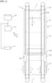
Fig. 2 is a longitudinal sectional view illustrating a relationship between a conveyance claw and an abutment body according to the present embodiment. -
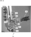
Fig. 3 is a photograph indicating the abutment body and a brush according to the present embodiment. -
Fig. 4 is a front view illustrating the abutment body and the brush according to the present embodiment. -
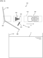
Fig. 5 is a side view illustrating an example of a solder removing mechanism according to the present embodiment. -
Fig. 6 is a side view illustrating another example of the solder removing mechanism according to the present embodiment. -
Fig. 7 is a side view illustrating an example of a jet soldering apparatus according to the present embodiment. -
Fig. 8 is a side view illustrating another example of the jet soldering apparatus according to the present embodiment. - A soldering apparatus illustrated in
Fig. 1 is an apparatus that performs soldering processing on asubstrate 200 on which electronic components such as semiconductor elements, resistors, and capacitors are mounted on a circuit. Typically, the electronic components and the like are positioned on a lower side of thesubstrate 200. The soldering apparatus has a main body 1 and aconveyance unit 5 that conveys thesubstrate 200. The main body 1 has a carry-inport 2 through which thesubstrate 200 is carried in and a carry-outport 3 through which thesubstrate 200 is carried out. Thesubstrate 200 may be conveyed at a predetermined angle, for example, an inclination of about 3 to 6 degrees when viewed from the side (seeFigs. 7 and8 ). In this case, a downstream side is positioned at a higher position than an upstream side in a substrate conveyance direction A. However, the present invention is not limited thereto, and thesubstrate 200 may be horizontally conveyed, for example. Aconveyance unit 5 may have a conveyance rail 6 (seeFig. 7 ), conveyance claws 510 (seeFig. 2 ) movable along theconveyance rail 6 in a state of gripping asubstrate 200, and a conveyance drive unit (not illustrated) that applies driving force for moving theconveyance claws 510 along theconveyance rail 6. As theconveyance rail 6, aluminum, iron, stainless steel, or the like, may be used. Theconveyance claw 510 has arecess 511 for gripping the substrate 200 (seeFig. 2 ). - As illustrated in
Fig. 1 , the main body 1 may be provided with afluxer 10 for applying flux to thesubstrate 200, apreheater unit 15 for preheating thesubstrate 200 coated with flux, ajet soldering apparatus 100 for jetting molten solder into contact with thesubstrate 200, and acooler 20 for cooling the solderedsubstrate 200. Thesubstrate 200 conveyed along theconveyance rail 6 of theconveyance unit 5 sequentially passes through thefluxer 10, thepreheater unit 15, thejet soldering apparatus 100, and thecooler 20. Note that inFig. 1 , the soldering apparatus is illustrated in an upper plan view except for thecontrol unit 50, thestorage unit 60, and anoperation unit 70 described later. - The
fluxer 10 is used to apply flux to the conveyedsubstrate 200. The flux may include a solvent, an activator, and the like. Thefluxer 10 may be provided with a plurality of coating apparatuses. The type of flux may be selectively used according to the type of solder and the type of thesubstrate 200. - The
preheater unit 15 heats thesubstrate 200 to uniformly raise thesubstrate 200 to a predetermined temperature. When thesubstrate 200 is heated in this manner, the solder is easily attached to a predetermined part of thesubstrate 200. For example, a halogen heater is used as thepreheater unit 15. The halogen heater can rapidly heat thesubstrate 200 to a set temperature. Furthermore. Thesubstrate 200 may be heated by blowing gas (hot air) heated by the heater onto thesubstrate 200 by a fan. Furthermore, as thepreheater unit 15, a farinfrared panel heater or the like may be used. - The cooler 20 has a cooling fan which is not illustrated, and cools the
substrate 200 soldered by thejet soldering apparatus 100. The control of the cooling fan may be only ON and OFF, but the wind speed may be adjusted. Furthermore, as thecooler 20, a chiller or the like may be used to cool thesubstrate 200 to a predetermined temperature. - The
control unit 50 illustrated inFig. 1 is communicably connected to theconveyance unit 5, thefluxer 10, thepreheater unit 15, thejet soldering apparatus 100, the cooler 20, theoperation unit 70, and thestorage unit 60. The communicable connections include both wired and wireless connections. Theoperation unit 70 may have a liquid crystal display panel, a numeric keypad, or the like, and is typically a personal computer, a smartphone, a tablet, a touch panel or the like. When an operator operates theoperation unit 70, thecontrol unit 50 may control a conveyance speed by theconveyance unit 5, a timing of conveying thesubstrate 200, a temperature of the flux at thefluxer 10, an application amount of the flux, a temperature of thepreheater unit 15, a temperature of molten solder S of thejet soldering apparatus 100, a jet amount, a jet speed, ON and OFF of the cooling fan of the cooler 20, and the like. Thestorage unit 60 may store information input by theoperation unit 70, an instruction of thecontrol unit 50, an operating time of thejet soldering apparatus 100, and the like. The conveyance speed of thesubstrate 200 is about 1 to 3 cm per second for example. - Next, an example of a method of treating the
substrate 200 will be described. - In a state where the
substrate 200 is sandwiched between a plurality of conveyance claws 510 (seeFig. 2 ), theconveyance claws 510 are moved along theconveyance rail 6, whereby thesubstrate 200 is conveyed. Thesubstrate 200 is carried into a main body 1 from a carry-inport 2. When thesubstrate 200 reaches afluxer 10, thefluxer 10 applies flux to a predetermined portion of thesubstrate 200. - The
conveyance claws 510 convey thesubstrate 200 to which the flux has been applied by thefluxer 10 to apreheater unit 15. Thepreheater unit 15 heats thesubstrate 200 to a predetermined temperature. - Next, the
conveyance claws 510 convey thesubstrate 200 heated to the predetermined temperature by thepreheater unit 15 to ajet soldering apparatus 100. Thejet soldering apparatus 100 solders a predetermined portion of thesubstrate 200. While thejet soldering apparatus 100 is supplying molten solder S, the molten solder S supplied from afirst supply port 125 and the molten solder S supplied from asecond supply port 135 are mixed, and the molten solder S is supplied to above theconveyance rail 6. The molten solder S is configured not to be separated from thesubstrate 200 conveyed by theconveyance claws 510 between thefirst supply port 125 and thesecond supply port 135. In a state where thesubstrate 200 does not exist, the molten solder S supplied from thefirst supply port 125 pushes up the molten solder S supplied from thesecond supply port 135, and a plurality of convex shapes corresponding tofirst openings 126 are formed by the molten solder S. - Next, the
conveyance claws 510 convey the solderedsubstrate 200 to a cooler 20. For example, a cooling fan of the cooler 20 cools the solderedsubstrate 200 for a predetermined period. After thesubstrate 200 is cooled, when theconveyance claws 510 discharge thesubstrate 200 from a carry-outport 3, soldering treatment to thesubstrate 200 is completed. - Thereafter, the
conveyance claws 510 are turned back to the outside of a peripheral edge along theconveyance rail 6 and return toward the carry-inport 2. Thus, a conveyance direction A of the substrate faces an opposite direction of a conveyance direction B of the conveyance claws 510 (seeFig. 1 ). While theconveyance claws 510 are moving toward the carry-inport 2, theconveyance claws 510 pass through asolder removing mechanism 520. When theconveyance claws 510 pass through thesolder removing mechanism 520 in this manner, the solder adhering to theconveyance claws 510 is removed by thesolder removing mechanism 520. A pair ofsolder removing mechanisms 520 is provided so that the solder attached to each of theconveyance claws 510 gripping thesubstrate 200 can be removed. - When the
conveyance claws 510 that have passed through thesolder removing mechanism 520 return to the carry-inport 2, theconveyance claws 510 convey anothersubstrate 200. - Typically, a large number of the plurality of
conveyance claws 510 are arranged along theconveyance rail 6, and thesubstrate 200 is sequentially conveyed by the plurality ofconveyance claws 510 which are parts of a large number of conveyance rails 6. - Next, the
jet soldering apparatus 100 will be briefly described. - As illustrated in
Figs. 7 and8 , thejet soldering apparatus 100 may have astorage tank 110 for storing the molten solder S, and a supply port for supplying the molten solder S to thesubstrate 200. The supply port may have two types of thefirst supply port 125 and thesecond supply port 135. Then, the molten solder S may be jetted from thefirst supply port 125 by receiving driving force from afirst pump 141 that is a first drive unit, and the molten solder S may be jetted from thesecond supply port 135 by receiving driving force from asecond pump 146 that is a second drive unit. - The molten solder S jetted from the
first supply port 125 and thesecond supply port 135 is jetted upward from below. The molten solder S having received the driving force from thefirst pump 141 is pressure-fed in a duct and jetted toward thesubstrate 200 to attach the solder to a predetermined portion of thesubstrate 200. Similarly, the molten solder S having received the driving force from thesecond pump 146 is pressure-fed in a duct and jetted toward thesubstrate 200 to attach the solder to a predetermined portion of thesubstrate 200. - The
first supply port 125 of thejet soldering apparatus 100 has a plurality offirst openings 126, and thefirst openings 126 constitute a primary jet nozzle. The plurality offirst openings 126 are used to vigorously supply a large amount of molten solder S to thesubstrate 200. Asecond opening 136 of thesecond supply port 135 is a secondary jet nozzle, and is used to supply the molten solder S to thesubstrate 200 with weaker force than thefirst supply port 125. The jet solder supplied from thefirst supply port 125 is a dynamic supply for vigorously colliding the molten solder S against thesubstrate 200, and is a supply for spreading the molten solder S to every corner of thesubstrate 200. On the other hand, the jet solder supplied from thesecond supply port 135 is a static supply, and is a supply for cleanly attaching the solder to an electrode or the like of thesubstrate 200 by passing the jet solder through the molten solder S having a gentle flow. The configuration of the jet soldering apparatus and conditions such as a force of the jet of the molten solder are examples, and the present application is not limited to the above configuration. - A
first supply unit 120 has afirst housing 121 and thefirst supply port 125 provided on an upper surface of thefirst housing 121 and having one or the plurality offirst openings 126 for supplying the molten solder S. Thefirst opening 126 may be provided so as to protrude upward from the upper surface of thefirst housing 121. Asecond supply unit 130 has asecond housing 131 and thesecond supply port 135 provided on an upper surface of thesecond housing 131 and having one or a plurality of thesecond openings 136 for supplying the molten solder S. Thefirst housing 121 and thesecond housing 131 may be provided apart from each other (seeFig. 7 ), but they may be provided integrally (seeFig. 8 ). In a case where thefirst housing 121 and thesecond housing 131 are integrated, a part of the wall surface may be shared. - An aspect may be adopted in which no opening or gap through which the molten solder S falls downward is provided between the
first supply port 125 and thesecond supply port 135 on an upper surface of thefirst housing 121 and thesecond housing 131 along the substrate conveyance direction A. When an opening or a gap through which the molten solder S falls downward is provided, a surface area where the molten solder S comes into contact with oxygen increases, and an oxide is generated. On the other hand, in a case of adopting an aspect in which a part where the molten solder S falls, such as an opening or a gap, is not provided between thefirst supply port 125 and thesecond supply port 135 along the substrate conveyance direction A as in the present aspect, the molten solder S does not fall between thefirst supply port 125 and thesecond supply port 135 along the substrate conveyance direction A, so that generation of an oxide of the molten solder S can be prevented. - Next, the
solder removing mechanism 520 will be described. - As illustrated in
Fig. 2 , thesolder removing mechanism 520 of the present embodiment has anabutment body 530 that can relatively pass throughrecesses 511 of the movingconveyance claws 510 or below the movingconveyance claws 510 after thesubstrate 200 is removed from theconveyance claws 510 and conveyed. InFig. 2 , theconveyance claws 510 gripping thesubstrate 200 move toward a front surface side of a paper surface, but theconveyance claws 510 not gripping thesubstrate 200 illustrated on the left and right sides ofFig. 2 move toward a back surface side of the paper surface. In the present application, "can pass" means can relatively pass. Typically, in a state where theconveyance claws 510 move and theabutment body 530 is stopped, theconveyance claws 510 pass through theabutment body 530, so that theabutment body 530 relatively passes through therecesses 511 of the movingconveyance claws 510 or below the movingconveyance claws 510. - The
abutment body 530 abuts on the cured solder attached to theconveyance claws 510 to remove the solder. By adopting such anabutment body 530, the solder attached to theconveyance claws 510 and cured can be more reliably scraped off. When only a brush is used as in the related art, the solder firmly attached to theconveyance claws 510 may not be scraped off. In this regard, by adopting theabutment body 530 as in the present embodiment, it is possible to prevent occurrence of such a situation. In particular, in the case of specific solder such as Sn-58Bi (Bi: 58 mass%, remaining part: Sn), the solder tends to firmly adhere to theconveyance claws 510, and thus it is advantageous to provide theabutment body 530 as in the present embodiment. More specifically, adhesive force of Sn-Bi solder such as Sn-58Bi is much stronger than an SAC (Sn-Ag-Cu) composition, and abrush 590 in the related art may not remove the adhered solder. In this regard, by adopting the aspect of the present embodiment, the Sn-Bi solder having strong adhesion force can be more reliably scraped off. In addition, an amount of the Sn-Bi solder attached to theconveyance claws 510 is larger than that of the SAC composition, and thus, an amount of solder to be scraped off is larger. For this reason, in a case where thebrush 590 in the related art is adopted, clogging, or the like, is also concerned. On the other hand, according to the aspect of the present embodiment, there is no element in which the solder scraped off is entangled in the removal mechanism as in the case of adopting thebrush 590, and thus, such a concern can also be reduced. The solder having strong adhesion force is not limited to the Sn-Bi solder, and the present embodiment can exhibit the effect even in another solder composition having strong adhesion force such as the Sn-Sb solder. - A pair of the
conveyance claws 510 sandwiching thesubstrate 200 is provided, and thus, a pair ofabutment bodies 530 may also be provided. As illustrated inFigs. 5 and6 , at least part of thesolder removing mechanism 520 may be located above thestorage tank 110 of the jet solder apparatus. By providing thesolder removing mechanism 520 above thestorage tank 110 of the jet solder apparatus, the solder scraped off from theconveyance claws 510 can be directly dropped into thestorage tank 110 and reused for soldering, and accumulation of the scraped solder in thejet soldering apparatus 100 can be prevented. Theconveyance claw 510 may be made of resin or metal, and when made of metal, may be made of stainless steel such as SUS. - As illustrated in
Figs. 2 ,5 , and6 , theabutment body 530 may have afirst abutment body 540 that can relatively pass through therecesses 511 of the movingconveyance claws 510 and can abut on the cured solder attached to therecesses 511 of theconveyance claws 510, and asecond abutment body 550 that can relatively pass under the movingconveyance claws 510 and can abut on the cured solder attached to a lower side of theconveyance claws 510. Thefirst abutment body 540 may have a shape slightly smaller than therecess 511 and matching a shape of therecess 511. Thefirst abutment body 540 may have a shape similar to the shape of therecess 511. As described above, thefirst abutment body 540 is smaller than therecess 511 and has a shape matching the shape of therecess 511, so that the solder attached to therecess 511 can be more reliably removed. - As illustrated in
Figs. 3 and4 , thefirst abutment body 540 may be an abutment plate. Thefirst abutment body 540 may have a firstproximal end part 545, a firstdistal end part 543, and a firstbent part 541 provided between the firstproximal end part 545 and the firstdistal end part 543. The firstdistal end part 543 may extend toward a downstream side (the right side inFig. 3 ) in the moving direction B of theconveyance claw 510 with reference to the firstbent part 541. When thefirst abutment body 540 is linear without the first bent part 541 (although thefirst abutment body 540 is basically configured not to abut on the conveyance claws 510), there is a possibility that thefirst abutment body 540 is caught by theconveyance claws 510 for some reason and the movement of theconveyance claws 510 is stopped. On the other hand, with the configuration in which the firstdistal end part 543 extends toward the downstream side in the moving direction B of theconveyance claw 510 as in the present aspect, even if the firstdistal end part 543 of thefirst abutment body 540 abuts on theconveyance claws 510 for some reason, it is possible to reduce a possibility that thefirst abutment body 540 is caught by theconveyance claw 510 and the movement of theconveyance claws 510 is stopped. If the movement of theconveyance claws 510 is stopped, the treatment itself on thesubstrate 200 is stopped, but by adopting this aspect, it is possible to prevent such a circumstance. Note that the firstdistal end part 543 extends toward the inside of the soldering apparatus, and inFig. 2 , the firstdistal end part 543 of thefirst abutment body 540 on the right side extends toward the left side, and the firstdistal end part 543 of thefirst abutment body 540 on the left side extends toward the right side. - Similarly to the
first abutment body 540, thesecond abutment body 550 may also be formed of an abutment plate. As illustrated inFigs. 3 and4 , thesecond abutment body 550 may have a secondproximal end part 555, a seconddistal end part 553, and a secondbent part 551 provided between the secondproximal end part 555 and the seconddistal end part 553. The seconddistal end part 553 may extend toward the downstream side (the right side inFig. 3 ) in the moving direction B of theconveyance claw 510 with reference to the secondbent part 551. For the same reason as described for thefirst abutment body 540, the seconddistal end part 553 is configured to extend toward the downstream side in the moving direction B of theconveyance claw 510 as described above, whereby thesecond abutment body 550 can be prevented from being caught by theconveyance claws 510. In other words, although thesecond abutment body 550 is basically configured not to abut on theconveyance claws 510, even if thesecond abutment body 550 abuts on theconveyance claws 510 for some reason, thesecond abutment body 550 can be prevented from hindering the movement of theconveyance claws 510. Note that in a similar manner to the firstdistal end part 543, the seconddistal end part 553 also extends toward the inside of the soldering apparatus. - The
abutment body 530 may be made of metal, or may be made of stainless steel such as SUS or iron. However, stainless steel is preferable from the viewpoint that rust is hardly generated. Only a pair of thefirst abutment body 540 and thesecond abutment body 550 may be provided in the soldering apparatus, or a plurality of pairs thereof may be provided. - As illustrated in
Figs. 5 and6 , aguide part 580 may be provided below theabutment body 530 to guide the solid solder falling from theconveyance claws 510 to thestorage tank 110 of the jet solder apparatus. By providing such aguide part 580, it is possible to more reliably guide the solder which abuts on theabutment body 530 and is scraped off to thestorage tank 110, and it is possible to melt and reuse the solder. Further, it is also possible to more reliably prevent the solder scraped off from accumulating in thejet soldering apparatus 100. In particular, an amount of adhesion to theconveyance claws 510 is large in specific solder such as Sn-Bi solder, and thus, adopting such an aspect is very useful from both the viewpoint of reuse and the viewpoint of preventing accumulation of the scraped solder in thejet soldering apparatus 100. - A
cover 585 that is positioned on the downstream side (the left side inFigs. 5 and6 ) in the moving direction B of theconveyance claws 510 and extends in the vertical direction may be provided. According to the study of the inventors of the present application, the solder scraped off from theconveyance claws 510 tends to splash to the upstream side in the moving direction B (the left side inFigs. 5 and6 ). However, by providing such acover 585, it is possible to prevent the solder scraped off by coming into contact with theabutment body 530 from splashing to the upstream side in the moving direction B of the conveyance claws 510 (the left side inFigs. 5 and6 ). In the present embodiment, an aspect is adopted in which thecover 585 and theguide part 580 are integrated, and these are connected via a connectingpart 589, but the present invention is not limited to such an aspect, and thecover 585 and theguide part 580 may be separated. However, in a case where thecover 585 and theguide part 580 are integrated as in the present aspect, it is advantageous in that the solid solder colliding with thecover 585 can be directly guided to thestorage tank 110 by theguide part 580. - A
brush 590 positioned on the downstream side (the right side inFigs. 5 and6 ) of the conveyance direction B of theconveyance claws 510 with respect to theabutment body 530 may be provided. By providing such abrush 590, the solder adhering to theconveyance claws 510 can be more reliably removed. In other words, even if the solder attached to theconveyance claws 510 can be scraped by theabutment body 530 made of a metal plate, or the like, the scraped solder may be placed on theconveyance claws 510. In this regard, by providing thebrush 590 as in the present aspect, the solder placed on theconveyance claws 510 can be dropped. Here, in a case where thebrush 590 is made of metal, it is advantageous in that the effect is also enhanced. However, the material of thebrush 590 is not particularly limited, and thebrush 590 may be, for example, made of horse bristles. In a case where thebrush 590 is made of metal, stainless steel such as SUS or iron may be used. However, stainless steel is preferable from the viewpoint that rust is hardly generated. As illustrated inFig. 3 , theabutment body 530 and thebrush 590 may be integrally configured. - The
abutment body 530 may have athird abutment body 560 that abuts on the solder attached above the conveyance claws 510 (seeFig. 6 ). Although the solder usually does not adhere to an upper side of theconveyance claws 510, thethird abutment body 560 may be provided because the solder may adhere for some reason. Similarly to thefirst abutment body 540 and thesecond abutment body 550, thethird abutment body 560 may also be configured such that a distal end side of thethird abutment body 560 extends toward the downstream side (the right side inFig. 6 ) in the conveyance direction B of theconveyance claws 510. - The description of each embodiment and the disclosure of the drawings described above are merely examples for describing the invention described in the claims, and the invention described in the claims is not limited by the description of each embodiment or the disclosure of the drawings described above. In addition, the description of the claims as originally filed is merely an example, and the description of the claims can be appropriately changed based on the description of the specification, the drawings, and the like.
-
- 110
- storage tank
- 200
- substrate
- 510
- conveyance claw
- 511
- recess
- 520
- solder removing mechanism
- 530
- abutment body
- 540
- first abutment body
- 541
- first bent part
- 543
- first distal end part
- 550
- second abutment body
- 551
- second bent part
- 553
- second distal end part
- 580
- guide part
- 585
- cover
- 590
- brush
Claims (7)
- A solder removing mechanism for removing solder from conveyance claws for conveying a substrate to which the solder is supplied, the solder removing comprising an abutment body that can relatively pass through recesses of the conveyance claws or below the conveyance claws.
- The solder removing mechanism according to claim 1,
wherein the abutment body has a first abutment body that can relatively pass through the recesses of the conveyance claws, and a second abutment body that can relatively pass under the conveyance claws. - The solder removing mechanism according to claim 1 or 2 comprising a brush positioned on a downstream side of the abutment body in a conveyance direction of the conveyance claws.
- The solder removing mechanism according to claim 1 or 2,
wherein the abutment body is an abutment plate. - The solder removing mechanism according to claim 1 or 2,
wherein the abutment body has a bent part, and a distal end part that extends from the bent part toward a downstream side in a moving direction of the conveyance claws. - The solder removing mechanism according to claim 1 or 2 comprising a guide part that elongates below the abutment body and that guides the solder falling from the conveyance claws to a storage tank.
- The solder removing mechanism according to claim 1 or 2 comprising a cover that is provided on an upstream side of the abutment body in a moving direction of the conveyance claws and that extends in a vertical direction.
Applications Claiming Priority (2)
| Application Number | Priority Date | Filing Date | Title |
|---|---|---|---|
| JP2022094829 | 2022-06-13 | ||
| PCT/JP2023/021650 WO2023243576A1 (en) | 2022-06-13 | 2023-06-12 | Jet soldering device |
Publications (2)
| Publication Number | Publication Date |
|---|---|
| EP4535936A1 true EP4535936A1 (en) | 2025-04-09 |
| EP4535936A4 EP4535936A4 (en) | 2025-10-29 |
Family
ID=89191216
Family Applications (1)
| Application Number | Title | Priority Date | Filing Date |
|---|---|---|---|
| EP23823866.1A Pending EP4535936A4 (en) | 2022-06-13 | 2023-06-12 | BLASTING SOLDERING DEVICE |
Country Status (9)
| Country | Link |
|---|---|
| US (1) | US12434316B2 (en) |
| EP (1) | EP4535936A4 (en) |
| JP (1) | JP7506353B2 (en) |
| KR (1) | KR102867511B1 (en) |
| CN (1) | CN119404601A (en) |
| MX (1) | MX2024015340A (en) |
| MY (1) | MY209351A (en) |
| TW (1) | TWI887678B (en) |
| WO (1) | WO2023243576A1 (en) |
Family Cites Families (10)
| Publication number | Priority date | Publication date | Assignee | Title |
|---|---|---|---|---|
| US2857608A (en) * | 1955-10-28 | 1958-10-28 | Raymond H Schwartz | Golf club cleaning device having a blade-carrying shank and brushretaining means in combination |
| US6273317B1 (en) * | 1998-10-29 | 2001-08-14 | Denso Corporation | Flow soldering apparatus having resilient substrate clamping mechanism and solder oxide film removing mechanism |
| JP4038904B2 (en) | 1998-11-17 | 2008-01-30 | 株式会社デンソー | Jet soldering equipment |
| JP3593923B2 (en) * | 1999-06-23 | 2004-11-24 | 住友電装株式会社 | Desoldering equipment for board carrier |
| JP2002190666A (en) | 2000-12-20 | 2002-07-05 | Stanley Electric Co Ltd | Automatic soldering equipment |
| US6666370B2 (en) * | 2002-01-18 | 2003-12-23 | Speedline Technologies, Inc. | Solder-dross mixture separation method and apparatus |
| JP2005236066A (en) | 2004-02-20 | 2005-09-02 | Nihon Dennetsu Keiki Co Ltd | Soldering device |
| JP2011235259A (en) | 2010-05-13 | 2011-11-24 | Sawa Corporation | Device for removing adhered substance |
| CN208825948U (en) * | 2018-09-26 | 2019-05-07 | 新乡美达高频电子有限公司 | A kind of scruff cleaning plant for wave peak welder transportation link claw |
| DE112021004789T5 (en) | 2020-11-09 | 2023-08-31 | Fanuc Corporation | INDUSTRIAL MACHINE WITH PAIR OF POSITIONERS TO HOLD A WORKPIECE |
-
2023
- 2023-06-12 WO PCT/JP2023/021650 patent/WO2023243576A1/en not_active Ceased
- 2023-06-12 KR KR1020257000634A patent/KR102867511B1/en active Active
- 2023-06-12 JP JP2024508456A patent/JP7506353B2/en active Active
- 2023-06-12 EP EP23823866.1A patent/EP4535936A4/en active Pending
- 2023-06-12 MY MYPI2024007063A patent/MY209351A/en unknown
- 2023-06-12 CN CN202380043205.5A patent/CN119404601A/en active Pending
- 2023-06-12 US US18/874,560 patent/US12434316B2/en active Active
- 2023-06-13 TW TW112122033A patent/TWI887678B/en active
-
2024
- 2024-12-10 MX MX2024015340A patent/MX2024015340A/en unknown
Also Published As
| Publication number | Publication date |
|---|---|
| TW202406654A (en) | 2024-02-16 |
| EP4535936A4 (en) | 2025-10-29 |
| CN119404601A (en) | 2025-02-07 |
| MX2024015340A (en) | 2025-02-10 |
| WO2023243576A1 (en) | 2023-12-21 |
| KR20250012191A (en) | 2025-01-23 |
| US20250162053A1 (en) | 2025-05-22 |
| JPWO2023243576A1 (en) | 2023-12-21 |
| MY209351A (en) | 2025-07-03 |
| TWI887678B (en) | 2025-06-21 |
| KR102867511B1 (en) | 2025-10-14 |
| JP7506353B2 (en) | 2024-06-26 |
| US12434316B2 (en) | 2025-10-07 |
Similar Documents
| Publication | Publication Date | Title |
|---|---|---|
| EP3183086B1 (en) | Wave soldering nozzle system and method of wave soldering | |
| US20070039999A1 (en) | Soldering apparatus and soldering method | |
| EP4286087B1 (en) | Jet soldering device | |
| JP5533650B2 (en) | Automatic soldering equipment | |
| US12434316B2 (en) | Soldering apparatus | |
| JP4012515B2 (en) | Soldering method and soldering apparatus | |
| US20250339912A1 (en) | Solder processing apparatus | |
| JP2025097093A (en) | Conveyor claw and soldering device | |
| JP4186635B2 (en) | Solder cooling method, solder cooling device, and solder reflow device | |
| HK40117550A (en) | Jet soldering device | |
| KR100776262B1 (en) | Automatic Soldering Equipment | |
| JP7667487B1 (en) | Wave soldering equipment | |
| JP7530031B2 (en) | Wave soldering equipment | |
| WO2025142371A1 (en) | Jet solder device | |
| JP2005167001A (en) | Device and method for soldering substrate | |
| JP2005236066A (en) | Soldering device | |
| JP2003179337A (en) | Cooling device for soldering and soldering device |
Legal Events
| Date | Code | Title | Description |
|---|---|---|---|
| STAA | Information on the status of an ep patent application or granted ep patent |
Free format text: STATUS: THE INTERNATIONAL PUBLICATION HAS BEEN MADE |
|
| PUAI | Public reference made under article 153(3) epc to a published international application that has entered the european phase |
Free format text: ORIGINAL CODE: 0009012 |
|
| STAA | Information on the status of an ep patent application or granted ep patent |
Free format text: STATUS: REQUEST FOR EXAMINATION WAS MADE |
|
| 17P | Request for examination filed |
Effective date: 20241231 |
|
| AK | Designated contracting states |
Kind code of ref document: A1 Designated state(s): AL AT BE BG CH CY CZ DE DK EE ES FI FR GB GR HR HU IE IS IT LI LT LU LV MC ME MK MT NL NO PL PT RO RS SE SI SK SM TR |
|
| DAV | Request for validation of the european patent (deleted) | ||
| DAX | Request for extension of the european patent (deleted) | ||
| A4 | Supplementary search report drawn up and despatched |
Effective date: 20250929 |
|
| RIC1 | Information provided on ipc code assigned before grant |
Ipc: H05K 3/34 20060101AFI20250923BHEP Ipc: B23K 1/00 20060101ALI20250923BHEP Ipc: B23K 3/00 20060101ALI20250923BHEP Ipc: B23K 3/08 20060101ALI20250923BHEP Ipc: B23K 1/018 20060101ALI20250923BHEP Ipc: B23K 1/08 20060101ALI20250923BHEP Ipc: B23K 3/06 20060101ALI20250923BHEP |