EP4535888A1 - Verfahren und vorrichtung zur strahlbestimmung - Google Patents
Verfahren und vorrichtung zur strahlbestimmung Download PDFInfo
- Publication number
- EP4535888A1 EP4535888A1 EP22943082.2A EP22943082A EP4535888A1 EP 4535888 A1 EP4535888 A1 EP 4535888A1 EP 22943082 A EP22943082 A EP 22943082A EP 4535888 A1 EP4535888 A1 EP 4535888A1
- Authority
- EP
- European Patent Office
- Prior art keywords
- transmission
- downlink channel
- terminal device
- sdt
- channel transmission
- Prior art date
- Legal status (The legal status is an assumption and is not a legal conclusion. Google has not performed a legal analysis and makes no representation as to the accuracy of the status listed.)
- Pending
Links
Images


Classifications
-
- H—ELECTRICITY
- H04—ELECTRIC COMMUNICATION TECHNIQUE
- H04W—WIRELESS COMMUNICATION NETWORKS
- H04W72/00—Local resource management
- H04W72/04—Wireless resource allocation
- H04W72/044—Wireless resource allocation based on the type of the allocated resource
- H04W72/046—Wireless resource allocation based on the type of the allocated resource the resource being in the space domain, e.g. beams
-
- H—ELECTRICITY
- H04—ELECTRIC COMMUNICATION TECHNIQUE
- H04W—WIRELESS COMMUNICATION NETWORKS
- H04W72/00—Local resource management
- H04W72/20—Control channels or signalling for resource management
- H04W72/23—Control channels or signalling for resource management in the downlink direction of a wireless link, i.e. towards a terminal
-
- H—ELECTRICITY
- H04—ELECTRIC COMMUNICATION TECHNIQUE
- H04B—TRANSMISSION
- H04B7/00—Radio transmission systems, i.e. using radiation field
- H04B7/02—Diversity systems; Multi-antenna system, i.e. transmission or reception using multiple antennas
- H04B7/04—Diversity systems; Multi-antenna system, i.e. transmission or reception using multiple antennas using two or more spaced independent antennas
- H04B7/06—Diversity systems; Multi-antenna system, i.e. transmission or reception using multiple antennas using two or more spaced independent antennas at the transmitting station
- H04B7/0686—Hybrid systems, i.e. switching and simultaneous transmission
- H04B7/0695—Hybrid systems, i.e. switching and simultaneous transmission using beam selection
- H04B7/06952—Selecting one or more beams from a plurality of beams, e.g. beam training, management or sweeping
- H04B7/06968—Selecting one or more beams from a plurality of beams, e.g. beam training, management or sweeping using quasi-colocation [QCL] between signals
-
- H—ELECTRICITY
- H04—ELECTRIC COMMUNICATION TECHNIQUE
- H04B—TRANSMISSION
- H04B7/00—Radio transmission systems, i.e. using radiation field
- H04B7/02—Diversity systems; Multi-antenna system, i.e. transmission or reception using multiple antennas
- H04B7/04—Diversity systems; Multi-antenna system, i.e. transmission or reception using multiple antennas using two or more spaced independent antennas
- H04B7/08—Diversity systems; Multi-antenna system, i.e. transmission or reception using multiple antennas using two or more spaced independent antennas at the receiving station
- H04B7/0868—Hybrid systems, i.e. switching and combining
- H04B7/088—Hybrid systems, i.e. switching and combining using beam selection
-
- H—ELECTRICITY
- H04—ELECTRIC COMMUNICATION TECHNIQUE
- H04L—TRANSMISSION OF DIGITAL INFORMATION, e.g. TELEGRAPHIC COMMUNICATION
- H04L5/00—Arrangements affording multiple use of the transmission path
- H04L5/003—Arrangements for allocating sub-channels of the transmission path
- H04L5/0044—Allocation of payload; Allocation of data channels, e.g. PDSCH or PUSCH
-
- H—ELECTRICITY
- H04—ELECTRIC COMMUNICATION TECHNIQUE
- H04W—WIRELESS COMMUNICATION NETWORKS
- H04W72/00—Local resource management
- H04W72/04—Wireless resource allocation
- H04W72/115—Grant-free or autonomous transmission
-
- H—ELECTRICITY
- H04—ELECTRIC COMMUNICATION TECHNIQUE
- H04W—WIRELESS COMMUNICATION NETWORKS
- H04W74/00—Wireless channel access
- H04W74/08—Non-scheduled access, e.g. ALOHA
- H04W74/0833—Random access procedures, e.g. with 4-step access
-
- Y—GENERAL TAGGING OF NEW TECHNOLOGICAL DEVELOPMENTS; GENERAL TAGGING OF CROSS-SECTIONAL TECHNOLOGIES SPANNING OVER SEVERAL SECTIONS OF THE IPC; TECHNICAL SUBJECTS COVERED BY FORMER USPC CROSS-REFERENCE ART COLLECTIONS [XRACs] AND DIGESTS
- Y02—TECHNOLOGIES OR APPLICATIONS FOR MITIGATION OR ADAPTATION AGAINST CLIMATE CHANGE
- Y02D—CLIMATE CHANGE MITIGATION TECHNOLOGIES IN INFORMATION AND COMMUNICATION TECHNOLOGIES [ICT], I.E. INFORMATION AND COMMUNICATION TECHNOLOGIES AIMING AT THE REDUCTION OF THEIR OWN ENERGY USE
- Y02D30/00—Reducing energy consumption in communication networks
- Y02D30/70—Reducing energy consumption in communication networks in wireless communication networks
Definitions
- the disclosure relates to a field of communication technology, in particular to a beam determination method and a device.
- the communication device includes a processing module.
- the processing module is configured to, in a transmission process of SDT, determine latest uplink transmission relative to downlink channel transmission.
- the processing module is further configured to determine a beam used for the downlink channel transmission of the terminal device according to an SSB associated with the latest uplink transmission.
- a communication device includes: a processor and an interface circuit.
- the interface circuit is configured to receive code instructions and transmit the code instructions to the processor.
- the processor is configured to run the code instructions to perform the method described in the first aspect above.
- the RA process refers to a process from a time when a user sends a random access preamble to try to access the network to a time when a basic signaling connection is established with the network.
- the RA is a very critical step in a mobile communication system and is also the last step in establishing a communication link between a terminal device and the network.
- the terminal device can exchange information with a network side device through RA.
- the RA process may include 2-step random access and 4-step random access.
- the terminal If uplink data is to be transmitted in an inactive state, the terminal first confirms the TA validity, a synchronization signal reference signal received power (SS-RSRP) and a size of data. When all conditions such as the TA validity, the SS-RSRP and the size of data are met, small data transmission can be performed using semi-persistent resources configured by the network side device. Otherwise, for example, if the size of uplink data to be transmitted by the terminal exceeds a threshold, the terminal executes the 4-step RA process and enters into the connected state, to perform data transmission in the connected state.
- SS-RSRP synchronization signal reference signal received power
- Scrambling is a method for processing digital signals.
- a scrambling code is XORed with an original signal to obtain a new signal.
- physical channels of uplinks are scrambled to distinguish different terminal devices, and downlinks are scrambled to distinguish cells and channels.
- a scrambling code can be used to scramble and descramble the original signal.
- the scrambling code may be used to scramble downlink control information (DCI), or scramble a PDCCH.
- Scrambling the DCI may specifically refer to scrambling a cyclic redundancy check (CRC) field of the DCI.
- CRC cyclic redundancy check
- the scrambling code may include, but is not limited to, a cell radio network temporary identifier (C-RNTI), a temporary cell radio network temporary identifier (TC-RNTI), a random access radio network temporary identifier (RA-RNTI), a system information radio network temporary identifier (SI-RNTI) and a paging radio network temporary identifier (P-RNTI).
- C-RNTI cell radio network temporary identifier
- TC-RNTI temporary cell radio network temporary identifier
- RA-RNTI random access radio network temporary identifier
- SI-RNTI system information radio network temporary identifier
- P-RNTI paging radio network temporary identifier
- the terminal device If the terminal device is in a RRC-connected (radio resource control connected) state, it represents that the terminal device has been assigned with the C-RNTI, when initiating a RA request to the network side device, the terminal device needs to carry the C-RNTI in the request. If the terminal device is in a RRC idle state or an RRC inactive state, it represents that the terminal device has not been assigned with the C-RNTI, when the terminal device requests an RRC connection, the network side device may allocate a temporary C-RNTI to the terminal device in a subsequent response message, which is noted as TC-RNTI. If the RA process of the terminal device is successful, the TC-RNTI can be converted into the C-RNTI.
- RRC-connected radio resource control connected
- generation of the RA-RNTI is related to the time-frequency resources used by the terminal device to send the preamble. For example, when a terminal device A and a terminal device B both initiate the RA using the same RA channel time-frequency resource, the corresponding RA-RNTIs are the same.
- the terminal device 102 in the embodiments of the disclosure is an entity on a user side for receiving or transmitting signals, such as a cellular phone.
- the terminal device may also be referred to as a terminal, a user equipment (UE), a mobile station (MS), a mobile terminal (MT), and the like.
- the method is performed by a network side device.
- the method may include, but is not limited to, the following steps.
- the SDT may be SDT based on a RA process or SDT based on a semi-persistent configuration.
- the SDT based on the RA process is also called as RA-SDT (random access-SDT), and the SDT based on the semi-persistent configuration is also called as configured grant-SDT (CG-SDT).
- RA-SDT random access-SDT
- CG-SDT configured grant-SDT
- the network side device determines the latest uplink transmission in the transmission process of SDT, and determines a beam used for the downlink channel transmission of the terminal device according to an SSB associated with the latest uplink transmission.
- the beam is a transmitting beam used by the network side device for the downlink channel transmission.
- the network side device can use the determined beam to send a downlink channel.
- an RRCresumerelease message carries information such as semi-persistent time-frequency domain resource allocation information required for SDT and timing advance (TA) validity judgment.
- TA timing advance
- the terminal device first confirms the TA validity, a coverage condition and a size of data. If a threshold is met, the terminal device uses the semi-persistent resources configured by the network side device for SDT.
- determining the latest uplink transmission of the terminal device relative to the downlink channel transmission includes: in a transmission process of CG-SDT, determining that the latest uplink transmission of the terminal device relative to the downlink channel transmission is a PRACH transmission or a PUSCH transmission.
- the latest uplink transmission of the terminal device relative to the downlink channel transmission is determined.
- the latest uplink transmission of the terminal device relative to the downlink channel transmission is determined to be as the PUSCH transmission.
- the latest uplink transmission of the terminal device relative to the downlink channel transmission is determined.
- the latest uplink transmission of the terminal device relative to the downlink channel transmission is the PRACH transmission.
- a beam used for the downlink channel transmission of the terminal device is determined according to an SSB associated with the latest uplink transmission.
- the downlink channel transmission may also be a PDCCH transmission scrambled by a C-RNTI and/or a CS-RNTI, and/or a PDSCH transmission scheduled by DCI and scrambled by the C-RNTI.
- the terminal device initiates a RA request and requests an uplink resource to perform uplink data transmission. Then, the terminal device monitors the PDCCH scrambled by the C-RNTI, and receives a PDSCH or sends a PUSCH, while performing a corresponding RACH procedure.
- the network side device may use a beam for uplink transmission of the terminal device as a beam for downlink channel data transmission to perform downlink channel transmission.
- the uplink transmission of the terminal device may include: a beam used by the terminal device for the PRACH transmission, and a beam used by the terminal device for the PUSCH transmission. It is noted that the terminal device may also perform one or more PRACH transmissions or one or more PUSCH transmissions.
- the beam used for downlink channel transmission of the terminal device is determined according to the SSB associated with the PUSCH transmission, which can be the same beam used for the PUSCH transmission.
- determining the beam used for the downlink channel transmission of the terminal device according to the SSB associated with the latest uplink transmission may include determining the beam used for the downlink channel transmission of the terminal device according to the QCL relationship and the SSB associated with the CG-PUSCH transmission. Therefore, the beam used for the downlink channel transmission can be determined, such that a downlink channel can use a suitable beam for transmission, reliability of the downlink channel transmission may be improved.
- determining the beam used for the downlink channel transmission of the terminal device according to the SSB associated with the latest uplink transmission may include determining the beam used for the downlink channel transmission of the terminal device according to the SSB associated with the PRACH transmission and the QCL relationship. Therefore, the beam used for the downlink channel transmission can be determined, such that a downlink channel can use a suitable beam for transmission, reliability of the downlink channel transmission may be improved.
- Determining, according to the QCL relationship and the SSB associated with PRACH transmission, the beam used for the downlink channel transmission of the terminal device may determining, according to the QCL relationship and the SSB associated with PRACH transmission, that the beam used for the downlink channel transmission of the terminal device is the same as the beam used for PRACH transmission.
- the designated downlink channel transmission includes at least one of:
- Determining the beam used for the designated downlink channel transmission of the terminal device according to the SSB associated with the PRACH transmission and the QCL relationship may include determining that the beam used for the designated downlink channel transmission of the terminal device is the same as the beam used for the PRACH transmission according to the SSB associated with the PRACH transmission and the QCL relationship.
- the method is performed by a network side device and/or a terminal device.
- the method may include, but is not limited to, the following steps.
- the transmission process of CG-SDT it is determined that the latest uplink transmission of the terminal device relative to the downlink channel transmission is the PRACH transmission.
- the latest uplink transmission is determined by comparing a sequence of the PUSCH transmission and the PRACH transmission.
- the latest uplink transmission is determined to be as the PUSCH transmission, or the latest uplink transmission is determined to be as the PRACH transmission.
- the network side device determines a transmitting beam used for the downlink channel transmission of the terminal device according to the SSB associated with the PRACH transmission, and/or the terminal device determines a receiving beam used for the downlink channel transmission of the terminal device according to the SSB associated with the PRACH transmission. Therefore, the beam used for the downlink channel transmission can be determined, such that a downlink channel can use a suitable beam for transmission, reliability of the downlink channel transmission may be improved.
- the method is performed by a network side device and/or a terminal device.
- the method may include, but is not limited to, the following steps.
- the SSB associated with the PRACH transmission has a QCL relationship with a designated downlink channel transmission in the downlink channel transmission. According to the SSB associated with the PRACH transmission and the QCL relationship, the beam used for the downlink channel transmission of the terminal device is determined.
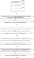
- FIG. 7 is a flowchart of a beam determination method provided by an embodiment of the disclosure.
- the method is performed by a network side device and/or a terminal device.
- the method may include, but is not limited to, the following steps.
- the transmission process of CG-SDT it is determined that the latest uplink transmission of the terminal device relative to the downlink channel transmission is a PUSCH transmission.
- an SSB associated with the PRACH transmission has a QCL relationship with a designated downlink channel transmission in the downlink channel transmission, according to the SSB associated with the PRACH transmission and the QCL relationship, a beam used for the designated downlink channel transmission of the terminal device is determined.
- the network side device determines a transmitting beam used for the downlink channel transmission of the terminal device according to the SSB associated with the PUSCH transmission and the QCL relationship, and/or the terminal device determines a receiving beam used for the downlink channel transmission of the terminal device according to the SSB associated with the PUSCH transmission and the QCL relationship. Therefore, the beam used for the downlink channel transmission can be determined, such that a downlink channel can use a suitable beam for transmission, reliability of the downlink channel transmission may be improved.
- the network side device determines that the latest uplink transmission of the terminal device relative to the downlink channel transmission is the PUSCH transmission.
- the SSB associated with the PUSCH transmission has the QCL relationship with the downlink channel transmission. According to the SSB associated with the PUSCH transmission and the QCL relationship, the beam used for the downlink channel transmission of the terminal device is determined. Therefore, the beam used for the downlink channel transmission can be determined, such that a downlink channel can use a suitable beam for transmission, reliability of the downlink channel transmission may be improved.
- the method is performed by a network side device and/or a terminal device.
- the method may include, but is not limited to, the following steps.
- step S101 in a transmission process of RA-SDT, it is determined that the latest uplink transmission of the terminal device relative to the downlink channel transmission is a PRACH transmission.
- steps S101 and S102 of the embodiments of the disclosure can be reference with the relevant descriptions in the above embodiments, which will not be repeated here.
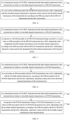
- FIG. 11 is a flowchart of a beam determination method provided by an embodiment of the disclosure.
- the designated downlink channel transmission includes at least one of:
- steps S111 and S112 of the embodiments of the disclosure can be reference with the relevant descriptions in the above embodiments, which will not be repeated here.
- FIG. 12 is a flowchart of a beam determination method provided by an embodiment of the disclosure.
- the method is performed by a terminal device.
- the method may include, but is not limited to, the following steps.
- the network side device determines the latest uplink transmission of the terminal device relative to the downlink channel transmission.
- the terminal device may perform one or more uplink transmissions, and determine the latest uplink transmission of the terminal device relative to the downlink channel transmission. In a case that the terminal device performs one uplink transmission, this transmission can be determined as the first uplink transmission of the terminal device. In a case that the terminal device performs multiple uplink transmissions, the latest uplink transmission of the terminal device relative to the downlink channel transmission may be determined.
- determining the latest uplink transmission of the terminal device relative to the downlink channel transmission includes: in a transmission process of CG-SDT, determining that the latest uplink transmission of the terminal device relative to the downlink channel transmission is a PRACH transmission or a PUSCH transmission.
- the latest uplink transmission is determined by comparing a sequence of the PUSCH transmission and the PRACH transmission. If the PRACH transmission is before the PUSCH transmission, the latest uplink transmission relative to the downlink channel transmission is determined to be as the PUSCH transmission. If the PUSCH transmission is before the PRACH transmission, the latest uplink transmission relative to the downlink channel transmission is determined to be as the PRACH transmission.
- determining the latest uplink transmission of the terminal device relative to the downlink channel transmission includes: in a transmission process of RA-SDT, determining that the latest uplink transmission of the terminal device relative to the downlink channel transmission is a PRACH transmission.
- the latest uplink transmission of the terminal device relative to downlink channel transmission is determined.
- the latest uplink transmission of the terminal device relative to downlink channel transmission is a PRACH transmission.
- each terminal device is assigned with one C-RNTI when it is in the inactive state.
- this C-RNTI may be the same as a C-RNTI in an RRC_CONNECTED state.
- this C-RNTI may be a TC-RNTI after contention resolution in the RACH procedure.
- the terminal device determines, in the transmission process of SDT, the latest uplink transmission to determine the beam used for the downlink channel transmission of the terminal device according to the SSB associated with the latest uplink transmission.
- the terminal device may start an SDT timer, e.g., T319a, after sending small data. Before the timer expires, scheduling and transmission of uplink data or downlink data between the terminal device and the network side device may be carried out. When the timer expires, the terminal device enters into an idle state.
- SDT timer e.g., T319a
- the network side device may use a beam for uplink transmission of the terminal device as a beam for downlink channel data transmission to perform downlink channel transmission.
- the uplink transmission of the terminal device may include: a beam used by the terminal device for PRACH transmission, and a beam used by the terminal device for PUSCH transmission. It is noted that the terminal device may also perform one or more PRACH transmissions or one or more PUSCH transmissions.
- the terminal device determines the latest uplink transmission.
- the beam used for uplink transmission can realize uplink transmitting.
- the network side device can send data for downlink channel transmission through the beam, and the terminal device can receive data for downlink channel transmission through the beam. Therefore, the beam used for the downlink channel transmission can be determined, such that a downlink channel can use a suitable beam for transmission, reliability of the downlink channel transmission may be improved.
- the network side device determines the beam used for the downlink channel transmission of the terminal device according to the SSB associated with the latest uplink transmission.
- the terminal device determines, according to the SSB associated with the latest uplink transmission, the PDCCH transmission or PDSCH transmission of the terminal device is scheduling and transmission for ordinary data after sending small data in the transmission process of SDT.
- a beam between the network side device and the terminal device may not be aligned.
- the terminal device may not know which beam to use for the PDCCH reception, and the network side device may also not know which beam to use for the PDCCH transmitting.
- the network side device determines the latest uplink transmission of the terminal device relative to the downlink channel transmission during the transmission process of RA-SDT, and determines the beam used for the downlink channel transmission of the terminal device according to the SSB associated with the latest uplink transmission. Similarly, the terminal device determines the latest uplink transmission, and then determines the beam used for the downlink channel transmission of the terminal device according to the SSB associated with the latest uplink transmission. In this way, the network side device and the terminal device can perform the downlink channel transmission on the determined beam, and reliability of the downlink channel transmission may be improved.
- the beam used for the downlink channel transmission of the terminal device may be determined according to the SSB associated with the PUSCH transmission and the QCL relationship. In this way, the receiving beam used for the downlink channel transmission can be determined, such that a downlink channel can use a suitable receiving beam for transmission, reliability of the downlink channel transmission may be improved.
- Determining, the receiving beam used for the downlink channel transmission of the terminal device according to the SSB associated with the PUSCH transmission and the QCL relationship may include determining that the beam used for the downlink channel transmission of the terminal device is the same as the beam used for the PUSCH transmission according to the SSB associated with the PUSCH transmission and the QCL relationship.
- the latest uplink transmission of the terminal device relative to the downlink channel transmission is a PRACH transmission
- an SSB associated with the PRACH transmission has a QCL relationship with the downlink channel transmission.
- the beam used for the downlink channel transmission of the terminal device is determined according to the SSB associated with the PRACH transmission and the QCL relationship. Therefore, the receiving beam used for downlink channel transmission can be determined, such that a downlink channel can use a suitable beam for transmission, reliability of the downlink channel transmission may be improved.
- Determining, according to the QCL relationship and the SSB associated with PRACH transmission, the beam used for the downlink channel transmission of the terminal device may determining, according to the QCL relationship and the SSB associated with PRACH transmission, that the beam used for the downlink channel transmission of the terminal device is the same as the beam used for PRACH transmission.
- the latest uplink transmission relative to the downlink channel transmission of the terminal device is the PRACH transmission.
- the SSB associated with the PRACH transmission has a QCL relationship with a designated downlink channel transmission in the downlink channel transmission.
- the beam used for the designated downlink channel transmission of the terminal device is determined according to the SSB associated with the PRACH transmission and the QCL relationship. Therefore, the receiving beam used for the downlink channel transmission can be determined, such that a downlink channel can use a suitable beam for transmission, reliability of the downlink channel transmission may be improved.
- the designated downlink channel transmission includes at least one of:
- Determining the beam used for the designated downlink channel transmission of the terminal device according to the QCL relationship and the SSB associated with the PRACH transmission may include determining, according to the SSB associated with the PRACH transmission and the QCL relationship, that the beam used for the designated downlink channel transmission of the terminal device is the same as the beam used for the PRACH transmission.
- Determining the beam used for the downlink channel transmission of the terminal device according to the SSB associated with the PRACH transmission and the QCL relationship may include determining that the beam used for the downlink channel transmission of the terminal device is the same as the beam used for the PRACH transmission according to the SSB associated with the PRACH transmission and the QCL relationship.
- the terminal device determines, in the transmission process of SDT, the latest uplink transmission of the terminal device relative to the downlink channel transmission, and then determines the beam used for the downlink channel transmission of the terminal device according to the SSB associated with the latest uplink transmission. Therefore, the beam used for the downlink channel transmission can be determined, such that a downlink channel can use a suitable beam for transmission, reliability of the downlink channel transmission may be improved.
- FIG. 13 is a structural diagram of a communication device 1 provided by an embodiment of the disclosure.
- the communication device 1 shown in FIG. 13 includes a transceiver module and a processing module 11.
- the transceiver module includes a transmitting module and/or a receiving module.
- the transmitting module is configured to implement a transmitting function
- the receiving module is configured to implement a receiving function.
- the transceiver module may implement the transmitting function and/or the receiving function.
- the processing module 11 is further configured to determine a beam used for the downlink channel transmission of the terminal device according to an SSB associated with the latest uplink transmission.
- the processing module 11 is configured to determine a beam used for the downlink channel transmission of the terminal device according to the SSB associated with the PUSCH transmission and the QCL relationship.
- the PRACH transmission is initiated, and in response to random access of a RACH procedure being successful, an SSB associated with the PRACH transmission has a QCL relationship with a designated downlink channel transmission in the downlink channel transmission, the processing module 11 is configured to determine, according to the SSB associated with the PRACH transmission and the QCL relationship, a beam used for the designated downlink channel transmission of the terminal device.
- the designated downlink channel transmission includes at least one of:
- the downlink channel transmission is a PDCCH transmission and/or a PDSCH transmission.
- the communication device 1 is a terminal device, the device includes a processing module 11.
- the processing module 11 is configured to, in a transmission process of SDT, determine latest uplink transmission relative to downlink channel transmission.
- the processing module 11 is configured to, in a transmission process of RA-SDT, determine that the latest uplink transmission relative to downlink channel transmission is a PRACH transmission.
- the PRACH transmission is initiated, and in response to random access of a RACH procedure being successful, an SSB associated with the PRACH transmission has a QCL relationship with a designated downlink channel transmission in the downlink channel transmission, and the processing module 11 is configured to determine, according to the SSB associated with the PRACH transmission and the QCL relationship, a beam used for the designated downlink channel transmission of the terminal device.
- the designated downlink channel transmission includes at least one of:
- the downlink channel transmission is a PDCCH transmission and/or a PDSCH transmission.
- each module performs an operation has been described in detail in the method embodiments, and will not be described in detail herein.
- the communication device 1 provided in the above embodiments of the disclosure achieves the same or similar beneficial effects as the beam determination method provided in some of the above embodiments, and will not be described in detail herein.
- the communication device 1000 may include one or more processors 1001.
- the processor 1001 may be a general purpose processor or a dedicated processor, such as, a baseband processor and a central processor.
- the baseband processor is used for processing communication protocols and communication data.
- the central processor is used for controlling the communication device (e.g., a network side device, a baseband chip, a terminal device, a terminal device chip, a DU, or a CU), executing computer programs, and processing data of the computer programs.
- the communication device 1000 may include one or more memories 1002 on which computer programs 1004 may be stored.
- the processor 1001 executes the computer programs 1004 to cause the communication device 1000 to perform the methods described in the above method embodiments.
- the memory 1002 may also store data.
- the communication device 1000 and the memory 1002 may be provided separately or may be integrated together.
- the communication device 1000 may also include one or more interface circuits 1007.
- the interface circuits 1007 are used to receive code instructions and transmit them to the processor 1001.
- the processor 1001 runs the code instructions to cause the communication device 1000 to perform the method described in the method embodiments.
- the processor 1001 performs steps S21 and S22 in FIG. 2 , steps S31 and S32 in FIG. 3 , steps S41 and S42 in FIG. 4 , steps S51 and S52 in FIG. 5 , steps S61 and S62 in FIG. 6 , steps S71 and S72 in FIG. 7 , steps S81 and S82 in FIG. 8 , steps S91 and S92 in FIG. 9 , steps S101 and S102 in FIG. 10 , and steps S111 and S112 in FIG. 11 .
- the processor 1001 performs steps S121 and S122 in FIG. 12 , steps S31 and S32 in FIG. 3 , steps S41 and S42 in FIG. 4 , steps S51 and S52 in FIG. 5 , steps S61 and S62 in FIG. 6 , steps S71 and S72 in FIG. 7 , steps S81 and S82 in FIG. 8 , steps S91 and S92 in FIG. 9 , steps S101 and S102 in FIG. 10 , and steps S111 and S112 in FIG. 11 .
- the processor 1001 may store a computer program 1003.
- the processor 1001 runs the computer program 1003 to cause the communication device 1000 to perform the methods described in the method embodiments above.
- the computer program 1003 may be solidified in the processor 1001, and in such case the processor 1001 may be implemented by hardware.
- the communication device 1000 may include circuits.
- the circuits may implement the sending, receiving or communicating function in the preceding method embodiments.
- the processor and the transceiver described in this disclosure may be implemented on integrated circuits (ICs), analog ICs, radio frequency integrated circuits (RFICs), mixed signal ICs, application specific integrated circuits (ASICs), printed circuit boards (PCBs), and electronic devices.
- ICs integrated circuits
- RFICs radio frequency integrated circuits
- ASICs application specific integrated circuits
- PCBs printed circuit boards
- FIG. 15 is a structural diagram of a chip provided in an embodiment of the disclosure.
- the chip 1100 may also include a memory 1102 for storing necessary computer programs and data.
- the disclosure also provides a computer program product.
- the computer program product is executed by a computer, the function of any of the method embodiments described above is implemented.
- the above embodiments may be implemented in whole or in part by software, hardware, firmware, or any combination thereof.
- the above embodiments may be implemented, in whole or in part, in the form of a computer program product.
- the computer program product includes one or more computer programs. When loading and executing the computer program on the computer, all or part of processes or functions described in the embodiments of the disclosure are implemented.
- the computer may be a general-purpose computer, a dedicated computer, a computer network, or other programmable devices.
- the computer program may be stored in a computer-readable storage medium or transmitted from one computer-readable storage medium to another computer-readable storage medium.
- the computer program may be transmitted from one web site, computer, server, or data center to another web site, computer, server, or data center, in a wired manner (e.g., using coaxial cables, fiber optics, or digital subscriber lines (DSLs) or wireless manner (e.g., using infrared wave, wireless wave, or microwave).
- the computer-readable storage medium may be any usable medium to which the computer is capable to access or a data storage device such as a server integrated by one or more usable mediums and a data center.
- the usable medium may be a magnetic medium (e.g., a floppy disk, a hard disk, and a tape), an optical medium (e.g., a high-density digital video disc (DVD)), or a semiconductor medium (e.g., a solid state disk (SSD)).
- a magnetic medium e.g., a floppy disk, a hard disk, and a tape
- an optical medium e.g., a high-density digital video disc (DVD)
- DVD high-density digital video disc
- SSD solid state disk
- the term “at least one” in the disclosure may also be described as one or more, and the term “multiple” may be two, three, four, or more, which is not limited in the disclosure.
- “first”, “second”, and “third”, and “A”, “B”, “C” and “D” are used to distinguish different technical features of the type, the technical features described using the “first”, “second”, and “third”, and “A”, “B”, “C” and “D” do not indicate any order of precedence or magnitude.
- the correspondences shown in the tables in this disclosure may be configured or may be predefined.
- the values of information in the tables are merely examples and may be configured to other values, which are not limited by the disclosure.
- the correspondences illustrated in certain rows in the tables in this disclosure may not be configured.
- the above tables may be adjusted appropriately, such as splitting, combining, and the like.
- the names of the parameters shown in the titles of the above tables may be other names that can be understood by the communication device, and the values or representations of the parameters may be other values or representations that can be understood by the communication device.
- Each of the above tables may also be implemented with other data structures, such as, arrays, queues, containers, stacks, linear tables, pointers, chained lists, trees, graphs, structures, classes, heaps, and Hash tables.
- predefine in this disclosure may be understood as define, pre-define, store, pre-store, pre-negotiate, pre-configure, solidify, or pre-fire.
Landscapes
- Engineering & Computer Science (AREA)
- Signal Processing (AREA)
- Computer Networks & Wireless Communication (AREA)
- Mobile Radio Communication Systems (AREA)
Applications Claiming Priority (1)
| Application Number | Priority Date | Filing Date | Title |
|---|---|---|---|
| PCT/CN2022/094804 WO2023225876A1 (zh) | 2022-05-24 | 2022-05-24 | 波束确定方法和装置 |
Publications (2)
| Publication Number | Publication Date |
|---|---|
| EP4535888A1 true EP4535888A1 (de) | 2025-04-09 |
| EP4535888A4 EP4535888A4 (de) | 2025-08-27 |
Family
ID=83387182
Family Applications (1)
| Application Number | Title | Priority Date | Filing Date |
|---|---|---|---|
| EP22943082.2A Pending EP4535888A4 (de) | 2022-05-24 | 2022-05-24 | Verfahren und vorrichtung zur strahlbestimmung |
Country Status (4)
| Country | Link |
|---|---|
| US (1) | US20250330989A1 (de) |
| EP (1) | EP4535888A4 (de) |
| CN (1) | CN115136701A (de) |
| WO (1) | WO2023225876A1 (de) |
Family Cites Families (8)
| Publication number | Priority date | Publication date | Assignee | Title |
|---|---|---|---|---|
| CN109152013B (zh) * | 2017-06-16 | 2022-11-15 | 大唐移动通信设备有限公司 | 一种公共下行控制信道信号传输方法和相关设备 |
| PL3905831T3 (pl) * | 2019-01-04 | 2023-05-22 | Beijing Xiaomi Mobile Software Co., Ltd. | Dwuetapowa procedura dostępu swobodnego w pasmach nielicencjonowanych |
| US11510239B2 (en) * | 2019-08-14 | 2022-11-22 | Comcast Cable Communications, Llc | Random access procedures |
| CN114978459B (zh) * | 2019-09-30 | 2023-08-01 | 中兴通讯股份有限公司 | 通信方法、第一通信节点、第二通信节点和存储介质 |
| CN113395771B (zh) * | 2020-03-13 | 2023-04-07 | 大唐移动通信设备有限公司 | 一种信道传输的方法及设备 |
| CN113645679B (zh) * | 2020-04-27 | 2023-04-07 | 北京紫光展锐通信技术有限公司 | 数据传输时的波束确定方法及装置、存储介质、ue、基站 |
| CN114006682B (zh) * | 2020-07-27 | 2023-04-07 | 大唐移动通信设备有限公司 | 波束指示方法、装置、终端及网络侧设备 |
| CN114071784A (zh) * | 2020-08-06 | 2022-02-18 | 华为技术有限公司 | 一种无线通信的方法及装置 |
-
2022
- 2022-05-24 CN CN202280001736.3A patent/CN115136701A/zh active Pending
- 2022-05-24 EP EP22943082.2A patent/EP4535888A4/de active Pending
- 2022-05-24 US US18/868,100 patent/US20250330989A1/en active Pending
- 2022-05-24 WO PCT/CN2022/094804 patent/WO2023225876A1/zh not_active Ceased
Also Published As
| Publication number | Publication date |
|---|---|
| CN115136701A (zh) | 2022-09-30 |
| WO2023225876A1 (zh) | 2023-11-30 |
| US20250330989A1 (en) | 2025-10-23 |
| EP4535888A4 (de) | 2025-08-27 |
Similar Documents
| Publication | Publication Date | Title |
|---|---|---|
| US20230189103A1 (en) | Communication method and apparatus | |
| US12402167B2 (en) | Communication method and system, and device | |
| CN113923750A (zh) | 接入小区的方法和装置 | |
| WO2023230972A1 (zh) | 资源配置方法及装置 | |
| EP4535911A1 (de) | Verfahren und vorrichtung zur multiprach-übertragung | |
| US20220361236A1 (en) | Random access preamble transmission method and apparatus | |
| CN111478757A (zh) | 一种ra-rnti处理方法和装置 | |
| US20250286666A1 (en) | Hybrid automatic repeat request (harq) feedback processing method and apparatus | |
| US20240365338A1 (en) | Method and apparatus for transmitting downlink control information (dci) | |
| US20250081192A1 (en) | Data transmission method and apparatus | |
| WO2023198059A1 (zh) | 一种通信方法、装置、系统及存储介质 | |
| WO2023245451A1 (zh) | 随机接入方法和装置 | |
| US20220369387A1 (en) | Data transmission method and apparatus | |
| CN114287166B (zh) | 一种基于四步随机接入的第三条消息重复的覆盖增强方法 | |
| CN113329478A (zh) | 一种随机接入响应方法及装置 | |
| US12114371B1 (en) | Method and device for node for wireless communication | |
| EP4535888A1 (de) | Verfahren und vorrichtung zur strahlbestimmung | |
| US20260046860A1 (en) | Capability reporting method, device and storage medium | |
| CN109803379B (zh) | 随机接入信道资源的分配方法、网络侧设备及终端 | |
| CN117044377A (zh) | 物理随机接入信道prach传输方法及装置 | |
| US20240179754A1 (en) | Method and apparatus for configuring physical random access channel (prach) | |
| WO2024016360A1 (zh) | 一种随机接入方法/装置/设备及存储介质 | |
| US20250220641A1 (en) | Data Transmission Method and Apparatus | |
| US20250081191A1 (en) | Data transmission method and apparatus | |
| WO2024130731A1 (zh) | 物理随机接入信道传输方法、装置、设备及存储介质 |
Legal Events
| Date | Code | Title | Description |
|---|---|---|---|
| STAA | Information on the status of an ep patent application or granted ep patent |
Free format text: STATUS: THE INTERNATIONAL PUBLICATION HAS BEEN MADE |
|
| PUAI | Public reference made under article 153(3) epc to a published international application that has entered the european phase |
Free format text: ORIGINAL CODE: 0009012 |
|
| STAA | Information on the status of an ep patent application or granted ep patent |
Free format text: STATUS: REQUEST FOR EXAMINATION WAS MADE |
|
| 17P | Request for examination filed |
Effective date: 20241218 |
|
| AK | Designated contracting states |
Kind code of ref document: A1 Designated state(s): AL AT BE BG CH CY CZ DE DK EE ES FI FR GB GR HR HU IE IS IT LI LT LU LV MC MK MT NL NO PL PT RO RS SE SI SK SM TR |
|
| REG | Reference to a national code |
Ref country code: DE Ref legal event code: R079 Free format text: PREVIOUS MAIN CLASS: H04W0072040000 Ipc: H04B0007060000 |
|
| A4 | Supplementary search report drawn up and despatched |
Effective date: 20250729 |
|
| DAV | Request for validation of the european patent (deleted) | ||
| DAX | Request for extension of the european patent (deleted) | ||
| RIC1 | Information provided on ipc code assigned before grant |
Ipc: H04B 7/06 20060101AFI20250723BHEP Ipc: H04B 7/08 20060101ALI20250723BHEP Ipc: H04W 72/04 20230101ALI20250723BHEP Ipc: H04W 74/08 20240101ALI20250723BHEP Ipc: H04W 72/115 20230101ALI20250723BHEP |