EP4535558A1 - In fenster montierbare antennengruppen zur richtungsbestimmung - Google Patents
In fenster montierbare antennengruppen zur richtungsbestimmung Download PDFInfo
- Publication number
- EP4535558A1 EP4535558A1 EP24193620.2A EP24193620A EP4535558A1 EP 4535558 A1 EP4535558 A1 EP 4535558A1 EP 24193620 A EP24193620 A EP 24193620A EP 4535558 A1 EP4535558 A1 EP 4535558A1
- Authority
- EP
- European Patent Office
- Prior art keywords
- antenna array
- window
- aircraft
- movable arm
- installation fixture
- Prior art date
- Legal status (The legal status is an assumption and is not a legal conclusion. Google has not performed a legal analysis and makes no representation as to the accuracy of the status listed.)
- Pending
Links
Images


Classifications
-
- H—ELECTRICITY
- H01—ELECTRIC ELEMENTS
- H01Q—ANTENNAS, i.e. RADIO AERIALS
- H01Q3/00—Arrangements for changing or varying the orientation or the shape of the directional pattern of the waves radiated from an antenna or antenna system
- H01Q3/02—Arrangements for changing or varying the orientation or the shape of the directional pattern of the waves radiated from an antenna or antenna system using mechanical movement of antenna or antenna system as a whole
- H01Q3/04—Arrangements for changing or varying the orientation or the shape of the directional pattern of the waves radiated from an antenna or antenna system using mechanical movement of antenna or antenna system as a whole for varying one co-ordinate of the orientation
-
- H—ELECTRICITY
- H01—ELECTRIC ELEMENTS
- H01Q—ANTENNAS, i.e. RADIO AERIALS
- H01Q1/00—Details of, or arrangements associated with, antennas
- H01Q1/12—Supports; Mounting means
- H01Q1/125—Means for positioning
-
- H—ELECTRICITY
- H01—ELECTRIC ELEMENTS
- H01Q—ANTENNAS, i.e. RADIO AERIALS
- H01Q1/00—Details of, or arrangements associated with, antennas
- H01Q1/27—Adaptation for use in or on movable bodies
- H01Q1/28—Adaptation for use in or on aircraft, missiles, satellites, or balloons
-
- H—ELECTRICITY
- H01—ELECTRIC ELEMENTS
- H01Q—ANTENNAS, i.e. RADIO AERIALS
- H01Q3/00—Arrangements for changing or varying the orientation or the shape of the directional pattern of the waves radiated from an antenna or antenna system
- H01Q3/02—Arrangements for changing or varying the orientation or the shape of the directional pattern of the waves radiated from an antenna or antenna system using mechanical movement of antenna or antenna system as a whole
- H01Q3/08—Arrangements for changing or varying the orientation or the shape of the directional pattern of the waves radiated from an antenna or antenna system using mechanical movement of antenna or antenna system as a whole for varying two co-ordinates of the orientation
-
- G—PHYSICS
- G01—MEASURING; TESTING
- G01S—RADIO DIRECTION-FINDING; RADIO NAVIGATION; DETERMINING DISTANCE OR VELOCITY BY USE OF RADIO WAVES; LOCATING OR PRESENCE-DETECTING BY USE OF THE REFLECTION OR RERADIATION OF RADIO WAVES; ANALOGOUS ARRANGEMENTS USING OTHER WAVES
- G01S3/00—Direction-finders for determining the direction from which infrasonic, sonic, ultrasonic or electromagnetic waves, or particle emission, not having a directional significance, are being received
- G01S3/02—Direction-finders for determining the direction from which infrasonic, sonic, ultrasonic or electromagnetic waves, or particle emission, not having a directional significance, are being received using radio waves
- G01S3/04—Details
- G01S3/043—Receivers
-
- G—PHYSICS
- G01—MEASURING; TESTING
- G01S—RADIO DIRECTION-FINDING; RADIO NAVIGATION; DETERMINING DISTANCE OR VELOCITY BY USE OF RADIO WAVES; LOCATING OR PRESENCE-DETECTING BY USE OF THE REFLECTION OR RERADIATION OF RADIO WAVES; ANALOGOUS ARRANGEMENTS USING OTHER WAVES
- G01S3/00—Direction-finders for determining the direction from which infrasonic, sonic, ultrasonic or electromagnetic waves, or particle emission, not having a directional significance, are being received
- G01S3/02—Direction-finders for determining the direction from which infrasonic, sonic, ultrasonic or electromagnetic waves, or particle emission, not having a directional significance, are being received using radio waves
- G01S3/72—Diversity systems specially adapted for direction-finding
Definitions
- Aircraft-borne direction-finding antenna arrays are typically fixed designs incorporated into or permanently mounted on the aircraft structure at locations, for example, on the wing, under the fuselage or on the sides of the fuselage in fairings. Because of their fixed design approach, these installations are not readily modifiable to accommodate new developments in antenna technology without considerable structural modification to the aircraft. Moreover, such installations are not suitable as add-on systems for aircraft that were originally constructed without their features. In addition to these structural issues, permanent aftermarket installation of these arrays requires rigorous time consuming and costly in situ testing to assure proper functionality.
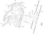
- a pair of parallel spaced tracks 31, 32 are shown secured to the aircraft cabin floor 30 extending longitudinally of the fuselage.
- Tracks 31, 32 may be of the type that are typically installed on an aircraft cabin floor to allow passenger seats to be removably attached to the track rather than directly to the floor.
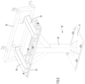
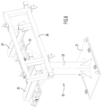
- Base plate 21 is configured with guide members to permit fixture 20 to be moved to different positions along tracks 31, 32 for the purpose of longitudinally positioning the fixture such that its retained support plates 13 are in longitudinal alignment with respective windows 12.
- the support plates 13 are properly positioned opposite their respective windows, the base plate 21 is secured in place relative to tracks 31, 32 by screws, bolts, clamps, latches or other suitable means.
- the support arms 24, 25 may then be slidably extended as necessary to properly position their respective retained panels 13 in close proximity to respective windows 12, after which the support arms are secured in place on the surface of platform 23.
- the panels 13 that are illustrated in the accompanying drawings are relatively large and, when deployed, may block light from passing therethrough into the aircraft cabin. However, that is not to be construed as a limiting factor for the placement of the direction-finding antenna arrays described herein.
- the assumption behind using large panels is that there will be no need for light passage through the covered window when the antenna array is deployed. It should be recognized, however, that for some applications light passage may be desirable and the panels in such cases may be configured to be smaller than the window.
Landscapes
- Physics & Mathematics (AREA)
- Engineering & Computer Science (AREA)
- Astronomy & Astrophysics (AREA)
- Aviation & Aerospace Engineering (AREA)
- General Physics & Mathematics (AREA)
- Remote Sensing (AREA)
- Details Of Aerials (AREA)
Applications Claiming Priority (1)
| Application Number | Priority Date | Filing Date | Title |
|---|---|---|---|
| US18/464,594 US20250087875A1 (en) | 2023-09-11 | 2023-09-11 | Window mountable direction-finding antenna arrays |
Publications (1)
| Publication Number | Publication Date |
|---|---|
| EP4535558A1 true EP4535558A1 (de) | 2025-04-09 |
Family
ID=92295830
Family Applications (1)
| Application Number | Title | Priority Date | Filing Date |
|---|---|---|---|
| EP24193620.2A Pending EP4535558A1 (de) | 2023-09-11 | 2024-08-08 | In fenster montierbare antennengruppen zur richtungsbestimmung |
Country Status (4)
| Country | Link |
|---|---|
| US (1) | US20250087875A1 (de) |
| EP (1) | EP4535558A1 (de) |
| AU (1) | AU2024219533A1 (de) |
| CA (1) | CA3254268A1 (de) |
Citations (3)
| Publication number | Priority date | Publication date | Assignee | Title |
|---|---|---|---|---|
| EP1575128B1 (de) * | 2004-03-09 | 2006-09-20 | Northrop Grumman Corporation | Antennenanordnung für Flugzeugfensteröffnung |
| US10473746B1 (en) * | 2016-12-15 | 2019-11-12 | Bae Systems Information And Electronic Systems Integration Inc. | System and method for rank estimation of electromagnetic emitters |
| EP4063893A1 (de) * | 2021-03-24 | 2022-09-28 | Rockwell Collins, Inc. | Aesa-multifunktionssystem mit mehreren paneelen |
Family Cites Families (2)
| Publication number | Priority date | Publication date | Assignee | Title |
|---|---|---|---|---|
| US10470095B2 (en) * | 2013-01-13 | 2019-11-05 | Qualcomm Incorporated | Method for air-to-ground data link antenna self calibration |
| US11493620B2 (en) * | 2020-02-25 | 2022-11-08 | The Boeing Company | Distributed monopulse radar antenna array for collision avoidance |
-
2023
- 2023-09-11 US US18/464,594 patent/US20250087875A1/en active Pending
-
2024
- 2024-08-08 EP EP24193620.2A patent/EP4535558A1/de active Pending
- 2024-09-06 CA CA3254268A patent/CA3254268A1/en active Pending
- 2024-09-09 AU AU2024219533A patent/AU2024219533A1/en active Pending
Patent Citations (3)
| Publication number | Priority date | Publication date | Assignee | Title |
|---|---|---|---|---|
| EP1575128B1 (de) * | 2004-03-09 | 2006-09-20 | Northrop Grumman Corporation | Antennenanordnung für Flugzeugfensteröffnung |
| US10473746B1 (en) * | 2016-12-15 | 2019-11-12 | Bae Systems Information And Electronic Systems Integration Inc. | System and method for rank estimation of electromagnetic emitters |
| EP4063893A1 (de) * | 2021-03-24 | 2022-09-28 | Rockwell Collins, Inc. | Aesa-multifunktionssystem mit mehreren paneelen |
Also Published As
| Publication number | Publication date |
|---|---|
| US20250087875A1 (en) | 2025-03-13 |
| AU2024219533A1 (en) | 2025-03-27 |
| CA3254268A1 (en) | 2025-05-30 |
Similar Documents
| Publication | Publication Date | Title |
|---|---|---|
| CN111452976B (zh) | 用于在飞行器机舱中布置乘客座椅和乘客服务单元的方法 | |
| AU2013276920B2 (en) | Retainer system for a mobile-telephony antenna and a mobile-telephony component | |
| US6342870B1 (en) | Antenna frame structure mounting and alignment | |
| CN110340823B (zh) | 用于雷达罩安装的外场定位装置 | |
| US10100519B2 (en) | Ceiling system and mounting bracket for use with the same | |
| US20220231397A1 (en) | Automated Feed Source Changer for a Compact Test Range | |
| EP4535558A1 (de) | In fenster montierbare antennengruppen zur richtungsbestimmung | |
| CN102666244B (zh) | 在运输设备舱室中的具有帘子导轨的顶棚镶板 | |
| US11034429B2 (en) | Ceiling header system for aircraft cabin | |
| US20210071906A1 (en) | Method for Mounting Air Outlet Structure of Air Conditioner and Air Outlet Mounting Structure of Air Conditioner | |
| JP7641367B2 (ja) | トランシーバ無線ユニットをセルラ通信システムのコンポーネントに搭載するための装置 | |
| US11923594B2 (en) | Antenna mounting device | |
| US20200172266A1 (en) | Device for fixing cabin side wall paneling and cabin light paneling to a structural component of an aircraft and spacecraft | |
| US5339744A (en) | Baggage rack under flap for the passenger space of a rail vehicle | |
| US8348209B2 (en) | Universal retaining device, particularly for fastening panel elements and/or accessory parts in aircraft | |
| KR102647225B1 (ko) | 안테나 시험 장치 및 방법 | |
| US11128054B2 (en) | Antenna, rear access, line replaceable unit RF panel architecture | |
| CN214041721U (zh) | 一种雷达测试支架 | |
| CN223579393U (zh) | 一种无人机侦测设备的底盘结构 | |
| CN111092599B (zh) | 一种太阳电池板测试架 | |
| EP3389283B1 (de) | Trägergestell für testvorrichtung | |
| CN114639973A (zh) | 等相位集成互联模块 | |
| CN222355436U (zh) | 一种用于射灯天线的调相装置 | |
| CN219123462U (zh) | 天线支架及天线组件 | |
| CN219104322U (zh) | 一种灯具的光学实验装置 |
Legal Events
| Date | Code | Title | Description |
|---|---|---|---|
| PUAI | Public reference made under article 153(3) epc to a published international application that has entered the european phase |
Free format text: ORIGINAL CODE: 0009012 |
|
| STAA | Information on the status of an ep patent application or granted ep patent |
Free format text: STATUS: REQUEST FOR EXAMINATION WAS MADE |
|
| 17P | Request for examination filed |
Effective date: 20240808 |
|
| AK | Designated contracting states |
Kind code of ref document: A1 Designated state(s): AL AT BE BG CH CY CZ DE DK EE ES FI FR GB GR HR HU IE IS IT LI LT LU LV MC ME MK MT NL NO PL PT RO RS SE SI SK SM TR |
|
| GRAP | Despatch of communication of intention to grant a patent |
Free format text: ORIGINAL CODE: EPIDOSNIGR1 |
|
| STAA | Information on the status of an ep patent application or granted ep patent |
Free format text: STATUS: GRANT OF PATENT IS INTENDED |