EP4535537A1 - Batteriemodul, batteriepack und fahrzeug - Google Patents
Batteriemodul, batteriepack und fahrzeug Download PDFInfo
- Publication number
- EP4535537A1 EP4535537A1 EP24746955.4A EP24746955A EP4535537A1 EP 4535537 A1 EP4535537 A1 EP 4535537A1 EP 24746955 A EP24746955 A EP 24746955A EP 4535537 A1 EP4535537 A1 EP 4535537A1
- Authority
- EP
- European Patent Office
- Prior art keywords
- mounting portion
- busbar
- busbar support
- mounting
- positioning
- Prior art date
- Legal status (The legal status is an assumption and is not a legal conclusion. Google has not performed a legal analysis and makes no representation as to the accuracy of the status listed.)
- Pending
Links
Images
Classifications
-
- H—ELECTRICITY
- H01—ELECTRIC ELEMENTS
- H01M—PROCESSES OR MEANS, e.g. BATTERIES, FOR THE DIRECT CONVERSION OF CHEMICAL ENERGY INTO ELECTRICAL ENERGY
- H01M50/00—Constructional details or processes of manufacture of the non-active parts of electrochemical cells other than fuel cells, e.g. hybrid cells
- H01M50/50—Current conducting connections for cells or batteries
- H01M50/502—Interconnectors for connecting terminals of adjacent batteries; Interconnectors for connecting cells outside a battery casing
- H01M50/503—Interconnectors for connecting terminals of adjacent batteries; Interconnectors for connecting cells outside a battery casing characterised by the shape of the interconnectors
-
- H—ELECTRICITY
- H01—ELECTRIC ELEMENTS
- H01M—PROCESSES OR MEANS, e.g. BATTERIES, FOR THE DIRECT CONVERSION OF CHEMICAL ENERGY INTO ELECTRICAL ENERGY
- H01M50/00—Constructional details or processes of manufacture of the non-active parts of electrochemical cells other than fuel cells, e.g. hybrid cells
- H01M50/20—Mountings; Secondary casings or frames; Racks, modules or packs; Suspension devices; Shock absorbers; Transport or carrying devices; Holders
- H01M50/204—Racks, modules or packs for multiple batteries or multiple cells
-
- H—ELECTRICITY
- H01—ELECTRIC ELEMENTS
- H01M—PROCESSES OR MEANS, e.g. BATTERIES, FOR THE DIRECT CONVERSION OF CHEMICAL ENERGY INTO ELECTRICAL ENERGY
- H01M50/00—Constructional details or processes of manufacture of the non-active parts of electrochemical cells other than fuel cells, e.g. hybrid cells
- H01M50/20—Mountings; Secondary casings or frames; Racks, modules or packs; Suspension devices; Shock absorbers; Transport or carrying devices; Holders
- H01M50/244—Secondary casings; Racks; Suspension devices; Carrying devices; Holders characterised by their mounting method
-
- H—ELECTRICITY
- H01—ELECTRIC ELEMENTS
- H01M—PROCESSES OR MEANS, e.g. BATTERIES, FOR THE DIRECT CONVERSION OF CHEMICAL ENERGY INTO ELECTRICAL ENERGY
- H01M50/00—Constructional details or processes of manufacture of the non-active parts of electrochemical cells other than fuel cells, e.g. hybrid cells
- H01M50/20—Mountings; Secondary casings or frames; Racks, modules or packs; Suspension devices; Shock absorbers; Transport or carrying devices; Holders
- H01M50/249—Mountings; Secondary casings or frames; Racks, modules or packs; Suspension devices; Shock absorbers; Transport or carrying devices; Holders specially adapted for aircraft or vehicles, e.g. cars or trains
-
- H—ELECTRICITY
- H01—ELECTRIC ELEMENTS
- H01M—PROCESSES OR MEANS, e.g. BATTERIES, FOR THE DIRECT CONVERSION OF CHEMICAL ENERGY INTO ELECTRICAL ENERGY
- H01M50/00—Constructional details or processes of manufacture of the non-active parts of electrochemical cells other than fuel cells, e.g. hybrid cells
- H01M50/20—Mountings; Secondary casings or frames; Racks, modules or packs; Suspension devices; Shock absorbers; Transport or carrying devices; Holders
- H01M50/258—Modular batteries; Casings provided with means for assembling
-
- H—ELECTRICITY
- H01—ELECTRIC ELEMENTS
- H01M—PROCESSES OR MEANS, e.g. BATTERIES, FOR THE DIRECT CONVERSION OF CHEMICAL ENERGY INTO ELECTRICAL ENERGY
- H01M50/00—Constructional details or processes of manufacture of the non-active parts of electrochemical cells other than fuel cells, e.g. hybrid cells
- H01M50/20—Mountings; Secondary casings or frames; Racks, modules or packs; Suspension devices; Shock absorbers; Transport or carrying devices; Holders
- H01M50/271—Lids or covers for the racks or secondary casings
-
- H—ELECTRICITY
- H01—ELECTRIC ELEMENTS
- H01M—PROCESSES OR MEANS, e.g. BATTERIES, FOR THE DIRECT CONVERSION OF CHEMICAL ENERGY INTO ELECTRICAL ENERGY
- H01M50/00—Constructional details or processes of manufacture of the non-active parts of electrochemical cells other than fuel cells, e.g. hybrid cells
- H01M50/50—Current conducting connections for cells or batteries
- H01M50/502—Interconnectors for connecting terminals of adjacent batteries; Interconnectors for connecting cells outside a battery casing
- H01M50/519—Interconnectors for connecting terminals of adjacent batteries; Interconnectors for connecting cells outside a battery casing comprising printed circuit boards [PCB]
-
- H—ELECTRICITY
- H01—ELECTRIC ELEMENTS
- H01M—PROCESSES OR MEANS, e.g. BATTERIES, FOR THE DIRECT CONVERSION OF CHEMICAL ENERGY INTO ELECTRICAL ENERGY
- H01M2220/00—Batteries for particular applications
- H01M2220/20—Batteries in motive systems, e.g. vehicle, ship, plane
-
- Y—GENERAL TAGGING OF NEW TECHNOLOGICAL DEVELOPMENTS; GENERAL TAGGING OF CROSS-SECTIONAL TECHNOLOGIES SPANNING OVER SEVERAL SECTIONS OF THE IPC; TECHNICAL SUBJECTS COVERED BY FORMER USPC CROSS-REFERENCE ART COLLECTIONS [XRACs] AND DIGESTS
- Y02—TECHNOLOGIES OR APPLICATIONS FOR MITIGATION OR ADAPTATION AGAINST CLIMATE CHANGE
- Y02E—REDUCTION OF GREENHOUSE GAS [GHG] EMISSIONS, RELATED TO ENERGY GENERATION, TRANSMISSION OR DISTRIBUTION
- Y02E60/00—Enabling technologies; Technologies with a potential or indirect contribution to GHG emissions mitigation
- Y02E60/10—Energy storage using batteries
Definitions
- the present disclosure relates to the field of battery technologies, and particularly, to a battery module, a battery pack, and a vehicle.
- a busbar support is usually disposed at a side of the battery module.
- a protection cover of the battery module is assembled corresponding to the busbar support, and the protection cover is also mounted at the side of the battery module, which causes inconvenience in mounting the protection cover. Meanwhile, when the protection cover and the busbar support are mounted at the side of the battery module, it is difficult to ensure the assembly reliability.
- the present disclosure aims to solve one of the technical problems in the related art at least to some extent.
- an object of the present disclosure is to provide a battery module.
- Another object of the present disclosure is to provide a battery pack.
- a further object of the present disclosure is to provide a vehicle.
- inventions of the present disclosure provide a battery module.
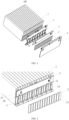
- the battery module includes a plurality of battery cells, a busbar and a busbar support, and a protection cover.
- the busbar is configured to electrically connect two battery cells of the plurality of battery cells and limit a position of the busbar support at the plurality of battery cells.
- the busbar support has a first mounting portion and a second mounting portion.
- the protection cover is located at a side of the busbar support away from the plurality of battery cells.
- the protection cover has a third mounting portion and a fourth mounting portion. The protection cover is fixed to the busbar support by engaging the first mounting portion and the second mounting portion with the third mounting portion and the fourth mounting portion, respectively.
- the first mounting portion and the second mounting portion are provided at the busbar support, and the third mounting portion and the fourth mounting portion are provided at the protection cover.
- the protection cover and the busbar support can be fixedly mounted by means of the engagement between the first mounting portion and the third mounting portion and the engagement between the second mounting portion and the fourth mounting portion. In this way, an assembly process is simple and convenient and has high reliability.
- a battery module 100, a battery pack, and a vehicle according to the embodiments of the present disclosure will be described in detail below with reference to the accompanying drawings.
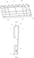
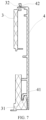
- the busbar support 3 has the first mounting portion 31 and the second mounting portion 32
- the protection cover 4 has the third mounting portion 41 and the fourth mounting portion 42.
- the protection cover 4 is mounted at the side of the busbar support 3 away from the battery cells 1.
- the protection cover 4 when mounting the protection cover 4 onto the busbar support 3, the protection cover 4 is inclined at a certain angle to allow the first mounting portion 31 and the third mounting portion 41 to be engaged, and the protection cover 4 is then rotated towards the busbar support 3 by taking the third mounting portion 41 as an axial direction, to enable the second mounting portion 32 to be engaged with the fourth mounting portion 42.
- FIG. 6 when mounting the protection cover 4 onto the busbar support 3, the protection cover 4 is inclined at a certain angle to allow the first mounting portion 31 and the third mounting portion 41 to be engaged, and the protection cover 4 is then rotated towards the busbar support 3 by taking the third mounting portion 41 as an axial direction, to enable the second mounting portion 32 to be engaged with the fourth mounting portion 42.
- the protection cover 4 and the busbar support 3 can be fixed mounted based on the engagement between the first mounting portion 31 and the third mounting portion 41 and the engagement between the second mounting portion 32 and the fourth mounting portion 42.
- the entire mounting process is simple and convenient.
- the first mounting portion 31 and the third mounting portion 41 as well as the second mounting portion 32 and the fourth mounting portion 42 can be tightly mounted, thereby ensuring assembly reliability between the protection cover 4 and the busbar support 3.
- one of the first mounting portion 31 and the third mounting portion 41 is a positioning groove, and the other one of the first mounting portion 31 and the third mounting portion 41 is a positioning protrusion.
- the positioning protrusion is mounted in the positioning groove.
- the protection cover 4 when assembling the protection cover 4 and the busbar support 3, the protection cover 4 is inclined at a certain angle, to engage and assemble the positioning protrusion of the busbar support 3 with the positioning groove of the protection cover 4, allowing the positioning protrusion to be mounted in the positioning groove.
- the positioning protrusion abuts against an inner wall of the positioning groove. In this way, the protection cover 4 can be mounted on the busbar support 3, and the position of the protection cover 4 and the busbar support 3 can be quickly limited, thereby improving assembly efficiency.
- a plurality of first mounting portions 31, a plurality of second mounting portions 32, a plurality of third mounting portions 41, and a plurality of fourth mounting portions 42 are provided.
- the plurality of first mounting portions 31 corresponds to the plurality of third mounting portions 41 in one-to-one correspondence.
- the plurality of second mounting portions 32 corresponds to the plurality of fourth mounting portions 42 in one-to-one correspondence.
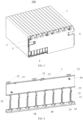
- the busbar support 3 further includes a plurality of first positioning members 34.
- the first positioning member 34 is correspondingly disposed to the limiting surface located at the lower portion of the first positioning hole 33.
- each limiting surface is provided with two first positioning members 34.
- the first positioning member 34 may be a positioning pin, a positioning column, or a positioning protrusion, which is not specifically limited herein.
- Each busbar 2 correspondingly has a second positioning hole 21. The number of the second positioning holes 21 is consistent with the number of the first positioning members 34 arranged at each limiting surface. As illustrated in FIG. 2 , each busbar 2 has two second positioning holes 21.
- the battery module further includes a circuit board 5 fixed to the busbar support 3.
- some components such as wirings and sensors are disposed inside the battery module 100, and these components are usually disposed on the circuit board 5. Therefore, the circuit board 5 is required to be mounted on the busbar support 3, in order to obtain an operation state of the battery cells 1 inside the battery and improve a battery operation management level.
- the battery pack according to the embodiments of the second aspect of the present disclosure includes the battery module 100 according to the embodiment of the first aspect.
Landscapes
- Chemical & Material Sciences (AREA)
- Chemical Kinetics & Catalysis (AREA)
- Electrochemistry (AREA)
- General Chemical & Material Sciences (AREA)
- Engineering & Computer Science (AREA)
- Aviation & Aerospace Engineering (AREA)
- Battery Mounting, Suspending (AREA)
- Connection Of Batteries Or Terminals (AREA)
Applications Claiming Priority (2)
| Application Number | Priority Date | Filing Date | Title |
|---|---|---|---|
| CN202320196315.2U CN219643022U (zh) | 2023-01-28 | 2023-01-28 | 电池模组、电池包及车辆 |
| PCT/CN2024/070193 WO2024156248A1 (zh) | 2023-01-28 | 2024-01-02 | 电池模组、电池包及车辆 |
Publications (2)
| Publication Number | Publication Date |
|---|---|
| EP4535537A1 true EP4535537A1 (de) | 2025-04-09 |
| EP4535537A4 EP4535537A4 (de) | 2026-04-01 |
Family
ID=87810150
Family Applications (1)
| Application Number | Title | Priority Date | Filing Date |
|---|---|---|---|
| EP24746955.4A Pending EP4535537A4 (de) | 2023-01-28 | 2024-01-02 | Batteriemodul, batteriepack und fahrzeug |
Country Status (5)
| Country | Link |
|---|---|
| US (1) | US20250210818A1 (de) |
| EP (1) | EP4535537A4 (de) |
| JP (1) | JP2025525649A (de) |
| CN (1) | CN219643022U (de) |
| WO (1) | WO2024156248A1 (de) |
Families Citing this family (1)
| Publication number | Priority date | Publication date | Assignee | Title |
|---|---|---|---|---|
| CN219643022U (zh) * | 2023-01-28 | 2023-09-05 | 浙江极氪智能科技有限公司 | 电池模组、电池包及车辆 |
Family Cites Families (7)
| Publication number | Priority date | Publication date | Assignee | Title |
|---|---|---|---|---|
| DE102004063982A1 (de) * | 2004-11-09 | 2006-06-14 | Lumberg Connect Gmbh & Co. Kg | Kontaktiervorrichtung für eine Chipkarte, insbesondere für eine SIM-Karte |
| KR101839146B1 (ko) * | 2011-06-03 | 2018-03-16 | 삼성전자주식회사 | 커버 부재 결합 장치 및 그를 이용한 배터리 커버 결합 구조를 구비하는 휴대용 단말기 |
| CN102956857B (zh) * | 2012-12-04 | 2014-11-19 | 江苏惠通集团有限责任公司 | 控制器电池仓盖板装置 |
| CN208489250U (zh) * | 2018-05-18 | 2019-02-12 | 蜂巢能源科技有限公司 | 用于车辆的电池模组 |
| CN210200771U (zh) * | 2019-09-29 | 2020-03-27 | 蜂巢能源科技有限公司 | 上盖组件、电池模组及电池包 |
| JP6937350B2 (ja) * | 2019-11-07 | 2021-09-22 | 株式会社オートネットワーク技術研究所 | 蓄電モジュール |
| CN219643022U (zh) * | 2023-01-28 | 2023-09-05 | 浙江极氪智能科技有限公司 | 电池模组、电池包及车辆 |
-
2023
- 2023-01-28 CN CN202320196315.2U patent/CN219643022U/zh active Active
-
2024
- 2024-01-02 EP EP24746955.4A patent/EP4535537A4/de active Pending
- 2024-01-02 WO PCT/CN2024/070193 patent/WO2024156248A1/zh not_active Ceased
- 2024-01-02 JP JP2025504366A patent/JP2025525649A/ja active Pending
-
2025
- 2025-03-11 US US19/076,954 patent/US20250210818A1/en active Pending
Also Published As
| Publication number | Publication date |
|---|---|
| US20250210818A1 (en) | 2025-06-26 |
| EP4535537A4 (de) | 2026-04-01 |
| WO2024156248A1 (zh) | 2024-08-02 |
| JP2025525649A (ja) | 2025-08-05 |
| CN219643022U (zh) | 2023-09-05 |
Similar Documents
| Publication | Publication Date | Title |
|---|---|---|
| JP6640338B2 (ja) | 電池モジュール | |
| US20210066700A1 (en) | Single-cell battery, battery module, power battery and electric vehicle | |
| US10601082B2 (en) | Signal collection assembly and power battery module comprising the same | |
| US20250210818A1 (en) | Battery module, battery pack and vehicle | |
| KR20230031661A (ko) | 버스바 플레이트와 icb 조립체 간의 와이어 본딩 연결 구조를 개선한 배터리 모듈 및 이를 포함하는 배터리 팩 | |
| US12113241B2 (en) | Battery module | |
| WO2020258370A1 (zh) | 电池模组 | |
| CN213483886U (zh) | 一种电池包及车辆 | |
| CN116315506B (zh) | 一种电池组件、电池包 | |
| CN115566369A (zh) | 电池模组 | |
| CN221009170U (zh) | 一种装配式电池模组汇流排结构 | |
| EP4365921A1 (de) | Kondensatormodul und motorwechselrichter | |
| CN217468609U (zh) | 一种电池模组装置及电动车辆 | |
| CN108336271A (zh) | 一种电动汽车的动力电池 | |
| US20210359356A1 (en) | Battery module | |
| CN221828091U (zh) | Ccs集成组件及电池包 | |
| CN215644769U (zh) | 电池模组的外壳及电池模组 | |
| CN220042095U (zh) | 固定支架和电池模组 | |
| CN219759880U (zh) | 电池模组 | |
| CN221379589U (zh) | 端板组件和具有其的电池 | |
| CN224067838U (zh) | 一种新型分体式ccs采集模组及储能电池柜 | |
| CN220585337U (zh) | 顶盖组件 | |
| CN219832968U (zh) | 电池模组采样结构及电池模组 | |
| CN223987222U (zh) | 一种电路板组件安装结构 | |
| CN222654137U (zh) | 一种电池包 |
Legal Events
| Date | Code | Title | Description |
|---|---|---|---|
| STAA | Information on the status of an ep patent application or granted ep patent |
Free format text: STATUS: THE INTERNATIONAL PUBLICATION HAS BEEN MADE |
|
| PUAI | Public reference made under article 153(3) epc to a published international application that has entered the european phase |
Free format text: ORIGINAL CODE: 0009012 |
|
| STAA | Information on the status of an ep patent application or granted ep patent |
Free format text: STATUS: REQUEST FOR EXAMINATION WAS MADE |
|
| 17P | Request for examination filed |
Effective date: 20250103 |
|
| AK | Designated contracting states |
Kind code of ref document: A1 Designated state(s): AL AT BE BG CH CY CZ DE DK EE ES FI FR GB GR HR HU IE IS IT LI LT LU LV MC ME MK MT NL NO PL PT RO RS SE SI SK SM TR |