EP4535537A1 - Battery module, battery pack and vehicle - Google Patents
Battery module, battery pack and vehicle Download PDFInfo
- Publication number
- EP4535537A1 EP4535537A1 EP24746955.4A EP24746955A EP4535537A1 EP 4535537 A1 EP4535537 A1 EP 4535537A1 EP 24746955 A EP24746955 A EP 24746955A EP 4535537 A1 EP4535537 A1 EP 4535537A1
- Authority
- EP
- European Patent Office
- Prior art keywords
- mounting portion
- busbar
- busbar support
- mounting
- positioning
- Prior art date
- Legal status (The legal status is an assumption and is not a legal conclusion. Google has not performed a legal analysis and makes no representation as to the accuracy of the status listed.)
- Pending
Links
Images
Classifications
-
- H—ELECTRICITY
- H01—ELECTRIC ELEMENTS
- H01M—PROCESSES OR MEANS, e.g. BATTERIES, FOR THE DIRECT CONVERSION OF CHEMICAL ENERGY INTO ELECTRICAL ENERGY
- H01M50/00—Constructional details or processes of manufacture of the non-active parts of electrochemical cells other than fuel cells, e.g. hybrid cells
- H01M50/50—Current conducting connections for cells or batteries
- H01M50/502—Interconnectors for connecting terminals of adjacent batteries; Interconnectors for connecting cells outside a battery casing
- H01M50/503—Interconnectors for connecting terminals of adjacent batteries; Interconnectors for connecting cells outside a battery casing characterised by the shape of the interconnectors
-
- H—ELECTRICITY
- H01—ELECTRIC ELEMENTS
- H01M—PROCESSES OR MEANS, e.g. BATTERIES, FOR THE DIRECT CONVERSION OF CHEMICAL ENERGY INTO ELECTRICAL ENERGY
- H01M50/00—Constructional details or processes of manufacture of the non-active parts of electrochemical cells other than fuel cells, e.g. hybrid cells
- H01M50/20—Mountings; Secondary casings or frames; Racks, modules or packs; Suspension devices; Shock absorbers; Transport or carrying devices; Holders
- H01M50/204—Racks, modules or packs for multiple batteries or multiple cells
-
- H—ELECTRICITY
- H01—ELECTRIC ELEMENTS
- H01M—PROCESSES OR MEANS, e.g. BATTERIES, FOR THE DIRECT CONVERSION OF CHEMICAL ENERGY INTO ELECTRICAL ENERGY
- H01M50/00—Constructional details or processes of manufacture of the non-active parts of electrochemical cells other than fuel cells, e.g. hybrid cells
- H01M50/20—Mountings; Secondary casings or frames; Racks, modules or packs; Suspension devices; Shock absorbers; Transport or carrying devices; Holders
- H01M50/244—Secondary casings; Racks; Suspension devices; Carrying devices; Holders characterised by their mounting method
-
- H—ELECTRICITY
- H01—ELECTRIC ELEMENTS
- H01M—PROCESSES OR MEANS, e.g. BATTERIES, FOR THE DIRECT CONVERSION OF CHEMICAL ENERGY INTO ELECTRICAL ENERGY
- H01M50/00—Constructional details or processes of manufacture of the non-active parts of electrochemical cells other than fuel cells, e.g. hybrid cells
- H01M50/20—Mountings; Secondary casings or frames; Racks, modules or packs; Suspension devices; Shock absorbers; Transport or carrying devices; Holders
- H01M50/249—Mountings; Secondary casings or frames; Racks, modules or packs; Suspension devices; Shock absorbers; Transport or carrying devices; Holders specially adapted for aircraft or vehicles, e.g. cars or trains
-
- H—ELECTRICITY
- H01—ELECTRIC ELEMENTS
- H01M—PROCESSES OR MEANS, e.g. BATTERIES, FOR THE DIRECT CONVERSION OF CHEMICAL ENERGY INTO ELECTRICAL ENERGY
- H01M50/00—Constructional details or processes of manufacture of the non-active parts of electrochemical cells other than fuel cells, e.g. hybrid cells
- H01M50/20—Mountings; Secondary casings or frames; Racks, modules or packs; Suspension devices; Shock absorbers; Transport or carrying devices; Holders
- H01M50/258—Modular batteries; Casings provided with means for assembling
-
- H—ELECTRICITY
- H01—ELECTRIC ELEMENTS
- H01M—PROCESSES OR MEANS, e.g. BATTERIES, FOR THE DIRECT CONVERSION OF CHEMICAL ENERGY INTO ELECTRICAL ENERGY
- H01M50/00—Constructional details or processes of manufacture of the non-active parts of electrochemical cells other than fuel cells, e.g. hybrid cells
- H01M50/20—Mountings; Secondary casings or frames; Racks, modules or packs; Suspension devices; Shock absorbers; Transport or carrying devices; Holders
- H01M50/271—Lids or covers for the racks or secondary casings
-
- H—ELECTRICITY
- H01—ELECTRIC ELEMENTS
- H01M—PROCESSES OR MEANS, e.g. BATTERIES, FOR THE DIRECT CONVERSION OF CHEMICAL ENERGY INTO ELECTRICAL ENERGY
- H01M50/00—Constructional details or processes of manufacture of the non-active parts of electrochemical cells other than fuel cells, e.g. hybrid cells
- H01M50/50—Current conducting connections for cells or batteries
- H01M50/502—Interconnectors for connecting terminals of adjacent batteries; Interconnectors for connecting cells outside a battery casing
- H01M50/519—Interconnectors for connecting terminals of adjacent batteries; Interconnectors for connecting cells outside a battery casing comprising printed circuit boards [PCB]
-
- H—ELECTRICITY
- H01—ELECTRIC ELEMENTS
- H01M—PROCESSES OR MEANS, e.g. BATTERIES, FOR THE DIRECT CONVERSION OF CHEMICAL ENERGY INTO ELECTRICAL ENERGY
- H01M2220/00—Batteries for particular applications
- H01M2220/20—Batteries in motive systems, e.g. vehicle, ship, plane
-
- Y—GENERAL TAGGING OF NEW TECHNOLOGICAL DEVELOPMENTS; GENERAL TAGGING OF CROSS-SECTIONAL TECHNOLOGIES SPANNING OVER SEVERAL SECTIONS OF THE IPC; TECHNICAL SUBJECTS COVERED BY FORMER USPC CROSS-REFERENCE ART COLLECTIONS [XRACs] AND DIGESTS
- Y02—TECHNOLOGIES OR APPLICATIONS FOR MITIGATION OR ADAPTATION AGAINST CLIMATE CHANGE
- Y02E—REDUCTION OF GREENHOUSE GAS [GHG] EMISSIONS, RELATED TO ENERGY GENERATION, TRANSMISSION OR DISTRIBUTION
- Y02E60/00—Enabling technologies; Technologies with a potential or indirect contribution to GHG emissions mitigation
- Y02E60/10—Energy storage using batteries
Definitions
- the present disclosure relates to the field of battery technologies, and particularly, to a battery module, a battery pack, and a vehicle.
- a busbar support is usually disposed at a side of the battery module.
- a protection cover of the battery module is assembled corresponding to the busbar support, and the protection cover is also mounted at the side of the battery module, which causes inconvenience in mounting the protection cover. Meanwhile, when the protection cover and the busbar support are mounted at the side of the battery module, it is difficult to ensure the assembly reliability.
- the present disclosure aims to solve one of the technical problems in the related art at least to some extent.
- an object of the present disclosure is to provide a battery module.
- Another object of the present disclosure is to provide a battery pack.
- a further object of the present disclosure is to provide a vehicle.
- inventions of the present disclosure provide a battery module.
- the battery module includes a plurality of battery cells, a busbar and a busbar support, and a protection cover.
- the busbar is configured to electrically connect two battery cells of the plurality of battery cells and limit a position of the busbar support at the plurality of battery cells.
- the busbar support has a first mounting portion and a second mounting portion.
- the protection cover is located at a side of the busbar support away from the plurality of battery cells.
- the protection cover has a third mounting portion and a fourth mounting portion. The protection cover is fixed to the busbar support by engaging the first mounting portion and the second mounting portion with the third mounting portion and the fourth mounting portion, respectively.
- the first mounting portion and the second mounting portion are provided at the busbar support, and the third mounting portion and the fourth mounting portion are provided at the protection cover.
- the protection cover and the busbar support can be fixedly mounted by means of the engagement between the first mounting portion and the third mounting portion and the engagement between the second mounting portion and the fourth mounting portion. In this way, an assembly process is simple and convenient and has high reliability.
- a battery module 100, a battery pack, and a vehicle according to the embodiments of the present disclosure will be described in detail below with reference to the accompanying drawings.
- the busbar support 3 has the first mounting portion 31 and the second mounting portion 32
- the protection cover 4 has the third mounting portion 41 and the fourth mounting portion 42.
- the protection cover 4 is mounted at the side of the busbar support 3 away from the battery cells 1.
- the protection cover 4 when mounting the protection cover 4 onto the busbar support 3, the protection cover 4 is inclined at a certain angle to allow the first mounting portion 31 and the third mounting portion 41 to be engaged, and the protection cover 4 is then rotated towards the busbar support 3 by taking the third mounting portion 41 as an axial direction, to enable the second mounting portion 32 to be engaged with the fourth mounting portion 42.
- FIG. 6 when mounting the protection cover 4 onto the busbar support 3, the protection cover 4 is inclined at a certain angle to allow the first mounting portion 31 and the third mounting portion 41 to be engaged, and the protection cover 4 is then rotated towards the busbar support 3 by taking the third mounting portion 41 as an axial direction, to enable the second mounting portion 32 to be engaged with the fourth mounting portion 42.
- the protection cover 4 and the busbar support 3 can be fixed mounted based on the engagement between the first mounting portion 31 and the third mounting portion 41 and the engagement between the second mounting portion 32 and the fourth mounting portion 42.
- the entire mounting process is simple and convenient.
- the first mounting portion 31 and the third mounting portion 41 as well as the second mounting portion 32 and the fourth mounting portion 42 can be tightly mounted, thereby ensuring assembly reliability between the protection cover 4 and the busbar support 3.
- one of the first mounting portion 31 and the third mounting portion 41 is a positioning groove, and the other one of the first mounting portion 31 and the third mounting portion 41 is a positioning protrusion.
- the positioning protrusion is mounted in the positioning groove.
- the protection cover 4 when assembling the protection cover 4 and the busbar support 3, the protection cover 4 is inclined at a certain angle, to engage and assemble the positioning protrusion of the busbar support 3 with the positioning groove of the protection cover 4, allowing the positioning protrusion to be mounted in the positioning groove.
- the positioning protrusion abuts against an inner wall of the positioning groove. In this way, the protection cover 4 can be mounted on the busbar support 3, and the position of the protection cover 4 and the busbar support 3 can be quickly limited, thereby improving assembly efficiency.
- a plurality of first mounting portions 31, a plurality of second mounting portions 32, a plurality of third mounting portions 41, and a plurality of fourth mounting portions 42 are provided.
- the plurality of first mounting portions 31 corresponds to the plurality of third mounting portions 41 in one-to-one correspondence.
- the plurality of second mounting portions 32 corresponds to the plurality of fourth mounting portions 42 in one-to-one correspondence.
- the busbar support 3 further includes a plurality of first positioning members 34.
- the first positioning member 34 is correspondingly disposed to the limiting surface located at the lower portion of the first positioning hole 33.
- each limiting surface is provided with two first positioning members 34.
- the first positioning member 34 may be a positioning pin, a positioning column, or a positioning protrusion, which is not specifically limited herein.
- Each busbar 2 correspondingly has a second positioning hole 21. The number of the second positioning holes 21 is consistent with the number of the first positioning members 34 arranged at each limiting surface. As illustrated in FIG. 2 , each busbar 2 has two second positioning holes 21.
- the battery module further includes a circuit board 5 fixed to the busbar support 3.
- some components such as wirings and sensors are disposed inside the battery module 100, and these components are usually disposed on the circuit board 5. Therefore, the circuit board 5 is required to be mounted on the busbar support 3, in order to obtain an operation state of the battery cells 1 inside the battery and improve a battery operation management level.
- the battery pack according to the embodiments of the second aspect of the present disclosure includes the battery module 100 according to the embodiment of the first aspect.
Landscapes
- Chemical & Material Sciences (AREA)
- Chemical Kinetics & Catalysis (AREA)
- Electrochemistry (AREA)
- General Chemical & Material Sciences (AREA)
- Engineering & Computer Science (AREA)
- Aviation & Aerospace Engineering (AREA)
- Battery Mounting, Suspending (AREA)
- Connection Of Batteries Or Terminals (AREA)
Abstract
Description
- This application is based on and claims a priority to
Chinese Patent Application No. 202320196315.2, filed on January 28, 2023 - The present disclosure relates to the field of battery technologies, and particularly, to a battery module, a battery pack, and a vehicle.
- In the related art, for a battery module in which a battery cell is horizontally placed, for example, a blade battery, a busbar support is usually disposed at a side of the battery module. A protection cover of the battery module is assembled corresponding to the busbar support, and the protection cover is also mounted at the side of the battery module, which causes inconvenience in mounting the protection cover. Meanwhile, when the protection cover and the busbar support are mounted at the side of the battery module, it is difficult to ensure the assembly reliability.
- The present disclosure aims to solve one of the technical problems in the related art at least to some extent.
- To this end, an object of the present disclosure is to provide a battery module.
- Another object of the present disclosure is to provide a battery pack.
- A further object of the present disclosure is to provide a vehicle.
- To achieve the above object, in a first aspect, embodiments of the present disclosure provide a battery module. The battery module includes a plurality of battery cells, a busbar and a busbar support, and a protection cover. The busbar is configured to electrically connect two battery cells of the plurality of battery cells and limit a position of the busbar support at the plurality of battery cells. The busbar support has a first mounting portion and a second mounting portion. The protection cover is located at a side of the busbar support away from the plurality of battery cells. The protection cover has a third mounting portion and a fourth mounting portion. The protection cover is fixed to the busbar support by engaging the first mounting portion and the second mounting portion with the third mounting portion and the fourth mounting portion, respectively.
- In the battery module according to the embodiments of the present disclosure, the first mounting portion and the second mounting portion are provided at the busbar support, and the third mounting portion and the fourth mounting portion are provided at the protection cover. The protection cover and the busbar support can be fixedly mounted by means of the engagement between the first mounting portion and the third mounting portion and the engagement between the second mounting portion and the fourth mounting portion. In this way, an assembly process is simple and convenient and has high reliability.
- To achieve the above object, in a second aspect, the embodiments of the present disclosure provide a battery pack. The battery pack includes the battery module according to the embodiments of the first aspect.
- In the battery pack according to the embodiments of the present disclosure, the first mounting portion and the second mounting portion are provided at the busbar support, and the third mounting portion and the fourth mounting portion are provided at the protection cover. The protection cover and the busbar support can be fixedly mounted by means of the engagement between the first mounting portion and the third mounting portion and the engagement between the second mounting portion and the fourth mounting portion. In this way, an assembly process is simple and convenient and has high reliability.
- To achieve the above object, in a third aspect, the embodiments of the present disclosure provide a vehicle. The vehicle includes the battery pack according to the embodiment of the second aspect.
- In the vehicle according to the embodiment of the present disclosure, by providing the battery pack, the first mounting portion and the second mounting portion are provided at the busbar support, and the third mounting portion and the fourth mounting portion are provided at the protection cover. The protection cover and the busbar support can be fixedly mounted by means of the engagement between the first mounting portion and the third mounting portion and the engagement between the second mounting portion and the fourth mounting portion. In this way, an assembly process is simple and convenient and has high reliability.
- Additional aspects and advantages of the embodiments of the present disclosure will be given at least in part in the following description, or become apparent at least in part from the following description, or can be learned from practicing of the embodiments of the present disclosure.
-
-
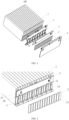
FIG. 1 is an exploded view of a battery module according to an embodiment of the present disclosure. -
FIG. 2 is a schematic view of a battery cell, a busbar, a busbar support, and a circuit board according to an embodiment of the present disclosure. -
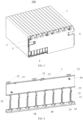
FIG. 3 is an assembly view of a battery module according to an embodiment of the present disclosure. -
FIG. 4 is a perspective view of busbar support according to an embodiment of the present disclosure. -
FIG. 5 is a perspective view of a protection cover according to an embodiment of the present disclosure. -
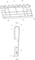
FIG. 6 is a sectional view of a busbar support and a protection cover in an assembly process according to an embodiment of the present disclosure. -
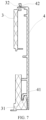
FIG. 7 is a sectional view of a busbar support and a protection cover after assembly according to an embodiment of the present disclosure. - Embodiments of the present disclosure will be described in detail below with reference to examples thereof as illustrated in the accompanying drawings, throughout which same or similar elements, or elements having same or similar functions, are denoted by same or similar reference numerals. The embodiments described below with reference to the drawings are illustrative only and intended to explain, rather than limiting, the present disclosure.
- A
battery module 100, a battery pack, and a vehicle according to the embodiments of the present disclosure will be described in detail below with reference to the accompanying drawings. - As illustrated in
FIG. 1 to FIG. 7 , according to the embodiments of a first aspect of the present disclosure, thebattery module 100 includes a plurality of battery cells 1, abusbar 2, abusbar support 3, and aprotection cover 4. Thebusbar 2 is configured to electrically connect two battery cells 1 and limit a position of thebusbar support 3 at the plurality of battery cells 1. Thebusbar support 3 has afirst mounting portion 31 and asecond mounting portion 32. Theprotection cover 4 is located at a side of thebusbar support 3 away from the plurality of battery cells 1. Theprotection cover 4 has athird mounting portion 41 and afourth mounting portion 42. Theprotection cover 4 is fixed to thebusbar support 3 by engaging thefirst mounting portion 31 and thesecond mounting portion 32 with thethird mounting portion 41 and thefourth mounting portion 42, respectively. - In an embodiment of the present disclosure, as illustrated in
FIG. 1 , thebattery module 100 includes the plurality of battery cells 1, and the plurality of battery cells 1 is horizontally arranged in sequence. Further, as illustrated inFIG. 2 , a plurality ofbusbars 2 is provided, and eachbusbar 2 is configured to electrically connect two adjacent battery cells 1. In this way, the plurality of battery cells 1 can be connected in series by means of thebusbars 2. It should be noted that thebusbars 2 and thebusbar 3 are preassembled before thebusbars 2 are electrically connected to the battery cells 1. Thebusbars 2 are preassembled at the side of thebusbar support 3 away from the battery cells 1. After thebusbars 2 and thebusbar support 3 are preassembled, thebusbars 2 is welded to the corresponding battery cells 1. Thereafter, the position of thebusbar support 3 is limited between the battery cells 1 and thebusbars 2, enabling thebusbar support 3 to be fixedly mounted. - Further, as illustrated in
FIG. 4 to FIG. 7 , thebusbar support 3 has thefirst mounting portion 31 and thesecond mounting portion 32, and theprotection cover 4 has thethird mounting portion 41 and thefourth mounting portion 42. Theprotection cover 4 is mounted at the side of thebusbar support 3 away from the battery cells 1. As illustrated inFIG. 6 , when mounting theprotection cover 4 onto thebusbar support 3, theprotection cover 4 is inclined at a certain angle to allow thefirst mounting portion 31 and thethird mounting portion 41 to be engaged, and theprotection cover 4 is then rotated towards thebusbar support 3 by taking thethird mounting portion 41 as an axial direction, to enable thesecond mounting portion 32 to be engaged with thefourth mounting portion 42. As illustrated inFIG. 7 , theprotection cover 4 and thebusbar support 3 can be fixed mounted based on the engagement between thefirst mounting portion 31 and thethird mounting portion 41 and the engagement between thesecond mounting portion 32 and thefourth mounting portion 42. The entire mounting process is simple and convenient. Thefirst mounting portion 31 and thethird mounting portion 41 as well as thesecond mounting portion 32 and thefourth mounting portion 42 can be tightly mounted, thereby ensuring assembly reliability between theprotection cover 4 and thebusbar support 3. - In the
battery module 100 according to the embodiments of the present disclosure, by providing the first mountingportion 31 and the second mountingportion 32 on thebusbar support 3 and providing the third mountingportion 41 and the fourth mountingportion 42 on theprotection cover 4, theprotection cover 4 and thebusbar support 3 can be fixed mounted based on the engagement between the first mountingportion 31 and the third mountingportion 41 and the engagement between the second mountingportion 32 and the fourth mountingportion 42. The assembly process is simple and convenient and has high reliability. - In some embodiments of the present disclosure, one of the first mounting
portion 31 and the third mountingportion 41 is a positioning groove, and the other one of the first mountingportion 31 and the third mountingportion 41 is a positioning protrusion. The positioning protrusion is mounted in the positioning groove. - In an embodiment of the present disclosure, one of the first mounting
portion 31 and the third mountingportion 41 is provided as the positioning groove, while the other one of the first mountingportion 31 and the third mountingportion 41 is provided as the positioning protrusion. That is, when the first mountingportion 31 is the positioning groove, the third mountingportion 41 is the positioning protrusion; and when the first mountingportion 31 is the positioning protrusion, the third mountingportion 41 is the positioning groove. Further, as illustrated inFIG. 4 to FIG. 7 , as an example, the first mountingportion 31 is the positioning protrusion and the third mountingportion 41 is the positioning groove. As illustrated inFIG. 6 , when assembling theprotection cover 4 and thebusbar support 3, theprotection cover 4 is inclined at a certain angle, to engage and assemble the positioning protrusion of thebusbar support 3 with the positioning groove of theprotection cover 4, allowing the positioning protrusion to be mounted in the positioning groove. The positioning protrusion abuts against an inner wall of the positioning groove. In this way, theprotection cover 4 can be mounted on thebusbar support 3, and the position of theprotection cover 4 and thebusbar support 3 can be quickly limited, thereby improving assembly efficiency. - In some embodiments of the present disclosure, one of the second mounting
portion 32 and the fourth mountingportion 42 is a first mounting hole, and the other one of the second mountingportion 32 and the fourth mountingportion 42 is a first buckle portion. The first buckle portion is adapted to engage with the first mounting hole. - In an embodiment of the present disclosure, one of the second mounting
portion 32 and the fourth mountingportion 42 is provided as the first mounting hole, and the other of the second mountingportion 32 and the fourth mountingportion 42 is provided as the first buckle portion. That is, when the second mountingportion 32 is the first mounting hole, the fourth mountingportion 42 is the first buckle portion; and when the second mountingportion 32 is the first buckle portion, the fourth mountingportion 42 is the first mounting hole. Further, as illustrated inFIG. 4 to FIG. 7 , as an example, the second mountingportion 32 is the first mounting hole and the fourth mountingportion 42 is the first buckle portion. When assembling theprotection cover 4 and thebusbar support 3, theprotection cover 4 is inclined at a certain angle to engage and assemble the first mountingportion 31 with the second mountingportion 32. It should be noted that thebusbar support 3 further has asupport platform 38. During the engaging and assembling of the first mountingportion 31 and the second mountingportion 32, thesupport platform 38 can provide support for theprotection cover 4. Then, by taking the third mountingportion 41 as an axial direction, theprotection cover 4 is rotated towards thebusbar support 3 to allow the first buckle portion to gradually approach the first mounting hole, until a buckle of the first buckle portion passes through the first mounting hole and is engaged with a side of thebusbar support 3 close to the battery cell 1. Therefore, theprotection cover 4 can be tightly mounted at thebusbar support 3 through the engagement between the first buckle portion and the first mounting hole, thereby improving assembly reliability of theprotection cover 4 and thebusbar support 3. - In some embodiments of the present disclosure, as illustrated in
FIG. 4 andFIG. 5 , a plurality of first mountingportions 31, a plurality of second mountingportions 32, a plurality of third mountingportions 41, and a plurality of fourth mountingportions 42 are provided. The plurality of first mountingportions 31 corresponds to the plurality of third mountingportions 41 in one-to-one correspondence. The plurality of second mountingportions 32 corresponds to the plurality of fourth mountingportions 42 in one-to-one correspondence. - In an embodiment of the present disclosure, the number of the first mounting
portion 31, the number of the second mountingportion 32, the number of the third mountingportion 41, and the number of the fourth mountingportion 42 are set according to specific requirements, which are not specifically limited herein. In addition, when assembling theprotection cover 4 and thebusbar support 3, it is ensured that the plurality of first mountingportions 31 and the plurality of third mountingportions 41 are assembled in a one-to-one correspondence, and it is ensured that the plurality of second mountingportions 32 and the plurality of fourth mountingportions 42 are assembled in a one-to-one correspondence. Thus, by providing the plurality of first mountingportions 31, the plurality of second mountingportions 32, the plurality of third mountingportions 41, and the plurality of fourth mountingportions 42, theprotection cover 4 can be more tightly mounted on thebusbar support 3, thereby further improving the assembly reliability of theprotection cover 4 and thebusbar support 3. - In some embodiments of the present disclosure, as illustrated in
FIG. 2 andFIG. 4 , thebusbar support 3 has a plurality of first positioning holes 33. Each battery cell 1 has anelectrode column 11. Theelectrode column 11 of the battery cell 1 is assembled in a correspondingfirst positioning hole 33. Thebusbar 2 is located at the side of thebusbar support 3 away from the battery cells 1 and connected between theelectrode columns 11 of two battery cells 1. - In an embodiment of the present disclosure, as illustrated in
FIG. 2 , each battery cell 1 has theelectrode column 11, and an end surface of theelectrode column 11 is vertically arranged. Thebusbar support 3 has the plurality of first positioning holes 33, and eachfirst positioning hole 33 corresponds to and are matched with theelectrode columns 11 of two adjacent battery cells 1. That is, every twoadjacent electrode columns 11 are assembled fitted in one samefirst positioning hole 33. Further, eachfirst positioning hole 33 has a limiting surface provided at a lower portion of thefirst positioning hole 33. Thebusbar 2 is engaged with thefirst positioning hole 33, and a side of thebusbar 2 close to the battery cell 1 abuts against the limiting surface, allowing thebusbar 2 to be preassembled at the side of thebusbar support 3 away from the battery cells 1. After thebusbar 2 is preassembled with thebusbar support 3, thebusbar 2 is welded to twoadjacent electrode columns 11, and thereafter, thebusbar support 3 is limited between the battery cells 1 and thebusbar 2, thereby realizing the fixed mounting of thebusbar support 3. - In some embodiments of the present disclosure, as illustrated in
FIG. 2 , thefirst positioning hole 33 has an inner side wall abutting against the correspondingelectrode column 11. - In an embodiment of the present disclosure, each
first positioning hole 33 corresponds to and is matched with theelectrode columns 11 of two adjacent battery cells 1. The inner side wall of thefirst positioning hole 33 abuts against the correspondingelectrode columns 11 to allow thebusbar support 3 to be positioned by means of the battery cell 1 and thefirst positioning hole 33, thereby improving the assembly efficiency of thebusbar 2 and thebusbar support 3. In addition, the inner side wall of thefirst positioning hole 33 abuts against theelectrode columns 11, and thus theelectrode column 11 can provide support for thebusbar support 3 in a vertical direction, facilitating an integral assembly of thebusbar support 3 and thebusbar 2 with the battery cells 1. - In some embodiments of the present disclosure, as illustrated in
FIG. 2 andFIG. 4 , thebusbar support 3 further includes afirst positioning member 34. Thebusbar 2 has asecond positioning hole 21. Thefirst positioning member 34 passes through and is disposed in thesecond positioning hole 21. - In an embodiment of the present disclosure, the
busbar support 3 further includes a plurality offirst positioning members 34. Thefirst positioning member 34 is correspondingly disposed to the limiting surface located at the lower portion of thefirst positioning hole 33. In an embodiment of the present disclosure, as illustrated inFIG. 4 , each limiting surface is provided with twofirst positioning members 34. Thefirst positioning member 34 may be a positioning pin, a positioning column, or a positioning protrusion, which is not specifically limited herein. Eachbusbar 2 correspondingly has asecond positioning hole 21. The number of the second positioning holes 21 is consistent with the number of thefirst positioning members 34 arranged at each limiting surface. As illustrated inFIG. 2 , eachbusbar 2 has two second positioning holes 21. When thebusbar 2 and thebusbar support 3 are preassembled, thefirst positioning member 34 passes through and is disposed in thesecond positioning hole 21, to quickly position thebusbar 2 and thebusbar support 3, thereby greatly improving preassembly efficiency of thebusbar 2 and thebusbar support 3. - In some embodiments of the present disclosure, as illustrated in
FIG. 4 , thebusbar support 3 further has a fifth mountingportion 35. The fifth mountingportion 35 is configured to limit a position of thebusbar 2 at thebusbar support 3 by abutting against the correspondingbusbar 2. - In an embodiment of the present disclosure, the
busbar support 3 further has a plurality of fifth mountingportions 35, and the fifth mountingportions 35 are arranged at two sides of an outer frame of thefirst positioning hole 33. In an embodiment of the present disclosure, as illustrated inFIG. 4 , two sides of the outer frame of eachfirst positioning hole 33 are each provided with one fifth mountingportion 35. The fifth mountingportion 35 may be, but is not limited to, a buckle. The positionedbusbar 2 is engaged with thebusbar support 3 by means of the fifth mountingportions 35, thereby limiting the position of thebusbar 2. Then, thebusbar 2 is welded to theelectrode columns 11 of the battery cells 1, thereby fixedly mounting thebusbar support 3 to the battery cells 1. - In some embodiments of the present disclosure, as illustrated in
FIG. 1 to FIG. 3 , the battery module further includes acircuit board 5 fixed to thebusbar support 3. In an embodiment of the present disclosure, some components such as wirings and sensors are disposed inside thebattery module 100, and these components are usually disposed on thecircuit board 5. Therefore, thecircuit board 5 is required to be mounted on thebusbar support 3, in order to obtain an operation state of the battery cells 1 inside the battery and improve a battery operation management level. - In some embodiments of the present disclosure, as illustrated in
FIG. 1, FIG. 2 , andFIG. 4 , thebusbar support 3 further includes asecond positioning member 36. Thecircuit board 5 has athird positioning hole 51. Thesecond positioning member 36 passes through and is disposed in thethird positioning hole 51. - In an embodiment of the present disclosure, as illustrated in
FIG. 4 , thebusbar support 3 further includes a plurality ofsecond positioning members 36. Thesecond positioning member 36 may be a positioning pin, a positioning column, or a positioning protrusion, which is not specifically limited herein. As illustrated inFIG. 1 , thecircuit board 5 has thethird positioning hole 51, correspondingly. The number of the third positioning holes 51 is the same as the number of thesecond positioning members 36. When assembling thecircuit board 5 to thebusbar support 3, thesecond positioning member 36 passes through and is disposed in thethird positioning hole 51. In this way, the position of thecircuit board 5 and thebusbar support 3 can be quickly limited, and mounting efficiency of thecircuit board 5 and thebusbar support 3 is greatly improved. - In some embodiments of the present disclosure, as illustrated in
FIG. 4 , thebusbar support 3 further has a sixth mountingportion 37. The sixth mountingportion 37 is configured to limit a position of thecircuit board 5 at thebusbar support 3 by abutting against thecircuit board 5. - In an embodiment of the present disclosure, the
busbar support 3 further includes a plurality of sixth mountingportions 37. The sixth mountingportion 37 may be, but is not limited to, a buckle. The positionedcircuit board 5 is engaged with thebusbar support 3 by means of the sixth mountingportions 37, thereby limit the position of thecircuit board 5. In this way, thecircuit board 5 can be fixedly mounted, and thus, components such as wirings and sensors can be mounted on thecircuit board 5 for real-time monitoring data of thebattery module 100. - It should be noted that the
second positioning member 36 may be provided with a buckle structure. Thus, thesecond positioning member 36 can have an engagement function while limiting the position of thecircuit board 5, thereby further improving the assembly reliability of thecircuit board 5. - The battery pack according to the embodiments of the second aspect of the present disclosure includes the
battery module 100 according to the embodiment of the first aspect. - In the battery pack according to the embodiments of the present disclosure, by providing the
battery module 100 described above, the first mountingportion 31 and the second mountingportion 32 are provided at thebusbar support 3, and the third mountingportion 41 and the fourth mountingportion 42 are provided at theprotection cover 4. Theprotection cover 4 and thebusbar support 3 can be fixedly mounted by means of the engagement between the first mountingportion 31 and the third mountingportion 41 and the engagement between the second mountingportion 32 and the fourth mountingportion 42. The assembly process is simple and convenient and has high reliability. - The vehicle according to the embodiments of the third aspect of the present disclosure includes the battery pack according to the embodiments of the second aspect.
- In the vehicle according to the embodiments of the present disclosure, the first mounting
portion 31 and the second mountingportion 32 are provided at thebusbar support 3, and the third mountingportion 41 and the fourth mountingportion 42 are provided at theprotection cover 4. Theprotection cover 4 and thebusbar support 3 can be fixedly mounted by means of the engagement between the first mountingportion 31 and the third mountingportion 41 and the engagement between the second mountingportion 32 and the fourth mountingportion 42. The assembly process is simple and convenient and has high reliability. - In the present disclosure, it should be understood that the orientation or position relationship indicated by the terms such as "center", "longitudinal", "transverse", "length", "width", "thickness", "upper", "lower", "front", "rear", "left", "right", "vertical", "horizontal", "top", "bottom", "inner", "outer", "clockwise", "counterclockwise", "axial", "radial", and "circumferential" should be construed to refer to the orientation or the position as illustrated in the drawings, merely for the convenience of describing the present disclosure and simplifying the description, rather than indicating or implying that the pointed apparatus or element must have a specific orientation, or be constructed and operated in a specific orientation, and therefore cannot be understood as a limitation of the present disclosure.
- In addition, terms "first" and "second" are only used for descriptive purposes, and cannot be understood as indicating or implying relative importance or implicitly indicating the number of the indicated technical features. Therefore, the features associated with "first" and "second" may explicitly or implicitly include at least one of the features. In the description of the present disclosure, "plurality" means at least two, unless otherwise specifically defined.
- In the present disclosure, unless otherwise clearly specified and limited, terms such as "install", "connect", "connect to", "fix" and the like should be understood in a broad sense. For example, it may be a fixed connection or a detachable connection or connection as one piece; mechanical connection or electrical connection; direct connection or indirect connection through an intermediate; internal communication of two components or the interaction relationship between two components, unless otherwise clearly limited. For those skilled in the art, the specific meaning of the above-mentioned terms in the present disclosure can be understood according to specific circumstances.
- In the present disclosure, unless specifically indicated and defined otherwise, the first feature "on" or "under" the second feature may mean that the first feature is in direct contact with the second feature, or that the first and second features are in indirect contact through an intermediate. Moreover, the first feature "above" the second feature may mean that the first feature is directly above or obliquely above the second feature, or simply mean that the level of the first feature is higher than that of the second feature. The first feature "below" the second feature may mean that the first feature is directly below or obliquely below the second feature, or simply mean that the level of the first feature is smaller than that of the second feature.
- In the description of this specification, description with reference to the terms "an embodiment", "some embodiments", "exemplary embodiments", "examples" "specific examples", or "some examples" etc., mean that specific features, structure, materials or characteristics described in conjunction with the embodiment or example are included in at least one embodiment or example of the present disclosure. In this specification, the schematic representations of the above terms do not necessarily refer to the same embodiment or example. Moreover, the described specific features, structures, materials or characteristics may be combined in any one or more embodiments or examples in a suitable manner. Furthermore, different embodiments or examples and features of different embodiments or examples described in this specification may be combined and combined by one skilled in the art without contradiction.
- Although the embodiments of the present disclosure have been illustrated and described above, it should be understood that the above embodiments are merely illustrative, and they cannot be construed as limitations of the present disclosure. Those skilled in the art can make changes, alternatives, and modifications to the above embodiments without departing from the scope of the present disclosure.
Claims (13)
- A battery module, comprising:a plurality of battery cells;a busbar and a busbar support, the busbar being configured to electrically connect two battery cells of the plurality of battery cells and limit a position of the busbar support at the plurality of battery cells, and the busbar support having a first mounting portion and a second mounting portion; anda protection cover located at a side of the busbar support away from the plurality of battery cells, the protection cover having a third mounting portion and a fourth mounting portion, the protection cover being fixed to the busbar support by engaging the first mounting portion and the second mounting portion with the third mounting portion and the fourth mounting portion, respectively.
- The battery module according to claim 1, wherein:one of the first mounting portion and the third mounting portion is a positioning groove; andthe other one of the first mounting portion and the third mounting portion is a positioning protrusion, the positioning protrusion being mounted in the positioning groove.
- The battery module according to claim 1 or 2, wherein:one of the second mounting portion and the fourth mounting portion is a first mounting hole; andthe other one of the second mounting portion and the fourth mounting portion is a first buckle portion, the first buckle portion being adapted to engage into the first mounting hole.
- The battery module according to any one of claims 1 to 3, wherein a plurality of first mounting portions, a plurality of second mounting portions, a plurality of third mounting portions, and a plurality of fourth mounting portions are provided, the plurality of first mounting portions corresponding to the plurality of third mounting portions in one-to-one correspondence, and the plurality of second mounting portions corresponding to the plurality of fourth mounting portions in one-to-one correspondence.
- The battery module according to any one of claims 1 to 4, wherein:the busbar support has a plurality of first positioning holes;each of the plurality of battery cells has an electrode column assembled in a corresponding first positioning hole of the plurality of first positioning holes; andthe busbar is located at the side of the busbar support away from the plurality of battery cells and connected between electrode columns of two battery cells of the plurality of battery cells.
- The battery module according to claim 5, wherein each of the plurality of first positioning holes has an inner side wall abutting against the corresponding electrode column.
- The battery module according to claim 5 or 6, wherein:the busbar support further has a first positioning member; andthe busbar has a second positioning hole, the first positioning member passing through and being disposed in the second positioning hole.
- The battery module according to any one of claims 5 to 7, wherein the busbar support further has a fifth mounting portion, the fifth mounting portion being configured to limit a position of the busbar at the busbar support by abutting against the corresponding busbar.
- The battery module according to any one of claims 1 to 4, further comprising a circuit board fixed to the busbar support.
- The battery module according to claim 9, wherein:the busbar support further has a second positioning member; andthe circuit board has a third positioning hole, the second positioning member passing through and being disposed in the third positioning hole.
- The battery module according to claim 9 or 10, wherein the busbar support further has a sixth mounting portion, the sixth mounting portion being configured to limit a position of the circuit board at the busbar support by abutting against the circuit board.
- A battery pack, comprising the battery module according to any one of claims 1 to 11.
- A vehicle, comprising the battery pack according to claim 12.
Applications Claiming Priority (2)
| Application Number | Priority Date | Filing Date | Title |
|---|---|---|---|
| CN202320196315.2U CN219643022U (en) | 2023-01-28 | 2023-01-28 | Battery module, battery pack and vehicle |
| PCT/CN2024/070193 WO2024156248A1 (en) | 2023-01-28 | 2024-01-02 | Battery module, battery pack and vehicle |
Publications (2)
| Publication Number | Publication Date |
|---|---|
| EP4535537A1 true EP4535537A1 (en) | 2025-04-09 |
| EP4535537A4 EP4535537A4 (en) | 2026-04-01 |
Family
ID=87810150
Family Applications (1)
| Application Number | Title | Priority Date | Filing Date |
|---|---|---|---|
| EP24746955.4A Pending EP4535537A4 (en) | 2023-01-28 | 2024-01-02 | BATTERY MODULE, BATTERY PACK AND VEHICLE |
Country Status (5)
| Country | Link |
|---|---|
| US (1) | US20250210818A1 (en) |
| EP (1) | EP4535537A4 (en) |
| JP (1) | JP2025525649A (en) |
| CN (1) | CN219643022U (en) |
| WO (1) | WO2024156248A1 (en) |
Families Citing this family (1)
| Publication number | Priority date | Publication date | Assignee | Title |
|---|---|---|---|---|
| CN219643022U (en) * | 2023-01-28 | 2023-09-05 | 浙江极氪智能科技有限公司 | Battery module, battery pack and vehicle |
Family Cites Families (10)
| Publication number | Priority date | Publication date | Assignee | Title |
|---|---|---|---|---|
| DE102004063982A1 (en) * | 2004-11-09 | 2006-06-14 | Lumberg Connect Gmbh & Co. Kg | Contacting device for a chip card, in particular for a SIM card |
| KR101769820B1 (en) * | 2010-04-06 | 2017-08-21 | 엘지전자 주식회사 | A battery module |
| KR101839146B1 (en) * | 2011-06-03 | 2018-03-16 | 삼성전자주식회사 | Cover member binding device and portable terminal with battery cover binding structure using the same |
| CN102956857B (en) * | 2012-12-04 | 2014-11-19 | 江苏惠通集团有限责任公司 | Controller battery compartment cover plate device |
| KR101916433B1 (en) * | 2017-06-30 | 2018-11-07 | 엘지전자 주식회사 | Battery Module |
| CN208489250U (en) * | 2018-05-18 | 2019-02-12 | 蜂巢能源科技有限公司 | Battery modules for vehicle |
| CN210200771U (en) * | 2019-09-29 | 2020-03-27 | 蜂巢能源科技有限公司 | Cover assembly, battery module and battery pack |
| JP6937350B2 (en) * | 2019-11-07 | 2021-09-22 | 株式会社オートネットワーク技術研究所 | Power storage module |
| KR102945055B1 (en) * | 2021-05-28 | 2026-03-26 | 주식회사 엘지에너지솔루션 | Battery module and battery pack including the same |
| CN219643022U (en) * | 2023-01-28 | 2023-09-05 | 浙江极氪智能科技有限公司 | Battery module, battery pack and vehicle |
-
2023
- 2023-01-28 CN CN202320196315.2U patent/CN219643022U/en active Active
-
2024
- 2024-01-02 JP JP2025504366A patent/JP2025525649A/en active Pending
- 2024-01-02 WO PCT/CN2024/070193 patent/WO2024156248A1/en not_active Ceased
- 2024-01-02 EP EP24746955.4A patent/EP4535537A4/en active Pending
-
2025
- 2025-03-11 US US19/076,954 patent/US20250210818A1/en active Pending
Also Published As
| Publication number | Publication date |
|---|---|
| CN219643022U (en) | 2023-09-05 |
| EP4535537A4 (en) | 2026-04-01 |
| US20250210818A1 (en) | 2025-06-26 |
| WO2024156248A1 (en) | 2024-08-02 |
| JP2025525649A (en) | 2025-08-05 |
Similar Documents
| Publication | Publication Date | Title |
|---|---|---|
| US9997758B2 (en) | Battery module having bus bar assembly and battery pack comprising the same | |
| US20210066700A1 (en) | Single-cell battery, battery module, power battery and electric vehicle | |
| EP2752918B1 (en) | Battery module assembly having improved reliability and medium or large-sized battery pack including same | |
| US10601082B2 (en) | Signal collection assembly and power battery module comprising the same | |
| JP2006147193A (en) | Pack battery | |
| US20250210818A1 (en) | Battery module, battery pack and vehicle | |
| EP3787060A1 (en) | Battery module | |
| US20250141057A1 (en) | Conductive member, busbar and battery module | |
| CN108172732A (en) | Battery module and battery system | |
| CN213483886U (en) | Battery package and vehicle | |
| JP2005108481A (en) | Battery pack | |
| CN116315506B (en) | Battery pack and battery pack | |
| CN221009170U (en) | Assembled battery module busbar structure | |
| CN115312933A (en) | Battery package box, battery package and car | |
| CN217468609U (en) | A battery module device and electric vehicle | |
| EP4365921A1 (en) | Capacitor module and motor inverter | |
| US11594788B2 (en) | Electric connection assembly | |
| CN221379589U (en) | End plate assembly and battery with same | |
| CN222940091U (en) | Cell components, batteries and electric two-wheelers | |
| CN222867900U (en) | Battery and electric two-wheeled vehicle | |
| CN219759880U (en) | Battery module | |
| CN221828091U (en) | CCS integrated components and battery packs | |
| CN222801937U (en) | Battery module and battery pack including the battery module | |
| CN220585337U (en) | Top cover assembly | |
| CN220042095U (en) | Fixed bolster and battery module |
Legal Events
| Date | Code | Title | Description |
|---|---|---|---|
| STAA | Information on the status of an ep patent application or granted ep patent |
Free format text: STATUS: THE INTERNATIONAL PUBLICATION HAS BEEN MADE |
|
| PUAI | Public reference made under article 153(3) epc to a published international application that has entered the european phase |
Free format text: ORIGINAL CODE: 0009012 |
|
| STAA | Information on the status of an ep patent application or granted ep patent |
Free format text: STATUS: REQUEST FOR EXAMINATION WAS MADE |
|
| 17P | Request for examination filed |
Effective date: 20250103 |
|
| AK | Designated contracting states |
Kind code of ref document: A1 Designated state(s): AL AT BE BG CH CY CZ DE DK EE ES FI FR GB GR HR HU IE IS IT LI LT LU LV MC ME MK MT NL NO PL PT RO RS SE SI SK SM TR |
|
| A4 | Supplementary search report drawn up and despatched |
Effective date: 20260303 |
|
| RIC1 | Information provided on ipc code assigned before grant |
Ipc: H01M 50/258 20210101AFI20260225BHEP Ipc: H01M 50/204 20210101ALI20260225BHEP Ipc: H01M 50/244 20210101ALI20260225BHEP |