EP4535482A2 - Positivelektrodenaktivmaterial mit schwefel-kohlenstoff-verbundstoff und lithium-schwefel-sekundärbatterie damit - Google Patents
Positivelektrodenaktivmaterial mit schwefel-kohlenstoff-verbundstoff und lithium-schwefel-sekundärbatterie damit Download PDFInfo
- Publication number
- EP4535482A2 EP4535482A2 EP25159869.4A EP25159869A EP4535482A2 EP 4535482 A2 EP4535482 A2 EP 4535482A2 EP 25159869 A EP25159869 A EP 25159869A EP 4535482 A2 EP4535482 A2 EP 4535482A2
- Authority
- EP
- European Patent Office
- Prior art keywords
- sulfur
- positive electrode
- active material
- electrode active
- lithium
- Prior art date
- Legal status (The legal status is an assumption and is not a legal conclusion. Google has not performed a legal analysis and makes no representation as to the accuracy of the status listed.)
- Pending
Links
Images


Classifications
-
- H—ELECTRICITY
- H01—ELECTRIC ELEMENTS
- H01M—PROCESSES OR MEANS, e.g. BATTERIES, FOR THE DIRECT CONVERSION OF CHEMICAL ENERGY INTO ELECTRICAL ENERGY
- H01M4/00—Electrodes
- H01M4/02—Electrodes composed of, or comprising, active material
- H01M4/13—Electrodes for accumulators with non-aqueous electrolyte, e.g. for lithium-accumulators; Processes of manufacture thereof
- H01M4/133—Electrodes based on carbonaceous material, e.g. graphite-intercalation compounds or CFx
-
- H—ELECTRICITY
- H01—ELECTRIC ELEMENTS
- H01M—PROCESSES OR MEANS, e.g. BATTERIES, FOR THE DIRECT CONVERSION OF CHEMICAL ENERGY INTO ELECTRICAL ENERGY
- H01M10/00—Secondary cells; Manufacture thereof
- H01M10/05—Accumulators with non-aqueous electrolyte
- H01M10/052—Li-accumulators
-
- H—ELECTRICITY
- H01—ELECTRIC ELEMENTS
- H01M—PROCESSES OR MEANS, e.g. BATTERIES, FOR THE DIRECT CONVERSION OF CHEMICAL ENERGY INTO ELECTRICAL ENERGY
- H01M4/00—Electrodes
- H01M4/02—Electrodes composed of, or comprising, active material
- H01M4/13—Electrodes for accumulators with non-aqueous electrolyte, e.g. for lithium-accumulators; Processes of manufacture thereof
- H01M4/136—Electrodes based on inorganic compounds other than oxides or hydroxides, e.g. sulfides, selenides, tellurides, halogenides or LiCoFy
-
- H—ELECTRICITY
- H01—ELECTRIC ELEMENTS
- H01M—PROCESSES OR MEANS, e.g. BATTERIES, FOR THE DIRECT CONVERSION OF CHEMICAL ENERGY INTO ELECTRICAL ENERGY
- H01M4/00—Electrodes
- H01M4/02—Electrodes composed of, or comprising, active material
- H01M4/13—Electrodes for accumulators with non-aqueous electrolyte, e.g. for lithium-accumulators; Processes of manufacture thereof
- H01M4/139—Processes of manufacture
- H01M4/1397—Processes of manufacture of electrodes based on inorganic compounds other than oxides or hydroxides, e.g. sulfides, selenides, tellurides, halogenides or LiCoFy
-
- H—ELECTRICITY
- H01—ELECTRIC ELEMENTS
- H01M—PROCESSES OR MEANS, e.g. BATTERIES, FOR THE DIRECT CONVERSION OF CHEMICAL ENERGY INTO ELECTRICAL ENERGY
- H01M4/00—Electrodes
- H01M4/02—Electrodes composed of, or comprising, active material
- H01M4/36—Selection of substances as active materials, active masses, active liquids
- H01M4/362—Composites
- H01M4/366—Composites as layered products
-
- H—ELECTRICITY
- H01—ELECTRIC ELEMENTS
- H01M—PROCESSES OR MEANS, e.g. BATTERIES, FOR THE DIRECT CONVERSION OF CHEMICAL ENERGY INTO ELECTRICAL ENERGY
- H01M4/00—Electrodes
- H01M4/02—Electrodes composed of, or comprising, active material
- H01M4/36—Selection of substances as active materials, active masses, active liquids
- H01M4/38—Selection of substances as active materials, active masses, active liquids of elements or alloys
-
- H—ELECTRICITY
- H01—ELECTRIC ELEMENTS
- H01M—PROCESSES OR MEANS, e.g. BATTERIES, FOR THE DIRECT CONVERSION OF CHEMICAL ENERGY INTO ELECTRICAL ENERGY
- H01M4/00—Electrodes
- H01M4/02—Electrodes composed of, or comprising, active material
- H01M4/36—Selection of substances as active materials, active masses, active liquids
- H01M4/58—Selection of substances as active materials, active masses, active liquids of inorganic compounds other than oxides or hydroxides, e.g. sulfides, selenides, tellurides, halogenides or LiCoFy; of polyanionic structures, e.g. phosphates, silicates or borates
- H01M4/583—Carbonaceous material, e.g. graphite-intercalation compounds or CFx
-
- H—ELECTRICITY
- H01—ELECTRIC ELEMENTS
- H01M—PROCESSES OR MEANS, e.g. BATTERIES, FOR THE DIRECT CONVERSION OF CHEMICAL ENERGY INTO ELECTRICAL ENERGY
- H01M4/00—Electrodes
- H01M4/02—Electrodes composed of, or comprising, active material
- H01M4/62—Selection of inactive substances as ingredients for active masses, e.g. binders, fillers
- H01M4/624—Electric conductive fillers
- H01M4/625—Carbon or graphite
-
- H—ELECTRICITY
- H01—ELECTRIC ELEMENTS
- H01M—PROCESSES OR MEANS, e.g. BATTERIES, FOR THE DIRECT CONVERSION OF CHEMICAL ENERGY INTO ELECTRICAL ENERGY
- H01M4/00—Electrodes
- H01M4/02—Electrodes composed of, or comprising, active material
- H01M2004/026—Electrodes composed of, or comprising, active material characterised by the polarity
- H01M2004/028—Positive electrodes
-
- Y—GENERAL TAGGING OF NEW TECHNOLOGICAL DEVELOPMENTS; GENERAL TAGGING OF CROSS-SECTIONAL TECHNOLOGIES SPANNING OVER SEVERAL SECTIONS OF THE IPC; TECHNICAL SUBJECTS COVERED BY FORMER USPC CROSS-REFERENCE ART COLLECTIONS [XRACs] AND DIGESTS
- Y02—TECHNOLOGIES OR APPLICATIONS FOR MITIGATION OR ADAPTATION AGAINST CLIMATE CHANGE
- Y02E—REDUCTION OF GREENHOUSE GAS [GHG] EMISSIONS, RELATED TO ENERGY GENERATION, TRANSMISSION OR DISTRIBUTION
- Y02E60/00—Enabling technologies; Technologies with a potential or indirect contribution to GHG emissions mitigation
- Y02E60/10—Energy storage using batteries
Definitions
- the present disclosure relates to a positive electrode active material comprising a sulfur-based material, a positive electrode comprising the same, and a lithium-sulfur secondary battery with high energy density and improved output characteristics, comprising the positive electrode active material.
- a lithium-sulfur battery is a battery system using a sulfur-based material having a sulfur-sulfur (S-S) bond for a positive electrode active material and a lithium metal for a negative electrode active material.
- S-S sulfur-sulfur
- Sulfur the main component of the positive electrode active material, is abundant in nature and can be found around the world, is non-toxic and has low atomic weight.
- lithium-sulfur batteries undergo oxidation at the negative electrode active material, lithium, by releasing electrons into lithium cation, and reduction at the positive electrode active material, the sulfur-based material, by accepting electrons.
- the sulfur-based material is converted to sulfur anion by the S-S bond accepting two electrons.
- the lithium cation produced by the oxidation reaction of lithium migrates to the positive electrode via an electrolyte, and bonds with the sulfur anion produced by the reduction reaction of the sulfur-based compound to form a salt.
- the present invention aims to overcome drawbacks of the prior art, especially is designed to solve the above-described problem, and therefore the present disclosure is directed to providing an active material comprising a porous carbon material having a small particle size as a sulfur host for uniform electrochemical reactivity of sulfur, and an electrode and a battery using the same.
- the present disclosure is directed to providing a lithium-sulfur battery with improved energy density, capacity and electrochemical reaction uniformity of the battery by reducing the particle size of the porous carbon material used as a sulfur host and adjusting a particle size distribution to a predetermined ratio.
- the present disclosure provides a positive electrode active material for a lithium-sulfur battery of the following embodiments.
- the porous carbon material has a broadness factor (BF) of 7 or less, wherein the broadness factor is the ratio (D 90 /D 10 ) of the particle size D 90 to the particle size D 10 of the porous carbon material.
- an average tortuosity value of the positive electrode active material layer determined as set forth below is 1.7 or less.
- the positive electrode according to a thirteenth embodiment for a lithium-sulfur battery comprising:
- an average tortuosity value of the positive electrode active material layer determined as set forth in the description is 1.7 or less.
- a positive electrode for a lithium-sulfur battery comprising:
- the SEM image for determining the line segments and surfaces is a top-view image with a 400 times magnification of the surface the positive electrode configured to be in contact with a separator with at least a 200 ⁇ m X 200 ⁇ m size.
- a positive electrode for a lithium-sulfur battery comprising:
- the average tortuosity value is determined with a top-view SEM image with a 400 times magnification of the surface of the positive electrode configured to be in contact with a separator with at least a 200 ⁇ m X 200 ⁇ m size.
- the positive electrode for a lithium-sulfur battery, comprising:
- an error of an area of arbitrary ten sulfur-carbon composites per area of 50 ⁇ m X 50 ⁇ m in a top view image of the positive electrode active material layer are based on particles with rounded segments determined according to SEM is 100% or less.
- the porous carbon material has a broadness factor (BF) of 7 or less, wherein the broadness factor is the ratio of the particle size D 90 to the particle size D 10 of the porous carbon material.
- BF broadness factor
- a particle size D 50 of the porous carbon material is 20 ⁇ m to 40 ⁇ m.
- a and/or B refers to either A or B or both.
- specific surface area is measured by the Brunauer, Emmett and Teller (BET) method, and specifically, it may be calculated from the adsorption amount of nitrogen gas under the liquid nitrogen temperature (77K) using BEL Japan's BELSORP-mino II.
- composite refers to a material with physically ⁇ chemically different phases and more effective functions, formed by combining two or more materials.
- porosity refers to a fraction of voids in a structure over the total volume and is indicated in vol%, and may be used interchangeably with void fraction, degree of porosity or the like.
- the porosity may be measured according to the method of ISO 15901:2019 known in the art.
- particle size D 10 refers to a particle size at 10% of cumulative volume particle size distribution of particles
- particle size D 50 refers to a particle size at 50% of cumulative volume particle size distribution of particles
- particle size D 90 refers to a particle size at 90% of cumulative volume particle size distribution of particles. That is, for example, the average particle size (D50) may be the median diameter or the medium value of the particle size distribution, that is, the value of the particle diameter at 50% in the cumulative distribution.
- the particle size means the particle diameter.
- the particle diameter may refer to the longest distance of opposed surfaces of the particle.
- Each of the particle size D 10 , D 50 and D 90 may be measured using a laser diffraction method.
- each of the particle size D 10 , D 50 and D 90 may be measured by dispersing a target particle powder in a dispersion medium, introducing into a commercially available laser diffraction particle size measurement apparatus (for example, Microtrac MT 3000), irradiating ultrasound of about 28 kHz with an output of 60W to acquire a cumulative volume particle size distribution graph, and determining the particle size corresponding to each of 10%, 50% and 90% of the cumulative volume distribution.
- a laser diffraction particle size measurement apparatus for example, Microtrac MT 3000
- the present disclosure relates to a positive electrode active material for an electrochemical device, a positive electrode comprising the same and a secondary battery comprising the positive electrode.
- the secondary battery may be a lithium ion secondary battery.
- the positive electrode active material according to the present disclosure comprises a sulfur-carbon composite, and the lithium ion secondary battery may be a lithium-sulfur secondary battery.
- the positive electrode active material comprises the sulfur-carbon composite
- the sulfur-carbon composite comprises a porous carbon material and a sulfur-based material.
- the sulfur-based material is loaded onto, that is, located on all or at least a part of the surface of the porous carbon material.
- the surface of the porous carbon material encompasses any surface accessible für deposition of the sulfur-based material during preparation of the sulfur-carbon composite, especially encompasses or may be the inner pores and outer surfaces of the porous carbon material.
- the positive electrode active material according to the present disclosure comprises the sulfur-carbon composite
- the sulfur-carbon composite comprises the porous carbon material and the sulfur-based material
- the sulfur-based material is loaded and/or coated on all or at least a portion of the inner pores and outer surfaces of the porous carbon material.
- the sum of particle size D 10 and particle size D 90 of the porous carbon material may be, for example, 10 ⁇ m or more, 20 ⁇ m or more, 30 ⁇ m or more, 35 ⁇ m or more, 40 ⁇ m or more, 45 ⁇ m or more, or 50 ⁇ m or more.
- the sum of particle size D 10 and particle size D 90 of the porous carbon material may be, for example, 60 ⁇ m or less, or 55 ⁇ m or less, In an embodiment of the present disclosure, the sum of particle size D 10 and particle size D 90 of the porous carbon material may be, for example, 10 ⁇ m to 60 ⁇ m, 20 ⁇ m to 55 ⁇ m, 30 ⁇ m to 55 ⁇ m, 35 ⁇ m to 55 ⁇ m, 40 ⁇ m to 55 ⁇ m, 45 ⁇ m to 55 ⁇ m, or 50 ⁇ m to 55 ⁇ m.
- porous carbon material having small particle size and uniform particle size distribution When used as a host for the sulfur-based material, it may be possible to achieve uniform electrochemical performance and improved battery capacity compared to carbon materials having large particle size and non-uniform particle size distribution.
- the method for measuring the particle size D 50 is the same as described above (a laser diffraction method).
- the porous carbon material may be used by pre-treatment through a pre-treatment process including milling by a centrifugal mill and classifying using a sieve according to the particle size, so that the porous carbon material has the above-described particle size, but the method for manufacturing the porous carbon material of the present disclosure is not limited thereto.
- the porous carbon material is prepared by centrifugal milling, preferably using a centrifugal grinder operated with an linear velocity from 30 to 125 m/s, and sieving, preferably with a sieve having a mesh size 2.8 or more and 4 or less times the target D 50 particle size of the porous carbon material.
- milling refers to a process of comminuting the milled material.
- milling can be synonymous to grinding, pulverizing, mincing, crushing etc.
- the centrifugal grinder used in the method according to the present invention may have a plurality of teeth, for example, 2 to 20 teeth, 4 to 18 teeth, 6 to 16 teeth, 8 to 14 teeth, 10 to 14 teeth, such as 12 teeth.
- Each of the plurality of teeth may have a shape of a triangular prism, particularly an equilateral triangular prism, and may be arranged so as to point inwardly.
- the teeth may be arranged so that, in a top view along a rotation axis of the centrifugal grinder, perpendicular bisectors of the triangular prisms meet in a center of the centrifugal grinder.
- the teeth may be made of stainless steel, titanium and/or stainless steel with a protective coating.
- An example of such a centrifugal grinder which can be used as the centrifugal grinder in the method according to the present invention is a centrifugal grinder ZM 200 of Retsch GmbH.
- the centrifugally grinding may be performed at 6,000-23,000 rpm for the control of the particle size of the porous carbon material.
- the centrifugally grinding may be performed at 6,000-18,000 rpm for the control of the particle size of the porous carbon material.
- the centrifugally grinding may be performed at 6,000-23,000 rpm, preferably at 6,000 to 18,000 rpm for the control of the particle size of the porous carbon material if a centrifugal grinder as described above, such as ZM 200 of Retsch GmbH, is used.
- Grinding of the porous carbon material in may be performed using the centrifugal grinder operated with a linear velocity from 30 to 125 m/s. Grinding of the porous carbon material may be performed using the centrifugal grinder operated with a linear velocity from 30 to 95 m/s. Grinding of the porous carbon material may be performed using the centrifugal grinder operated with a linear velocity from 30 to 125 m/s, preferably 30 to 95 m/s, if a centrifugal grinder as described above, such as ZM 200 of Retsch GmbH, is used.
- linear velocity RPM ⁇ circumfence 60 s wherein the circumference is the distance one tooth of the centrifugal binder moves until it returns to the same spot, that is, one complete rotation of the tooth.
- the porous carbon material centrifugally milled may be filtered through a sieve.
- the sieve may be equipped on the outer rim of the centrifugal grinder.
- the sieve may have an annular cylindrical shape, wherein the sieve is arranged such as to surround the plurality of teeth.
- a smallest distance between one of the plurality of teeth and the sieve in a radial direction of the centrifugal grinder may be from 0.1 to 5 mm or from 0.5 to 2 mm, such as about 1 mm.
- the sieve may comprise a mesh having trapezoid shaped holes and/or circular holes.
- the porous carbon material As the teeth rotate, the porous carbon material is milled and particles of the porous carbon material having reached an appropriate size penetrate through the sieve immediately and do not take further damage (comminution). In this way improved article size control and narrow particle size distribution can be achieved.
- Milling and sieving may be performed by a continuous process, that is, at the same time.
- the particle size of the porous carbon material may be controlled by controlling the mesh size of the sieve.
- the mesh size of the sieve may be 2.8-4 times of the target D 50 particle size of the porous carbon material (2.8 ⁇ mesh size/target D 50 ⁇ 4).
- the target D 50 particle size is the D 50 particle size desired by one carrying out the method according to the invention and can be freely chosen within the limits imposed by the used equipment.
- the target D 50 particle size may be in the range from 10 ⁇ m to 100 ⁇ m, such as about 20 ⁇ m.
- the porous carbon material acts as a host to provide skeleton for uniform and stable immobilization of sulfur and increases low electrical conductivity of sulfur for smooth electrochemical reaction.
- the porous carbon material may comprise a plurality of non-uniform pores on the surface and inside.
- the surface of the porous carbon material includes any surface accessible for sulfur immobilization notwithstanding whether or not including pore-surfaces on and inside the porous carbon material.
- the BET specific surface area of the porous carbon material is not limited to a particular range, but may be, for example, 150 m 2 or more.
- the BET specific surface area of the porous carbon material may be 100 m 2 /g or more and 2,500 m 2 /g or less, 150 m 2 /g or more and 2,500 m 2 or less, 150 m 2 or more and 2,000 m 2 or less, 150 m 2 or more and 1,000 m 2 or less, 150 m 2 or more and 300 m 2 or less, or 170 or more and 200 m 2 or less.
- the large specific surface area of the porous carbon material may lead to high loading of the sulfur-based material, thereby improving the electrochemical performance of the positive electrode and the lithium-sulfur battery using the same, but the present disclosure is not limited thereto.
- the carbon material as a sulfur host has large BET specific surface area and the proper particle size range, the sulfur-carbon composite according to the present disclosure has high sulfur loading, low irreversible capacity and high energy density. That is, the present disclosure may have a structure for improving the availability of sulfur in the electrochemical reaction, but is not limited thereto.
- the BET specific surface area of the porous carbon material may be, for example, 100 to 400 m 2 /g, for example, 150 to 350 m 2 /g, and specifically about 200 m 2 /g, but is not limited thereto.
- the BET specific surface area may be measured by the BET method, and may represent a value measured by the commonly used methods for measuring the BET specific surface area.
- the BET specific surface area may be a value calculated from the adsorption amount of nitrogen gas under the liquid nitrogen temperature (77K) using BEL Japan's BELSORP-max.
- the porous carbon material may comprise or consist of any carbon-based material having porous and conductive properties commonly used in the corresponding technical field.
- the porous carbon material may comprise or consist of at least one selected from the group consisting of graphite; graphene; carbon black including DENKA black, acetylene black, ketjen black, channel black, furnace black, lamp black, thermal black; carbon nanotubes (CNT) including single-walled carbon nanotubes (SWCNT) and multi-walled carbon nanotubes (MWCNT); carbon fibers including graphite nanofibers (GNF), carbon nanofibers (CNF) and activated carbon fibers (ACF); graphite including natural graphite, artificial graphite and expandable graphite; carbon nanoribbon; carbon nanobelt, carbon nanorod and activated carbon.
- the porous carbon material may comprise or consist of carbon nanotubes.
- the carbon nanotube is a tube made of carbons connected in hexagonal shape.
- the carbon nanotubes may be single-walled carbon nanotubes (SWCNT), multi-walled carbon nanotubes (MWCNT) or a combination thereof according to the number of layers of carbon atoms (referred to as 'carbon walls') of which the carbon nanotubes are made.
- the length of the respective carbon nanotube is not particularly limited.
- the porous carbon material may comprise or consist of carbon nanotubes, specifically multi-walled carbon nanotubes to improve the sulfur loading, but the present disclosure is not limited thereto.
- the carbon nanotubes may comprise or consist of two or more carbon nanotubes entangled in close contact with each other by agglomeration between them.
- the carbon nanotubes may be provided in the form of a carbon nanotube dispersion in which single strands are dispersed in a dispersion medium, or a secondary structure formed by agglomeration of carbon nanotubes of primary structure.
- the porous carbon material may comprise or consist of, for example, carbon nanotubes having the BET specific surface area of 100 m 2 /g or more and 2,500 m 2 /g or less, 150 m 2 /g or more and 2,500 m 2 or less, 150 m 2 or more and 2,000 m 2 or less, 150 m 2 or more and 1,000 m 2 or less, 150 m 2 or more and 300 m 2 or less, or 170 or more and 200 m 2 or less, but is not limited thereto.
- the sulfur-carbon composite may preferably comprise sulfur (S) in an amount of 60 wt% to 99 wt%, 70 wt% to 99 wt%, 60 wt% to 90 wt%, 75 wt% to 90 wt%, 70 wt% to 85 wt%, 70 wt% to 80 wt%, 70 wt% to 75 wt%, or 75 wt% to 80 wt% based on 100 wt% of the sulfur-carbon composite.
- S sulfur
- the sulfur-based material may be disposed on the surface of the pores of the porous carbon material, especially at least one of the inner surface or the outer surface of the pores of the porous carbon material, and in this instance, may be present in an area of less than 100% of the entire inner and outer surface of the porous carbon material, preferably 1 to 95%, and more preferably 60 to 90%.
- sulfur is present on the surface of the porous carbon material within the above-described range, it may be possible to obtain the maximum effect in terms of electron transport area and electrolyte wetting.
- the sulfur-carbon composite may be formed by simply mixing the sulfur-based material with the carbon material, or coating or loading into a core-shell structure.
- the coating of the core-shell structure may comprise coating any one of the sulfur-based material and the carbon material on the other material, and for example, covering the carbon material surface with sulfur or vice versa.
- the loading may comprise filling the sulfur-based material in the carbon material, especially the pores of the carbon material.
- the sulfur-carbon composite may be available in any form that satisfies the above-described content ratio of the sulfur and the carbon material, and the present disclosure is not limited thereto.
- the method for manufacturing the sulfur-carbon composite is not limited to a particular one and may include any method commonly used in the corresponding technical field, and the sulfur-carbon composite may be manufactured by a composite manufacturing method including (S1) mixing the porous carbon material with the sulfur-based material, and (S2) forming a composite.
- the step (S1) of mixing may be performed by a stirrer commonly used in the corresponding technical field to improve the mixing between the sulfur-based material and the porous carbon material.
- the mixing time and speed may be selectively adjusted according to the amounts and conditions of the raw materials.
- the step (S2) of forming the composite is not limited to a particular method in the present disclosure and may use any method commonly used in the corresponding technical field.
- the method commonly used in the corresponding technical field may include, for example, a dry process or a wet process such as such as spray coating.
- the sulfur and the carbon material may be mixed together, and the mixture may be milled by ball milling and placed in an oven of 120 to 160 °C for 20 minutes to 1 hour to uniformly coat the molten sulfur on the inner and outer surfaces of the first carbon material.
- the sulfur-carbon composite is obtainable by mixing the porous carbon material and the sulfur-based material and subsequentially heating the mixed porous carbon material and sulfur-based material at a temperature of 120 °C or more.
- the sulfur-carbon composite manufactured through the above-described manufacturing method has large specific surface area, high sulfur loading and improved availability of sulfur, it may be possible to improve the electrochemical reactivity of sulfur and improve the accessibility and contact of the electrolyte solution, thereby improving the capacity and life characteristics of the lithium-sulfur battery.
- Another aspect of the present disclosure provides a positive electrode formed using the sulfur-carbon composite.
- the positive electrode according to another aspect of the present disclosure comprises a current collector; and a positive electrode active material layer on at least one surface of the current collector, wherein the positive electrode active material layer comprises the sulfur-carbon composite, that is, the sulfur-carbon composite as characterized herein composite comprising the porous carbon material and the sulfur-based material located onto all the surface of the porous carbon material.
- the positive electrode active material layer may be characterized by comprising the above-described positive electrode active material.
- the positive electrode comprises the sulfur-carbon composite comprising the porous carbon material, of which the sum of particle size D 10 and particle size D 90 is equal to or less than 60 ⁇ m.
- the positive electrode comprises the sulfur-carbon composite comprising the porous carbon material, of which the sum of particle size D 10 and particle size D 90 is equal to or less 60 ⁇ m, and a ratio of the particle size D 90 to the particle size D 10 or Broadness Factor (BF) is 7 or less.
- BF Broadness Factor
- FIG. 5 shows the top view image of the positive electrode according to an embodiment of the present disclosure.
- the underlying the positive electrode active material layer comprising the plurality of sulfur-carbon composites, that is, of the plurality of sulfur-carbon composite particles on one surface of the current collector (not shown) are seen in top view on the positive electrode.
- the positive electrode according to an aspect of the present disclosure comprises the plurality of sulfur-carbon composites of uniform area on the positive electrode active material layer in a top view on the positive electrode.
- the positive electrode comprises the positive electrode active material according to an aspect of the present disclosure. That is, the positive electrode comprises the porous carbon material having the Broadness Factor (BF) of 7 or less as the sulfur-carbon composite, the BF being a ratio of particle size distribution of particle size D 90 to particle size D 10 . Accordingly, when the positive electrode active material layer is formed using the sulfur-carbon composite in which the sulfur-based material is loaded onto the porous carbon material of uniform size, it is possible to reduce the difference of area in a top view image of the sulfur-carbon composite of the positive electrode active material layer.
- BF Broadness Factor
- the particle size D 50 of the porous carbon material may be, for example, 100 ⁇ m or less.
- the positive electrode may have a loading amount of 2.0 mAh/cm 2 or more, preferably 2.0 mAh/cm 2 or more and 3.5 mAh/cm 2 or less, more preferably 2.0 mAh/cm 2 or more and 2.5 mAh/cm 2 or less.
- the positive electrode may have a loading amount of 1.67 mg(S)/cm 2 or more, preferably 1.67 mg(S)/cm 2 or more and 2.92 mg(S)/cm 2 or less, more preferably 1.67 mg(S)/cm 2 or more and 2.08 mg(S)/cm 2 or less.
- mg(S) is the amount of sulfur.
- the error of the area of arbitrary ten sulfur-carbon composites per area of 50 ⁇ m X 50 ⁇ m in a top-view image of the positive electrode active material layer determined according to SEM may be 100% or less, 90% or less, 80% or less, 70% or less, or 65 % or less.
- the error of the area of arbitrary ten sulfur-carbon composites per area of 50 ⁇ m X 50 ⁇ m in a top-view image of the positive electrode active material layer determined according to SEM may be, for example, 1% to 100%, 10% to 100%, 30% to 100%, 50% to 90%, 50% to 80%, 50% to 70%, 60% to 70%, or 60 to 65%.
- the sulfur carbon composite contains particles with rounded segments.
- the rounded segments may at least partly be merged to a botryoidal texture.
- the 'area' of the sulfur-carbon composite per 'area' in a top-view of the positive electrode active material layer may be measured by the well-known method for measuring the area on the plane in top-view, and the measurement method is not limited to a particular one.
- the area may be measured by a method for measuring the top-view area in the top-view SEM image of the positive electrode active material layer.
- the area of arbitrary ten sulfur-carbon composites per area of 50 ⁇ m X 50 ⁇ m in a top-view image of the positive electrode active material layer may be measured through top-view SEM image analysis of the positive electrode active material layer.
- the error of the area of arbitrary ten sulfur-carbon composites per area of 50 ⁇ m X 50 ⁇ m in a top-view image of the positive electrode active material layer may be measured by measuring the area of one sulfur-carbon composite with the largest dimensions thereof, and measuring the mean of arbitrary ten areas and the standard deviation, but its measurement method is not limited thereto.
- the area of the sulfur-carbon composite can be measured through the number of pixels occupied by one sulfur-carbon composite on the SEM image, and the average can be measured as an arithmetic mean value.
- each area is not particularly limited to the magnification value as long as it is measured on a SEM image of the same magnification.
- it may be to measure the number of pixels occupied by the sulfur-carbon complex in an SEM image at 400 magnification, or to measure the number of pixels occupied by the sulfur-carbon complex in an SEM image at 1,000 magnification, or to measure the number of pixels occupied by the sulfur-carbon complex in an SEM image at 1,000 magnification, respectively.
- the 'error' represents a value calculated according to the following Equation 5.
- Error % standard deviation / mean ⁇ 100
- an average tortuosity value of the positive electrode active material layer is 1.7 or less, preferably 1.6 or less, such as from 1.3 to 1.6.
- the tortuosity characterizes the degree of windings of the transport paths in the pores of a porous material.
- the average tortuosity value of the positive electrode active material layer in accordance with the present disclosure can be determined as follows.
- SEM images (model name: SEM, manufacturer: JEOL) of the vertical cross-section of the positive electrodes are acquired under the conditions specified herein in detail. Respective exemplary images are shown in FIGs. 6 and 7 for example 1 and comparative example 1 and the magnification of the SEM images are 1000 times.
- one point on the surface of the current collector is randomly selected in the cross-section SEM image of the positive electrode.
- a straight connection perpendicular to the surface of the current collector is made between the randomly selected point and the surface of the positive electrode above this point. The length of the straight connection is determined.
- the minimum distance within the pore space between the randomly selected point and the point where the straight connection and the surface of the positive electrode meet is measured, that is, the minimum distance it can be traveled along the surfaces of the particles forming the active layer of the positive electrode.
- Tortuosity value minimum distance length of straight connection wherein both the minimum distance and the length of the straight connection are given with the same length unit.
- the sulfur-carbon composite particles on the surface of the positive electrode are configured to be in contact with a separator satisfy the following Equation 2B, when a SEM image is taken: X L / X A ⁇ 15 ,
- the positive electrode satisfying the above Equations 2A and/ or 2B may have a small and/or uniform particle size of the sulfur-carbon composite particles included in the positive electrode active material layer. Further, the positive electrode satisfying the above Equations 2A and/ or 2B may have advantageous effects in respect of an uniform reactivity of the lithium-sulfur battery using the same because of a small gap between sulfur-carbon composite particles in the positive electrode active material layer.
- the sulfur-carbon composite particles may provide a sulfur-carbon composite.
- a value of X L /X S may be, for example, 15 or less, 10 or less, or 5 or less. Additionally, the value of X L /X S may be 1 or more, 1.5 or more, 2 or more, 2.5 or more, 3 or more, or 3.5 or more within the upper limit of the range. For example, the value of X L /X S may be from 1 to 15, from 1.5 to 10, from 2.0 to 5, from 2.5 to 5.0, from 3.0 to 5.0, from 3.0 to 4.0, or from 3.0 to 4.5. When the value of X L /X S is in the above-described range, there may be advantageous effects in respect of having a small gap between sulfur-carbon composite particles in the positive electrode active material layer and an electrochemical reaction uniformity in the positive electrode.
- a value of X L /X A may be, for example, 15 or less, 10 or less, 5 or less, or 2 or less. Additionally, the value of X L /X A may be 0.2 or more, 0.5 or more, 0.7 or more, or 0.9 or more within the upper limit of the range. For example, the value of X L /X A may be from 0.2 to 15, from 0.5 to 10, from 0.7 to 5, from 0.9 to 2.0, from 1 to 1.5. When the value of X L /X A is in the above-described range, there may be advantageous effects in respect of having a small gap between sulfur-carbon composite particles in the positive electrode active material layer and an electrochemical reaction uniformity in the positive electrode.
- the cross section of the positive electrode active material layer may refer to both a cross section in the vertical direction of the positive electrode and a cross section in a direction perpendicular to the vertical direction of the positive electrode, and the direction of the cross section is not particularly limited.
- a stack direction of the current collector and the positive electrode active material layer in the positive electrode is defined as a 'vertical direction'
- a surface of the positive electrode active material layer that contacts the current collector is referred to as 'a lower surface of the positive electrode active material layer' or 'a bottom surface of the positive electrode active material layer'
- a surface opposite the contact surface with the current collector is referred to as 'an upper surface of the positive electrode active material layer' or 'a top surface of the positive electrode'.
- the surface opposite the contact surface with the current collector may be the surface configured to be in contact with a separator.
- the separator may be a part of a lithium-sulfur battery and any other conventional lithium-ion battery.
- the top view image of the positive electrode active material layer' is an image used to determine the area and the longest line segments (long axis length) of the sulfur-carbon composite particles distributed on the surface configured to be in contact with a separator and inside of the positive electrode active material layer, and may be, for example, an SEM image of the upper surface of the positive electrode active material layer.
- the gap between sulfur-carbon composite particles; grains surface; and grain boundaries; of the sulfur-carbon composite may be identified by a brightness difference in the top view image of the positive electrode active material layer.
- the top view image of the positive electrode active material layer may be analyzed.
- the SEM image for determining the line segments and surfaces may be a top-view image with a 400 times magnification of the surface the positive electrode configured to be in contact with a separator with at least a 200 ⁇ m X 200 ⁇ m size.
- the SEM image for determining the line segments and surfaces may be a top-view image with a 400 times magnification of an arbitrary surface of the positive electrode configured to be in contact with a separator.
- the arbitrary surface of the positive electrode configured to be in contact with a separator may have a size of at least a 200 ⁇ m X 200 ⁇ m, like 1000 ⁇ m X 1000 ⁇ m, 500 ⁇ m X 500 ⁇ m, or 200 ⁇ m X 200 ⁇ m.
- the size of the arbitrary surface of the positive electrode configured to be in contact with a separator may determine the scanned size with an SEM measurement method to obtain the SEM image on the surface of the positive electrode configured to be in contact with a separator.
- the five sulfur-carbon composite particles with the biggest surface on the SEM image, and the five sulfur-carbon composite particles with the smallest surface on the SEM image may be selected in the entire surface of the positive electrode active material layer.
- a partial surface of the positive electrode active material layer may be selected, i.e. an arbitrary surface, and a SEM image is obtained, to determine the five sulfur-carbon composite particles with the biggest surface on the SEM image, and the five sulfur-carbon composite particles with the smallest surface on the SEM image.
- the five sulfur-carbon composite particles with the biggest surface on the SEM image, and the five sulfur-carbon composite particles with the smallest surface on the SEM image may be determined from a top-view SEM image with a 400 times magnification of the surface the positive electrode configured to be in contact with a separator with a 200 ⁇ m X 200 ⁇ m size.
- the sulfur-carbon composite particle surface may be determined by the pixel area occupied by the sulfur-carbon composite particle in the top view image of the positive electrode active material layer. That is, the five sulfur-carbon composite particles with the biggest surface on the SEM image, may refer to sulfur-carbon composite particles having the largest five pixel areas occupied by grains in the top view image of the positive electrode active material layer. Additionally, the five sulfur-carbon composite particles with the smallest surface on the SEM image may refer to sulfur-carbon composite particles having the smallest five pixel area occupied by grains in the top view image of the positive electrode active material layer.
- the longest line segment in the sulfur-carbon composite particle may refer to the longest straight line in a sulfur-carbon composite particle in the SEM image, which may be preferably a top view image of the positive electrode active material layer.
- the longest line segment of the sulfur-carbon composite particle may pass through the center of mass of a sulfur-carbon particle, but when the sulfur-carbon composite is not spherical, oval or elliptical in shape in the SEM image of the positive electrode active material layer, the longest axis may not pass through the center of mass of the sulfur-carbon composite particle. Accordingly, the longest axis in the sulfur-carbon composite particle not limited to a line passing through the center of the sulfur-carbon composite particle.
- the longest line segment length in the sulfur-carbon composite particle may be determined by the longest distance between pixels at which the longest axis is located in the SEM image of the positive electrode active material layer.
- X L is the average value of the longest line segment lengths in the five sulfur-carbon composite particles with the five biggest surfaces, i.e. based on area, in the SEM image which may be a top view image of the positive electrode active material layer
- X S is the average value of the longest line segment lengths in the five sulfur-carbon composite particles with the five smallest surfaces, i.e. based on the area, in the SEM image which may be a top view image of the positive electrode active material layer
- X L is the average value of the longest line segment lengths in each sulfur-carbon composite particle visible in the SEM image which may be a top view image of the positive electrode active material layer.
- the 'average value' refers to an arithmetic mean.
- X L may be measured by measuring the length of the longest line segment of each of the five sulfur-carbon composite particles with the biggest surfaces in the SEM image of the positive electrode active material layer, and calculating an average.
- X S may be measured by measuring the length of the longest line segment of each of the five sulfur-carbon composite particles with the smallest surfaces in the SEM image of the positive electrode active material layer, and calculating an average.
- a particle with a length of the longest line segment of less than 1 ⁇ m may appear on the SEM image of the positive electrode active material layer.
- the particle having the longest axis length of less than 1 ⁇ m is not a sulfur-carbon composite in which sulfur is loaded on the surface and/or in the pores, and may represent a porous carbon material that has been broken during the manufacturing process of the positive electrode or impurities.
- a particle having the length of the longest line segment of less than 1 ⁇ m may not be selected, and only a sulfur-carbon composite particle having the length of the longest line segment of 1 ⁇ m or more is selected.
- whether or not the positive electrode satisfies Equations 2A and 2B may be measured immediately after the manufacture of the positive electrode or after charge and discharge.
- the top view image of the positive electrode active material layer may be obtained before activation, and X L , X S and X A may be measured by the above-described method in the obtain upper surface view to determine whether or not Equations 2A or 2B are satisfied.
- the lithium-sulfur battery assembled using the positive electrode may be disassembled to obtain the positive electrode, and X L , X S and X A may be measured by the above-described method in the top view image of the positive electrode active material layer of the obtained positive electrode to determine whether or not Equations 2A or 2B are satisfied.
- the lithium-sulfur battery when disassembling the lithium-sulfur battery to determine whether or not Equations 2A or 2B are satisfied, the lithium-sulfur battery may be disassembled in a charged state. Specifically, the lithium-sulfur battery in a charged state may be disassembled under an inert atmosphere to obtain the positive electrode, followed by extraction of an electrolyte impregnated in the obtained positive electrode using a proper solvent, washing and drying, and then the top view image of the positive electrode active material layer may be obtained, and determination may be made as to whether or not Equations 2A or 2B are satisfied.
- the state of charge of the lithium-sulfur battery may be, for example, SOC 50% to 90%, and specifically SOC 60% to 80%, but the present disclosure is not limited thereto.
- the inert atmosphere may be, for example, an Ar atmosphere, but the present disclosure is not limited thereto.
- the lithium-sulfur battery may suffer separation of the active material from the positive electrode active material layer by the external pressure due to the repeated charge and discharge, or deformation of the positive electrode by the repeated expansion and shrink of the positive electrode active material. Accordingly, when the positive electrode is obtained by disassembling the lithium-sulfur battery, it may be preferable to determine whether or not Equations 2A or 2B are satisfied from the lithium-sulfur battery having the capacity retention of 80% or more compared to the initial capacity (capacity immediately after the manufacture). Furthermore, a positive electrode for a lithium-sulfur battery, comprising:
- an average tortuosity value of the positive electrode active material layer in top-view of the positive electrode is 1.7 or less, preferably 1.6 or less, such as from 1.3 to 1.6.
- the tortuosity characterizes the degree of windings of the transport paths in the pores of a porous material.
- the average tortuosity value of the positive electrode active material layer in accordance with the present disclosure can be determined as follows.
- SEM images (model name: SEM, manufacturer: JEOL) of the top view of the positive electrodes are acquired under the conditions specified herein in detail. Respective exemplary images are shown in FIG. 16A for example 1 and FIG 16B for comparative example 1 with a magnification of the SEM image of 400 times, but the SEM images may have other magnification as defined below.
- the SEM images may have a size of 200 ⁇ m X 200 ⁇ m, but the SEM images may have other sizes as defined below.
- one point X 1 on the surface of the current collector is randomly selected in the top-view SEM image of the positive electrode.
- a line segment L X with a length of 200 ⁇ m from position X 1 to position X 2 is drawn on the top-view SEM image of the positive electrode.
- a line segment L Y with a length of 200 ⁇ m from position Y 1 to position Y 2 which is perpendicular to L X and with the condition that the line segments L X and L Y half each other, is drawn on the top-view SEM image of the positive electrode.
- L X and Ly may form a cross.
- the shortest line between the positive electrode active material particles from X 1 to X 2 on the top-view SEM image of the positive electrode is measured to determine D X .
- the shortest line between the positive electrode active material particles from Y 1 to Y 2 on the top-view SEM image of the positive electrode is measured to determine D Y .
- D X and D Y reflect the minimum distance along the surfaces of the particles forming the active layer of the positive electrode.
- a positive electrode according to an embodiment of the present disclosure comprises a current collector and a positive electrode active material layer on at least one surface of the current collector,
- the positive electrode active material layer may comprise a binder resin. Additionally, in addition to the positive electrode active material and the binder resin, the positive electrode active material layer may further comprise a conductive material as necessary. In this instance, in an embodiment of the present disclosure, the positive electrode active material layer may preferably comprise the positive electrode active material in an amount of 70 wt% or more, 85 wt% or more or 90 wt% or more based on 100 wt% of the positive electrode active material layer.
- the positive electrode active material comprises the above-described sulfur-carbon composite.
- the sulfur (S) content in the sulfur-carbon composite may be preferably 60 wt% or more, 65 wt% or more, 70 wt% or more, or 75 wt% or more based on 100 wt% of the positive electrode active material layer.
- the sulfur (S) content in the positive electrode is less than 60 wt%, it may be difficult to improve the energy density of the battery due to the insufficient electrode active material, but the present disclosure is not limited thereto.
- the positive electrode active material layer may comprise the sulfur-carbon composite having the above-described feature in an amount of 50 wt% or more, 70 wt% or more, 90 wt% or more, or 95 wt% or more based on 100 wt% of the positive electrode active material.
- the positive electrode active material may consist of the sulfur-carbon composite.
- a positive electrode for a lithium-sulfur battery comprising:
- the rounded segments may at least partly be merged to a botryoidal texture.
- a error of an area of arbitrary ten sulfur-carbon composites per area of 50 ⁇ m X 50 ⁇ m in a top view image of the positive electrode active material layer may be based on particles with rounded segments determined according to SEM may be 100% or less.
- the positive electrode active material layer may further comprise a common positive electrode active material used in lithium secondary batteries.
- the commonly used positive electrode active material may include, for example, at least one of lithium transition metal oxide; lithium iron phosphate; lithium nickel-manganese-cobalt oxide; or oxide with partial substitution by other transition metals in lithium nickel-manganese-cobalt oxide, but is not limited thereto.
- the positive electrode current collector may include various types of positive electrode current collectors used in the corresponding technical field.
- the positive electrode current collector may include stainless steel, aluminum, nickel, titanium, sintered carbon or aluminum or stainless steel treated with carbon, nickel, titanium or silver on the surface.
- the positive electrode current collector may be typically 3 ⁇ m to 500 ⁇ m in thickness, and the positive electrode current collector may have microtexture on the surface to increase the adhesion strength of the positive electrode active material.
- the positive electrode current collector may come in various forms, for example, a film, a sheet, a foil, a net, a porous body, a foam and a nonwoven.
- the binder resin may play a role in attaching the positive electrode active material particles to each other and improving the adhesion strength between the positive electrode active material and the positive electrode current collector, and specific examples may include at least one of polyvinylidenefluoride (PVDF), a vinylidene fluoride-hexafluoropropylene copolymer (PVDF-co-HFP), polyvinylalcohol, polyacrylonitrile, carboxymethyl cellulose (CMC), starch, hydroxypropylcellulose, regenerated cellulose, polyvinylpyrrolidone, polytetrafluoroethylene, polyethylene, polypropylene, ethylene-propylene-diene monomer rubber (EPDM rubber), sulfonated-EPDM, styrene butadiene rubber (SBR), fluoro rubber, or a variety of copolymers thereof.
- the binder resin may be included in an amount of 1 to 30 wt%, preferably 1 to 20 wt%, and more
- the conductive material may be used to provide conductive properties to the electrode, and may include, without limitation, any conductive material having the ability to conduct electrons without causing any chemical change in the corresponding battery. Specific examples may include at least one of graphite such as natural graphite or artificial graphite; a carbon-based material such as carbon black, acetylene black, ketjen black, channel black, furnace black, lamp black, thermal black, carbon fibers, carbon nanotubes; metal powder or metal fibers of copper, nickel, aluminum, silver; conductive whiskers of zinc oxide, potassium titanate; conductive metal oxide such as titanium oxide; or conductive polymer such as polyphenylene derivatives. When the conductive material is used, the conductive material may be typically included in an amount of 1 to 30 wt%, preferably 1 to 20 wt%, and more preferably 1 to 10 wt% based on the total weight of the positive electrode active material layer.
- the positive electrode may be manufactured by the common method well known in the corresponding technical field.
- the binder resin is dissolved in a solvent for preparing a slurry, and the conductive material is dispersed.
- the solvent for preparing the slurry may preferably include solvents that may uniformly disperse the positive electrode active material and the binder resin, and if necessary, the conductive material and easily evaporate.
- solvents may uniformly disperse the positive electrode active material and the binder resin, and if necessary, the conductive material and easily evaporate.
- acetonitrile, methanol, ethanol, tetrahydrofuran, water and isopropylalcohol may be used.
- the positive electrode active material and optionally an additive are uniformly dispersed in the solvent in which the conductive material is dispersed to prepare a positive electrode slurry.
- the amount of the solvent, the positive electrode active material, or optionally, the additive included in slurry is insignificant in the present disclosure, and they may be included in a sufficient amount for the proper viscosity for the coating of the slurry.
- the prepared slurry is coated on the current collector and vacuum dried to form the positive electrode.
- the slurry may be coated on the current collector to a proper thickness according to the viscosity of the slurry and desired thickness of the positive electrode.
- the coating may be performed by methods commonly used in the corresponding technical field, but for example, may be performed by applying the positive electrode active material slurry over an upper surface of the positive electrode current collector and uniformly spreading using a doctor blade. Besides, the coating may be performed by die casting, comma coating, screen printing or the like.
- the drying is not limited to a particular condition, but may be performed in a vacuum oven of 50 to 200°C within 1 day.
- a lithium-sulfur battery comprising the above-described positive electrode.
- the lithium-sulfur battery comprises an electrode assembly comprising a positive electrode, a negative electrode and a separator interposed between the positive electrode and the negative electrode; and an electrolyte, wherein the positive electrode comprises the above-described positive electrode active material.
- the electrode assembly may form a stack type or stack/folding structure including the negative electrode and the positive electrode stacked with the separator interposed between the negative electrode and the positive electrode, or a j elly-roll structure including the negative and positive electrodes and the separator rolled up.
- an additional separator may be placed on the outer side to prevent the contact between the negative electrode and the positive electrode.
- the negative electrode comprises a negative electrode current collector; and a negative electrode active material layer on at least one surface of the negative electrode current collector, and the negative electrode active material layer comprises a negative electrode active material, a conductive material and a binder.
- the negative electrode may comprise a long sheet shaped negative electrode current collector and a negative electrode active material layer on one or two surfaces of the negative electrode current collector, and the negative electrode active material layer may comprise the negative electrode active material and the binder resin. Additionally, the negative electrode active material layer may further comprise the conductive material if necessary.
- the negative electrode may be manufactured by coating a negative electrode slurry prepared by dispersing the negative electrode active material, the conductive material and the binder in a solvent such as dimethyl sulfoxide (DMSO), isopropyl alcohol, N-methylpyrrolidone (NMP), acetone and water on one or two surfaces of the long sheet shaped negative electrode current collector, and removing the solvent from the negative electrode slurry through a drying process, and rolling.
- DMSO dimethyl sulfoxide
- NMP N-methylpyrrolidone
- the negative electrode comprising an uncoated portion may be manufactured by not coating the negative electrode slurry at part of the negative electrode current collector, for example, an end of the negative electrode current collector when coating the negative electrode slurry.
- the negative electrode active material may include a material capable of reversible intercalation or deintercalation of lithium (Li + ), a material capable of reversibly forming a lithium containing compound by reaction with lithium ions, a lithium metal or a lithium alloy.
- the material capable of reversible intercalation or deintercalation of lithium ions may include, for example, crystalline carbon, amorphous carbon or a mixture thereof, and specifically, artificial graphite, natural graphite, graphitizable carbon fibers, amorphous carbon, soft carbon and hard carbon, but is not limited thereto.
- the material capable of reversibly forming the lithium containing compound by reaction with the lithium ions may be, for example, tin oxide, titanium nitrate or a silicon-based compound.
- the lithium alloy may be, for example, an alloy of lithium (Li) and a metal selected from the group consisting of sodium (Na), potassium (K), rubidium (Rb), cesium (Cs), francium (Fr), beryllium (Be), magnesium (Mg), calcium (Ca), strontium (Sr), barium (Ba), radium (Ra), aluminum (Al) and tin (Sn).
- the negative electrode active material may be a lithium metal, and specifically, may be in the form of a lithium metal foil or lithium metal powder.
- the silicon-based compound may be Si, Si-Me alloy (where Me is at least one selected from the group consisting of Al, Sn, Mg, Cu, Fe, Pb, Zn, Mn, Cr, Ti, and Ni), SiO y (where 0 ⁇ y ⁇ 2), Si-C composite or a combination thereof, and preferably SiO y (where 0 ⁇ y ⁇ 2). Since the silicon-based compound has high theoretical capacity, when the silicon-based compound is included as the negative electrode active material, it may be possible to improve capacity characteristics.
- the negative electrode current collector may include negative electrode current collectors commonly used in the corresponding technical field, and may include, for example, copper, stainless steel, aluminum, nickel, titanium, sintered carbon, copper or stainless steel treated with carbon, nickel, titanium or silver on the surface, and an aluminum-cadmium alloy.
- the negative electrode current collector may be typically 3 to 500 ⁇ m in thickness, and in the same way as the positive electrode current collector, may have microtexture on the surface to enhance the bonding strength of the negative electrode active material.
- the negative electrode current collector may come in various forms, for example, a film, a sheet, a foil, a net, a porous body, a foam and a nonwoven.
- the binder resin may play a role in attaching the negative electrode active material particles to each other and improving the adhesion strength between the negative electrode active material and the negative electrode current collector.
- Specific examples may include at least one of polyvinylidene fluoride (PVDF), a vinylidene fluoride-hexafluoropropylene copolymer (PVDF-co-HFP), polyvinylalcohol, polyacrylonitrile, carboxymethylcellulose (CMC), starch, hydroxypropylcellulose, regenerated cellulose, polyvinylpyrrolidone, polytetrafluoroethylene, polyethylene, polypropylene, ethylene-propylene-diene monomer rubber (EPDM rubber), sulfonated-EPDM, styrene-butadiene rubber (SBR), fluoro rubber, or a variety of copolymers thereof.
- the binder may be included in an amount of 1 to 30 wt%, preferably 1 to 20 wt%, and more
- the conductive material included, if necessary, may be used to provide conductive properties to the negative electrode, and may include, without limitation, any conductive material having the ability to conduct electrons without causing any chemical change in the corresponding battery. Specific examples may include at least one of graphite such as natural graphite or artificial graphite; a carbon-based material such as carbon black, acetylene black, ketjen black, channel black, furnace black, lamp black, thermal black, carbon fibers, carbon nanotubes; metal powder or metal fibers of copper, nickel, aluminum, silver; conductive whiskers of zinc oxide, potassium titanate; conductive metal oxide such as titanium oxide; or conductive polymer such as polyphenylene derivatives. When the conductive material is used, the conductive material may be typically included in an amount of 1 to 30 wt%, preferably 1 to 20 wt%, and more preferably 1 to 10 wt% based on the total weight of the negative electrode active material layer.
- the separator is disposed between the negative electrode and the positive electrode in the electrode assembly.
- the separator may separate the negative electrode from the positive electrode and provide movement channels of lithium ions, and may include, without limitation, any type of separator commonly used in lithium secondary batteries.
- the separator may include a porous polymer film, for example, a porous polymer film made of a polyolefin-based polymer such as an ethylene homopolymer, a propylene homopolymer, an ethylene/butene copolymer, an ethylene/hexene copolymer and an ethylene/methacrylate copolymer or a stack structure of two or more of them.
- commonly used porous nonwoven fabrics for example, nonwoven fabrics made of high melting point glass fibers, polyethyleneterephthalate fibers may be used.
- coated separators comprising ceramics or polymer may be used to ensure heat resistance or mechanical strength.
- the electrochemical device may comprise a battery case accommodating the electrode assembly and the electrolyte, and the battery case may include, without limitation, any appropriate type of battery case commonly used in the corresponding technical field, for example, a pouch type or a metal can type.
- the electrolyte used in the present disclosure may include any type of electrolyte available in lithium secondary batteries, for example, an organic liquid electrolyte, an inorganic liquid electrolyte, a solid polymer electrolyte, a gel polymer electrolyte, a solid inorganic electrolyte and a molten inorganic electrolyte, but is not limited thereto.
- the electrolyte may comprise an organic solvent and a lithium salt.
- the organic solvent may include, without limitation, any type of organic solvent that may act as a medium for the movement of ions involved in the electrochemical reaction of the battery.
- the organic solvent may include an ester-based solvent such as methyl acetate, ethyl acetate, ⁇ -butyrolactone, ⁇ -caprolactone; an ether-based solvent such as dibutyl ether or tetrahydrofuran; a ketone-based solvent such as cyclohexanone; an aromatic hydrocarbon-based solvent such as benzene, fluorobenzene; a carbonate-based solvent such as dimethylcarbonate (DMC), diethylcarbonate (DEC), methylethylcarbonate (MEC), ethylmethylcarbonate (EMC), ethylene carbonate (EC), propylene carbonate (PC); an alcohol-based solvent such as ethylalcohol, isopropyl alcohol; nitriles of R-CN (R is C2-C20 straight-
- a heterocylic compound comprising an oxygen atom or a sulfur atom to form a polymer protective layer in order to suppress the production of lithium dendrite, and prevent electrolyte solution decomposition and side reaction on the lithium-based metal surface.
- the heterocylic compound may be 3 to 15 membered, preferably 3 to 7 membered, and more preferably 5 to 6 membered heterocylic compound.
- the heterocylic compound may be a substituted or unsubstituted heterocylic compound with at least one selected from the group consisting of C1-C4 alkyl group, a C3-C8 cyclic alkyl group, a C6-C10 aryl group, a halogen group, a nitro group (-NO 2 ), an amine group (-NH 2 ) and a sulfonyl group (-SO 2 ); or a multi-cyclic compound of the heterocylic compound with at least one selected from the group consisting of a C3-C8 cyclic alkyl group and C6-C10 aryl group.
- heterocylic compound When the heterocylic compound is a heterocylic compound substituted by C1-C4 alkyl group, radicals are stabilized, and preferably, it may be possible to suppress side reaction between the additive and the electrolyte solution. Additionally, when the heterocylic compound is a heterocylic compound substituted by a halogen group or a nitro group, preferably, it may be possible to form a functional protective layer on the lithium-based metal surface.
- the functional protective layer may be a stable and compact protective layer, and may allow uniform deposition of the lithium-based metal and suppress side reaction between polysulfide and the lithium-based metal.
- the heterocylic compound may comprise, for example, at least one selected from the group consisting of furan, 2-methylfuran, 3-methylfuran, 2-ethylfuran, 2-propylfuran, 2-butylfuran, 2,3-dimethylfuran, 2,4-dimethylfuran, 2,5-dimethylfuran, pyran, 2-methylpyran, 3-methylpyran, 4-methylpyran, benzofuran, 2-(2-nitrovinyl)furan, thiophene, 2-methylthiophene, 2-ethylthiphene, 2-propylthiophene, 2-butylthiophene, 2,3-dimethylthiophene, 2,4-dimethylthiophene and 2,5-dimethylthiophene, and preferably at least one selected from the group consisting of 2-methylfuran and 2-methylthiophene.
- a nonaqueous solvent of the electrolyte solution may comprise an ether-based solvent to improve charge/discharge performance of the battery.
- the ether-based solvent may include at least one of cyclic ether (for example, 1,3-dioxolane or tetrahydrofuran, tetrohydropyran, etc.), a linear ether compound (for example, 1,2 dimethoxyethane, etc.) or low viscosity fluorinated ether (for example, 1H,1H,2'H,3H-decafluorodipropyl ether, difluoromethyl 2,2,2-trifluoroethyl ether, 1,2,2,2-tetrafluoroethyl trifluoromethyl ether, 1, 1,2,3,3,3-hexafluoropropyl difluoromethyl ether, 1H,1H,2'H,3H-decafluorodipropyl ether, 1H,1H,2'H,3H-
- the lithium salt may include, without limitation, any compound that may provide lithium ions used in lithium secondary batteries.
- the lithium salt may include LiPF 6 , LiClO 4 , LiAsF 6 , LiBF 4 , LiSbF 6 , LiAl0 4 , LiAlCl 4 , LiCF 3 SO 3 , LiC 4 F 9 SO 3 , LiN(C 2 F 5 SO 3 ) 2 , LiN(C 2 F 5 SO 2 ) 2 , LiN(CF 3 SO 2 ) 2 , LiCl, LiI or LiB(C 2 O 4 ) 2 .
- the additive may be or may comprise LiNO 3 .
- the concentration of the lithium salt may be in a range between 0.1 and 5.0M, and preferably 0.1 and 3.0M.
- concentration of the lithium salt may be included in the above-described range, the electrolyte may have proper conductivity and viscosity and exhibit the outstanding electrolyte performance, thereby effectively transporting lithium ions.
- the electrolyte may further comprise an additive to improve the life characteristics of the battery, prevent the capacity fading of the battery and improve the discharge capacity of the battery.
- the additive may at least one of LiNO 3 , a haloalkylene carbonate-based compound such as difluoro ethylene carbonate, pyridine, triethylphosphite, triethanolamine, cyclic ether, ethylene diamine, n-glyme, hexamethylphosphoric triamide, nitrobenzene derivatives, sulfur, a quinone imine dye, N-substituted oxazolidinone, N,N-substituted imidazolidine, ethylene glycol dialkyl ether, an ammonium salt, pyrrole, 2-methoxy ethanol or aluminum trichloride, but is not limited thereto.
- the additive may be included in an amount of 0.1 to 10 wt%, and preferably 0.1 to 5
- a ratio (El/S) of the total weight of the electrolyte to the total weight of sulfur (S) in the positive electrode may be preferably, for example, 3.5 g/g or less, for example, 3.3 g/g or less or 3.2 g/g or less. Additionally, in the lithium-sulfur battery, the ratio (El/S) of the total weight of the electrolyte to the total weight of sulfur (S) in the positive electrode may be 3.0 to 3.5 g/g, 3.1 to 3.2 g/g, and for example, 3.2 g/g.
- the lithium-sulfur battery may have the above-described range of El/S ratios, thereby improving energy density.
- the lithium-sulfur battery using the sulfur-carbon composite may have higher El/S ratios than the above-described range, and the present disclosure is not limited thereto.
- the lithium-sulfur battery is not limited to a particular shape and may come in various shapes, for example, cylindrical, stack and coin shapes.
- the present disclosure provides a battery module including the lithium-sulfur battery as a unit battery.
- the battery module may be used as a source of power for medium- and large-scale devices requiring high temperature stability, long cycle life characteristics and high capacity characteristics.
- the lithium-sulfur battery may exhibit an effect of maintaining a high power density during discharging by using the above-described positive electrode active material or by using the above-described positive electrode. Specifically, during discharging, an effect of maintaining a power density of 2.1 kW/kg or more for 10 seconds may be exhibited.
- the power density for 10 seconds may be measured by calculating according to Equation 4 after flowing a current for 10 seconds to the lithium-sulfur battery to be measured, but the measurement method is limited thereto.
- Power density (kW/kg) [(V min) ⁇ (Max C-rate) ⁇ (discharge capacity)]/(battery weight)
- the lithium-sulfur battery using the above-described positive electrode active material may have the discharge capacity per weight of sulfur (S) of 1,000 mAh/g(S) or more, but the present disclosure is not limited thereto.
- Examples of the medium- and large-scale device may include power tools; electric cars including electric vehicles (EV), hybrid electric vehicles (HEV), plug-in hybrid electric vehicles (PHEV); electric two-wheeled vehicles including E-bikes, E-scooters; electric golf carts; energy storage systems that work using power produced by an electric motor, but is not limited thereto.
- electric cars including electric vehicles (EV), hybrid electric vehicles (HEV), plug-in hybrid electric vehicles (PHEV); electric two-wheeled vehicles including E-bikes, E-scooters; electric golf carts; energy storage systems that work using power produced by an electric motor, but is not limited thereto.
- the lithium-sulfur battery may be a pouch cell lithium-sulfur battery, a coin cell lithium-sulfur battery or a cylindrical cell lithium-sulfur battery, preferably a pouch cell lithium-sulfur battery.
- Carbon nanotubes (Entangled multi-walled carbon nanotube, BET specific surface area 200 m 2 /g) were prepared as a porous carbon material to manufacture a sulfur-carbon composite.
- the prepared carbon nanotubes were milled at room temperature using a centrifugal grinder (ZM 200 of Retsch GmbH), classified according to the particle size and used to manufacture the sulfur-carbon composite as below.
- ZM 200 of Retsch GmbH a centrifugal grinder
- the mesh size of the sieve and the rotation speed were controlled, for obtaining the carbon nanotubes with the controlled particle size.
- the conditions of the particle size of the obtained porous carbon material are shown in Table 1 below.
- Example 1 in Table 1 Carbon nanotubes (CNT) and sulfur (S 8 ) were uniformly mixed at the sulfur content of 75 wt% based on the total weight 100 wt% of the total combined amount of carbon nanotubes (CNT) and the sulfur (S 8 ) and milled by ball milling, and then placed at an oven of 155°C for 30 minutes to manufacture a sulfur-carbon composite.
- the CNT used had D 10 +D 90 of 51 ⁇ m, D 50 of 20 ⁇ m, and a BF of 7 or less.
- Examples 2 to 4 have been prepared by accordingly to Table 1 below.
- Carbon nanotubes (entangled multi-wall carbon nanotubes, BET specific surface area of 200 m 2 /g) were milled by jet milling to obtain the milled (pulverized) carbon nanotubes.
- the porous carbon material and sulfur (S 8 ) were mixed at the weight ratio shown in Table 1 and milled by ball milling, and then placed at an oven at 155 °C for 30 minutes to manufacture a sulfur-carbon composite.
- Particle sizes corresponding to D 10 , D 50 and D 90 of the porous carbon material obtained above were measured by a dry method using a particle size analyzer (model name: Bluewave, manufacturer: Microtrac).
- a particle size analyzer model name: Bluewave, manufacturer: Microtrac.
- the carbon material comprises secondary particles, i.e., agglomerates of primary particles
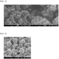
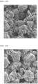
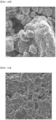
- the size of the primary particle was observed and measured using a SEM (model name: SEM, manufacturer: JEOL).
- FIG. 1 shows the measurement results of the particle size distribution of the porous carbon materials used in the Examples 1 to 3 and in Comparative Example 1.
- Example 4 The SEM images of the porous carbon materials used in Example 4 and Comparative Example 2 are shown in FIG. 2 and in FIG. 3 , respectively.
- a positive electrode for a lithium-sulfur battery was manufactured using the sulfur-carbon composites obtained in each of the Examples 1 to 4 and in Comparative Example 1 and Comparative Example 2 as described below.
- the prepared positive electrode slurry composition was coated on a 20 ⁇ m thick aluminum current collector to the thickness of 350 ⁇ m, dried at 50 °C for 12 hours, and rolled using a roll press to manufacture a positive electrode.
- the sulfur (S) content in the positive electrodes to which the sulfur-carbon composites of the Examples 1 to 3 and Comparative Example 1 were applied was 67.5 wt%
- the sulfur (S) content in the positive electrodes to which the sulfur-carbon composites of Example 4 and Comparative Example 2 were applied was 63.0 wt%.
- the areas of the sulfur-carbon composites were thereby measured through the number of pixels occupied by one sulfur-carbon composite on the SEM image, and the average was measured as an arithmetic mean value.
- FIG. 4 shows a top-view SEM image of the positive electrode manufactured using the sulfur-carbon composite of Comparative Example 1.
- FIG. 5 shows the top-view SEM images of the manufactured positive electrode using the sulfur-carbon composite of Example 1.
- Error % standard deviation / average ⁇ 100 [Table 3] Sulfur-carbon composite Error of the area of the sulfur-carbon composite in the positive electrode (%)
- Example 1 68.7 Example 2 70.4
- SEM images (model name: SEM, manufacturer: JEOL) of the vertical cross-section of the positive electrodes manufactured using the sulfur-carbon composites of example 2 and comparative example 2 were acquired, as shown in FIG 6A and FIG. 7A .
- one point on the surface of the current collector 1 was randomly selected in the cross-section SEM image of the positive electrode 2.
- a straight connection 3 perpendicular to the surface of the current collector was made between the point 1 and the surface 4 of the positive electrode 2 and the length of the straight connection 3 was determined.
- one point on the surface of the current collector was randomly selected in the obtained cross-section SEM image.
- a straight connection (line) perpendicular to the surface of the current collector is made between the randomly selected point and the surface of the positive electrode above this point.
- the length of the straight connection (line) (L) was measured as shown in FIG. 6B and FIG. 7B .
- the minimum distance 5 within the pore space between point 1 and the point where the straight connection 3 and the surface 4 meet was measured, that is, the minimum distance 5 it can be traveled along the surfaces of the particles forming the active layer of the positive electrode.
- Turtuosity value minimum distance 5 length of straight connection 3
- the average tortuosity value was determined by determining different tortuosity values at different locations A, B and C of the positive electrode 2 and calculating an average value thereof.
- SEM images (model name: SEM, manufacturer: JEOL) of the top view of the positive electrodes are acquired under the conditions specified herein in detail. Respective exemplary images are shown in FIG. 16A for example 1 and FIG 16B for comparative example 1 with a magnification of the SEM image of 400 times.
- the SEM images have a size of 200 ⁇ m X 200 ⁇ m.
- one point X 1 on the surface of the current collector is randomly selected in the top-view SEM image of the positive electrode.
- a line segment L X with a length of 200 ⁇ m from position X 1 to position X 2 is drawn on the top-view SEM image of the positive electrode.
- L X and L Y may form a cross as shown in FIGS. 16a and 16b .
- the shortest line between the positive electrode active material particles from X 1 to X 2 on the top-view SEM image of the positive electrode is measured to determine D X .
- the shortest line between the positive electrode active material particles from Y 1 to Y 2 on the top-view SEM image of the positive electrode is measured to determine D Y . Similar as described for the tortuosity value of cross-section evaluation of electrode as it is presented above.
- D X and D Y reflect the minimum distance along the surfaces of the particles forming the active layer of the positive electrode.
- the positive electrodes containing the sulfur-carbon composite obtained in each of Examples 1 to 4 and Comparative Example 1 and Comparative Example 2 were used for the manufacture of a positive electrode of a lithium-sulfur battery as described below.
- the positive electrode manufactured as described above and a negative electrode were placed with a separator interposed between the positive electrode and the negative electrode to form an electrode assembly.
- the electrode assembly was received in a pouch-type case and an electrolyte solution was filled to manufacture a lithium-sulfur battery.
- a 35 ⁇ m thick lithium metal foil was used for the negative electrode.
- a porous polyethylene separator having a thickness of 16 ⁇ m was used for the separator.
- the electrolyte was prepared by adding 3 wt% of LiNO 3 to an organic solvent mixture of 2-methyl furan and dimethoxyethanol (33/77 volume ratio) at the concentration of 1 M LiPF 6
- a pouch cell comprising the positive electrode and the negative electrode manufactured as described above.
- the El/S ratio in each manufactured battery was controlled to fulfill the requirement of 3.1 g/g.
- Each lithium-sulfur battery manufactured as described above was discharged at 0.5 C in CC mode at 25 °C until 1.8 V and charged with 0.3 C at a constant current until 2.5V, and then discharged at 1.0 C.
- the discharge capacity was measured based on the weight of sulfur (S). (mAh/g(S) (g(S) is the weight of sulfur)
- FIG. 8 is a graph showing the changes of the discharge capacity during repeated charging/discharging.
- FIG. 9 shows the relative capacity of the Examples 1 to 3 when the discharge capacity of the Comparative Example 1 is 1.
- FIG. 10 shows the relative nominal voltage of Examples 1 to 3 when the voltage of Comparative Example 1 is at 1.
- Table 5 shows the capacity measured at the initial discharge after charge.
- Sulfur (S) content in sulfur-carbon composites 1.0 C discharge capacity (mAh/g(S))
- Example 1 75 wt% 1,030
- Example 2 75 wt% 989
- Example 3 75 wt% 996 Comparative
- Example 1 75 wt% 976
- Example 4 70 wt% 1,035 Comparative Example 2 70 wt% 915
- Each lithium-sulfur battery manufactured as described above was discharged at 0.5 C in CC mode at 25 °C until 1.8 V and charged with 0.5 C constant current until 2.5 V, and the discharge capacity was measured/compared. The measurement results are shown in Table 6. The discharge capacity was measured based on the weight of sulfur. (mAh/g(S) (g(S) is the weight of sulfur))
- the energy density was measured according to Equation 3 below using the measured 0.5 C discharge capacity values.
- the relative values of the energy density of Example 1 based on the energy density of Comparative Example 1, and the energy density of Comparative Example 2 based on the energy density of Comparative Example 2 are shown in Table 6.
- Energy density discharge capacity ⁇ drive voltage / cell weight [Table 6] Sulfur (S) content in sulfur-carbon composites 0.5 C discharge capacity (mAh/g(S)) Energy density (relative value)
- Example 1 75 wt% 1,073 1.06
- Comparative Example 1 75 wt% 1,015 1.00
- FIG. 2 and FIG. 3 it was confirmed that the porous carbon material having a BF (D 90 /D 10 ) of 7 or less ( FIG. 2 ) had a uniform particle size compared to the porous carbon material having a large BF ( FIG. 3 ). It was also confirmed that the gap between the porous carbon materials was narrow.
- the lithium-sulfur battery according to an embodiment of the present invention achieved a large discharge capacity of 1,000 mAh/g(S) or more at a high discharge rate of 1.0 C.
- the amount of the active material in the positive electrode was the same, a higher energy density than Comparative Examples 1 and 2 was achieved.
- An SEM image of the upper surface of the positive electrode active material layer of the positive electrode manufactured using the sulfur-carbon composite of each of Example 1 and Comparative example 1 was obtained.
- the SEM images were obtained in 200 ⁇ m X 200 ⁇ m size at 400x magnification and in 70 ⁇ m X 70 ⁇ m size at 1,000x magnification based on the center of each of the obtained positive electrodes.
- the SEM image of 70 ⁇ mX70 ⁇ m size was obtained within the area of the obtained SEM images of 200 ⁇ mX200 ⁇ m size.
- the SEM image of 70 ⁇ mX70 ⁇ m size may be used for verification of particle sizes in the 200 ⁇ mX200 ⁇ m size SEM image.
- the lithium-sulfur battery was manufactured as follows.
- the lithium-sulfur battery was manufactured by placing the positive electrode manufactured using the sulfur-carbon composite of Comparative example 1 and a negative electrode with a separator interposed between the positive electrode and the negative electrode to make an electrode assembly, receiving the electrode assembly in a pouch type case and injecting an electrolyte solution.
- a 35 ⁇ m thick lithium metal foil was used for the negative electrode.
- a 16 ⁇ m thick porous polyethylene was used for the separator.
- the electrolyte solution was prepared by adding 3 wt% of LiNO 3 and 1M LiPF 6 to a mixed organic solvent of 2-methyl furan and dimethoxyethane (33/77 volume ratio).
- a pouch cell including the positive electrode and the negative electrode manufactured as described above was fabricated. In each battery, El/S was controlled to 3.1 g/g condition.
- Each lithium-sulfur battery manufactured as described above was discharged at 0.5C in a CC mode at 25°C up to 1.8 V and charged by a constant current of 0.3C up to 2.5 V, and discharging and charging was repeatedly performed at 1.0C for 200 cycles. In this instance, it was confirmed that the discharge capacity was maintained at 80% or more based on the initial capacity 100% using a charge and discharge tester.
- the lithium-sulfur battery at SOC 75% was disassembled in a glove box under an Ar atmosphere, and the positive electrode was separated.
- the surface of the separated positive electrode was washed using DME and dried, and whether or not Equation 2 is satisfied was evaluated by the same method as Evaluation example 1.
- FIGS. 15a and 15b shows the SEM image obtained as described above, and in FIG. 15a , the longest line segment of the five sulfur-carbon composite particles with the biggest surface in the SEM image is indicated, and in FIG. 15b , the longest line segments of the five sulfur-carbon composite particles with the smallest surface in the SEM image is indicated.
- Equation 2A The result of the calculation according to the following Equation 2A is shown in the following Table 9. [Table 9] (Evaluation after battery disassembly) X L /X S Whether or not Equation 2 is satisfied (True/Fail) Comparative example 1 23.2 Fail
Landscapes
- Chemical & Material Sciences (AREA)
- Chemical Kinetics & Catalysis (AREA)
- Electrochemistry (AREA)
- General Chemical & Material Sciences (AREA)
- Engineering & Computer Science (AREA)
- Materials Engineering (AREA)
- Inorganic Chemistry (AREA)
- Manufacturing & Machinery (AREA)
- Composite Materials (AREA)
- Battery Electrode And Active Subsutance (AREA)
Applications Claiming Priority (12)
| Application Number | Priority Date | Filing Date | Title |
|---|---|---|---|
| KR20220159965 | 2022-11-25 | ||
| KR20220183586 | 2022-12-23 | ||
| KR20220183771 | 2022-12-23 | ||
| KR20220185613 | 2022-12-27 | ||
| KR1020230063394A KR20240103938A (ko) | 2022-12-27 | 2023-05-16 | 황-탄소 복합체를 포함하는 양극 활물질 및 이를 포함하는 리튬-황 이차전지 |
| KR1020230070299A KR20240078583A (ko) | 2022-11-25 | 2023-05-31 | 다공성 탄소재의 입경 제어방법 |
| KR1020230073163A KR20240101314A (ko) | 2022-12-23 | 2023-06-07 | 다공성 탄소재 및 이를 포함하는 리튬황 전지와 그 제조방법 |
| KR1020230075765A KR20240101316A (ko) | 2022-12-23 | 2023-06-13 | 황-탄소 복합체를 포함하는 양극 활물질 및 이를 포함하는 리튬-황 이차 전지 |
| US202318244083A | 2023-09-08 | 2023-09-08 | |
| EP23196130 | 2023-09-08 | ||
| KR1020230119938A KR20240078311A (ko) | 2022-11-25 | 2023-09-08 | 황-탄소 복합체를 포함하는 양극 활물질 및 고출력 특성을 갖는 리튬-황 이차전지 |
| EP23212087.3A EP4376115B1 (de) | 2022-11-25 | 2023-11-24 | Positivelektrodenaktivmaterial mit schwefel-kohlenstoff-verbundstoff und lithium-schwefel-sekundärbatterie damit |
Related Parent Applications (2)
| Application Number | Title | Priority Date | Filing Date |
|---|---|---|---|
| EP23212087.3A Division-Into EP4376115B1 (de) | 2022-11-25 | 2023-11-24 | Positivelektrodenaktivmaterial mit schwefel-kohlenstoff-verbundstoff und lithium-schwefel-sekundärbatterie damit |
| EP23212087.3A Division EP4376115B1 (de) | 2022-11-25 | 2023-11-24 | Positivelektrodenaktivmaterial mit schwefel-kohlenstoff-verbundstoff und lithium-schwefel-sekundärbatterie damit |
Publications (2)
| Publication Number | Publication Date |
|---|---|
| EP4535482A2 true EP4535482A2 (de) | 2025-04-09 |
| EP4535482A3 EP4535482A3 (de) | 2025-06-11 |
Family
ID=88863416
Family Applications (2)
| Application Number | Title | Priority Date | Filing Date |
|---|---|---|---|
| EP25159869.4A Pending EP4535482A3 (de) | 2022-11-25 | 2023-11-24 | Positivelektrodenaktivmaterial mit schwefel-kohlenstoff-verbundstoff und lithium-schwefel-sekundärbatterie damit |
| EP23212087.3A Active EP4376115B1 (de) | 2022-11-25 | 2023-11-24 | Positivelektrodenaktivmaterial mit schwefel-kohlenstoff-verbundstoff und lithium-schwefel-sekundärbatterie damit |
Family Applications After (1)
| Application Number | Title | Priority Date | Filing Date |
|---|---|---|---|
| EP23212087.3A Active EP4376115B1 (de) | 2022-11-25 | 2023-11-24 | Positivelektrodenaktivmaterial mit schwefel-kohlenstoff-verbundstoff und lithium-schwefel-sekundärbatterie damit |
Country Status (1)
| Country | Link |
|---|---|
| EP (2) | EP4535482A3 (de) |
Family Cites Families (2)
| Publication number | Priority date | Publication date | Assignee | Title |
|---|---|---|---|---|
| KR102229453B1 (ko) * | 2017-11-24 | 2021-03-17 | 주식회사 엘지화학 | 황-탄소 복합체, 그의 제조방법 및 이를 포함하는 리튬 이차전지 |
| KR102639669B1 (ko) * | 2018-11-02 | 2024-02-21 | 주식회사 엘지에너지솔루션 | 황-탄소 복합체, 이의 제조방법 및 이를 이용한 리튬 이차 전지 |
-
2023
- 2023-11-24 EP EP25159869.4A patent/EP4535482A3/de active Pending
- 2023-11-24 EP EP23212087.3A patent/EP4376115B1/de active Active
Also Published As
| Publication number | Publication date |
|---|---|
| EP4376115B1 (de) | 2026-03-18 |
| EP4535482A3 (de) | 2025-06-11 |
| EP4376115A2 (de) | 2024-05-29 |
| EP4376115A3 (de) | 2024-08-28 |
Similar Documents
| Publication | Publication Date | Title |
|---|---|---|
| KR102229453B1 (ko) | 황-탄소 복합체, 그의 제조방법 및 이를 포함하는 리튬 이차전지 | |
| EP3096379A1 (de) | Negativelektrodenaktivmaterial für wasserfreie sekundärbatterien und verfahren zur herstellung von negativelektrodenaktivmaterialpartikeln | |
| US11539043B2 (en) | Negative active material, lithium battery including the negative active material, and method of preparing the negative active material | |
| US9219278B2 (en) | Non-aqueous electrolyte secondary battery and use thereof | |
| EP4394923A1 (de) | Negativelektrodenaktivmaterial und herstellungsverfahren dafür, sekundärbatterie mit negativelektrodenaktivmaterial und elektrische vorrichtung | |
| EP4261949A1 (de) | Kathode mit schwefel-kohlenstoff-verbundstoffen und lithium-ionen-sekundärbatterie damit | |
| EP4261939B1 (de) | Positivelektrodenaktivmaterial für lithiumsekundärbatterie, verfahren zur herstellung davon und lithiumsekundärbatterie damit | |
| EP4276944B1 (de) | Positive elektrode, die einen schwefel-kohlenstoff-verbundwerkstoff aufweist, und lithium-ionen-sekundärbatterie die diese enthält | |
| EP4376115B1 (de) | Positivelektrodenaktivmaterial mit schwefel-kohlenstoff-verbundstoff und lithium-schwefel-sekundärbatterie damit | |
| US12191483B2 (en) | Positive electrode active material comprising sulfur-carbon composite and lithium-sulfur secondary battery comprising the same | |
| KR20230140539A (ko) | 이종의 도전재를 포함하는 리튬-황 전지용 양극 및 이를 포함하는 리튬 이온 이차 전지 | |
| KR102775172B1 (ko) | 황-탄소 복합체를 포함하는 양극 활물질 및 고출력 특성을 갖는 리튬-황 이차전지 | |
| KR102848337B1 (ko) | 리튬 황 전지용 전극 및 이를 포함하는 고에너지밀도의 리튬 황 전지 | |
| US20240178388A1 (en) | Positive electrode and lithium-sulfur battery comprising the same | |
| EP4261948B1 (de) | Positivelektrode mit schwefel-kohlenstoff-verbundstoff und lithium-ionen-sekundärbatterie damit | |
| KR20250027694A (ko) | 황-탄소 복합체를 포함하는 양극 활물질 및 고출력 특성을 갖는 리튬-황 이차전지 | |
| CN118511326A (zh) | 包含硫碳复合体的正极活性材料和具有高功率特性的锂硫二次电池 | |
| KR20240103938A (ko) | 황-탄소 복합체를 포함하는 양극 활물질 및 이를 포함하는 리튬-황 이차전지 | |
| CA3286726A1 (en) | Electrode for lithium sulfur battery and lithium sulfur battery including the same | |
| KR20240101316A (ko) | 황-탄소 복합체를 포함하는 양극 활물질 및 이를 포함하는 리튬-황 이차 전지 | |
| JP2025523807A (ja) | リチウム-硫黄電池用正極及び高エネルギー密度特性を有するリチウム-硫黄電池 | |
| JP6634318B2 (ja) | 非水電解質電池用活物質、非水電解質電池用電極、非水電解質電池および電池パック | |
| KR20230062451A (ko) | 황-탄소 복합체를 포함하는 양극 및 이를 포함하는 리튬 이온 이차 전지 | |
| CA3244480A1 (en) | POSITIVE ELECTRODE FOR SECONDARY LITHIUM BATTERY AND METHOD FOR ITS MANUFACTURE | |
| CN118402092A (zh) | 锂硫电池用正极和具有高能量密度的锂硫电池 |
Legal Events
| Date | Code | Title | Description |
|---|---|---|---|
| PUAI | Public reference made under article 153(3) epc to a published international application that has entered the european phase |
Free format text: ORIGINAL CODE: 0009012 |
|
| STAA | Information on the status of an ep patent application or granted ep patent |
Free format text: STATUS: REQUEST FOR EXAMINATION WAS MADE |
|
| 17P | Request for examination filed |
Effective date: 20250225 |
|
| AC | Divisional application: reference to earlier application |
Ref document number: 4376115 Country of ref document: EP Kind code of ref document: P |
|
| AK | Designated contracting states |
Kind code of ref document: A2 Designated state(s): AL AT BE BG CH CY CZ DE DK EE ES FI FR GB GR HR HU IE IS IT LI LT LU LV MC ME MK MT NL NO PL PT RO RS SE SI SK SM TR |
|
| REG | Reference to a national code |
Ref country code: DE Ref legal event code: R079 Free format text: PREVIOUS MAIN CLASS: H01M0010052000 Ipc: H01M0004130000 |
|
| PUAL | Search report despatched |
Free format text: ORIGINAL CODE: 0009013 |
|
| AK | Designated contracting states |
Kind code of ref document: A3 Designated state(s): AL AT BE BG CH CY CZ DE DK EE ES FI FR GB GR HR HU IE IS IT LI LT LU LV MC ME MK MT NL NO PL PT RO RS SE SI SK SM TR |
|
| RIC1 | Information provided on ipc code assigned before grant |
Ipc: H01M 4/62 20060101ALI20250506BHEP Ipc: H01M 4/02 20060101ALI20250506BHEP Ipc: H01M 4/1397 20100101ALI20250506BHEP Ipc: H01M 4/136 20100101ALI20250506BHEP Ipc: H01M 4/133 20100101ALI20250506BHEP Ipc: H01M 10/052 20100101ALI20250506BHEP Ipc: H01M 4/583 20100101ALI20250506BHEP Ipc: H01M 4/58 20100101ALI20250506BHEP Ipc: H01M 4/38 20060101ALI20250506BHEP Ipc: H01M 4/36 20060101ALI20250506BHEP Ipc: H01M 4/139 20100101ALI20250506BHEP Ipc: H01M 4/13 20100101AFI20250506BHEP |