EP4535480A1 - Lithiumsekundärbatterie und verbundelement - Google Patents
Lithiumsekundärbatterie und verbundelement Download PDFInfo
- Publication number
- EP4535480A1 EP4535480A1 EP23815980.0A EP23815980A EP4535480A1 EP 4535480 A1 EP4535480 A1 EP 4535480A1 EP 23815980 A EP23815980 A EP 23815980A EP 4535480 A1 EP4535480 A1 EP 4535480A1
- Authority
- EP
- European Patent Office
- Prior art keywords
- spacer
- negative electrode
- separator
- positive electrode
- lithium
- Prior art date
- Legal status (The legal status is an assumption and is not a legal conclusion. Google has not performed a legal analysis and makes no representation as to the accuracy of the status listed.)
- Pending
Links
Images






Classifications
-
- H—ELECTRICITY
- H01—ELECTRIC ELEMENTS
- H01M—PROCESSES OR MEANS, e.g. BATTERIES, FOR THE DIRECT CONVERSION OF CHEMICAL ENERGY INTO ELECTRICAL ENERGY
- H01M50/00—Constructional details or processes of manufacture of the non-active parts of electrochemical cells other than fuel cells, e.g. hybrid cells
- H01M50/40—Separators; Membranes; Diaphragms; Spacing elements inside cells
- H01M50/471—Spacing elements inside cells other than separators, membranes or diaphragms; Manufacturing processes thereof
- H01M50/477—Spacing elements inside cells other than separators, membranes or diaphragms; Manufacturing processes thereof characterised by their shape
-
- H—ELECTRICITY
- H01—ELECTRIC ELEMENTS
- H01M—PROCESSES OR MEANS, e.g. BATTERIES, FOR THE DIRECT CONVERSION OF CHEMICAL ENERGY INTO ELECTRICAL ENERGY
- H01M10/00—Secondary cells; Manufacture thereof
- H01M10/05—Accumulators with non-aqueous electrolyte
- H01M10/052—Li-accumulators
-
- H—ELECTRICITY
- H01—ELECTRIC ELEMENTS
- H01M—PROCESSES OR MEANS, e.g. BATTERIES, FOR THE DIRECT CONVERSION OF CHEMICAL ENERGY INTO ELECTRICAL ENERGY
- H01M4/00—Electrodes
- H01M4/02—Electrodes composed of, or comprising, active material
- H01M4/36—Selection of substances as active materials, active masses, active liquids
- H01M4/38—Selection of substances as active materials, active masses, active liquids of elements or alloys
- H01M4/381—Alkaline or alkaline earth metals elements
- H01M4/382—Lithium
-
- H—ELECTRICITY
- H01—ELECTRIC ELEMENTS
- H01M—PROCESSES OR MEANS, e.g. BATTERIES, FOR THE DIRECT CONVERSION OF CHEMICAL ENERGY INTO ELECTRICAL ENERGY
- H01M50/00—Constructional details or processes of manufacture of the non-active parts of electrochemical cells other than fuel cells, e.g. hybrid cells
- H01M50/40—Separators; Membranes; Diaphragms; Spacing elements inside cells
- H01M50/471—Spacing elements inside cells other than separators, membranes or diaphragms; Manufacturing processes thereof
- H01M50/474—Spacing elements inside cells other than separators, membranes or diaphragms; Manufacturing processes thereof characterised by their position inside the cells
-
- H—ELECTRICITY
- H01—ELECTRIC ELEMENTS
- H01M—PROCESSES OR MEANS, e.g. BATTERIES, FOR THE DIRECT CONVERSION OF CHEMICAL ENERGY INTO ELECTRICAL ENERGY
- H01M50/00—Constructional details or processes of manufacture of the non-active parts of electrochemical cells other than fuel cells, e.g. hybrid cells
- H01M50/10—Primary casings; Jackets or wrappings
- H01M50/102—Primary casings; Jackets or wrappings characterised by their shape or physical structure
- H01M50/107—Primary casings; Jackets or wrappings characterised by their shape or physical structure having curved cross-section, e.g. round or elliptic
-
- Y—GENERAL TAGGING OF NEW TECHNOLOGICAL DEVELOPMENTS; GENERAL TAGGING OF CROSS-SECTIONAL TECHNOLOGIES SPANNING OVER SEVERAL SECTIONS OF THE IPC; TECHNICAL SUBJECTS COVERED BY FORMER USPC CROSS-REFERENCE ART COLLECTIONS [XRACs] AND DIGESTS
- Y02—TECHNOLOGIES OR APPLICATIONS FOR MITIGATION OR ADAPTATION AGAINST CLIMATE CHANGE
- Y02E—REDUCTION OF GREENHOUSE GAS [GHG] EMISSIONS, RELATED TO ENERGY GENERATION, TRANSMISSION OR DISTRIBUTION
- Y02E60/00—Enabling technologies; Technologies with a potential or indirect contribution to GHG emissions mitigation
- Y02E60/10—Energy storage using batteries
Definitions
- Patent Literature 1 discloses a lithium secondary battery including: a positive electrode that contains a lithium-containing positive electrode active material; a negative electrode that is provided to face the positive electrode, and includes a negative electrode current collector; a separator provided between the positive electrode and the negative electrode; and a lithium ion-conductive non-aqueous electrolyte, wherein the negative electrode current collector includes: a layer having a first surface and a second surface that is opposite to the first surface; a plurality of first protrusions that protrude from the first surface; and a plurality of second protrusions that protrude from the second surface, wherein lithium metal deposits on the first surface and the second surface during charge, and a total area of portions where the plurality of first protrusions and the plurality of second protrusions overlap each other when viewed from the normal direction of the first surface is 1/2 or less of a total area of the plurality of first protrusions.
- the lower limits and the upper limits shown below can be combined in any way as long as the lower limits are not greater than or equal to the upper limits.
- only one material may be selected from among the plurality of materials and used, or a combination of two or more may be selected from among the plurality of materials and used.
- FIG. 2 is a cross-sectional view schematically showing a main part of an electrode group included in an example of a lithium secondary battery according to an embodiment of the present disclosure.
- FIG. 2(a) and FIG. 2(b) show the main part of the electrode group during discharge and during charge, respectively.
- FIG. 2 shows, in the case where the electrode group is a stack-type electrode group, a cross section taken in the stack direction, and in the case where the electrode group is a wound-type electrode group, a cross section taken in the winding axis direction.
- the electrode group includes a positive electrode 11, a negative electrode 12 and a separator 13.
- a first spacer 51 is provided between the negative electrode 12 and the separator 13, and a second spacer 52 is provided between the positive electrode 11 and the separator 13.
- a first space 51s is formed on a surface of the negative electrode 12 (the surface being the surface that faces the positive electrode 11) by the first spacer 51.
- a second space 52s is formed on a surface of the positive electrode 11 (the surface being the surface that faces the negative electrode 12) by the second spacer 52.
- the lithium secondary battery according to the present disclosure by providing the first spacer and the second spacer, it is possible to suppress the depletion of the non-aqueous electrolyte in the electrode group while suppressing the expansion of the electrode group during repetition of charge and discharge. As a result, the cycle characteristics (discharge capacity retention rate) of the lithium secondary battery can be enhanced.
- a second spacer 52 is provided without providing a first spacer
- a second space 52s is formed on the surface of the positive electrode 11, but a first space is not formed on the surface of the negative electrode 12.
- the second spacer 52 is pushed toward the positive electrode 11 together with the separator 13 by the deposited lithium metal 12a during charge. As a result, the distance between the negative electrode 12 and the positive electrode 11 increases, which may cause the electrode group to expand.
- a ratio T1/T2 of a thickness T1 of the first spacer relative to a thickness T2 of the second spacer may be 1/3 or more, and is preferably 1 or more, and more preferably 2 or more. From the viewpoint that depletion of the non-aqueous electrolyte in the electrode group is likely to be suppressed, the ratio T1/T2 may be 7 or less, and is preferably 5 or less, and more preferably 3 or less.
- the thickness T1 of the first spacer is, for example, 10 ⁇ m or more and 35 ⁇ m or less.
- the term "the thickness of a spacer" is synonymous with the height of protrusions that constitute the spacer.
- the thickness of the first spacer can be reduced as compared with the case where only the first spacer is used. Accordingly, the separator can be provided near the negative electrode, and it is therefore possible to prevent lithium metal from sparsely depositing. That is, the deposition form of lithium metal can be controlled, and formation of dendrites (isolation of lithium metal, short circuiting, and the like caused by the formation of dendrites) can be suppressed.
- a ratio S1/S0 of an area S1 in contact with the first spacer in a region on one surface of the negative electrode that faces the positive electrode relative to an area S0 of the region on the one surface of the negative electrode that faces the positive electrode may be 0.2 or less or 0.15 or less.
- the ratio S1/S0 may be 0.03 or more or 0.05 or more.
- a ratio S2/S0 of an area S2 in contact with the second spacer in a region on one surface of the positive electrode that faces the negative electrode relative to an area S0 of the region on the one surface of the positive electrode that faces the negative electrode may be 0.2 or less or 0.15 or less.
- the ratio S2/S0 may be 0.03 or more or 0.05 or more.
- Each spacer is composed of, for example, a plurality of protrusions.
- the protrusions may have a line shape, a dot shape, or the like.
- the line shape may be linear or curved.
- the spacer may be composed of a plurality of line-shaped protrusions, or may be composed of a plurality of dot-shaped protrusions provided in a distributed manner. Adjacent line-shaped protrusions may be connected to each other or spaced apart from each other.
- the line-shaped protrusions may have a width of 100 ⁇ m or more (or 200 ⁇ m or more) and 2000 ⁇ m or less (or 1000 ⁇ m or less).
- a resin material may be used as the insulating material.
- the resin material include a polyolefin resin, an acrylic resin, a polyamide resin, a polyimide resin, a silicone resin, a fluorine-based resin, a urethane resin, a melamine resin, a urea resin, and the like.
- a cured product of a curable resin such as an epoxy resin may also be used.
- a less lithium ion permeable resin material such as a polyimide, polyvinylidene fluoride, or an acrylonitrile-acrylic acid ester copolymer may also be used in the spacer.
- the sealing member 16 includes a filter 22, a lower valve 23, an insulating member 24, an upper valve 25, and a cap 26. These members are stacked in this order in the sealing member 16.
- the sealing member 16 is attached to the opening of the case main body 15 such that the cap 26 is positioned outside of the case main body 15 and the filter 22 is positioned inside of the case main body 15.
- the above-described members that constitute the sealing member 16 have, for example, a disc or ring shape.
- the lower valve 23 and the upper valve 25 are connected to each other at their center portions, with the insulating member 24 being interposed between their peripheral edges.
- the filter 22 and the lower valve 23 are connected to each other at their center portions.
- the upper valve 25 and the cap 26 are connected to each other at their center portions. That is, the members excluding the insulating member 24 are electrically connected to each other.
- the electrode group 14 includes a positive electrode 11, a negative electrode 12, and a separator 13.
- the positive electrode 11, the negative electrode 12, and the separator 13 all have a strip shape.
- the positive electrode 11 and the negative electrode 12 are spirally wound with the separator 13 interposed therebetween such that the width direction of the strip-shaped positive electrode 11 and the strip-shaped negative electrode 12 is parallel to the winding axis.
- the positive electrode 11 and the negative electrode 12 are alternately layered in the radial direction of the electrode group 14 with the separator 13 being interposed therebetween. That is, the lengthwise direction of the electrodes corresponds to the winding direction, and the width direction of the electrodes corresponds to the axis direction.
- the positive electrode 11 includes a positive electrode current collector and a positive electrode material mixture layers supported on both surfaces of the positive electrode current collector.
- the positive electrode current collector of the positive electrode 11 is electrically connected to the cap 26 that functions as a positive electrode terminal via a positive electrode lead 19.
- a negative electrode a negative electrode current collector on which lithium metal deposition has not occurred is shown.
- the negative electrode 12 is electrically connected to the case main body 15 that functions as a negative electrode terminal via a negative electrode lead 20.
- the lithium secondary battery according to the present disclosure will be described specifically based on examples and comparative examples. However, it is to be noted that the present disclosure is not limited to the examples given below.
- the obtained positive electrode material mixture slurry was applied to both surfaces of a strip-shaped Al foil (as a positive electrode current collector), and dried to form positive electrode material mixture coating films on the both surfaces of the strip-shaped Al foil.
- the coating films were rolled using a roller.
- the obtained stacked body of the positive electrode current collector and the positive electrode material mixture was cut into a predetermined electrode size. In this way, a positive electrode including positive electrode material mixture layers on both surfaces of the positive electrode current collector was produced.
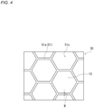
- the mesh shape of the first spacer was regular hexagonal.
- the height of line-shaped protrusions constituting the first spacer was set to 30 ⁇ m (the first spacer having a thickness T1 of 30 ⁇ m).
- the spacing between every two opposite sides of a regular hexagonal mesh shape was set to about 4.5 mm.
- the width of the line-shaped protrusions was set to 0.25 mm.
- an area S1 of the first spacer was set to 10% of an area S0 of the facing region.
- Batteries A2 to A4 were produced in the same manner as the battery A1 of Example 1 was produced, except that the thickness T1 of the first spacer and the thickness T2 of the second spacers were changed to values shown in Table 1.
- the above-described charge/discharge process was defined as one cycle, and each produced battery was charged for two cycles. Then, a battery before being subjected to the charge/discharge process and the battery charged for two cycles were each disassembled to take out the stacked body including: the positive electrode with the second spacers provided on both surfaces thereof; the negative electrode; and the two separators provided on both surfaces of the negative electrode (the two separators being the first separator and the second separator each with the spacer provided on their negative electrode-side surface).
- the disassembling of the batteries was performed in an inert gas atmosphere.
- the stacked bodies taken out of the batteries were cleaned with dimethyl carbonate and then dried.
- a thickness Xd of the stacked body of the battery before being subjected to the charge/discharge process was determined.
- the thickness Xd of the stacked body of the battery before being subj ected to the charge/discharge process is a total thickness of the constituent members of the stacked body of the battery before being subjected to the charge/discharge process. That is, the thickness Xd is a total thickness of the positive electrode, the negative electrode, the two separators, the first spacers provided on the negative electrode-side surface of each of the two separators, and the second spacers provided on one surface and the other surface of the positive electrode.
- Electrode group expansion rate Xc / Xd ⁇ 100
- Table 1 Battery First spacer Second spacer Thickness ratio T1/T2 Initial charge capacity (mAh) Electrode group expansion rate (%) Discharge capacity retention rate at 200th cycle (%) Thickness T1 ( ⁇ m) Pattern Thickness T2 ( ⁇ m) Pattern A2 35 Honeycomb 5 Honeycomb 7 488 103.4 85 A1 30 Honeycomb 10 Honeycomb 3 488 103.4 91 A3 20 Honeycomb 20 Honeycomb 1 488 104.4 90 A4 10 Honeycomb 30 Honeycomb 1/3 488 105.8 85 A5 30 Honeycomb 10 Stripe 3 488 103.7 92 B1 40 Honeycomb 0 - - 491 103.4 82 B2 0 - 40 Honeycomb - 496 110.2 83
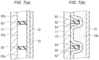
- the electrode group expansion rate was reduced, but because the second spacers were not provided, the non-aqueous electrolyte contained in the electrode group depleted, resulting in a low discharge capacity retention rate.
- the electrode group expansion rate was high, and the discharge capacity retention rate was low.
- the batteries B1 and B2 included the electrode groups as shown in FIGS. 6 and 7 , respectively.
- the lithium secondary battery according to the present disclosure is applicable to: electronic devices including mobile phones, smartphones, and tablet terminals; electric vehicles including hybrid vehicles and plug-in hybrid vehicles; home storage batteries combined with solar cells; and the like.
Landscapes
- Chemical & Material Sciences (AREA)
- Chemical Kinetics & Catalysis (AREA)
- Electrochemistry (AREA)
- General Chemical & Material Sciences (AREA)
- Engineering & Computer Science (AREA)
- Manufacturing & Machinery (AREA)
- Materials Engineering (AREA)
- Secondary Cells (AREA)
Applications Claiming Priority (2)
| Application Number | Priority Date | Filing Date | Title |
|---|---|---|---|
| JP2022088860 | 2022-05-31 | ||
| PCT/JP2023/019780 WO2023234223A1 (ja) | 2022-05-31 | 2023-05-26 | リチウム二次電池および複合部材 |
Publications (2)
| Publication Number | Publication Date |
|---|---|
| EP4535480A1 true EP4535480A1 (de) | 2025-04-09 |
| EP4535480A4 EP4535480A4 (de) | 2025-12-10 |
Family
ID=89024986
Family Applications (1)
| Application Number | Title | Priority Date | Filing Date |
|---|---|---|---|
| EP23815980.0A Pending EP4535480A4 (de) | 2022-05-31 | 2023-05-26 | Lithiumsekundärbatterie und verbundelement |
Country Status (5)
| Country | Link |
|---|---|
| US (1) | US20250349980A1 (de) |
| EP (1) | EP4535480A4 (de) |
| JP (1) | JPWO2023234223A1 (de) |
| CN (1) | CN119174023A (de) |
| WO (1) | WO2023234223A1 (de) |
Families Citing this family (1)
| Publication number | Priority date | Publication date | Assignee | Title |
|---|---|---|---|---|
| WO2026071102A1 (ja) * | 2024-09-30 | 2026-04-02 | パナソニックIpマネジメント株式会社 | リチウム二次電池 |
Family Cites Families (4)
| Publication number | Priority date | Publication date | Assignee | Title |
|---|---|---|---|---|
| US20150188185A1 (en) * | 2013-12-31 | 2015-07-02 | Microsoft Corporation | Reinforcement of battery |
| JP7194940B2 (ja) | 2018-05-31 | 2022-12-23 | パナソニックIpマネジメント株式会社 | リチウム二次電池 |
| CN112673504B (zh) * | 2018-09-28 | 2024-03-01 | 松下知识产权经营株式会社 | 锂二次电池 |
| JP7813987B2 (ja) * | 2020-08-31 | 2026-02-16 | パナソニックIpマネジメント株式会社 | リチウム二次電池 |
-
2023
- 2023-05-26 EP EP23815980.0A patent/EP4535480A4/de active Pending
- 2023-05-26 WO PCT/JP2023/019780 patent/WO2023234223A1/ja not_active Ceased
- 2023-05-26 US US18/869,651 patent/US20250349980A1/en active Pending
- 2023-05-26 CN CN202380039740.3A patent/CN119174023A/zh active Pending
- 2023-05-26 JP JP2024524830A patent/JPWO2023234223A1/ja active Pending
Also Published As
| Publication number | Publication date |
|---|---|
| JPWO2023234223A1 (de) | 2023-12-07 |
| EP4535480A4 (de) | 2025-12-10 |
| US20250349980A1 (en) | 2025-11-13 |
| WO2023234223A1 (ja) | 2023-12-07 |
| CN119174023A (zh) | 2024-12-20 |
Similar Documents
| Publication | Publication Date | Title |
|---|---|---|
| EP3576198B1 (de) | Lithiumsekundärbatterie | |
| EP3576197B1 (de) | Lithiumsekundärbatterie | |
| JP7209256B2 (ja) | リチウム二次電池 | |
| EP4300623A1 (de) | Lithiumsekundärbatterie | |
| EP3537522B1 (de) | Lithiumsekundärbatterie mit lithium-ionen-leitendem wasserfreiem elektrolyten | |
| US11271250B2 (en) | Lithium ion secondary battery | |
| EP3422457B1 (de) | Lithiumsekundärbatterie | |
| EP3537523B1 (de) | Lithiumsekundärbatterie mit lithium-ionen-leitendem wasserfreiem elektrolyten | |
| EP3584875A1 (de) | Lithiumsekundärbatterie | |
| EP4379942A1 (de) | Lithiumsekundärbatterie | |
| EP3576183B1 (de) | Lithiumsekundärbatterie | |
| JP7209257B2 (ja) | リチウム二次電池 | |
| EP4535480A1 (de) | Lithiumsekundärbatterie und verbundelement | |
| JP6927306B2 (ja) | リチウムイオン二次電池 | |
| EP4503244A1 (de) | Sekundärbatterie | |
| JP7162175B2 (ja) | リチウム二次電池 | |
| EP4675741A1 (de) | Lithiumsekundärbatterie | |
| EP4645510A1 (de) | Lithiumsekundärbatterie und separator | |
| EP4645511A1 (de) | Lithiumsekundärbatterie und separator | |
| CN121909545A (zh) | 二次电池 | |
| WO2026071195A1 (ja) | 二次電池およびセパレータ |
Legal Events
| Date | Code | Title | Description |
|---|---|---|---|
| STAA | Information on the status of an ep patent application or granted ep patent |
Free format text: STATUS: THE INTERNATIONAL PUBLICATION HAS BEEN MADE |
|
| PUAI | Public reference made under article 153(3) epc to a published international application that has entered the european phase |
Free format text: ORIGINAL CODE: 0009012 |
|
| STAA | Information on the status of an ep patent application or granted ep patent |
Free format text: STATUS: REQUEST FOR EXAMINATION WAS MADE |
|
| 17P | Request for examination filed |
Effective date: 20241224 |
|
| AK | Designated contracting states |
Kind code of ref document: A1 Designated state(s): AL AT BE BG CH CY CZ DE DK EE ES FI FR GB GR HR HU IE IS IT LI LT LU LV MC ME MK MT NL NO PL PT RO RS SE SI SK SM TR |
|
| DAV | Request for validation of the european patent (deleted) | ||
| DAX | Request for extension of the european patent (deleted) | ||
| A4 | Supplementary search report drawn up and despatched |
Effective date: 20251106 |
|
| RIC1 | Information provided on ipc code assigned before grant |
Ipc: H01M 10/052 20100101AFI20251031BHEP Ipc: H01M 4/134 20100101ALI20251031BHEP Ipc: H01M 10/0568 20100101ALI20251031BHEP Ipc: H01M 10/058 20100101ALI20251031BHEP Ipc: H01M 50/451 20210101ALI20251031BHEP Ipc: H01M 50/457 20210101ALI20251031BHEP Ipc: H01M 50/46 20210101ALI20251031BHEP Ipc: H01M 50/463 20210101ALI20251031BHEP Ipc: H01M 50/489 20210101ALI20251031BHEP |