EP4535355A1 - Kontaktbetriebsvorrichtung und tonsignalwiedergabeverfahren - Google Patents
Kontaktbetriebsvorrichtung und tonsignalwiedergabeverfahren Download PDFInfo
- Publication number
- EP4535355A1 EP4535355A1 EP23815636.8A EP23815636A EP4535355A1 EP 4535355 A1 EP4535355 A1 EP 4535355A1 EP 23815636 A EP23815636 A EP 23815636A EP 4535355 A1 EP4535355 A1 EP 4535355A1
- Authority
- EP
- European Patent Office
- Prior art keywords
- contact operation
- operation portion
- arm
- playback
- sound signal
- Prior art date
- Legal status (The legal status is an assumption and is not a legal conclusion. Google has not performed a legal analysis and makes no representation as to the accuracy of the status listed.)
- Pending
Links
Images




Classifications
-
- G—PHYSICS
- G06—COMPUTING OR CALCULATING; COUNTING
- G06F—ELECTRIC DIGITAL DATA PROCESSING
- G06F3/00—Input arrangements for transferring data to be processed into a form capable of being handled by the computer; Output arrangements for transferring data from processing unit to output unit, e.g. interface arrangements
- G06F3/01—Input arrangements or combined input and output arrangements for interaction between user and computer
- G06F3/048—Interaction techniques based on graphical user interfaces [GUI]
- G06F3/0484—Interaction techniques based on graphical user interfaces [GUI] for the control of specific functions or operations, e.g. selecting or manipulating an object, an image or a displayed text element, setting a parameter value or selecting a range
- G06F3/04847—Interaction techniques to control parameter settings, e.g. interaction with sliders or dials
-
- G—PHYSICS
- G06—COMPUTING OR CALCULATING; COUNTING
- G06F—ELECTRIC DIGITAL DATA PROCESSING
- G06F3/00—Input arrangements for transferring data to be processed into a form capable of being handled by the computer; Output arrangements for transferring data from processing unit to output unit, e.g. interface arrangements
- G06F3/01—Input arrangements or combined input and output arrangements for interaction between user and computer
- G06F3/03—Arrangements for converting the position or the displacement of a member into a coded form
- G06F3/033—Pointing devices displaced or positioned by the user, e.g. mice, trackballs, pens or joysticks; Accessories therefor
- G06F3/039—Accessories therefor, e.g. mouse pads
- G06F3/0393—Accessories for touch pads or touch screens, e.g. mechanical guides added to touch screens for drawing straight lines, hard keys overlaying touch screens or touch pads
-
- G—PHYSICS
- G06—COMPUTING OR CALCULATING; COUNTING
- G06F—ELECTRIC DIGITAL DATA PROCESSING
- G06F3/00—Input arrangements for transferring data to be processed into a form capable of being handled by the computer; Output arrangements for transferring data from processing unit to output unit, e.g. interface arrangements
- G06F3/01—Input arrangements or combined input and output arrangements for interaction between user and computer
- G06F3/048—Interaction techniques based on graphical user interfaces [GUI]
- G06F3/0487—Interaction techniques based on graphical user interfaces [GUI] using specific features provided by the input device, e.g. functions controlled by the rotation of a mouse with dual sensing arrangements, or of the nature of the input device, e.g. tap gestures based on pressure sensed by a digitiser
- G06F3/0488—Interaction techniques based on graphical user interfaces [GUI] using specific features provided by the input device, e.g. functions controlled by the rotation of a mouse with dual sensing arrangements, or of the nature of the input device, e.g. tap gestures based on pressure sensed by a digitiser using a touch-screen or digitiser, e.g. input of commands through traced gestures
-
- G—PHYSICS
- G06—COMPUTING OR CALCULATING; COUNTING
- G06F—ELECTRIC DIGITAL DATA PROCESSING
- G06F3/00—Input arrangements for transferring data to be processed into a form capable of being handled by the computer; Output arrangements for transferring data from processing unit to output unit, e.g. interface arrangements
- G06F3/01—Input arrangements or combined input and output arrangements for interaction between user and computer
- G06F3/048—Interaction techniques based on graphical user interfaces [GUI]
- G06F3/0487—Interaction techniques based on graphical user interfaces [GUI] using specific features provided by the input device, e.g. functions controlled by the rotation of a mouse with dual sensing arrangements, or of the nature of the input device, e.g. tap gestures based on pressure sensed by a digitiser
- G06F3/0488—Interaction techniques based on graphical user interfaces [GUI] using specific features provided by the input device, e.g. functions controlled by the rotation of a mouse with dual sensing arrangements, or of the nature of the input device, e.g. tap gestures based on pressure sensed by a digitiser using a touch-screen or digitiser, e.g. input of commands through traced gestures
- G06F3/04883—Interaction techniques based on graphical user interfaces [GUI] using specific features provided by the input device, e.g. functions controlled by the rotation of a mouse with dual sensing arrangements, or of the nature of the input device, e.g. tap gestures based on pressure sensed by a digitiser using a touch-screen or digitiser, e.g. input of commands through traced gestures for inputting data by handwriting, e.g. gesture or text
-
- G—PHYSICS
- G06—COMPUTING OR CALCULATING; COUNTING
- G06F—ELECTRIC DIGITAL DATA PROCESSING
- G06F3/00—Input arrangements for transferring data to be processed into a form capable of being handled by the computer; Output arrangements for transferring data from processing unit to output unit, e.g. interface arrangements
- G06F3/01—Input arrangements or combined input and output arrangements for interaction between user and computer
- G06F3/048—Interaction techniques based on graphical user interfaces [GUI]
- G06F3/0487—Interaction techniques based on graphical user interfaces [GUI] using specific features provided by the input device, e.g. functions controlled by the rotation of a mouse with dual sensing arrangements, or of the nature of the input device, e.g. tap gestures based on pressure sensed by a digitiser
- G06F3/0488—Interaction techniques based on graphical user interfaces [GUI] using specific features provided by the input device, e.g. functions controlled by the rotation of a mouse with dual sensing arrangements, or of the nature of the input device, e.g. tap gestures based on pressure sensed by a digitiser using a touch-screen or digitiser, e.g. input of commands through traced gestures
- G06F3/04886—Interaction techniques based on graphical user interfaces [GUI] using specific features provided by the input device, e.g. functions controlled by the rotation of a mouse with dual sensing arrangements, or of the nature of the input device, e.g. tap gestures based on pressure sensed by a digitiser using a touch-screen or digitiser, e.g. input of commands through traced gestures by partitioning the display area of the touch-screen or the surface of the digitising tablet into independently controllable areas, e.g. virtual keyboards or menus
-
- G—PHYSICS
- G06—COMPUTING OR CALCULATING; COUNTING
- G06F—ELECTRIC DIGITAL DATA PROCESSING
- G06F3/00—Input arrangements for transferring data to be processed into a form capable of being handled by the computer; Output arrangements for transferring data from processing unit to output unit, e.g. interface arrangements
- G06F3/16—Sound input; Sound output
- G06F3/165—Management of the audio stream, e.g. setting of volume, audio stream path
-
- G—PHYSICS
- G11—INFORMATION STORAGE
- G11B—INFORMATION STORAGE BASED ON RELATIVE MOVEMENT BETWEEN RECORD CARRIER AND TRANSDUCER
- G11B27/00—Editing; Indexing; Addressing; Timing or synchronising; Monitoring; Measuring tape travel
- G11B27/10—Indexing; Addressing; Timing or synchronising; Measuring tape travel
- G11B27/102—Programmed access in sequence to addressed parts of tracks of operating record carriers
-
- G—PHYSICS
- G11—INFORMATION STORAGE
- G11B—INFORMATION STORAGE BASED ON RELATIVE MOVEMENT BETWEEN RECORD CARRIER AND TRANSDUCER
- G11B27/00—Editing; Indexing; Addressing; Timing or synchronising; Monitoring; Measuring tape travel
- G11B27/10—Indexing; Addressing; Timing or synchronising; Measuring tape travel
- G11B27/34—Indicating arrangements
-
- G—PHYSICS
- G11—INFORMATION STORAGE
- G11B—INFORMATION STORAGE BASED ON RELATIVE MOVEMENT BETWEEN RECORD CARRIER AND TRANSDUCER
- G11B3/00—Recording by mechanical cutting, deforming or pressing, e.g. of grooves or pits; Reproducing by mechanical sensing; Record carriers therefor
- G11B3/02—Arrangements of heads
- G11B3/10—Arranging, supporting, or driving of heads or of transducers relatively to record carriers
- G11B3/12—Supporting in balanced, counterbalanced or loaded operative position during transducing, e.g. loading in direction of traverse
-
- G—PHYSICS
- G11—INFORMATION STORAGE
- G11B—INFORMATION STORAGE BASED ON RELATIVE MOVEMENT BETWEEN RECORD CARRIER AND TRANSDUCER
- G11B3/00—Recording by mechanical cutting, deforming or pressing, e.g. of grooves or pits; Reproducing by mechanical sensing; Record carriers therefor
- G11B3/02—Arrangements of heads
- G11B3/10—Arranging, supporting, or driving of heads or of transducers relatively to record carriers
- G11B3/34—Driving or guiding during transducing operation
- G11B3/38—Guiding, e.g. constructions or arrangements providing linear or other special tracking characteristics
-
- H—ELECTRICITY
- H04—ELECTRIC COMMUNICATION TECHNIQUE
- H04M—TELEPHONIC COMMUNICATION
- H04M1/00—Substation equipment, e.g. for use by subscribers
- H04M1/02—Constructional features of telephone sets
- H04M1/04—Supports for telephone transmitters or receivers
-
- H—ELECTRICITY
- H04—ELECTRIC COMMUNICATION TECHNIQUE
- H04M—TELEPHONIC COMMUNICATION
- H04M1/00—Substation equipment, e.g. for use by subscribers
- H04M1/72—Mobile telephones; Cordless telephones, i.e. devices for establishing wireless links to base stations without route selection
- H04M1/724—User interfaces specially adapted for cordless or mobile telephones
- H04M1/72403—User interfaces specially adapted for cordless or mobile telephones with means for local support of applications that increase the functionality
- H04M1/72409—User interfaces specially adapted for cordless or mobile telephones with means for local support of applications that increase the functionality by interfacing with external accessories
- H04M1/72412—User interfaces specially adapted for cordless or mobile telephones with means for local support of applications that increase the functionality by interfacing with external accessories using two-way short-range wireless interfaces
-
- H—ELECTRICITY
- H04—ELECTRIC COMMUNICATION TECHNIQUE
- H04M—TELEPHONIC COMMUNICATION
- H04M1/00—Substation equipment, e.g. for use by subscribers
- H04M1/72—Mobile telephones; Cordless telephones, i.e. devices for establishing wireless links to base stations without route selection
- H04M1/724—User interfaces specially adapted for cordless or mobile telephones
- H04M1/72403—User interfaces specially adapted for cordless or mobile telephones with means for local support of applications that increase the functionality
- H04M1/72442—User interfaces specially adapted for cordless or mobile telephones with means for local support of applications that increase the functionality for playing music files
Definitions
- the present invention relates to a contact operation device and a sound signal playback method using a contact operation device.
- a portable information terminal having a function of playing songs, such as smartphones, is known.
- a portable information terminal disclosed in Patent Literature 1 information necessary to select a music piece is provided to a user using a touchscreen.
- Patent Literature 1 JP5048768B
- a portable information terminal such as a smartphone starts playback of sound signals, in response to an operation of touching a touchscreen with a finger or a stylus pen.
- Such an operation is simple and convenient for users but does not impress users.
- record players still have strong popularity.
- a user moves a pickup at a tip end of an arm of the record player and brings a record needle provided on the pickup into contact with a record groove of a vinyl record. Upon the record needle contacting the record groove, the sound is emitted.
- the emotional movement of tension and relaxation at the moment the sound is emitted impresses many users.
- a contact operation device includes: an arm including a contact operation portion at a tip end thereof, the contact operation portion being configured to contact a touchscreen; and a support part configured to support the arm, the support part including a first support mechanism configured to allow the arm to move such that the contact operation portion is carried in a horizontal direction, and a second support mechanism configured to allow the arm to move such that the contact operation portion is carried in a vertical direction.
- a sound signal playback method is a playback method for playing back a sound signal by a contact operation device and a portable information terminal, in which: the portable information terminal includes a touchscreen; the contact operation device includes: an arm including a contact operation portion at a tip end thereof, the contact operation portion being configured to contact the touchscreen; and a support part configured to support the arm, the support part including a first support mechanism configured to allow the arm to move such that the contact operation portion is carried in a horizontal direction, and a second support mechanism configured to allow the arm to move such that the contact operation portion is carried in a vertical direction; and the portable information terminal is configured to: display, on the touchscreen, an image of a recording medium on which a sound signal is recorded; determine, in a case in which the contact operation portion contacts the touchscreen displaying the image of the recording medium, a playback start position of the sound signal based on a contact position of the contact operation portion in the image of the recording medium; and start playback of the sound signal from the playback start position.
- a sound signal playback method is a playback method for playing back a sound signal by a contact operation device and a portable information terminal, in which: the portable information terminal includes a touchscreen; the contact operation device includes: an arm including a contact operation portion at a tip end thereof, the contact operation portion being configured to contact the touchscreen; a support part configured to support the arm, the support part including a first support mechanism configured to allow the arm to move such that the contact operation portion is carried in a horizontal direction, and a second support mechanism configured to allow the arm to move such that the contact operation portion is carried in a vertical direction; a communication unit configured to receive a drive command from the portable information terminal; and a drive unit configured to move the contact operation portion by driving the arm in response to the drive command; and the portable information terminal is configured to: display, on the touchscreen an image of a recording medium on which the sound signal is recorded, in response to receiving a selection of a sound signal; and transmit, to the contact operation device, a drive command to cause the contact operation portion
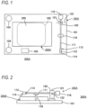
- FIG. 1 is a plan view showing a configuration of a playback system 300A that executes a sound signal playback method according to a first embodiment of the present invention.
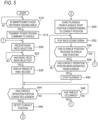
- FIG. 2 is a side view showing the configuration of the playback system 300A.
- the playback system 300A includes a smartphone 200A including a touchscreen 205 and a cradle 100A having a function of performing wireless power feeding to the smartphone 200A.
- the cradle 100A is a contact operation device that performs a contact operation on the touchscreen 205 of the smartphone 200A and has a shape similar to a record player.
- the smartphone 200A is a portable information terminal that plays back a sound signal in response to a contact operation performed by the cradle 100A.
- the cradle 100A includes a base 101 in the shape of a rectangular flat plate.
- a substantially rectangular power feeding area 102 is provided at an approximate center of the base 101, and a primary coil (not shown) is embedded in the power feeding area 102.
- a user places the smartphone 200A, which is a power feeding target, on the power feeding area 102.
- the cradle 100A generates an AC magnetic field by flowing an AC current through the primary coil and performs wireless power feeding to the smartphone 200A placed on the power feeding area 102.
- a short-range wireless communication unit 103 is arranged near one of long sides of the base 101.
- the short-range wireless communication unit 103 is, for example, a Bluetooth (registered trademark) communication unit and is a means for performing short-range wireless communication with the smartphone 200A as a communication partner.
- the cradle 100A receives a sound signal played back by the smartphone 200A via the short-range wireless communication unit 103.
- Two sound output units 104 are provided near both ends of one short side of the base 101.
- the sound output units 104 are speakers.
- the cradle 100A emits sound signals received by the short-range wireless communication unit 103 from the sound output units 104.
- An arm 111 supported by a support part 120 is arranged near the other short side of the base 101.
- a pickup 112 is attached to a tip end of the arm 111.
- a counterweight 116 is attached to a rear end of the arm 111.
- the support part 120 supports a position, close to the counterweight 116, in the arm 111.
- the support part 120 supports the arm 111 so as to be pivotable around a first axis 121 in a vertical direction and to be pivotable around a second axis 122 in a horizontal direction.
- the counterweight 116 serves to reduce a pivoting speed of the arm 111 when the arm pivots around the second axis 122 due to its own weight.
- the base 101 is provided with a rest part 118 that supports a middle portion of the arm 111 between the support part 120 and the pickup 112 from below.
- the arm 111 is placed on the rest part 118.
- a contact operation portion 114 is attached to a lower portion of the pickup 112 at the tip end of the arm 111.
- the contact operation portion 114 is a member configured to contact the touchscreen 205 of the smartphone 200A placed on the power feeding area 102, and is made of a conductive elastomer.
- the pickup 112 is provided with a handle 113. The user can pick up the handle 113 with a finger and move the pickup 112.
- the arm 111 to which the pickup 112 is attached can pivot around the first axis 121. Accordingly, the contact operation portion 114 of the pickup 112 can move in an arc with a radius corresponding to a distance from the contact operation portion 114 to the first axis 121.
- the circular orbit passes through a center of the touchscreen 205 of the smartphone 200A.
- the first axis 121 functions as a first support mechanism configured to allow the arm 111 to move such that the contact operation portion 114 is carried in the horizontal direction.
- the arm 111 to which the pickup 112 is attached can pivot around the second axis 122. Accordingly, the contact operation portion 114 of the pickup 112 can contact the touchscreen 205 of the smartphone 200A by descending, or can be separated from the touchscreen 205 by ascending. In this way, the second axis 122 functions as a second support mechanism configured to allow the arm 111 to move such that the contact operation portion 114 is carried in the vertical direction.
- the cradle 100A functions as a contact operation device configured to cause the contact operation portion 114 to contact a desired position on the touchscreen 205 of the smartphone 200A, or cause the contact operation portion 114 to be separated from the touchscreen 205.
- the moment of inertia acting on a tip end portion of the arm 111 is greater than the moment of inertia acting on a rear end portion of the arm 111. Accordingly, when the user brings the contact operation portion 114 into contact with the touchscreen 205 and then detaches the finger from the handle 113, the contact operation portion 114 continues to remain in contact with the touchscreen 205.
- FIG. 3 is a block diagram showing an electrical configuration of the cradle 100A.
- the cradle 100A includes a CPU 131, a storage unit 132, a short-range wireless communication unit 103, a wireless power feeding unit 133, and a sound output unit 104.
- the CPU 131 is a control means for controlling each unit of the cradle 100A.
- the short-range wireless communication unit 103 and the sound output unit 104 are as described with reference to FIGS. 1 and 2 .
- the wireless power feeding unit 133 includes a primary coil embedded in the power feeding area 102.
- the wireless power feeding unit 133 generates an AC magnetic field for power feeding to the smartphone 200A by flowing an AC current through the primary coil.
- the storage unit 132 is configured by a nonvolatile storage such as a ROM and a flash memory, and a volatile storage such as a RAM.
- a control program that is executed by the CPU 131 is stored.
- the volatile storage is used as a work area by the CPU 131.
- the CPU 131 executes the control program in the nonvolatile storage, thereby controlling power feeding by the wireless power feeding unit 133 and controlling operations of receiving a sound signal from the smartphone 200A by the short-range wireless communication unit 103 and emitting a sound by the sound output unit 104.
- FIG. 4 is a block diagram showing an electrical configuration of the smartphone 200A.
- the smartphone 200A includes a CPU 201, a storage unit 202, a sound input unit 203, a sound output unit 204, a wireless communication unit 206, a short-range wireless communication unit 207, a wireless charging unit 208, and a battery 209.
- the sound input unit 203 is a microphone, and the sound output unit 204 is a speaker.
- the sound input unit 203 and the sound output unit 204 are mainly used as a means for calls.
- the touchscreen 205 is a device that has both a display function of displaying various pieces of information and an operation function of receiving a contact operation. In the present embodiment, the touchscreen 205 becomes an operation target of the contact operation portion 114 of the cradle 100A.
- the wireless communication unit 206 is a means for communicating with other communication devices via a network including a mobile communication network and the Internet.
- the battery 209 is a DC power source that supplies power to each unit in the smartphone 200A.
- the wireless charging unit 208 receives power from the wireless power feeding unit 133 of the cradle 100A and charges the battery 209. More specifically, the wireless charging unit 208 includes a secondary coil, which is magnetically coupled to the primary coil in the wireless power feeding unit 133, and charges the battery 209 by rectifying an AC current generated in the secondary coil and flowing
- the storage unit 202 is configured by a nonvolatile storage such as a ROM and a flash memory, and a volatile storage such as a RAM.
- a nonvolatile storage such as a ROM and a flash memory
- a volatile storage such as a RAM.
- the volatile storage is used as a work area by the CPU 201.
- the CPU 201 controls each unit in the smartphone 200A by executing the control program in the non-volatile memory.
- one or more sound signal files in which sound signals of various music pieces are time-sequenced are stored.
- a playback application program that reads out a sound signal from a sound signal file and causes the CPU 201 to execute playback processing for playing back the sound signal as a sound is stored.
- the sound signal file and the playback application program are downloaded from, for example, a server connected to the Internet and stored in the nonvolatile storage of the storage unit 202.
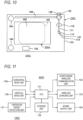
- FIG. 5 is a flow chart showing playback processing that is executed by the CPU 201 according to the playback application program.
- the CPU 201 starts the playback processing shown in FIG. 5 .
- the CPU 201 determines whether the smartphone 200A is placed on the power feeding area 102 of the cradle 100A (step S10). This determination can be made by, for example, comparing a peak level of an AC voltage generated in the secondary coil in the wireless charging unit 208 with a threshold value. If the determination result in step S10 is "NO”, the CPU 201 repeats the determination in step S10. If the determination result in step S10 is "YES", the processing of the CPU 201 proceeds to step S12.
- the CPU 201 transmits a power feeding command to the cradle 100A via the short-range wireless communication unit 207.
- the CPU 131 of the cradle 100A receives the power feeding command via the short-range wireless communication unit 103, the CPU 131 increases the current flowing through the primary coil of the wireless power feeding unit 133, thereby increasing the AC power supplied to the wireless charging unit 208 of the smartphone 200A. This initiates wireless charging of the smartphone 200A by the cradle 100A.
- step S20 when proceeding to step S20, the CPU 201 displays a menu for receiving a music piece selection on the touchscreen 205.
- step S22 the CPU 201 determines whether a music piece has been selected. If the determination result is "NO”, the CPU 201 repeats the determination in step S22. If the determination result in step S22 is "YES”, the processing of the CPU 201 proceeds to step S30.
- the CPU 201 displays an image of a vinyl record corresponding to a sound signal file of the music piece selected by the user on the touchscreen 205.
- the sound signal which is played back by the CPU 201, is stored in the sound signal file in the storage unit 202.
- the present embodiment is to give the user an operating feel similar to that of a record player. Therefore, the CPU 201, in step S30, displays, as an image of a recording medium on which a sound signal is recorded, an image of a vinyl record on the touchscreen 205.
- the image of the recording medium may be in the shape of a donut, imitating the shape of a vinyl record.
- FIG. 6 is a plan view illustrating a state in which an image of a vinyl record 400 is displayed on the touchscreen 205.
- the image of the vinyl record 400 includes each image of a center Q of the vinyl record 400, an outermost record groove Cst of the vinyl record 400, and an innermost record groove Cen of the vinyl record 400.
- a distance between the outermost record groove Cst and the innermost record groove Cen in the radial direction of the vinyl record 400 corresponds to a total time length of the sound signal stored in the sound signal file.
- step S44 the CPU 201 determines whether the contact operation unit 114 has made contact with a screen of the touchscreen 205. If the determination result is "NO”, the processing of the CPU 201 proceeds to step S48, and if the determination result is "YES”, the processing of the CPU 201 proceeds to step S46.
- step S48 the CPU 201 determines whether a timeout has occurred, i.e., whether the state in which the determination result in step S44 is "NO" has continued for a predetermined time. If the determination result is "NO”, the processing of the CPU 201 returns to step S44, and if the determination result is "YES", the processing of the CPU 201 returns to step S20.
- step S44 determines whether the determination result in step S44 is "YES" and the CPU 201 proceeds to step S46.
- the CPU 201 detects a contact position of the contact operation portion 114 on the touchscreen 205.
- the CPU 201 starts playback of the sound signal from a playback start position corresponding to the contact position.
- step S50 the processing in step S50 is described with reference to FIG. 7 .
- the distance L1 between the outermost record groove Cst and the innermost record groove Cen in the radial direction of the vinyl record 400 corresponds to the total time length T of the sound signal stored in the sound signal file. Therefore, the CPU 201 obtains a radial distance L2 from the record groove to which the contact position P belongs to the outermost record groove Cst in the image of the vinyl record 400 displayed on the touchscreen 205. Then, the CPU 201 sets a position advanced by L2 ⁇ T/L1 from the beginning of the sound signal in the sound signal file, as the playback start position.
- the CPU 201 plays back a sound signal of a predetermined amount of time, starting from the current playback position in the sound signal in the sound signal file, and transmits it to the cradle 100A via the short-range wireless communication unit 207.
- the sound signal is received by the short-range wireless communication unit 103 of the cradle 100 and emitted by the sound output unit 104.
- the playback position on the time axis advances by a predetermined amount of time.
- the CPU 201 determines whether the playback position has reached a playback end position.
- the playback end position refers to the last position in the sound signal in the sound signal file. If the determination result is "NO”, the processing of the CPU 201 proceeds to step S58, and if the determination result is "YES”, the CPU 201 performs playback stop processing (not shown) and returns to step S20.
- step S52 the playback of the sound signal (step S52) is repeated during the time from when the contact operation portion 114 comes into contact with the screen of the touchscreen 205 until the playback position reaches the playback end position, or until the contact operation portion 114 is separated from the screen of the touchscreen 205.
- step S60 when proceeding to step S60, the CPU 201 stops the playback of the sound signal in the sound signal file. Then, the processing of the CPU 201 returns to step S44.
- step S48 it is assumed that the user separates the contact operation portion 114 from the screen of the touchscreen 205, and brings the contact operation portion 114 into contact with the screen of the touchscreen 205 before a timeout occurs in step S48.
- the processing of the CPU 201 proceeds to step S44 via step S60.
- the determination result in step S44 becomes "YES”
- the CPU 201 detects the contact position of the contact operation portion 114 on the touchscreen 205 (step S46).
- step S50 sets the position corresponding to the contact position as the playback start position
- step S56 when the playback position reaches the playback end position, the determination result in step S56 becomes "YES", and the CPU 201 performs playback stop processing (not shown) and returns to the reception of music piece selection (step S20).
- the smartphone 200A serving as a portable information terminal includes the touchscreen 205
- the cradle 100A serving as a contact operation device includes: the arm 111 including the contact operation portion 114 at the tip end thereof, the contact operation portion 114 being configured to contact the touchscreen 205; and the support part 120 configured to support the arm 111 and including the first axis 121 serving as a first support mechanism configured to allow the arm 111 to move such that the contact operation portion 114 is carried in the horizontal direction, and the second axis 122 serving as a second support mechanism configured to allow the arm 111 to move such that the contact operation portion 114 is carried in the vertical direction.
- the smartphone 200A is configured to: display, on the touchscreen 205, the image of the vinyl record 400 serving as a recording medium on which a sound signal is recorded; determine, in a case in which the contact operation portion 114 contacts the touchscreen 205 displaying the image of the vinyl record 400, a playback start position of the sound signal based on a contact position of the contact operation portion 114 in the image displayed on the touchscreen 205; and start playback of the sound signal from the playback start position. Therefore, according to the present embodiment, it is possible to give the user an operating feel similar to that of a record player.
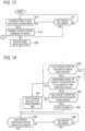
- the playback system 300C includes a smartphone 200A having the same configuration as that shown in the first embodiment.
- the smartphone 200A in the present embodiment has a function of causing the contact position of the contact operation portion 114 on the touchscreen 205 to follow the playback position, and a function of lifting the contact operation portion 114 from the touchscreen 205 and moving the arm 111 to the rest part 118 when playback of a sound signal in the sound signal file ends.
- the smartphone 200A in the present embodiment further has two additional functions.
- a first additional function is a function of initiating playback of a sound signal in response to an operation on the touchscreen 205, and moving the contact operation portion 114 to a position corresponding to the playback start position and bringing it into contact.
- a second additional function is a function of stopping playback of a sound signal in response to an operation on the touchscreen 205 and moving the arm 111 to the rest part 118.
- FIG. 12 is a flow chart of playback processing that is executed by the CPU 201 of the smartphone 200A according to the playback application program in the present embodiment.
- step S20 is replaced with step S20a
- steps S44, S46 and S48 are replaced with step S40
- step S58 is replaced with step S58a.
- the smartphone 200A is configured to: display, on the touch screen 205, an image of a vinyl record on which the sound signal is recorded, in response to receiving a selection of a sound signal; and transmit, to the cradle 100C, a drive command to the cradle to cause the contact operation portion 114 to contact a position on the screen of the touchscreen 205, the position corresponding to the playback start position of the sound signal. Accordingly, the contact operation unit 114 contacts a position on the screen of the touchscreen 205 corresponding to the playback start position, and playback of the sound signal starts. Therefore, the convenience of the playback system 300C can be improved.
Landscapes
- Engineering & Computer Science (AREA)
- Theoretical Computer Science (AREA)
- General Engineering & Computer Science (AREA)
- Human Computer Interaction (AREA)
- Physics & Mathematics (AREA)
- General Physics & Mathematics (AREA)
- Multimedia (AREA)
- Computer Networks & Wireless Communication (AREA)
- Signal Processing (AREA)
- Health & Medical Sciences (AREA)
- Audiology, Speech & Language Pathology (AREA)
- General Health & Medical Sciences (AREA)
- Position Input By Displaying (AREA)
- Management Or Editing Of Information On Record Carriers (AREA)
- Telephone Function (AREA)
Applications Claiming Priority (2)
| Application Number | Priority Date | Filing Date | Title |
|---|---|---|---|
| JP2022088391A JP7856939B2 (ja) | 2022-05-31 | 2022-05-31 | 音信号の再生システムおよび再生方法 |
| PCT/JP2023/016318 WO2023233875A1 (ja) | 2022-05-31 | 2023-04-25 | 接触操作装置および音信号の再生方法 |
Publications (2)
| Publication Number | Publication Date |
|---|---|
| EP4535355A1 true EP4535355A1 (de) | 2025-04-09 |
| EP4535355A4 EP4535355A4 (de) | 2026-05-20 |
Family
ID=89026259
Family Applications (1)
| Application Number | Title | Priority Date | Filing Date |
|---|---|---|---|
| EP23815636.8A Pending EP4535355A4 (de) | 2022-05-31 | 2023-04-25 | Kontaktbetriebsvorrichtung und tonsignalwiedergabeverfahren |
Country Status (5)
| Country | Link |
|---|---|
| US (1) | US20250094121A1 (de) |
| EP (1) | EP4535355A4 (de) |
| JP (1) | JP7856939B2 (de) |
| CN (1) | CN119256360A (de) |
| WO (1) | WO2023233875A1 (de) |
Family Cites Families (5)
| Publication number | Priority date | Publication date | Assignee | Title |
|---|---|---|---|---|
| JPS5452204U (de) * | 1977-09-20 | 1979-04-11 | ||
| US7730414B2 (en) | 2006-06-30 | 2010-06-01 | Sony Ericsson Mobile Communications Ab | Graphical display |
| JP2014032596A (ja) | 2012-08-06 | 2014-02-20 | Fujitsu Ltd | 試験装置、試験治具、及び試験方法 |
| JP2020050199A (ja) | 2018-09-27 | 2020-04-02 | 豊田合成株式会社 | 車両用ユーザーインタフェースシステム |
| JP7400220B2 (ja) | 2019-06-07 | 2023-12-19 | ヤマハ株式会社 | Av機器 |
-
2022
- 2022-05-31 JP JP2022088391A patent/JP7856939B2/ja active Active
-
2023
- 2023-04-25 CN CN202380042154.4A patent/CN119256360A/zh active Pending
- 2023-04-25 EP EP23815636.8A patent/EP4535355A4/de active Pending
- 2023-04-25 WO PCT/JP2023/016318 patent/WO2023233875A1/ja not_active Ceased
-
2024
- 2024-11-27 US US18/962,348 patent/US20250094121A1/en active Pending
Also Published As
| Publication number | Publication date |
|---|---|
| CN119256360A (zh) | 2025-01-03 |
| EP4535355A4 (de) | 2026-05-20 |
| WO2023233875A1 (ja) | 2023-12-07 |
| JP7856939B2 (ja) | 2026-05-12 |
| JP2023176224A (ja) | 2023-12-13 |
| US20250094121A1 (en) | 2025-03-20 |
Similar Documents
| Publication | Publication Date | Title |
|---|---|---|
| JP6265401B2 (ja) | メディアを再生するための方法および端末 | |
| US9253267B2 (en) | Portable electronic apparatus functioning as pen-table and computer system using the same | |
| EP1956601A2 (de) | Verfahren und Endgerät zum Wiedergeben und Anzeigen von Musik | |
| US11150745B2 (en) | Media device | |
| US20050168566A1 (en) | Image processing device image processing program and image processing method | |
| CN111176515B (zh) | 显示设备及控制显示设备的方法 | |
| JP2006094414A (ja) | リモートコントロール方法、無線端末およびオーディオ再生装置 | |
| WO2016177296A1 (zh) | 一种生成视频的方法和装置 | |
| CN103716454A (zh) | 利用语音识别执行预设操作模式的方法和设备 | |
| US20110029867A1 (en) | Music reproducing apparatus and method of portable terminal | |
| WO2008018918A1 (en) | Mobile radio terminal with headset assembly having multi-function user input button and method | |
| KR20140097902A (ko) | 햅틱 패턴을 생성하는 휴대 단말 및 방법 | |
| JP6717940B2 (ja) | オーディオファイルの再録音方法、装置及び記憶媒体 | |
| JP2014228750A (ja) | 演奏記録システム、演奏記録方法および楽器 | |
| US12085981B2 (en) | Display device and operation method thereof | |
| US20250094121A1 (en) | Contact operation device and sound signal playback method | |
| JP5950546B2 (ja) | 携帯電子機器、方法及びプログラム | |
| KR101194539B1 (ko) | 미디어 파일 빠른 검색 방법 및 장치 | |
| JP2018530286A (ja) | 一体化された着脱式フェーダコンポーネントを備えるdj装置 | |
| JP2005520232A (ja) | 空間における装置の配置を記録するための手段を持つポータブルな電子装置 | |
| JP2015122645A (ja) | 制御装置、電子機器、制御システム、および制御方法 | |
| JP2015052653A (ja) | 音波形データ処理装置 | |
| KR102244293B1 (ko) | 모바일 기기와 연동되는 디지털 피아노 시스템 | |
| US9020914B2 (en) | Automatic song selection | |
| US20060187336A1 (en) | System, method and computer program product for distributed moderation of theatrical productions |
Legal Events
| Date | Code | Title | Description |
|---|---|---|---|
| STAA | Information on the status of an ep patent application or granted ep patent |
Free format text: STATUS: THE INTERNATIONAL PUBLICATION HAS BEEN MADE |
|
| PUAI | Public reference made under article 153(3) epc to a published international application that has entered the european phase |
Free format text: ORIGINAL CODE: 0009012 |
|
| STAA | Information on the status of an ep patent application or granted ep patent |
Free format text: STATUS: REQUEST FOR EXAMINATION WAS MADE |
|
| 17P | Request for examination filed |
Effective date: 20241129 |
|
| AK | Designated contracting states |
Kind code of ref document: A1 Designated state(s): AL AT BE BG CH CY CZ DE DK EE ES FI FR GB GR HR HU IE IS IT LI LT LU LV MC ME MK MT NL NO PL PT RO RS SE SI SK SM TR |
|
| DAV | Request for validation of the european patent (deleted) | ||
| DAX | Request for extension of the european patent (deleted) |