EP4535151A1 - Elektronische vorrichtung mit anzeige mit berührungsschaltung zur verarbeitung des kontakts eines externen objekts - Google Patents
Elektronische vorrichtung mit anzeige mit berührungsschaltung zur verarbeitung des kontakts eines externen objekts Download PDFInfo
- Publication number
- EP4535151A1 EP4535151A1 EP23839780.6A EP23839780A EP4535151A1 EP 4535151 A1 EP4535151 A1 EP 4535151A1 EP 23839780 A EP23839780 A EP 23839780A EP 4535151 A1 EP4535151 A1 EP 4535151A1
- Authority
- EP
- European Patent Office
- Prior art keywords
- data
- nodes
- processor
- electronic device
- control circuitry
- Prior art date
- Legal status (The legal status is an assumption and is not a legal conclusion. Google has not performed a legal analysis and makes no representation as to the accuracy of the status listed.)
- Pending
Links
Images


Classifications
-
- G—PHYSICS
- G06—COMPUTING OR CALCULATING; COUNTING
- G06F—ELECTRIC DIGITAL DATA PROCESSING
- G06F3/00—Input arrangements for transferring data to be processed into a form capable of being handled by the computer; Output arrangements for transferring data from processing unit to output unit, e.g. interface arrangements
- G06F3/01—Input arrangements or combined input and output arrangements for interaction between user and computer
- G06F3/03—Arrangements for converting the position or the displacement of a member into a coded form
- G06F3/041—Digitisers, e.g. for touch screens or touch pads, characterised by the transducing means
- G06F3/0412—Digitisers structurally integrated in a display
-
- G—PHYSICS
- G06—COMPUTING OR CALCULATING; COUNTING
- G06F—ELECTRIC DIGITAL DATA PROCESSING
- G06F3/00—Input arrangements for transferring data to be processed into a form capable of being handled by the computer; Output arrangements for transferring data from processing unit to output unit, e.g. interface arrangements
- G06F3/01—Input arrangements or combined input and output arrangements for interaction between user and computer
- G06F3/03—Arrangements for converting the position or the displacement of a member into a coded form
- G06F3/041—Digitisers, e.g. for touch screens or touch pads, characterised by the transducing means
- G06F3/0416—Control or interface arrangements specially adapted for digitisers
- G06F3/0418—Control or interface arrangements specially adapted for digitisers for error correction or compensation, e.g. based on parallax, calibration or alignment
- G06F3/04186—Touch location disambiguation
-
- G—PHYSICS
- G06—COMPUTING OR CALCULATING; COUNTING
- G06F—ELECTRIC DIGITAL DATA PROCESSING
- G06F3/00—Input arrangements for transferring data to be processed into a form capable of being handled by the computer; Output arrangements for transferring data from processing unit to output unit, e.g. interface arrangements
- G06F3/01—Input arrangements or combined input and output arrangements for interaction between user and computer
- G06F3/03—Arrangements for converting the position or the displacement of a member into a coded form
- G06F3/033—Pointing devices displaced or positioned by the user, e.g. mice, trackballs, pens or joysticks; Accessories therefor
- G06F3/0354—Pointing devices displaced or positioned by the user, e.g. mice, trackballs, pens or joysticks; Accessories therefor with detection of two-dimensional [2D] relative movements between the device, or an operating part thereof, and a plane or surface, e.g. 2D mice, trackballs, pens or pucks
- G06F3/03545—Pens or stylus
-
- G—PHYSICS
- G06—COMPUTING OR CALCULATING; COUNTING
- G06F—ELECTRIC DIGITAL DATA PROCESSING
- G06F3/00—Input arrangements for transferring data to be processed into a form capable of being handled by the computer; Output arrangements for transferring data from processing unit to output unit, e.g. interface arrangements
- G06F3/01—Input arrangements or combined input and output arrangements for interaction between user and computer
- G06F3/03—Arrangements for converting the position or the displacement of a member into a coded form
- G06F3/033—Pointing devices displaced or positioned by the user, e.g. mice, trackballs, pens or joysticks; Accessories therefor
- G06F3/038—Control and interface arrangements therefor, e.g. drivers or device-embedded control circuitry
-
- G—PHYSICS
- G06—COMPUTING OR CALCULATING; COUNTING
- G06F—ELECTRIC DIGITAL DATA PROCESSING
- G06F3/00—Input arrangements for transferring data to be processed into a form capable of being handled by the computer; Output arrangements for transferring data from processing unit to output unit, e.g. interface arrangements
- G06F3/01—Input arrangements or combined input and output arrangements for interaction between user and computer
- G06F3/03—Arrangements for converting the position or the displacement of a member into a coded form
- G06F3/041—Digitisers, e.g. for touch screens or touch pads, characterised by the transducing means
- G06F3/0414—Digitisers, e.g. for touch screens or touch pads, characterised by the transducing means using force sensing means to determine a position
- G06F3/04146—Digitisers, e.g. for touch screens or touch pads, characterised by the transducing means using force sensing means to determine a position using pressure sensitive conductive elements delivering a boolean signal and located between crossing sensing lines, e.g. located between X and Y sensing line layers
-
- G—PHYSICS
- G06—COMPUTING OR CALCULATING; COUNTING
- G06F—ELECTRIC DIGITAL DATA PROCESSING
- G06F3/00—Input arrangements for transferring data to be processed into a form capable of being handled by the computer; Output arrangements for transferring data from processing unit to output unit, e.g. interface arrangements
- G06F3/01—Input arrangements or combined input and output arrangements for interaction between user and computer
- G06F3/03—Arrangements for converting the position or the displacement of a member into a coded form
- G06F3/041—Digitisers, e.g. for touch screens or touch pads, characterised by the transducing means
- G06F3/0416—Control or interface arrangements specially adapted for digitisers
- G06F3/04166—Details of scanning methods, e.g. sampling time, grouping of sub areas or time sharing with display driving
Definitions
- the following descriptions relate to an electronic device including a display including touch circuitry processing contact of an external object.
- the electronic device may comprise a display panel including an area capable of receiving a touch input.
- the electronic device may comprise touch circuitry including control circuitry, and a touch sensor, the touch sensor including a plurality of nodes in the area.
- the electronic device may comprise a processor.
- the control circuitry may be configured to, based at least in part on an external object at least partially contacted on the area, respectively obtain a plurality of values via each of the plurality of nodes.
- the control circuitry may be configured to, based on the plurality of values, obtain first data indicating a partial area in the area that includes a representative location of the contact of the external object.
- the control circuitry may be configured to, based on the plurality of the values, obtain second data indicating at least a portion of the plurality of the nodes obtaining values within a reference range according to the contact of the external object.
- the control circuitry may be configured to, based at least in part on the second data, provide, to the processor, the first data, for recognizing the contact of the external object as a touch input on the area, or refrain from providing, to the processor, the first data.
- the electronic device may comprise a display panel including an area capable of receiving a touch input.
- the electronic device may comprise touch circuitry including control circuitry, and a touch sensor, the touch sensor including a plurality of nodes in the area.
- the electronic device may comprise a processor.
- the control circuitry may be configured to, based at least in part on an external object at least partially contacted on the area, respectively obtain a plurality of values via each of the plurality of nodes.
- the control circuitry may be configured to, based on the plurality of values, obtain first data indicating a partial area in the area that includes a representative location of the contact of the external object.
- the control circuitry may be configured to, based on the plurality of the values, obtain second data indicating at least a portion of the plurality of the nodes obtaining values within a reference range according to the contact of the external object.
- the control circuitry may be configured to provide, to the processor, the first data and the second data.
- the processor may be configured to, based at least in part on the second data, identify whether recognizing the first data as a touch input on the area.
- the electronic device 101 in the network environment 100 may communicate with an electronic device 102 via a first network 198 (e.g., a short-range wireless communication network), or at least one of an electronic device 104 or a server 108 via a second network 199 (e.g., a long-range wireless communication network).
- a first network 198 e.g., a short-range wireless communication network
- a second network 199 e.g., a long-range wireless communication network
- the electronic device 101 may communicate with the electronic device 104 via the server 108.
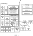
- the electronic device 101 may include a processor 120, memory 130, an input module 150, a sound output module 155, a display module 160, an audio module 170, a sensor module 176, an interface 177, a connecting terminal 178, a haptic module 179, a camera module 180, a power management module 188, a battery 189, a communication module 190, a subscriber identification module(SIM) 196, or an antenna module 197.
- at least one of the components e.g., the connecting terminal 178) may be omitted from the electronic device 101, or one or more other components may be added in the electronic device 101.
- some of the components e.g., the sensor module 176, the camera module 180, or the antenna module 197) may be implemented as a single component (e.g., the display module 160).
- the processor 120 may execute, for example, software (e.g., a program 140) to control at least one other component (e.g., a hardware or software component) of the electronic device 101 coupled with the processor 120, and may perform various data processing or computation.
- the processor 120 may store a command or data received from another component (e.g., the sensor module 176 or the communication module 190) in volatile memory 132, process the command or the data stored in the volatile memory 132, and store resulting data in non-volatile memory 134.
- the processor 120 may include a main processor 121 (e.g., a central processing unit (CPU) or an application processor (AP)), or an auxiliary processor 123 (e.g., a graphics processing unit (GPU), a neural processing unit (NPU), an image signal processor (ISP), a sensor hub processor, or a communication processor (CP)) that is operable independently from, or in conjunction with, the main processor 121.
- a main processor 121 e.g., a central processing unit (CPU) or an application processor (AP)
- auxiliary processor 123 e.g., a graphics processing unit (GPU), a neural processing unit (NPU), an image signal processor (ISP), a sensor hub processor, or a communication processor (CP)
- the main processor 121 may be adapted to consume less power than the main processor 121, or to be specific to a specified function.
- the auxiliary processor 123 may be implemented as separate from, or as part of the main processor 121.
- the auxiliary processor 123 may control at least some of functions or states related to at least one component (e.g., the display module 160, the sensor module 176, or the communication module 190) among the components of the electronic device 101, instead of the main processor 121 while the main processor 121 is in an inactive (e.g., sleep) state, or together with the main processor 121 while the main processor 121 is in an active state (e.g., executing an application).
- the auxiliary processor 123 e.g., an image signal processor or a communication processor
- the auxiliary processor 123 may include a hardware structure specified for artificial intelligence model processing.
- An artificial intelligence model may be generated by machine learning. Such learning may be performed, e.g., by the electronic device 101 where the artificial intelligence is performed or via a separate server (e.g., the server 108). Learning algorithms may include, but are not limited to, e.g., supervised learning, unsupervised learning, semi-supervised learning, or reinforcement learning.
- the artificial intelligence model may include a plurality of artificial neural network layers.
- the memory 130 may store various data used by at least one component (e.g., the processor 120 or the sensor module 176) of the electronic device 101.
- the various data may include, for example, software (e.g., the program 140) and input data or output data for a command related thereto.
- the memory 130 may include the volatile memory 132 or the non-volatile memory 134.
- the audio module 170 may convert a sound into an electrical signal and vice versa. According to an embodiment, the audio module 170 may obtain the sound via the input module 150, or output the sound via the sound output module 155 or a headphone of an external electronic device (e.g., an electronic device 102) directly (e.g., wiredly) or wirelessly coupled with the electronic device 101.
- an external electronic device e.g., an electronic device 102
- directly e.g., wiredly
- wirelessly e.g., wirelessly
- the sensor module 176 may detect an operational state (e.g., power or temperature) of the electronic device 101 or an environmental state (e.g., a state of a user) external to the electronic device 101, and then generate an electrical signal or data value corresponding to the detected state.
- the sensor module 176 may include, for example, a gesture sensor, a gyro sensor, an atmospheric pressure sensor, a magnetic sensor, an acceleration sensor, a grip sensor, a proximity sensor, a color sensor, an infrared (IR) sensor, a biometric sensor, a temperature sensor, a humidity sensor, or an illuminance sensor.
- the interface 177 may support one or more specified protocols to be used for the electronic device 101 to be coupled with the external electronic device (e.g., the electronic device 102) directly (e.g., wiredly) or wirelessly.
- the interface 177 may include, for example, a high definition multimedia interface (HDMI), a universal serial bus (USB) interface, a secure digital (SD) card interface, or an audio interface.
- HDMI high definition multimedia interface
- USB universal serial bus
- SD secure digital
- a connecting terminal 178 may include a connector via which the electronic device 101 may be physically connected with the external electronic device (e.g., the electronic device 102).
- the connecting terminal 178 may include, for example, an HDMI connector, a USB connector, a SD card connector, or an audio connector (e.g., a headphone connector).
- the battery 189 may supply power to at least one component of the electronic device 101.
- the battery 189 may include, for example, a primary cell which is not rechargeable, a secondary cell which is rechargeable, or a fuel cell.
- the communication module 190 may support establishing a direct (e.g., wired) communication channel or a wireless communication channel between the electronic device 101 and the external electronic device (e.g., the electronic device 102, the electronic device 104, or the server 108) and performing communication via the established communication channel.
- the communication module 190 may include one or more communication processors that are operable independently from the processor 120 (e.g., the application processor (AP)) and supports a direct (e.g., wired) communication or a wireless communication.
- AP application processor
- the wireless communication module 192 may support a 5G network, after a 4G network, and next-generation communication technology, e.g., new radio (NR) access technology.
- the NR access technology may support enhanced mobile broadband (eMBB), massive machine type communications (mMTC), or ultra-reliable and low-latency communications (URLLC).
- eMBB enhanced mobile broadband
- mMTC massive machine type communications
- URLLC ultra-reliable and low-latency communications
- the wireless communication module 192 may support a high-frequency band (e.g., the mmWave band) to achieve, e.g., a high data transmission rate.
- the wireless communication module 192 may support various technologies for securing performance on a high-frequency band, such as, e.g., beamforming, massive multiple-input and multiple-output (massive MIMO), full dimensional MIMO (FD-MIMO), array antenna, analog beam-forming, or large scale antenna.
- the wireless communication module 192 may support various requirements specified in the electronic device 101, an external electronic device (e.g., the electronic device 104), or a network system (e.g., the second network 199).
- the wireless communication module 192 may support a peak data rate (e.g., 20Gbps or more) for implementing eMBB, loss coverage (e.g., 164dB or less) for implementing mMTC, or U-plane latency (e.g., 0.5ms or less for each of downlink (DL) and uplink (UL), or a round trip of 1ms or less) for implementing URLLC.
- a peak data rate e.g., 20Gbps or more
- loss coverage e.g., 164dB or less
- U-plane latency e.g., 0.5ms or less for each of downlink (DL) and uplink (UL), or a round trip of 1ms or less
- At least some of the above-described components may be coupled mutually and communicate signals (e.g., commands or data) therebetween via an inter-peripheral communication scheme (e.g., a bus, general purpose input and output (GPIO), serial peripheral interface (SPI), or mobile industry processor interface (MIPI)).
- an inter-peripheral communication scheme e.g., a bus, general purpose input and output (GPIO), serial peripheral interface (SPI), or mobile industry processor interface (MIPI)
- commands or data may be transmitted or received between the electronic device 101 and the external electronic device 104 via the server 108 coupled with the second network 199.
- Each of the electronic devices 102 or 104 may be a device of a same type as, or a different type, from the electronic device 101.
- all or some of operations to be executed at the electronic device 101 may be executed at one or more of the external electronic devices 102, 104, or 108. For example, if the electronic device 101 should perform a function or a service automatically, or in response to a request from a user or another device, the electronic device 101, instead of, or in addition to, executing the function or the service, may request the one or more external electronic devices to perform at least part of the function or the service.
- the external electronic device 104 or the server 108 may be included in the second network 199.
- the electronic device 101 may be applied to intelligent services (e.g., smart home, smart city, smart car, or healthcare) based on 5G communication technology or IoT-related technology.
- FIG. 2 is a block diagram 200 illustrating the display module 160 according to various embodiments.
- the display module 160 may include a display 210 and a display driver integrated circuit (DDI) 230 to control the display 210.
- the DDI 230 may include an interface module 231, memory 233 (e.g., buffer memory), an image processing module 235, or a mapping module 237.
- the DDI 230 may receive image information that contains image data or an image control signal corresponding to a command to control the image data from another component of the electronic device 101 via the interface module 231.
- the image information may be received from the processor 120 (e.g., the main processor 121 (e.g., an application processor)) or the auxiliary processor 123 (e.g., a graphics processing unit) operated independently from the function of the main processor 121.
- the DDI 230 may communicate, for example, with touch circuitry 250 or the sensor module 176 via the interface module 231.
- the DDI 230 may also store at least part of the received image information in the memory 233, for example, on a frame by frame basis.
- the image processing module 235 may perform pre-processing or post-processing (e.g., adjustment of resolution, brightness, or size) with respect to at least part of the image data.
- the display module 160 may further include at least one sensor (e.g., a fingerprint sensor, an iris sensor, a pressure sensor, or an illuminance sensor) of the sensor module 176 or a control circuit for the at least one sensor.
- the at least one sensor or the control circuit for the at least one sensor may be embedded in one portion of a component (e.g., the display 210, the DDI 230, or the touch circuitry 250)) of the display module 160.
- the biometric sensor may obtain biometric information (e.g., a fingerprint image) corresponding to a touch input received via a portion of the display 210.
- the sensor module 176 embedded in the display module 160 includes a pressure sensor
- the pressure sensor may obtain pressure information corresponding to a touch input received via a partial or whole area of the display 210.
- the touch sensor 251 or the sensor module 176 may be disposed between pixels in a pixel layer of the display 210, or over or under the pixel layer.
- a portable electronic device may be positioned in various environments.
- the electronic device may be positioned in a pocket of a pants or jumper, or may be positioned in a bag.
- the electronic device positioned in the pocket or the bag is in a state incapable of receiving a user input, a touch input on a display of the electronic device may occur due to an unintended impact.
- the feedback on the touch input may be an operation of the electronic device that is unintended by the user.
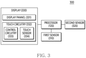
- the first sensor 310 may include the sensor module 176 illustrated in FIG. 1 .
- the first sensor 310 may be used to identify a change in a position of the electronic device 300.
- the first sensor 310 may be used to identify a movement state (or a movement distance) of the electronic device 300 or a change in the movement state.
- the first sensor 310 may be used to identify a posture of the electronic device 300 or a change in the posture of the electronic device 300.
- the first sensor 310 may include an acceleration sensor and/or a gyro sensor.
- the first sensor 310 may be referred to as an inertial sensor.
- the display 330 may include the display module 160 illustrated in FIG. 1 or FIG. 2 .
- the display 330 may include the display 210 illustrated in FIG. 2 .
- the display 330 may include a display panel 331 and touch circuitry 332.
- the display panel 331 may be used to display a screen or an image.
- the display panel 331 may provide an area capable of receiving a touch input.
- the area may correspond to a display area. However, it is not limited thereto.
- the touch circuitry 332 may include control circuitry 333 and a touch sensor 334.
- the control circuitry 333 may be used to control the touch sensor 334.
- the control circuitry 333 may process data for a plurality of values obtained from the touch sensor 334.
- the control circuitry 333 may generate or obtain, based on the processing, data to be provided to the processor 120.
- the control circuitry 333 may provide at least a portion of the data to the processor 120.
- the touch sensor 334 may obtain or identify the plurality of values via a plurality of nodes, in response to an external object at least partially contacted on the area.
- the plurality of nodes of the touch sensor 334 will be exemplified through FIGS. 6 , 7 , and 9 .
- the external object may include an object and/or a body part, which is contacted on the area.
- the external object may be a user's finger contacted on the area.
- the external object may be a stylus pen, associated with the electronic device 300, contacted on the area.
- the electronic device 300 when the electronic device 300 is positioned in a pocket, the external object may be an inner surface of the pocket that is contacted on the area.
- the external object may be an inner surface of the bag that is contacted on the area.
- the external object being contacted on the area may refer not only to the external object being directly contacted on the area, but also to the external object being positioned within a certain distance (or a predetermined distance) from the area.
- the external object being contacted on the area may indicate that the external object is positioned above the area. However, it is not limited thereto.
- the display 330 may include a single display.
- the display 330, which is the single display may include a planar portion.
- the display 330, which is the single display may include one or more curved portions extending from the planar portion.
- the display 330 may include a plurality of displays.
- at least one of the plurality of displays may be a flexible display or a deformable display.
- the at least one of the plurality of displays may be slid according to the movement of a housing of the electronic device 300.
- the at least one of the plurality of displays may be at least partially rolled into another housing of the electronic device 300.
- the plurality of displays may include a first display and a second display.
- the first display which is the flexible display, may have a plurality of states, as exemplified below through FIGS. 4 to 5 .
- the second display may be a display exposed through a second surface, different from a first surface of the housing of the electronic device 300 to which the first display is exposed. The second display exposed through the second surface will be exemplified through FIG. 5 . According to embodiments, the second display may not be included in the electronic device 300.
- the electronic device 300 which is the foldable-type electronic device, may provide various states through the first display.
- the various states may be exemplified through FIGS. 4 and 5 .
- FIG. 4 illustrates an unfolded state of an exemplary electronic device, according to an embodiment.
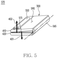
- FIG. 5 illustrates a folded state of an exemplary electronic device, according to an embodiment.
- an electronic device 300 may be in a state 400, which is the unfolded state in which a first housing 410 and a second housing 420 are fully unfolded out by a folding housing (a folding housing 565 illustrated in FIG. 5 ).
- the state 400 may mean a state in which a first direction 401 toward which a first surface 411 of a first housing 410 faces corresponds to a second direction 402 toward which a second surface 421 of a second housing 420 faces.
- the first direction 401 may be parallel to the second direction 402.
- the first direction 401 may be the same as the second direction 402.
- the first surface 411 may form substantially one flat surface with the second surface 421.
- an angle 403 between the first surface 411 and the second surface 421 may be 180 degrees.
- the state 400 may mean a state capable of providing an entire display area of the display 440, which is the first display indicated through the description of FIG. 3 , on substantially one flat surface.
- a display area of the display 440 may not include a curved surface.
- the unfolded state may be referred to as an outspread state or an outspreading state.
- a display area of the display 440 may include a second sensor 320.
- the second sensor 320 may be disposed under an area 480 within the display 440 corresponding to the first surface 411 of the first housing 410.
- the electronic device 300 may provide a state, which is the folded state in which the first housing 410 and the second housing 420 are folded in by the folding housing 565.
- the folded state including a state 570 may mean a state in which the first direction 401 toward which the first surface 411 (not illustrated in FIG. 5 ) faces is distinguished from the second direction 402 toward which the second surface 421 (not illustrated in FIG. 5 ) faces.
- an angle between the first direction 401 and the second direction 402 is substantially 180 degrees, and the first direction 401 and the second direction 402 may be distinguished from each other.
- an angle 573 between the first surface 411 and the second surface 421 may be substantially 0 degrees.
- the folded state may be referred to as a folding state.
- the electronic device 200 may provide the state 570 in which a display area (not illustrated in FIG. 5 ) of the display 440 corresponding to the first surface 411 substantially fully overlaps a display area (not illustrated in FIG. 5 ) of the display 440 corresponding to the second surface 421 as the first surface 411 and the second surface 421 face each other by the folding housing 565.
- the electronic device 200 may provide the state 570 in which the first direction 401 is substantially opposite to the second direction 402.
- the state 570 may mean a state in which a display area of the display 440 is obscured within the user's field of view looking at the electronic device 300. However, it is not limited thereto.
- the display 440 may be bent by rotation provided through the folding housing 565.
- a portion of the display area of the display 440 may be bent.
- the portion of the display area of the display 440 may be in a curvedly bent state to prevent damage to the display 440 within the state 570.
- it is not limited thereto.
- the processor 120 may identify an angle between the first direction 401 toward which the first surface 411 of the first housing 410 faces and the second direction 402 toward which the second surface 421 of the second housing 420 faces, through a hall sensor in the electronic device 300, the first sensor 310 in the electronic device 300, a rotation sensor in the folding housing 565, a stretch sensor in the electronic device 300, and/or the second sensor 320 in the electronic device 300.
- control circuitry 333 of the display 330 may obtain each of a plurality of values via each of the plurality of nodes of the touch sensor 334, based at least in part on the external object at least partially contacted on the area.
- the plurality of nodes may be evenly included within the area.
- the plurality of nodes may be spaced apart from each other by a certain interval.
- the plurality of nodes may be included within the area in one or more patterns.
- At least a portion of the plurality of values may indicate a state of the area that is at least partially changed according to the contact of the external object.
- at least a portion of the plurality of values may indicate a strength of the contact of the external object.
- the plurality of nodes and the plurality of values will be exemplified with reference to FIG. 6 .
- FIG. 6 illustrates an example of a plurality of nodes of a touch sensor that obtain a plurality of values based at least in part on an external object at least partially contacted on an area of a display panel.
- negative values among the plurality of values 610 may indicate that retransmission is caused within at least a portion of the plurality of nodes according to the contact of the external object.
- the negative values may indicate that noise is caused within the area 600 of the display panel 331 according to the contact of the external object.
- the negative values may be obtained through at least a portion of the plurality of nodes, when the strength of the contact of the external object is relatively small and an area in which the external object is contacted on the area 600 is relatively large.
- the control circuitry 333 may obtain first data based on the plurality of values.
- the first data may indicate at least a portion of a partial area within the area that includes a representative location of the contact of the external object.
- the representative location may indicate a location of a node obtaining a peak value to be exemplified below.
- the first data may indicate at least a portion of the partial area in which the external object is contacted on the area.
- the first data may be used to identify an attribute (e.g., a type and/or a location of input means) of the touch input.
- the first data may indicate a width (or horizontal length) of the partial area and/or a height (vertical length) of the partial area, based on the node and the first nodes.
- the first data may indicate a sum of values obtained through the node and the first nodes.
- the first data may indicate a center point of the partial area.
- the first data may indicate a location of the node.
- obtaining the first data may be exemplified through FIG. 7 .
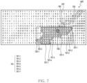
- FIG. 7 illustrates an example of obtaining first data based at least in part on an external object at least partially contacted on an area of a display panel.
- control circuitry 333 may identify a peak value (e.g., 409) among a plurality of values 610, by using the window, based at least in part on the contact of the external object. For example, the control circuitry 333 may identify a node 700 obtaining the peak value, in response to the contact of the external object.
- the peak value may be a maximum value among values included in the window, which are greater than or equal to the predetermined value (e.g., 200).
- the peak value may be a maximum value among values included in a partial area 720-1 or a partial area 720-2 to be exemplified below, which are greater than or equal to the predetermined value.
- the predetermined value e.g. 200
- the peak value may be a maximum value among values included in a partial area 720-1 or a partial area 720-2 to be exemplified below, which are greater than or equal to the predetermined value.
- the control circuitry 333 may identify a first node 701 including nodes 701-1, nodes 701-2, nodes 701-3, nodes 701-4, nodes 701-5, nodes 701-6, and nodes 701-7, based on the node 700 obtaining the peak value.
- the first nodes 701 may be nodes obtaining values greater than or equal to the first reference value (e.g., 100) among nodes around the node 700.
- the first reference value e.g. 100
- control circuitry 333 may obtain the first data, by utilizing the node 700 and the first nodes 701 or utilizing the peak value obtained via the node 700 and the values obtained via the first nodes 701. However, it is not limited thereto.
- the first data is not recommended for identifying whether the contact of the external object is the unintended touch input.
- FIG. 8 is a chart illustrating contact of various types of an external object classified according to first data and a peak value.
- a horizontal axis of chart 800 may indicate a peak value
- a vertical axis of chart 800 may indicate the first data.
- each of points 810 in the chart 800 may indicate an unintended touch input (e.g., a contact of an inner surface of a pocket including the electronic device 300)
- each of points 820 in the chart 800 may indicate an intended touch input (e.g., a touch input caused by a 5millimeter (mm) diameter conductive rod within a non-ground, a touch input from a thumb within ground, a touch input from a thumb within non-ground, a touch input from an index finger within ground, a touch input from an index finger within non-ground, a touch input from two fingers within ground (e.g., pinch zoom-in gesture on the area and/or pinch zoom-out gesture on the area), a touch input from two fingers within non-ground, and a palm swipe gesture on the area).
- mm millimeter
- a point 810-1 in the chart 800 may indicate an unintended touch input in which the peak value is about 300 and the first data is about 20,000.
- the point 820-1 in the chart 800 may indicate the intended touch input (e.g., the touch input from a thumb in ground) in which the peak value is about 800 and the first data is about 30,000.
- the points 810 in the chart 800 include a first group of points 810-2 indicating an unintended touch input having the peak value less than or equal to about 200 and the first data less than about 6,000, as well as a second group of points 810-3 indicating an unintended touch input having the peak value of about 200 to about 600 and the first data of about 5,000 to 30,000, identification of the unintended touch input through the peak value and the first data may ambiguous or unclear.
- at least a portion of the points 810 and at least a portion of the points 820-2 of the first group may overlap within a range 840 of peak values of about 200 to about 600.
- At least a portion of the points 810 and at least a portion of the points 820-2 of the first group may overlap within a range 850 of the first data of about 30,000 or less.
- identification (or classification) of the unintended touch input and the intended touch input through the peak value and the first data may be ambiguous or unclear.
- the control circuitry 333 may obtain another data distinct from the first data.
- the control circuitry 333 may obtain second data, which is the other data, based on the plurality of values.
- the second data may be obtained to identify whether the contact of the external object is the unintended touch input.
- the second data may be obtained to identify whether the contact of the external object is the contact of the inner surface of the pocket including the electronic device 300.
- the second data may indicate at least a portion of the plurality of nodes obtaining values within a reference range according to the contact of the external object.
- the second data may be obtained by the processor 120.
- the control circuitry 333 may provide the processor 120 with data (e.g., raw data) for obtaining the second data.
- data e.g., raw data
- the values within the reference range may include values equal to or greater than a second reference value among the plurality of values.
- the second reference value may be smaller than the first reference value.
- a strength of the contact of the unintended touch input on the area e.g., the contact of the inner surface of the pocket on the area
- the second reference value may be smaller than the first reference value.
- the extent of the contact of the unintended touch input on the area e.g., the contact of the inner surface of the pocket on the area
- the second reference value may be smaller than the first reference value.
- the values within the reference range may include values equal to or less than a third reference value among the plurality of values.
- each of the first reference value and the second reference value may be a positive number, while the third reference value may be a negative number.
- the contact of the unintended touch input on the area e.g., the contact of the inner surface of the pocket on the area
- the third reference value may be a negative number.
- the contact of the unintended touch input on the area may cause noise more frequently than the contact of the intended touch input on the area
- the third reference value may be a negative number.
- the extent of the contact of the unintended touch input on the area e.g., the contact of the inner surface of the pocket on the area
- an absolute value of the third reference value may be smaller than an absolute value of the first reference value.
- the values within the reference range may include values equal to or greater than the second reference value and values equal to or less than the third reference value, among the plurality of values.
- the second data may be different from the first data obtained based on the peak value.
- the second data may be different from the first data for identifying the partial area.
- the second data may be obtained to identify a state of the entire area according to the contact of the external object, unlike the first data obtained in relation to the partial area.
- control circuitry 333 may identify the second nodes obtaining the values greater than or equal to the second reference value and the third nodes obtaining the values less than or equal to the third reference value as at least a portion of the plurality of nodes. For example, the control circuitry 333 may obtain the second data, based on the second nodes and the third nodes. For example, the second data may indicate the number of the second nodes and the third nodes. For example, the second data may indicate a ratio of the number of the second nodes and the third nodes to the number of the plurality of nodes. However, it is not limited thereto. For example, obtaining the second data may be exemplified through FIG. 9 .
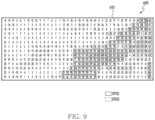
- FIG. 9 illustrates an example of obtaining second data based at least in part on an external object at least partially contacted on an area of a display panel.
- control circuitry 333 may identify the values greater than or equal to the second reference value (e.g., 30) among a plurality of values 610, based at least in part on the contact of the external object. For example, the control circuitry 333 may identify second nodes 910 obtaining the values greater than or equal to the second reference value, in response to the contact of the external object. For example, the control circuitry 333 may identify the values less than or equal to the third reference value (e.g., -30) among the plurality of values 610, based at least in part on the contact of the external object. For example, the control circuitry 333 may identify third nodes 920 obtaining the values less than or equal to the third reference value, in response to the contact of the external object. For example, the control circuitry 333 may obtain the second data based on the second nodes 910 and the third nodes 920.
- the second reference value e.g. 30
- the second data may be more suitable than the first data to identify whether the contact of the external object is the unintended touch input (or incorrect touch input). For example, since the unintended touch input of the external object (e.g., the contact of the inner surface of the pocket on the area) may have an intensity lower than the intended touch input contacted on the area, and may have the extent larger than the intended touch input contacted on the area, the second data may be more suitable to identify whether the contact of the external object is the unintended touch input than the first data obtained for identifying the partial area.
- the unintended touch input of the external object e.g., the contact of the inner surface of the pocket on the area
- the second data may be more suitable to identify whether the contact of the external object is the unintended touch input than the first data obtained for identifying the partial area.
- the number of second nodes 910 illustrated in FIG. 9 may be greater than the number of first nodes 701 illustrated in FIG. 7 .
- the number of second nodes 910 illustrated in FIG. 9 being greater than the number of first nodes 701 illustrated in FIG. 7 may indicate that the second data, unlike the first data, reflects a situation in which the strength of the contact of the external object on the area is relatively small.
- the fact that the second data includes third nodes 920 obtaining negative values in FIG. 9 may indicate that the second data, unlike the first data, reflects retransmission and noise due to the contact of the external object on the area.
- the fact that the extent occupied by the second nodes 910 and the third nodes 920 illustrated in FIG. 9 is larger than the extent occupied by the first nodes 701 illustrated in FIG. 7 indicates that the second data, unlike the first data, reflects a situation in which the extent where the external object is contacted on the area is relatively small.
- the second data is usable to identify whether the contact of the external object is the unintended touch input.
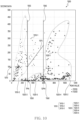
- FIG. 10 is a chart illustrating various types of a touch input classified according to second data and a peak value.
- a horizontal axis of chart 1000 may indicate a peak value
- a vertical axis of chart 1000 may indicate the second data (e.g., the number of the second nodes and the third nodes).
- each of the points 1010 in the chart 1000 may indicate an unintended touch input (e.g., a contact with an inner surface of a pocket including the electronic device 300)
- each of points 1020 in the chart 1000 may indicate an intended touch input(e.g., a touch input caused by a 5millimeter (mm) diameter conductive rod within a non-ground, a touch input from a thumb within ground, a touch input from a thumb within non-ground, a touch input from an index finger within ground, a touch input from an index finger within non-ground, a touch input from two fingers within ground (e.g., pinch zoom-in gesture on the area and/or pinch zoom-out gesture on the area), a touch input from two fingers within non-ground, and a palm swipe gesture on the area).
- mm millimeter
- a point 1010-1 in the chart 1000 may indicate the unintended touch input in which the peak value is about 350 and the second data is about 300.
- a point 1020-1 in the chart 1000 may indicate the intended touch input (e.g., touch input from a thumb within ground) in which the peak value is about 780, and the second data is about 200.
- the unintended touch input and the intended touch input may be classified or identified based on the line 1055.
- the second data may be used to identify whether the contact of the external object is the unintended touch input, unlike the first data.
- the intended touch input indicated by points 1020-3 of the second group positioned to the left of the line 1055 in the chart 1000 may be identified as the unintended touch input
- the unintended touch input indicated by points 1010-3 of the second group positioned to the right of the line 1055 in the chart 1000 may be identified as the intended touch input.
- the unintended touch input and the intended touch input may be classified or identified based on a line 1065 from a peak value 1060 (e.g., a peak value of a touch input from a conductive rod of 12 mm in diameter, 600).
- the intended touch input indicated by points 1020-5 of a fourth group positioned to the left of line 1065 in the chart 1000 may be identified as the unintended touch input.
- the unintended touch input and the intended touch input may be classified or identified based on a peak value 1050 (another reference number to be illustrated below) and a reference number 1070.
- the unintended touch input and the intended touch input may be classified based on a line 1075 from the peak value 1050 and the reference number 1070.
- the second data may be used to identify whether the contact of the external object is the unintended touch input, unlike the first data.
- control circuitry 333 may identify whether the contact of the external object is the intended touch input or the unintended touch input, based at least in part on the second data.
- control circuitry 333 may provide the first data to the processor 120 in order to provide feedback (or response) in response to the contact of the external object, based on identifying that the contact of the external object is the intended touch input.
- the processor 120 may provide the feedback (or the response) by executing a predetermined function based on the first data.
- the predetermined function may include changing a display within the area or initiating a display within the area.
- control circuitry 333 may refrain from, bypass, or omit providing the first data to the processor 120, based on identifying that the contact of the external object is the unintended touch input. For example, when the first data is provided to the processor 120, feedback on the contact of the external object may be provided, even though the contact of the external object is the unintended touch input, so the control circuitry 333 may refrain from, or bypass providing the first data to the processor 120.
- control circuitry 333 may provide the first data to the processor 120 to recognize the contact of the external object as a touch input (e.g., the intended touch input) on the area, or may refrain from providing the first data to the processor 120.
- a touch input e.g., the intended touch input
- the reference number may be used to estimate the electronic device 300 in the pocket.
- the number indicated by the second data being greater than or equal to the reference number may indicate that a probability of the electronic device 300 being positioned inside the pocket is higher than a probability of the electronic device 300 being positioned outside the pocket.
- the number indicated by the second data being greater than or equal to the reference number may indicate that a probability of the electronic device 300 being positioned outside the pocket is higher than a probability of the electronic device 300 being positioned inside the pocket.
- the first threshold value may be used to reduce providing of a response (or feedback) for the unintended touch input.
- the first threshold value may be a peak value 1050 in FIG. 10 .
- the first threshold value may be a peak value 1060 in FIG. 10 .
- control circuitry 333 may refrain from, block, or cease providing, to the processor 120, the first data obtained based on a node obtaining the peak value less than the first threshold value, based at least in part on the second data indicating the number greater than or equal to the reference number.
- control circuitry 333 may provide the processor 120 with the first data obtained based on a node obtaining a peak value greater than or equal to a second threshold value, based at least in part on the second data indicating the number less than the reference number.
- the second threshold value may be used to reduce providing the unintended touch input based on the estimation that the electronic device 300 is positioned outside the pocket.
- the second threshold value may be smaller than the first threshold value.
- the first threshold value is the peak value 1050 in FIG. 10
- the second threshold value may be a value smaller than the peak value 1050.
- the first threshold value is the peak value 1060 in FIG. 10
- the second threshold value may be the peak value 1050.
- control circuitry 333 may refrain from, block, or cease providing, to the processor 120, the first data obtained based on a node obtaining a peak value less than the second threshold value, based at least in part on the second data indicating the number less than the reference number.
- the control circuitry 333 may identify whether providing the first data to the processor 120 by utilizing the first threshold value for the contact of the external object contacted on a portion of the area, based at least in part on the second data indicating the number less than the reference number. For example, the control circuitry 333 may provide the processor 120 with the first data, in order to recognize the contact of the external object contacted on another portion (or remaining portion) of the area, distinct from the portion of the area, as a touch input (e.g., the intended touch input). For example, instead of using the second threshold value, the control circuitry 333 may use the first threshold value to identify whether to provide the first data to the processor 120 according to whether the external object is contacted on the portion of the area.
- FIG. 11 illustrates an example of a reference partial area within an area of a display panel, according to an embodiment.
- a processor 120 may display a screen 1100 within an area 600.
- the screen 1100 may include a lock screen.
- the screen 1100 may include a screen that is displayed while an always on display (AOD) mode is provided.
- AOD mode may mean a mode displaying an image (or screen) through a display 330 in a low power state.
- the processor 120 of the electronic device 300 may be in a low power state or a sleep state. However, it is not limited thereto.
- the screen 1100 may include an executable object capable of executing a predetermined function in response to a touch input.
- the screen 1100 may include an executable object 1110 and/or an executable object 1120.
- the executable object 1110 may be configured to execute a predetermined function (e.g., outgoing call) in response to a touch input in which a contact point 1111 within the executable object 1110 is moved in a predetermined direction 1112 and then released.
- the executable object 1120 may be configured to execute a predetermined function (e.g., enabling a camera) in response to a touch input in which a contact point 1121 within the executable object 1120 is moved in a predetermined direction 1122 and then released.
- a predetermined function e.g., enabling a camera
- the screen 1100 may be configured to execute a predetermined function in response to a touch input having a predetermined pattern.
- the screen 1100 may be configured to execute a predetermined function in response to a swipe input 1130 from an edge 1125 of the area 600.
- the screen 1100 may be configured to execute a predetermined function in response to a swipe input 1140 from an edge 1126 of the area 600.
- it is not limited thereto.
- the control circuitry 333 may identify whether providing the first data to the processor 120 by utilizing the first threshold value, based on the representative location (e.g., the representative location inside the reference partial area 1160) associated with the reference partial area 1160.
- the control circuitry 333 may provide the first data to the processor 120, based on the representative location (e.g., the representative location outside the reference partial area 1160) not associated with the reference partial area 1160.
- the representative location e.g., the representative location outside the reference partial area 1160
- control circuitry 333 may provide the processor with the first data obtained based on the node obtaining the peak value greater than or equal to the first threshold value, based at least in part on the second data indicating the number (e.g., the number of the second nodes and the third nodes) that is greater than or equal to the reference number and less than another reference number (e.g., the peak value 1050 in FIG. 10 ).
- the other reference number may be greater than the reference number.
- the peak value 1050 may be used to classify, based on the line 1075 in the chart 1000, the unintended touch input indicated by the points 1010-2 of the first group and the points 1010-3 of the second group, and the touch input indicated by the points 1020-2 of the first group, the peak value 1050 may be used as the other reference number.
- control circuitry 333 may identify whether to obtain the second data, according to whether a predetermined signal indicating the electronic device 300 positioned within the pocket is obtained, from the processor 120. For example, the control circuitry 333 may identify whether obtaining the predetermined signal from the processor 120.
- control circuitry 333 may obtain the second data in response to the predetermined signal. For example, the control circuitry 333 may identify whether to transmit the first data to the processor 120, based on the second data.
- control circuitry 333 may use the second data for identifying whether to transmit the first data to the processor 120, in response to the predetermined signal obtained from the processor 120 while the second data is being obtained.
- the predetermined signal may be provided to the control circuitry 333 from the processor 120, based on data obtained through the first sensor 310.
- the processor 120 may obtain third data indicating a posture of the electronic device 300 through a first sensor 310 (e.g., a gyro sensor).
- the processor 120 may obtain fourth data indicating a movement distance of the electronic device 300 through a first sensor 310 (e.g., an acceleration sensor).
- the processor 120 may provide the predetermined signal to the control circuitry 333, based on the third data indicating the posture distinct from a predetermined posture and the fourth data indicating the movement distance greater than or equal to a reference distance.
- the reference distance may be used to identify whether the electronic device 300 is moved in a state in which it is carried by the user.
- the electronic device moving more than the reference distance may indicate that the user is moving in a state in which the electronic device 300 is carried.
- the electronic device 300 moving more than the reference distance with a posture distinct from the predetermined posture may indicate that the electronic device 300 is being moved within a pocket.
- the electronic device 300 moving within a pocket may indicate that the electronic device 300 is in a state in which the probability of receiving the touch input on the area is relatively low.
- the processor 120 may provide, to the control circuitry 333, the predetermined signal based on the third data indicating the posture distinct from the predetermined posture and the fourth data indicating the movement distance greater than or equal to the reference distance, through an estimation that the electronic device 300 is in the state.
- the processor 120 may obtain sixth data indicating whether another external object is positioned within a predetermined distance from the electronic device 300 through a second sensor 320 (e.g., a proximity sensor).
- the processor 120 may provide, to the control circuitry 333, the predetermined signal based on the sixth data indicating that the other external object is positioned within the predetermined distance from the electronic device 300.
- the other external object being positioned within the predetermined distance from the electronic device 300 may indicate that the electronic device 300 is positioned within a pocket.
- control circuitry 333 may provide, to the processor 120, the first data, which is obtained based on the node obtaining the peak value greater than or equal to a fourth threshold value and is associated with another partial area within the area distinct from the reference partial area, wherein the fourth threshold value being less than or equal to the second threshold value.
- the fourth threshold value may indicate a threshold value used for the other partial area before using the second data, obtaining the second data, and/or obtaining the predetermined signal.
- the control circuitry 333 may refrain from providing, to the processor 120, the first data, which is obtained based on the node obtaining the peak value less than the fourth threshold value and is associated with the other partial area.
- the control circuitry 333 may obtain a plurality of other values through each of the plurality of nodes within a second time interval after a first time interval during which the plurality of values are obtained, based at least in part on the external object at least partially contacted on the area.
- a length of the first time interval and a length of a second time interval may be the same.
- a length of each of the first time interval and the second time interval may correspond to a period of a touch vertical synchronization signal.
- the control circuitry 333 may identify fourth nodes obtaining values greater than or equal to the second reference value among the plurality of nodes obtaining the plurality of other values.
- control circuitry 333 may identify fifth nodes obtaining values less than or equal to the third reference value among the plurality of nodes obtaining the plurality of other values. For example, the control circuitry 333 may obtain seventh data (e.g., the second data obtained within the second time interval) indicating the number of the fourth nodes and the fifth nodes. For example, the control circuitry 333 may be configured to provide, to the processor 120, the first data obtained based on the node obtaining the peak value greater than or equal to the first threshold value, based at least in part on the seventh data indicating the number that is greater than or equal to still another reference number (e.g., distinct from the reference number and the other reference number) less than the reference number.
- seventh data e.g., the second data obtained within the second time interval
- the control circuitry 333 may be configured to provide, to the processor 120, the first data obtained based on the node obtaining the peak value greater than or equal to the first threshold value, based at least in part on the seventh data indicating the number that is
- control circuitry 333 may provide, to the processor 120, the first data obtained based on the node obtaining the peak value greater than or equal to the second threshold value, based at least in part on the seventh data indicating the number less than the still another reference number. For example, the control circuitry 333 may refrain from providing, to the processor 120, the first data obtained based on the node obtaining the peak value less than the second threshold value, based at least in part on the seventh data indicating the number less than the still another reference number.
- control circuitry 333 may change a fourth reference value (e.g., the predetermined value) for identifying the peak value to a fifth reference value greater than the fourth reference value, based at least in part on the second data indicating the number greater than the reference number. For example, the control circuitry 333 may change the fourth reference value to the fifth reference value, in order to reduce obtaining the first data.
- a fourth reference value e.g., the predetermined value
- the control circuitry 333 may obtain the plurality of other values within the second time interval after the first time interval during which the plurality of values are obtained, through each of the plurality of nodes, based at least in part on the external object. For example, a difference between the fourth reference value (e.g., the predetermined value) and a sixth reference value predefined within the control circuitry 333 to identify a peak value among the plurality of other values may be reduced based at least in part on the second data indicating the number greater than or equal to the reference number.
- the fourth reference value e.g., the predetermined value
- a sixth reference value predefined within the control circuitry 333 may be reduced based at least in part on the second data indicating the number greater than or equal to the reference number.
- the sixth reference value may be a value predefined within the control circuitry 333 to identify a touch input (e.g., a contact point following an initial contact point of a drag input) after an initial touch input (the initial contact point of the drag input) on the area.
- the control circuitry 333 may increase the sixth reference value based at least in part on the second data.
- the control circuitry 333 may identify a first value by adding values obtained through the node and the first nodes. For example, the control circuitry 333 may obtain the first data, based on the first value greater than or equal to a seventh reference value. For example, the control circuitry 333 may obtain the plurality of other values within the second time interval after the first time interval during which the plurality of values are obtained, through each of the plurality of nodes, based at least in part on the external object. For example, the control circuitry 333 may identify another node obtaining a peak value among the plurality of other values by using the window, among the plurality of nodes.
- control circuitry 333 may identify fourth nodes around the other node, obtaining values greater than or equal to the first reference value, among the plurality of nodes. For example, the control circuitry 333 may identify a second value by adding values obtained through the other node and the fourth nodes. For example, the control circuitry 333 may obtain eighth data indicating another partial area that is at least partially different from the partial area, based on the second value greater than or equal to an eighth reference value, wherein the eighth reference value being smaller than the seventh reference value. A difference between the seventh reference value and the eighth reference value may be reduced based at least in part on the second data indicating the number greater than or equal to the reference number.
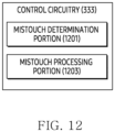
- control circuitry 333 may include a mistouch determination portion 1201 and a mistouch processing portion 1203.
- the mistouch processing portion 1203 may be configured to, based on the identification result of the mistouch determination portion 1201, provide the first data to the processor 120 or refrain from providing the first data to the processor 120.
- FIG. 12 illustrates an example in which the mistouch determination portion 1201 and/or the mistouch processing portion 1203 are included in the control circuitry 333, but it is for convenience of explanation.
- the mistouch determination portion 1201 and/or the mistouch processing portion 1203 may be included in the processor 120. However, it is not limited thereto.
- FIG. 13 illustrates an example of an operation of control circuitry according to an embodiment.
- control circuitry 333 may identify whether the predetermined signal is received from the processor 120.
- the predetermined signal may indicate a signal provided from the processor 120 to the control circuitry 333 based on the estimation that the electronic device 300 is positioned within a pocket.
- the control circuitry 333 may execute operation 1305, and execute operation 1303 otherwise.
- the control circuitry 333 may refrain from obtaining or using the second data while the predetermined signal is not received. For example, since the predetermined signal being not received may indicate that the electronic device 300 is positioned outside a pocket, the control circuitry 333 may refrain from obtaining the second data in order to reduce the load. For example, since the predetermined signal being not received may indicate that the electronic device 300 is positioned outside a pocket, the control circuitry 333 may refrain from using the second data in order to enhance performance of recognizing the intended touch input. However, it is not limited thereto.
- the control circuitry 333 may identify whether the second data satisfies a reference condition. For example, the fact that the second data satisfies the reference condition may indicate that the number indicated by the second data is greater than or equal to the reference number. For example, the fact that the second data does not satisfy the reference condition may indicate that the number is less than the reference number. However, it is not limited thereto.
- the control circuitry 333 may execute operation 1311 based at least in part on the second data satisfying the reference condition, and otherwise execute operation 1309.
- the control circuitry 333 may provide the first data to the processor 120 or refrain from providing the first data to the processor 120, according to a result of comparison between the peak value and the first threshold value. For example, since the peak value being greater than or equal to the first threshold value may indicate that the contact of the external object is the intended touch input, the control circuitry 333 may provide, to the processor 120, the first data, for recognizing the intended touch input. For example, since the peak value being less than the first threshold value may indicate that the contact of the external object is the unintended touch input, the control circuitry 333 may refrain from providing, to the processor 120, the first data, in order to reduce providing a response according to the contact of the external object.
- the control circuitry 333 may provide the first data to the processor 120 or refrain from providing the first data to the processor 120, according to a result of comparison between the peak value and the second threshold value. For example, since the fact that the second data does not satisfy the reference condition may indicate that the electronic device 300 may be outside the pocket, the control circuitry 333 may compare the peak value with the second threshold value less than the first threshold value. For example, since the peak value being greater than or equal to the second threshold value may indicate that the contact of the external object is the intended touch input, the control circuitry 333 may provide, to the processor 120, the first data, for recognizing the intended touch input.
- control circuitry 333 may refrain from providing the first data to the processor 120, in order to reduce providing a response according to the contact of the external object.
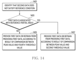
- FIG. 14 illustrates an example of an operation of processing first data, based on a relationship between the first data and a reference partial area, according to an embodiment.
- Operations 1401 to 1407 of FIG. 14 may be included in operations 1307 and 1309 of FIG. 13 . However, it is not limited thereto.
- the control circuitry 333 may identify that the second data does not satisfy the reference condition.
- the control circuitry 333 may identify, in response to the identification, whether the first data is associated with the reference partial area. For example, since the reference partial area is an area providing a response (or feedback) for a touch input, the control circuitry 333 may identify whether the partial area indicated by the first data overlaps the reference partial area. For example, the control circuitry 333 may execute operation 1407 based on the first data associated with the reference partial area, and execute operation 1409 based on the first data that is not associated with the reference partial area.
- the control circuitry 333 may provide the first data to the processor 120 or refrain from providing the first data to the processor 120, according to a result of comparison between the peak value and the fourth threshold value.
- the fourth threshold value may be smaller than the second threshold value.
- the fourth threshold value being smaller than the second threshold value may indicate that a possibility in which the contact of the external object is identified as the intended touch input is high.
- the first data being associated with the reference partial area may indicate that the first data is associated with the other partial area within the area that is distinct from the reference partial area.
- the control circuitry 333 may identify a threshold value for the other partial area as the fourth threshold value. For example, the control circuitry 333 may provide the first data to the processor 120, when the peak value is greater than or equal to the fourth threshold value. For example, the control circuitry 333 may refrain from providing the first data to the processor 120, when the peak value is less than the fourth threshold value.
- FIG. 15 illustrates an example of an operation of processing first data, based on whether second data satisfies another reference condition, according to an embodiment.
- Operations 1501 to 1509 of FIG. 15 may be included in operations 1307 and 1311 of FIG. 13 . However, it is not limited thereto.
- control circuitry 333 may identify that the second data satisfies the reference condition.
- the control circuitry 333 may identify, in response to the identification, whether the second data satisfies another reference condition.
- the fact that the second data satisfies the other reference condition may indicate that the number indicated by the second data is greater than or equal to the other reference number.
- the fact that the second data does not satisfy the other reference condition may indicate that the number is less than the other reference number.
- the control circuitry 333 may execute operation 1507 based at least in part on the second data satisfying the other reference condition, and otherwise execute operation 1505.
- control circuitry 333 may provide the first data to the processor 120 or refrain from providing the first data to the processor 120, according to a result of comparison between the peak value and the first threshold value.
- operation 1505 may correspond to operation 1311.
- the control circuitry 333 may provide the first data to the processor 120 or refrain from providing the first data to the processor 120, according to a result of comparison between the peak value and the third threshold value. For example, the control circuitry 333 may provide the first data to the processor 120, based at least in part on the peak value greater than or equal to the third threshold value. For example, the control circuitry 333 may refrain from providing the first data to the processor 120, based at least in part on the peak value less than the third threshold value.
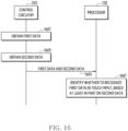
- FIG. 16 illustrates an example of an operation of a processor, according to an embodiment.
- control circuitry 333 may obtain the first data based at least in part on the contact of the external object.
- the first data may be obtained based on a period of the touch vertical synchronization signal.
- control circuitry 333 may provide the first data and the second data to the processor 120.
- control circuitry 333 may, in response to obtaining the first data and the second data, provide the first data and the second data to the processor 120, in order to enable the processor 120 to identify whether the contact of the external object is the unintended touch input or the intended touch input.
- the processor 120 may obtain the first data and the second data from the control circuitry 333.
- the processor 120 may, in response to obtaining the first data and the second data, identify whether to recognize the first data as a touch input based at least in part on the second data. For example, the processor 120 may identify whether the contact of the external object is the intended touch input or the unintended touch input, through execution of operation 1307, operation 1403, and/or operation 1503. For example, the processor 120 may obtain a response for the contact of the external object, based on identifying that the contact of the external object is the intended touch input. For example, the processor 120 may change a display state of the display 330, based on the response. For example, the processor 120 may cease, refrain from, or bypass providing the response, based on identifying that the contact of the external object is the unintended touch input. For example, the processor 120 may ignore the first data, based on identifying that the contact of the external object is the unintended touch input.
- the electronic device 300 may reduce execution of operations unintended by the user within the electronic device 300, through obtaining and/or using of the second data.
- an electronic device 300 may comprise a display panel 331 including an area 600 capable of receiving a touch input.
- the electronic device 300 may comprise touch circuitry 332 including control circuitry 333, and a touch sensor 334, the touch sensor 334 including a plurality of nodes in the area 600.
- the electronic device 300 may comprise a processor 120.
- the control circuitry 333 may be configured to, based at least in part on an external object at least partially contacted on the area 600, respectively obtain a plurality of values via each of the plurality of nodes.
- control circuitry 333 may be configured to, based on the plurality of values, obtain first data indicating a partial area 720-1; 720-2 in the area 600 that includes a representative location of the contact of the external object. According to an embodiment, the control circuitry 333 may be configured to, based on the plurality of the values, obtain second data indicating at least a portion of the plurality of the nodes obtaining values within a reference range according to the contact of the external object. According to an embodiment, the control circuitry 333 may be configured to, based at least in part on the second data, provide, to the processor 120, the first data, for recognizing the contact of the external object as a touch input on the area 600, or refrain from providing, to the processor 120, the first data.
- control circuitry 333 may be configured to, using a window having a predetermined size, identify, from among the plurality of nodes, a node 700 obtaining a peak value from among the plurality of values. According to an embodiment, the control circuitry 333 may be configured to identify, from among the plurality of nodes, first nodes 701, being around the node 700, obtaining values that are equal to or greater than a first reference value. According to an embodiment, the control circuitry 333 may be configured to, based on the node 700 and the first nodes 701, obtain the first data.
- control circuitry 333 may be configured to identify, from among the plurality of nodes, second nodes 910 obtaining values equal to or greater than a second reference value and third nodes 920 obtaining values equal to or less than a third reference value as the at least a portion of the plurality of nodes, the second reference value being less than the first reference value, the third reference value being less than the second reference value. According to an embodiment, the control circuitry 333 may be configured to, based on the second nodes 910 and the third nodes 920, obtain the second data.
- each of the first reference value and the second reference value may be a positive number.
- the third reference value may be a negative number.
- an absolute value of the third reference value may be less than an absolute value of the first reference value.
- the second data may indicate the number of the second nodes 910 and the third nodes 920.
- control circuitry 333 may be configured to, based at least in part on the second data indicating the number equal to or greater than a reference number, provide, to the processor 120, the first data obtained based on the node 700 obtaining the peak value equal to or greater than a first threshold value, and refrain from providing, to the processor 120, the first data obtained based on the node 700 obtaining the peak value less than the first threshold value.
- control circuitry 333 may be configured to, based at least in part on the second data indicating the number less than the reference number, provide, to the processor 120, the first data obtained based on the node 700 obtaining the peak value equal to or greater than a second threshold value, the second threshold value being less than the first threshold value, and refrain from providing, to the processor 120, the first data obtained based on the node 700 obtaining the peak value less than the second threshold value.
- control circuitry 333 may be configured to, based at least in part on the second data indicating the number being equal to or greater than the reference number and being less than another reference number, the another reference number being greater than the reference number, provide, to the processor 120, the first data obtained based on the node 700 obtaining the peak value equal to or greater than the first threshold value, and refrain from providing, to the processor 120, the first data obtained based on the node 700 obtaining the peak value less than the first threshold value.
- control circuitry 333 may be configured to, based at least in part on the second data indicating the number being equal to or great than the another reference number, identify a third threshold value corresponding to the number, provide, to the processor 120, the first data obtained based on the node 700 obtaining the peak value equal to or greater than the third threshold value, and refrain from providing, to the processor 120, the first data obtained based on the node 700 obtaining the peak value less than the third threshold value.
- control circuitry 333 may be configured to identify whether obtaining, from the processor 120, a predetermined signal indicating the electronic device 300 positioned in a pocket. According to an embodiment, the control circuitry 333 may be configured to, in response to the predetermined signal, obtain the second data. According to an embodiment, the control circuitry 333 may be configured to, before the predetermined signal is obtained, refrain from obtaining the second data, or refrain from utilizing the second data for identifying whether providing the first data to the processor 120.
- the electronic device 300 may further comprise an inertial sensor 310.
- the processor 120 may be configured to obtain, via the at least one inertial sensor 310, third data indicating a posture of the electronic device 300 and fourth data indicating a movement distance of the electronic device 300.
- the processor 120 may be configured to, based on the third data indicating the posture of the electronic device 300 different from a predetermined posture and the fourth data indicating the movement distance of the electronic device 300 equal to or greater than a reference distance, provide, to the control circuitry 333, the predetermined signal.
- control circuitry 333 may be configured to, based at least in part on the second data indicating the number less than the reference number, identify whether the first data is associated with a reference partial area 1160 in the area. According to an embodiment, the control circuitry 333 may be configured to provide, to the processor 120, the first data, obtained based on the node 700 obtaining the peak value equal to or greater than the second threshold value, associated with the reference partial area 1160. According to an embodiment, the control circuitry 333 may be configured to refrain from providing, to the processor 120, the first data, obtained based on the node 700 obtaining the peak value less than the second threshold value, associated with the reference partial area 1160.
- control circuitry 333 may be configured to provide, to the processor 120, the first data, associated with another partial area different from the reference partial area 1160, obtained based on the node 700 obtaining the peak value equal to or greater than a fourth threshold value, the fourth threshold value being less than the second threshold value. According to an embodiment, the control circuitry 333 may be configured to refrain from providing, to the processor 120, the first data, associate with the other partial area, obtained based on the node 700 obtaining the peak value less than the fourth threshold value.
- the electronic device 300 may further comprise an illuminance sensor 320.
- the processor 120 may be configured to obtain fifth data indicating a brightness around the electronic device, via the illuminance sensor 320.
- the processor 120 may be configured to, further based on the fifth data indicating the brightness less than a reference brightness, provide, to the control circuitry 333, the predetermined signal.
- the electronic device 300 may further comprise a proximity sensor 320.
- the processor 120 may be configured to obtain fifth data indicating whether another external object is positioned within a predetermined distance from the electronic device 300, via the proximity sensor 320.
- the processor 120 may be configured to, further based on the fifth data indicating that the other external object is positioned within the predetermined distance from the electronic device 300, provide, to the control circuitry 333, the predetermined signal.
- control circuitry 333 may be configured to, based at least in part on the external object, obtain a plurality of other values via each of the plurality of nodes in a second time interval after a first time interval, the first time interval obtaining the plurality of values. According to an embodiment, the control circuitry 333 may be configured to identify, from among the plurality of nodes obtaining the plurality of other values, fourth nodes obtaining values equal to or greater than the second reference value and fifth nodes obtaining values equal to or less than the third reference value. According to an embodiment, the control circuitry 333 may be configured to obtain third data indicating a number of the fourth nodes and the fifth nodes.
- control circuitry 333 may be configured to, based at least in part on the third data indicating the number equal to or greater than another reference number, provide, to the processor 120, the first data obtained based on the node obtaining the peak value equal to or greater than the first threshold value, the another reference number being smaller than the reference number, and refrain from providing, to the processor 120, the first data obtained based on the node obtaining the peak value less than the first threshold value.
- control circuitry 333 may be configured to, based at least in part on the second data indicating the number equal to or greater than a reference number, change a fourth reference value for identifying the peak value to a fifth reference value greater than the fourth reference value.
- control circuitry 333 may be configured to, based at least in part on the external object, obtain a plurality of other values within a second time interval after a first time interval during which the plurality of values are obtained, through each of the plurality of nodes. A difference between a fourth reference value used for identifying the peak value among the plurality of values and a fifth reference value used for identifying the peak value among the plurality of other values may be reduced, based at least in part on the second data indicating the number greater than or equal to a reference number.
- control circuitry 333 may be configured to identify a first value by adding values obtained through the node and the first nodes. According to an embodiment, the control circuitry 333 may be configured to obtain the first data, based on the first value greater than or equal to a fourth reference value. According to an embodiment, the control circuitry 333 may be configured to, based at least in part on the external object, obtain a plurality of other values ,within a second time interval after a first time interval during which the plurality of values are obtained, through each of the plurality of nodes. According to an embodiment, the control circuitry 333 may be configured to identify, among the plurality of nodes, another node obtaining a peak value from among the plurality of other values, by using the window.
- the processor 120 may be configured to identify a response for the contact of the external object, based on the first data. According to an embodiment, the processor 120 may be configured to change a display within the area, based at least in part on the response.
- an electronic device 300 may comprise a display panel 331 including an area 600 capable of receiving a touch input.
- the electronic device 300 may comprise touch circuitry 332 including control circuitry 333, and a touch sensor 334, the touch sensor 334 including a plurality of nodes in the area 600.
- the electronic device 300 may comprise a processor 120.
- the control circuitry 333 may be configured to, based at least in part on an external object at least partially contacted on the area 600, respectively obtain a plurality of values via each of the plurality of nodes.
- control circuitry 333 may be configured to identify, from among the plurality of nodes, second nodes obtaining values equal to or greater than a second reference value, the second reference value less than the first reference value. According to an embodiment, the control circuitry 333 may be configured to identify, from among the plurality of nodes, third nodes obtaining values equal to or less than a third reference value, the third reference value less than the second reference value. According to an embodiment, the control circuitry 333 may be configured to, based on the second nodes and the third nodes, obtain the second data.
- each of the first reference value and the second reference value may be a positive number.
- the third reference value may be a negative number.
- an absolute value of the third reference value may be less than an absolute value of the first reference value.
- the electronic device may be one of various types of electronic devices.
- the electronic devices may include, for example, a portable communication device (e.g., a smartphone), a computer device, a portable multimedia device, a portable medical device, a camera, a wearable device, or a home appliance. According to an embodiment of the disclosure, the electronic devices are not limited to those described above.
- each of such phrases as “A or B,” “at least one of A and B,” “at least one of A or B,” “A, B, or C,” “at least one of A, B, and C,” and “at least one of A, B, or C,” may include any one of or all possible combinations of the items enumerated together in a corresponding one of the phrases.
- such terms as “1st” and “2nd,” or “first” and “second” may be used to simply distinguish a corresponding component from another, and does not limit the components in other aspect (e.g., importance or order).
- an element e.g., a first element
- operatively or “communicatively”, as “coupled with,” or “connected with” another element
- the element may be coupled with the other element directly (e.g., wiredly), wirelessly, or via a third element.
- Various embodiments as set forth herein may be implemented as software (e.g., the program 140) including one or more instructions that are stored in a storage medium (e.g., internal memory 136 or external memory 138) that is readable by a machine (e.g., the electronic device 101).
- a processor e.g., the processor 120
- the machine e.g., the electronic device 101
- the one or more instructions may include a code generated by a complier or a code executable by an interpreter.
- the machine-readable storage medium may be provided in the form of a non-transitory storage medium.
- non-transitory simply means that the storage medium is a tangible device, and does not include a signal (e.g., an electromagnetic wave), but this term does not differentiate between a case in which data is semi-permanently stored in the storage medium and a case in which the data is temporarily stored in the storage medium.
- operations performed by the module, the program, or another component may be carried out sequentially, in parallel, repeatedly, or heuristically, or one or more of the operations may be executed in a different order or omitted, or one or more other operations may be added.
Landscapes
- Engineering & Computer Science (AREA)
- General Engineering & Computer Science (AREA)
- Theoretical Computer Science (AREA)
- Human Computer Interaction (AREA)
- Physics & Mathematics (AREA)
- General Physics & Mathematics (AREA)
- User Interface Of Digital Computer (AREA)
Applications Claiming Priority (3)
| Application Number | Priority Date | Filing Date | Title |
|---|---|---|---|
| KR20220087572 | 2022-07-15 | ||
| KR1020220099277A KR20240010367A (ko) | 2022-07-15 | 2022-08-09 | 외부 객체의 접촉을 처리하는 터치 회로를 포함하는 디스플레이를 포함하는 전자 장치 |
| PCT/KR2023/006773 WO2024014686A1 (ko) | 2022-07-15 | 2023-05-18 | 외부 객체의 접촉을 처리하는 터치 회로를 포함하는 디스플레이를 포함하는 전자 장치 |
Publications (2)
| Publication Number | Publication Date |
|---|---|
| EP4535151A1 true EP4535151A1 (de) | 2025-04-09 |
| EP4535151A4 EP4535151A4 (de) | 2025-09-03 |
Family
ID=89536820
Family Applications (1)
| Application Number | Title | Priority Date | Filing Date |
|---|---|---|---|
| EP23839780.6A Pending EP4535151A4 (de) | 2022-07-15 | 2023-05-18 | Elektronische vorrichtung mit anzeige mit berührungsschaltung zur verarbeitung des kontakts eines externen objekts |
Country Status (2)
| Country | Link |
|---|---|
| EP (1) | EP4535151A4 (de) |
| WO (1) | WO2024014686A1 (de) |
Family Cites Families (7)
| Publication number | Priority date | Publication date | Assignee | Title |
|---|---|---|---|---|
| KR101823476B1 (ko) * | 2011-06-14 | 2018-01-30 | 엘지전자 주식회사 | 이동 단말기 및 이를 이용한 터치 제어 방법 |
| KR20150103455A (ko) * | 2014-03-03 | 2015-09-11 | 삼성전기주식회사 | 터치스크린 장치 및 터치 감지 방법 |
| US10216330B2 (en) * | 2014-07-02 | 2019-02-26 | 3M Innovative Properties Company | Touch systems and methods including rejection of unintentional touch signals |
| KR102569170B1 (ko) * | 2018-08-09 | 2023-08-22 | 삼성전자 주식회사 | 사용자 입력이 유지되는 시간에 기반하여 사용자 입력을 처리하는 방법 및 장치 |
| US11669202B2 (en) * | 2019-02-19 | 2023-06-06 | Samsung Electronics Co., Ltd. | Touch circuit for processing touch-associated data, electronic device comprising touch circuit, and method for operating same |
| KR20200101254A (ko) * | 2019-02-19 | 2020-08-27 | 삼성전자주식회사 | 터치와 연관된 데이터를 처리하는 터치 회로, 터치 회로를 포함하는 전자 장치, 및 그 동작 방법 |
| US11256367B2 (en) * | 2019-09-27 | 2022-02-22 | Apple Inc. | Techniques for handling unintentional touch inputs on a touch-sensitive surface |
-
2023
- 2023-05-18 EP EP23839780.6A patent/EP4535151A4/de active Pending
- 2023-05-18 WO PCT/KR2023/006773 patent/WO2024014686A1/ko not_active Ceased
Also Published As
| Publication number | Publication date |
|---|---|
| WO2024014686A1 (ko) | 2024-01-18 |
| EP4535151A4 (de) | 2025-09-03 |
| US20250147612A1 (en) | 2025-05-08 |
Similar Documents
| Publication | Publication Date | Title |
|---|---|---|
| US11244658B1 (en) | Electronic device capable of expanding display region and method for controlling screen thereof | |
| EP4175267A1 (de) | Elektronische vorrichtung zur bereitstellung eines gemeinsamen bildschirms und eines privaten bildschirms und steuerungsverfahren dafür | |
| EP4216048A1 (de) | Elektronische vorrichtung und verfahren zur steuerung einer flexiblen anzeige | |
| US12079044B2 (en) | Electronic device having flexible display and method for providing control panel according to mode change thereof | |
| US20250217091A1 (en) | Electronic device and method for controlling screen displayed on flexible display | |
| EP4321963B1 (de) | Faltbare elektronische vorrichtung mit mehreren fingerabdrucksensoren | |
| EP4242823A1 (de) | Elektronische vorrichtung mit flexibler anzeige und verfahren zum betrieb davon | |
| US20230247130A1 (en) | Method for providing screen by using flexible display, and electronic device supporting same | |
| US11984054B2 (en) | Electronic device having flexible display | |
| US12079399B2 (en) | Electronic device, and method for displaying electronic pen pointer thereof | |
| US12277287B2 (en) | Electronic device including flexible display and controlling display of a graphic user interface based on sensed stress values caused by a touch on the flexible display | |
| US12360577B2 (en) | Image capture method and electronic device therefor | |
| EP4641361A1 (de) | Elektronische vorrichtung und verfahren zur erkennung der eingabe in eine flexible anzeige | |
| EP4400948A1 (de) | Elektronische vorrichtung zur zustandserkennung unter verwendung eines sensors | |
| EP4535151A1 (de) | Elektronische vorrichtung mit anzeige mit berührungsschaltung zur verarbeitung des kontakts eines externen objekts | |
| US11989375B2 (en) | Electronic device for typo correction and method thereof | |
| US12591328B2 (en) | Electronic device including display including touch circuit that processes contact of external object | |
| EP4600791A1 (de) | Wearable-vorrichtung und verfahren zur identifizierung von berührungseingabe und nichttransitorisches computerlesbares speichermedium | |
| KR102925761B1 (ko) | 디스플레이 패널 상의 외부 객체의 접촉을 처리하는 전자 장치 및 방법 | |
| US12073043B2 (en) | Electronic device and method for detecting touch input thereof | |
| KR20240010367A (ko) | 외부 객체의 접촉을 처리하는 터치 회로를 포함하는 디스플레이를 포함하는 전자 장치 | |
| US12430007B2 (en) | Electronic device including deformable display and operating method thereof | |
| EP4379498A1 (de) | Anzeigesteuerungsverfahren und elektronische vorrichtung zur unterstützung davon | |
| EP4642017A1 (de) | Elektronische vorrichtung mit flexibler anzeige und verfahren zur identifizierung eines gefalteten oder nicht gefalteten zustands | |
| EP4343526A1 (de) | Elektronische vorrichtung mit unterstützung eines einhändigen betriebsmodus und betriebsverfahren für elektronische vorrichtung |
Legal Events
| Date | Code | Title | Description |
|---|---|---|---|
| STAA | Information on the status of an ep patent application or granted ep patent |
Free format text: STATUS: THE INTERNATIONAL PUBLICATION HAS BEEN MADE |
|
| PUAI | Public reference made under article 153(3) epc to a published international application that has entered the european phase |
Free format text: ORIGINAL CODE: 0009012 |
|
| STAA | Information on the status of an ep patent application or granted ep patent |
Free format text: STATUS: REQUEST FOR EXAMINATION WAS MADE |
|
| 17P | Request for examination filed |
Effective date: 20241230 |
|
| AK | Designated contracting states |
Kind code of ref document: A1 Designated state(s): AL AT BE BG CH CY CZ DE DK EE ES FI FR GB GR HR HU IE IS IT LI LT LU LV MC ME MK MT NL NO PL PT RO RS SE SI SK SM TR |
|
| A4 | Supplementary search report drawn up and despatched |
Effective date: 20250806 |
|
| RIC1 | Information provided on ipc code assigned before grant |
Ipc: G06F 3/06 20060101AFI20250731BHEP Ipc: G06F 3/046 20060101ALI20250731BHEP Ipc: G06F 3/041 20060101ALI20250731BHEP |
|
| DAV | Request for validation of the european patent (deleted) | ||
| DAX | Request for extension of the european patent (deleted) |