EP4534936A2 - Gerät - Google Patents
Gerät Download PDFInfo
- Publication number
- EP4534936A2 EP4534936A2 EP25159352.1A EP25159352A EP4534936A2 EP 4534936 A2 EP4534936 A2 EP 4534936A2 EP 25159352 A EP25159352 A EP 25159352A EP 4534936 A2 EP4534936 A2 EP 4534936A2
- Authority
- EP
- European Patent Office
- Prior art keywords
- sensor
- supporter
- appliance
- door
- knock
- Prior art date
- Legal status (The legal status is an assumption and is not a legal conclusion. Google has not performed a legal analysis and makes no representation as to the accuracy of the status listed.)
- Pending
Links
Images










Classifications
-
- F—MECHANICAL ENGINEERING; LIGHTING; HEATING; WEAPONS; BLASTING
- F25—REFRIGERATION OR COOLING; COMBINED HEATING AND REFRIGERATION SYSTEMS; HEAT PUMP SYSTEMS; MANUFACTURE OR STORAGE OF ICE; LIQUEFACTION SOLIDIFICATION OF GASES
- F25D—REFRIGERATORS; COLD ROOMS; ICE-BOXES; COOLING OR FREEZING APPARATUS NOT OTHERWISE PROVIDED FOR
- F25D23/00—General constructional features
- F25D23/02—Doors; Covers
- F25D23/028—Details
-
- F—MECHANICAL ENGINEERING; LIGHTING; HEATING; WEAPONS; BLASTING
- F24—HEATING; RANGES; VENTILATING
- F24C—DOMESTIC STOVES OR RANGES ; DETAILS OF DOMESTIC STOVES OR RANGES, OF GENERAL APPLICATION
- F24C15/00—Details
- F24C15/008—Illumination for oven cavities
-
- F—MECHANICAL ENGINEERING; LIGHTING; HEATING; WEAPONS; BLASTING
- F24—HEATING; RANGES; VENTILATING
- F24C—DOMESTIC STOVES OR RANGES ; DETAILS OF DOMESTIC STOVES OR RANGES, OF GENERAL APPLICATION
- F24C15/00—Details
- F24C15/02—Doors specially adapted for stoves or ranges
-
- F—MECHANICAL ENGINEERING; LIGHTING; HEATING; WEAPONS; BLASTING
- F24—HEATING; RANGES; VENTILATING
- F24C—DOMESTIC STOVES OR RANGES ; DETAILS OF DOMESTIC STOVES OR RANGES, OF GENERAL APPLICATION
- F24C3/00—Stoves or ranges for gaseous fuels
- F24C3/12—Arrangement or mounting of control or safety devices
- F24C3/126—Arrangement or mounting of control or safety devices on ranges
- F24C3/128—Arrangement or mounting of control or safety devices on ranges in baking ovens
-
- F—MECHANICAL ENGINEERING; LIGHTING; HEATING; WEAPONS; BLASTING
- F24—HEATING; RANGES; VENTILATING
- F24C—DOMESTIC STOVES OR RANGES ; DETAILS OF DOMESTIC STOVES OR RANGES, OF GENERAL APPLICATION
- F24C7/00—Stoves or ranges heated by electric energy
- F24C7/08—Arrangement or mounting of control or safety devices
- F24C7/082—Arrangement or mounting of control or safety devices on ranges, e.g. control panels, illumination
- F24C7/085—Arrangement or mounting of control or safety devices on ranges, e.g. control panels, illumination on baking ovens
-
- F—MECHANICAL ENGINEERING; LIGHTING; HEATING; WEAPONS; BLASTING
- F25—REFRIGERATION OR COOLING; COMBINED HEATING AND REFRIGERATION SYSTEMS; HEAT PUMP SYSTEMS; MANUFACTURE OR STORAGE OF ICE; LIQUEFACTION SOLIDIFICATION OF GASES
- F25D—REFRIGERATORS; COLD ROOMS; ICE-BOXES; COOLING OR FREEZING APPARATUS NOT OTHERWISE PROVIDED FOR
- F25D29/00—Arrangement or mounting of control or safety devices
-
- G—PHYSICS
- G01—MEASURING; TESTING
- G01H—MEASUREMENT OF MECHANICAL VIBRATIONS OR ULTRASONIC, SONIC OR INFRASONIC WAVES
- G01H1/00—Measuring characteristics of vibrations in solids by using direct conduction to the detector
-
- G—PHYSICS
- G01—MEASURING; TESTING
- G01P—MEASURING LINEAR OR ANGULAR SPEED, ACCELERATION, DECELERATION, OR SHOCK; INDICATING PRESENCE, ABSENCE, OR DIRECTION, OF MOVEMENT
- G01P15/00—Measuring acceleration; Measuring deceleration; Measuring shock, i.e. sudden change of acceleration
- G01P15/02—Measuring acceleration; Measuring deceleration; Measuring shock, i.e. sudden change of acceleration by making use of inertia forces using solid seismic masses
- G01P15/08—Measuring acceleration; Measuring deceleration; Measuring shock, i.e. sudden change of acceleration by making use of inertia forces using solid seismic masses with conversion into electric or magnetic values
- G01P15/097—Measuring acceleration; Measuring deceleration; Measuring shock, i.e. sudden change of acceleration by making use of inertia forces using solid seismic masses with conversion into electric or magnetic values by vibratory elements
-
- H—ELECTRICITY
- H05—ELECTRIC TECHNIQUES NOT OTHERWISE PROVIDED FOR
- H05B—ELECTRIC HEATING; ELECTRIC LIGHT SOURCES NOT OTHERWISE PROVIDED FOR; CIRCUIT ARRANGEMENTS FOR ELECTRIC LIGHT SOURCES, IN GENERAL
- H05B47/00—Circuit arrangements for operating light sources in general, i.e. where the type of light source is not relevant
- H05B47/10—Controlling the light source
- H05B47/105—Controlling the light source in response to determined parameters
-
- F—MECHANICAL ENGINEERING; LIGHTING; HEATING; WEAPONS; BLASTING
- F24—HEATING; RANGES; VENTILATING
- F24C—DOMESTIC STOVES OR RANGES ; DETAILS OF DOMESTIC STOVES OR RANGES, OF GENERAL APPLICATION
- F24C11/00—Combinations of two or more stoves or ranges, e.g. each having a different kind of energy supply
-
- F—MECHANICAL ENGINEERING; LIGHTING; HEATING; WEAPONS; BLASTING
- F25—REFRIGERATION OR COOLING; COMBINED HEATING AND REFRIGERATION SYSTEMS; HEAT PUMP SYSTEMS; MANUFACTURE OR STORAGE OF ICE; LIQUEFACTION SOLIDIFICATION OF GASES
- F25D—REFRIGERATORS; COLD ROOMS; ICE-BOXES; COOLING OR FREEZING APPARATUS NOT OTHERWISE PROVIDED FOR
- F25D2700/00—Means for sensing or measuring; Sensors therefor
- F25D2700/04—Sensors detecting the presence of a person
Definitions
- the doors of the appliance are opaque. Accordingly, in the state in which the one or more doors close the accommodation space, it is difficult or impossible to check objects accommodated in the accommodation space without opening the one or more doors. In the appliance provided with such doors, the doors are opened to allow a user to check the objects accommodated in the accommodation space.
- appliances are provided with a light for lighting up the inside of the appliance accommodating an object.
- the appliances usually include a manipulation switch for turning on or off the light. Users can manipulate the manipulation switch and turn on the light, and check the state of the object more clearly through the see-through window.
- Such an appliance can perform the operation of lighting up its inside based on a knock operation without opening the door or manipulating of a manipulation switch, solving the above-mentioned problems to some degree.
- the location where sensor can be installed is limited.
- the appliance it is most preferably when a single medium connects between the point of a knock and the point of the installation of a sensor such that sound waves caused by a knock reach the sensor without any influence and can best transferred best, since the homogeneity and continuity of the medium for transferring sound waves need to be maintained.
- the inside of a cooking space closed by the one or more doors is heated, and high-temperature heat is transferred to the doors and the surrounding area thereof.
- a sensor is disposed at the door to which high-temperature heat is transferred and in the surrounding area of the door, the sensor cannot operate properly or can be broken due to the heat.
- vibrations of the appliance itself or vibrations caused by another external force and the like can occur in addition to vibrations caused by a knock.
- the homogeneity of a medium should be maintained as much as possible between the position of the application of a knock and the position of the installation of an acoustic wave sensor.
- the acoustic wave sensor for recognizing a knock input is disposed on a front panel.
- the damping width of sound waves is used to distinguish sound waves caused by a knock applied to the front panel from sound waves caused by vibrations of the appliance itself due to operation of the appliance or vibrations induced by external force.
- a knock input is sensed in this way, while vibrations, which are not generated on the front panel, are not recognized as a knock, effectively reducing operational errors caused by vibrations of a refrigerator itself or vibrations induced by another external force.
- the acoustic wave sensor is used to distinguish a knock signal generated at the front panel from vibrations caused by another factor.
- the acoustic wave sensor can cause the following problems.
- the acoustic wave sensor recognizes whether a knock is input, only considering the intensity and pattern of sound waves. Accordingly, the acoustic wave sensor can recognize sound waves, caused by another factor rather than a knock, as a knock.
- the acoustic wave sensor senses sound waves without considering the direction of the position where the sound waves are generated. Thus, the acoustic wave sensor cannot determine the position where the sound waves are generated.
- the acoustic wave sensor cannot distinguish the two types of sound waves properly. That is, when the intensity and pattern of sound waves caused by another factor in another position rather than the door are similar to the intensity and pattern of the knock, the acoustic wave sensor is highly likely to recognize the sound waves caused by another factor wrongly as the sound waves caused by the knock.
- WO 2021/125430 Another appliance with an acceleration sensor is disclosed WO 2021/125430 .
- a vibration sensor is disposed far from a door that senses vibrations on the x-axis, y-axis and z-axis.
- the sensor assembly's one-time sensing of a knock allows of simultaneous control over the lights of the plurality of ovens but does not allow of individual control over the light of each oven.
- An objective of the present disclosure is to provide an appliance that has an improved structure in which a sensor can be installed to sense a knock input effectively even in an appliance such as an oven and the like that makes it difficult to attach a sensor to a door due to high-temperature heat.
- Another objective of the present disclosure is to provide an appliance that has an improved structure in which a knock input can be sensed effectively even when a sensor for sensing a knock input is installed far from a door to avoid a high-temperature environment.
- Another objective of the present disclosure is to provide an appliance that has an improved structure in which the accuracy of a sensor's sensing improves while the effect of heat on the sensor can decrease.
- Another objective of the present disclosure is to provide an appliance that can perform the functions of sensing whether a door is opened and closed and determining whether a knock input is sensed depending on the opening and closing of the door.
- a knock input can be sensed effectively even in the case of an appliance such as an oven and the like that makes it difficult to attach a sensor to a door due to high-temperature heat.
- the first sensing module is installed outside the cavity in which the first accommodation space is formed therein.
- the appliance may include a transfer member.
- the transfer member may be installed outside the cavity in which the first accommodation space is formed herein.
- the transfer member may be connected to the supporter from the outside of the cavity in which the first accommodation space is formed therein.
- the appliance may provide the function of sensing whether the door is opened and closed, and the function of determining whether a knock input is sensed depending on the opening and closing of the door.
- the sensing module may include an input member receiving vibrations of the door at the front of the first accommodation space; a sensor sensing vibrations that are input by the input member at the rear of the first accommodation space; and a transfer member transferring vibrations that are input to the input member to the sensor.
- An appliance includes: a main body having a cavity; a door for opening and closing the cavity; and a sensing module for sensing vibrations caused by a knock input to the door.
- the sensing module comprises: a sensor configured for sensing vibrations of the door; and a transfer member configured for transferring vibrations of the door to the sensor.
- the sensing module may further comprise an input member configured for receiving vibrations of the door.
- the transfer member may be in contact with or connected to the input member to transfer the vibrations of the door received by the input member to the sensor.
- the door may include a see-through window.
- the appliance may be a home appliance, e.g. including one of: a cooking appliance, an oven, a refrigerator, and a laundry machine.
- the transfer member may connect to the moving member and may be configured to move in the front-rear direction together with the moving member, for example.
- the supporter may be configured for changing a posture because of vibrations transferred by the transfer member and/or for receiving vibration from the transfer member.
- the supporter holder may be installed in the main body and/or configured for supporting the supporter in a way that the supporter changes a posture, for example.
- the second leg part may be spaced from the upper end of the holder main body by a first distance.
- the rotation, i.e. the forward and/or rearward rotation, of the supporter may be limited by the second leg part interfering with the holder main body.
- the rotation, i.e. the forward and/or rearward rotation, of the supporter may be limited while the second leg part interferes with the holder main body as the supporter rotates forward and/or rearward by a first rotation angle, for example.
- the support holder may further include a first spring support part protruding upward from the holder main body and supporting the lower end of the second elastic member, for example.
- the supporter may further include a second spring support part protruding downward from a lower side wall, disposed at the lower end of the sensor support part, among the side walls, and supporting the upper end of the second elastic member, for example.
- the senor since the sensor is disposed in a position that is not affected by heat, the sensor may be much less likely to experience an operational error or damage caused by heat.
- the effect of heat on the sensor may decrease, and accuracy of the sensor's sensing may improve.
- the operation of the sensor 110 may be determined electrically, and a knock input may be sensed through the transfer member in the form of an electric wire or a rod, and the like, performing the function of sensing a knock input and the function of sensing the closing of the door together.
- the lamps in the plurality of accommodation spaces may be prevented from being turned on/off at the same time in the appliance where the plurality of accommodation spaces having a lamp therein contact one another and each door opens and closes the accommodation space.
- a direction in which a door is installed is defined as a forward direction. Accordingly, a direction toward the inside of the appliance with the door open is defined as a rearward direction.
- a direction facing the front and the rear can be referred to as a first direction.
- the forward direction can be referred to as one direction of the first direction
- the rearward direction can be referred to as the other direction of the first direction.
- An up-down direction can be referred to as a third direction. Then the upward direction can be referred to as one direction of the third direction, and the downward direction can be referred to as the other direction of the third direction.
- a and/or B as used herein can denote A, B or A and B, and the terms “C to D” can denote C or greater and D or less, unless stated to the contrary.
- another type of sealed-type cooking appliances such as a microwave oven that is not an oven may be applied to the first unit 1 or the second unit 2, and open-type cooking appliances such as a cooktop, a hop, a griddle and the like may be applied to the first unit 1 and disposed on the second unit 2.
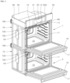
- the exterior of the first unit 1 is formed by a main body 10.
- the main body 10 may be formed into a shape including an approximately rectangular cuboid shape.
- the main body 10 may be made of a material having predetermined strength, to protect a plurality of components installed in the inner space of the main body 10.
- the main body 10 may include a cavity 11 forming its skeleton, and a front panel 12 being disposed at the front of the cavity 11 and forming the front surface of the main body 10.
- the cavity 11 has a cooking space 15 therein, and an open portion may be formed inside the front panel 12, and opens the cooking space 15 forward.
- the main body 10 may have a first accommodation space therein.
- the appliance is a cooking appliance, for example.
- the first accommodation space formed in the main body 10 may be a cooking space 15 needed to cook food items.
- the structure of the appliance is described under the assumption that the first accommodation space is the cooking space 15.
- the cooking appliance may be provided with a heating part that heats the cooking space 15.
- a convection part 18 may be provided at the rear side of the cooking space 15, and heats the inner space of the cooking space 15 as a result of convention of hot air.
- a control panel 20 may be disposed in the upper portion of the front surface of the appliance, i.e., on the front surface of the upper portion of the cavity 11.
- the control panel 20 may form a portion of the exterior of the front surface of the appliance.
- a display part may be disposed on the control panel 20.
- the display part may include an input part 21 that is used for adjusting the operations of the appliance, and a display 22 that displays the operation state of the appliance.
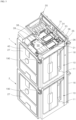
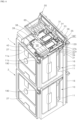
- a second accommodation space may be provided outside the cavity 11, specifically, in the upper portion of the cavity 11.
- the second accommodation space may be respectively provided in the upper portion of the cavity 11 in the first unit 1, and in the upper portion of the cavity 11 in the second unit 2.
- the suction opening 13 may be biased toward the end portion of one side of the front panel 12 in the left-right direction thereof from the left-to-right center of the front panel 12.
- the suction opening 13 may be disposed from the left-to-right center of the front panel 12 to the right side of the front panel 12.
- the upper surface of the cavity 11 may include a first area 11a and a second area 11b.
- the support plate 36 may be coupled to the front panel 12 disposed in front of the support plate 36.
- a portion of the upper end of the front panel 12 may bend and form a coupling surface parallel with the support plate 36, and a portion of the support plate 36 may protrude toward the front panel 12 and be coupled to the coupling surface of the front panel 12.
- the rear plate 38 may be disposed between a below-described fan 40 and the circuit board 31.
- the rear plate 38 may form a blocking wall that blocks between the fan 40 and the circuit board 31.
- the cold air having flown into the cold air flow path 50 may cool electronic components such as a circuit board 31 supported by the component supporter 35, and escape from the cold air flow path 50 through the exhaust opening 39 and flow into the fan 40.
- an opening part 14 may be formed on the front panel 12, and provides a passage for allowing the water tank 65 to pass through the front panel 12 in the front-rear direction.
- the opening part 14 may be biased toward the end portion of the other side of the front panel 12 in the left-right direction thereof from the left-to-right center of the front panel 12.
- the suction opening 13 may be biased toward the right side of the front panel 12, and the opening part 14 may be biased toward the left side of the front panel 12.
- the first sensing module 100 may be provided to sense vibrations caused by a knock input to the door 16. As the first sensing module 100 senses vibrations caused by a knock, the first sensing module 100 may operate in a way that outputs a first signal.
- the senor 110 in the embodiment may accurately distinguish vibrations caused by a knock that is input by the user from vibrations caused by another factor.
- the sensor 110 may sense vibrations, which are transferred in a pattern identical with a pattern unique to vibrations caused by a knock, as vibrations caused by the user's knock.
- the second sensing module 80 may be installed in the main body 10. At least a portion of the second sensing module 80 may be exposed toward the door 16 from the main body 10. In the embodiment, a portion of the second sensing module 80 is disposed on the front panel 12 in a way that penetrates in the front-rear direction, for example. Description in relation to this is provided hereafter.
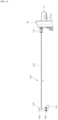
- the first sensing module 100 may include an input member, a transfer member 130, a sensor 110 and a support assembly 150.
- the input member may be provided to receive vibrations of the door 16.
- the input member may include an input switch 120.
- the input switch 120 may be disposed at the frontmost side of the first sensing module 100.
- the front panel 12 may have a suction opening 13 and an opening part 14, and the suction opening 13 may be biased toward the end portion of one side of the front panel 12 in the left-right direction of thereof.
- the input switch 120 may be disposed between the end portion of one side of the front panel 12 in the left-right direction thereof and the suction opening 13.
- the second accommodation space may be used as a component room 15. Accordingly, the transfer member 130 provided in the first unit 1 may connect between the input switch 120 and the sensor 110 while passing through a component room 30 where electronic components connecting to the controller 200 are disposed.
- the pattern of the vibration sensing signal caused by a knock may be determined previously.
- the sensor 110 may compare the pattern of an actually sensed vibration sensing signal with the pattern of the predetermined knock signal, and based on results of the comparison, determine whether vibrations are caused by a knock.
- the three axes sensor module 111 may include a single three axes acceleration sensor that senses vibrations, transferred in three axes directions orthogonal to one another, at the same time.
- the three axes acceleration sensor may detect three axes components of acceleration with a single sensor.
- the three axes acceleration sensor may detect a very small change in the movement (acceleration) of a medium in the three axes directions orthogonal to one another, which is caused by vibrations, respectively.
- the three axes sensor module 111 may include three independent acceleration sensors. In another example, the three axes sensor module 111 may include four or more independent acceleration sensors. As the number of acceleration sensors increases, accuracy in the sensor 110 's sensing of vibrations may improve.
- the senor 110 may further include a filter part 115.
- a vibration sensing signal sensed by the sensor 110 may include unnecessary noise in addition to a vibration sensing signal caused by a knock input.
- the filter part 115 may remove the noise.
- a knock is applied in the form of "knock knock", and vibrations corresponding to "knock knock” are indicated as a signal having magnitude greater than that of vibrations caused by another factor. Accordingly, when a vibration sensing signal corresponding to "knock knock is respectively at the magnitude of the first threshold and the second threshold or greater, the sensor micom 113 may determine that vibrations sensed by the sensor 110 are vibrations caused by a knock.
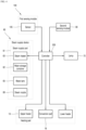
- the controller 200 may turn on/off the lamp 70, based on the signal.
- the sensor 110 Since the sensor 110 is formed into an integrated module, the sensor 110 may be easily installed, and the position of the installation of the sensor 110 may vary.
- the sensor 110 may be easily disposed at a supporter 160 of the support assembly 150 that is described hereafter. Description in relation to this is provided hereafter.
- FIG. 12 is an enlarged view showing portion "XII" of FIG. 6
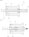
- FIG. 13 is a cross-sectional view showing the inner structure of an input switch of one embodiment
- FIG. 14 is a cross-sectional view showing the input switch of FIG. 13 is pressed.
- the input switch 120 may be disposed on the front panel 12, and at least a portion of the input switch 120 may be disposed between the front panel 12 and the door 16 and exposed toward the door 16.
- the input switch 120 may include a switch holder 121, and a moving member123.
- the switch holder 121 may form the exterior of the input switch 120, and have an accommodation space for accommodating the moving member 123 therein.
- the switch holder 121 is formed into a lying cylinder, for example.
- the switch holder 121 has a hollow hole therein, and the end portion of the front of the switch holder 121 may be open forward.
- the switch holder 121 may be disposed on the front panel 12. At this time, the open end portion of the front of the switch holder 121 may be exposed toward the front of the front panel 12, and most of the area of the switch holder 121 except for the open end portion of the switch holder 121 may be disposed in an area of the rear of the front panel 12, i.e., in the second accommodation space or the component room 30.
- the input switch 120 may further include a first elastic member 125.
- the first elastic member 125 may be provided to elastically support the moving member 123 at the rear of the moving member 123.
- the end portion of the front of the first elastic member 125 in the form of a coil spring may be coupled to the moving member 123.
- the end portion of the rear of the first elastic member 125 may be supported by the support cover 127.
- the input switch 120 may further include a coupling member 129.
- the coupling member 129 may be provided to couple the support cover 127 to the switch holder 121.
- the switch holder 121 is formed into a lying cylinder, both sides of which are open in the front-rear direction, and the support cover 127 covers the open end portion of the rear of the switch holder 121, for example.
- the coupling member 129 may couple the support cover 127 to the switch holder 121 such that the support cover 127 does not separate from the switch holder 121.
- the input switch 120 may be disposed in a position appropriate enough to receive vibrations caused by a knock input to the door 16. That is, the input switch 120 may be disposed in a position of the main body 10, closest to the door 16 onto which a knock input is applied, while being installed in the main body 10.
- the rear support surface is a surface that supports the PCB substrate, between the PCB substrate on which the sensor 110 is mounted and the transfer member 130.
- the rear support surface 162 may have a flat surface shape corresponding to the flat surface shape of the PCB substrate.
- the PCB substrate and the rear support surface 162 may be respectively formed into a rectangular flat surface.
- the PCB substrate on which the sensor 110 is mounted may be coupled to the sensor support part 161 while closely contacting the rear support surface 162.
- the side wall 163a, 163b, 163c may be disposed at each of the edges of the rear support surface 162.
- the side walls 163a, 163b, 163c may surround the rear support surface 162 outside the rear support surface 162, e.g., from the outside in the up-down direction and the left-right direction.
- the sensor support part 161 may further include a fastening projection 164a, 164b.
- the fastening projection 164a, 164b may protrude from the side wall.
- the PCB substrate may be detachably coupled to the sensor support part 161 while being fitted between the rear support surface 162 and the fastening projection 164a, 164b.
- the first fastening projection 164a may protrude from a lower side wall 163a disposed at the lower end of the sensor support part 161, among the side walls 163a, 163b, 163c.
- the first fastening projection 164a may be spaced a predetermined distance apart from the rear support surface 162 and protrude from the lower side wall 163a.
- the second fastening projection 164b may protrude in the form of a hook from an upper side wall 163b disposed at the upper end of the sensor support part 161, among the side walls 163a, 163b, 163c.
- the second fastening projection 164b may be spaced a predetermined distance apart from the rear support surface 162, and protrude from the upper side wall 163b.
- the cut surface may be elastically deformed in the up-down direction with respect to the end portion of the front of the cut surface, adj acent to the rear support surface 162.
- the cut surface may serve as a body that supports the second fastening projection 164b. That is, the cut surface may be provided in the form of a hook body that forms a hook member together with the second fastening projection 164b formed into a hook projection.
- the PCB substrate fitted between the rear support surface 162 and the second fastening projection 164b may separate from the supporter in the state in which the second fastening projection 164b bends upward.
- the sensor support part 161 may further include a contact surface 160b.
- the contact surface 160b may be provided as a surface that contacts the transfer member 130 on the opposite side of the rear support surface 162.
- the contact surface 160b may be the back surface of the rear support surface 162 provided on the same member as the contact surface 160b. That is, on a single member constituting the supporter 160, the contact surface 160b may form the front surface of the member, and the rear support surface 162 may form the rear surface of the member.
- the supporter 160 may further include an extension part 163e.
- the extension part 163e may extend forward from the upper side wall 163b. Because of the extension part 163e, the upper side wall 163b may protrude further rearward than the rear support surface 162. In other words, the upper side wall 163b may protrude further rearward than the other side walls 163a, 163c by the length of the extension part 163e.
- the width of the up-to-down deformation of the hook member specifically, the width of the up-to-down movement of the second fastening projection 164b may further increase. Accordingly, since the hook member, and the second fastening projection 164b forming the hook member may bend further upward, the PCB substrate may be attached and detached more readily and reliably.
- the support leg 166a, 166b may protrude from the rear support surface 162 rearward and downward.
- the support leg 166a, 166b includes a first leg part 166a and a second leg part 166b, for example.
- the first leg part 166a may protrude from the lower end of the rear support surface 162 downward.
- the second leg part 166b may extend from the lower end of the first leg part 166a rearward.
- first leg part 166a and the second leg part 166b connect to each other in the form of "L", for example.
- the first leg part 166a may extend from the sensor support part 161 toward the supporter holder 170.
- the second leg part 166b may form a flat surface approximately parallel with the upper surface of the supporter holder 170, specifically, the flat surface formed by a support surface 172 that is described hereafter.
- the pair of rotation projections 167 may protrude respectively from one side and the other side of the support leg 166a, 166b in the left-right direction.
- Each of the rotation projections 167 may be rotatably coupled to the supporter holder 170.
- each of the rotation projections 167 may be rotatably coupled to the supporter holder 170, specifically, a rotation projection supporter 175 that is described hereafter, in the front-rear direction.
- the rotation support part 165 may further include a side support surface 168.
- the side support surface 168 may be formed into a flat surface that connects the rear support surface 162 or the contact surface 160b with the support leg 166a, 166b at both sides of the rear support surface 162 or the contact surface 160b in the left-right direction.
- the side support surface 168 may formed into a flat surface that connects to the rear support surface 162 or the contact surface 160b and the first leg part 166a and the second leg part 166b.
- the upper end of the side support surface 168 may connect to the rear support surface 162 or the contact surface 160b.
- the rear end of the side support surface 168 may connect to the rear support surface 162 or the contact surface 160b and the first leg part 166a.
- the lower end of the side support surface 168 may connect to the second leg part 166b.
- the side support surface 168 as described above, may connect to the rear support surface 162 or the contact surface 160b and the support leg 166a, 166b. When viewed from the side, the side support surface 168 may be formed into an approximate triangle.
- the side support surface 168 may help to suppress the occurrence of the bend of the support leg 166a, 166b, in particular, the second leg part 166b.
- the side support surface 168 may support the second leg part 166b at both sides, to prevent the bend of the second leg part 166b caused by the external force.
- the side support surface 168 may limit a range of the left-to-right movement of the transfer member 130 such that the transfer member 130 contacting the contact surface 160b does not escape from the contact surface 160b in the left-right direction of the contact surface 160b.
- the rotation support part 165 may further include a side rib 169.
- the side rib 169 may protrude from the contact surface 160b forward.
- the rotation support part 165 may include a plurality of side ribs 169. Each of the side ribs 169 may be formed in a way that extends transversely.
- the side rib 169 is a protruding structure formed on the supporter 160 and helps to improve the strength of the supporter 160.
- the side rib 169 may be disposed under the area where the contact surface 160b and the transfer member 130 usually contact each other.
- the side rib 169 may support the transfer member 130 from below.
- the side rib 169 may prevent the transfer member 130 from being pushed excessively downward on the contact surface 160b in the process in which the transfer member 130 pushes the supporter 160 while contacting the contact surface 160b.
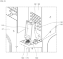
- the holder main body 171 may form the skeleton of the supporter 160 and be coupled to the rear of the cavity 11.
- the holder main body 171 may be disposed under the supporter 160.
- the holder main body 171 may be provided with a coupling surface 173.
- the coupling surface 173 is a portion that is used to couple the supporter holder 160 to the rear surface of the cavity 11.
- the coupling surface 173 may be formed into a flat surface disposed on the front surface of the holder main body 171.
- the second elastic member 180 may keep the supporter 160 biased forward toward the door 16. At this time, the upper end f the supporter 160 may be kept biased further forward than the lower end of the supporter 160 adjacent to the rotation center of the supporter 160.
- the second elastic member 180 may be provided in the form of a coil spring.
- the upper end of the second elastic member 180 in the form of a coil spring may be coupled to the supporter 160, and the lower end of the second elastic member 180 may be coupled to the supporter holder 170.
- the second elastic member 180 in the form of a coil spring may be spaced rearward from the rotation center of the supporter 160. That is, the second elastic member 180 may be spaced rearward from the rotation projection 167. For example, the second elastic member 180 may be biased toward the end portion of the rear of the supporter 160.
- the supporter holder 170 may further include a first spring support part 177, and the sensor support part 161 may further include a second spring support part 160a.
- the supporter 160 may rotate in the front-rear direction, and the second elastic member 180 may be pressed or extend in the up-down direction.
- the second elastic member 180 may be provided in the form of a coil spring having a circular truncated cone shape the diameter of which increases toward its lower portion.
- the second elastic member 180 formed into a circular truncated cone-shaped coil spring may suppress the problem that occurs when the upper lateral surface and the lower lateral surface of the second elastic member 180 are jammed and caught mutually while contacting each other in the process of repetitive rotation of the supporter 160, and the like.
- the first distance is defined as a gap between the second leg part 166b and the upper rib 174 when the second leg part 166b and the upper rib 174 are disposed in parallel.
- the second leg part 166b and the upper rib 174 are spaced by the first distance, the second leg part 166b does not contact the upper rib 174.
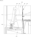
- the supporter 160 rotates rearward by a first rotation angle or rotates forward by a second rotation angle, the rearward rotation or the forward rotation of the supporter 160 may be limited, while the second leg part 166b interferes with the holder main body 171, i.e., the upper rib 174.
- the first rotation angle may be properly determined depending on a limited range of the rearward rotation of the supporter 160, and the second rotation angle may be properly determined depending on a limited range of the forward rotation of the supporter 160, which will be limited. Additionally, the first distance may be properly determined within the range where the rotation of the supporter 160 is limited by the first rotation angle and the second rotation angle.
- FIG. 24 is a lateral cross-sectional view showing another example of the support assembly in FIG. 15
- FIG. 25 is a bottom view showing the bottom surface of the supporter holder in FIG. 24
- FIG. 26 is a lateral cross-sectional view showing the posture of the supporter in FIG. 24 changes.
- FIGS. 24 to 26 show another example of the support assembly 1500.
- a second elastic member 1770 may be spaced a predetermined distance apart from the rotation center of a supporter 1600, and extend from the holder main body 171 to protrude to the upper portion of the holder main body 171.
- the second elastic member 1770 may be formed into a projection that is elastically deformed in the up-down direction with respect to the portion where the second elastic member 1770 and the holder main body 171 connect.
- the second elastic member 180 may be formed in a way that a portion of the support surface 172 of the holder main body 171 is cut and that a portion of the cut support surface 172 is deformed to protrude to the upper portion of the holder main body 171.
- one of the front or the rear of the second elastic member 1770 may connect to the support surface 172, and the remaining portions may be formed in a way that separates from the support surface 172.
- the front and both the lateral surfaces the second elastic member 1770 separate from the support surface 172, and a portion of the rear may only be formed into a projection connecting to the support surface 172.
- the second elastic member 180 may be formed to bend upward from the portion where the second elastic member 1770 connects to the support surface 172, such that at least a portion of the second elastic member 1770 protrudes to the upper portion of the holder main body 171.
- the second elastic member 1770 may be formed into a projection that is elastically deformed in the up-down direction with respect to the portion where the second elastic member 1770 connects to the holder main body 171, i.e., the support surface 172.
- the second elastic member 180 may elastically support the supporter 1600 in the position where the second elastic member 180 is spaced rearward from the rotation center of the supporter 1600.
- a coil spring does not need to be additionally installed to support the supporter 1600. Accordingly, structures for installing a coil spring such as a first spring support part 175 (see FIG. 16 ) and a second spring support part 160a (see FIG. 16 ) do not need to be added to the supporter 1600 and the supporter holder 1700.
- FIG. 27 is a view showing a first sensing module with a door open
- FIG. 28 is a view showing a transfer member starts to contact a supporter while a door is closed
- FIG. 29 is a view showing a first sensing module with a door closed
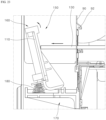
- FIG. 30 is a view showing a first sensing module at a time of a knock operation.
- the first sensing module 100 may include a sensor 110, an input switch 120, a transfer member 130 and a support assembly 150.
- the support assembly 150 may be disposed at the rear of the cavity 11, and the sensor 110 may be supported by the support assembly 150 and disposed at the rear of the cavity 11.
- the input switch 120 may be disposed at the front of the cavity 11.
- the input switch 120 may be disposed on the front panel 12, and at least a portion of the input switch 120 may be disposed between the front panel 12 and the door 16 and exposed toward the door 16.
- the transfer member 130 may connect between the input switch 120 and the sensor 110.
- the transfer member 130 may connect to the input switch 120, at the front of the cavity 11, and connect to the supporter 160, at the front of the cavity 11.
- the moving member 123 may move rearward while being slightly pressed by the door 16 as the door 16 closes a cooking space 15 (see FIG. 2 ).
- the transfer member 130 may move rearward together with the moving member 123.
- the transfer member 130 may move to a position where the transfer member 130 contacts the supporter 160.
- the elastic force provided by the second elastic member 180 may keep the supporter 160 contacting the transfer member 130 reliably.
- the transfer member 130 is formed into a rod, for example.
- the transfer member 130 may be formed into a rod having a rigid body that does not bring about vibration damping.
- the transfer member 130 is formed into a rod having a rigid body, the supporter 160 may be kept contacting the rod 130 reliably.
- the supporter 160 may rotate rearward, and the sensor 110 may move rearward together with the supporter 160 rotating rearward. In this process, the sensor 110 may sense vibrations transferred to the supporter 160.
- the transfer member 130 is formed into a rod having a rigid body as described above, the supporter 160 and the rod 130 may be kept contacting each other reliably.
- the input switch 120 is turned on, and the input switch 120 and the sensor 110 electrically connect to each other.
- the input switch 120 is turned off, and the input switch 120 and the sensor 110 electrically disconnect from each other.
- a transfer member 130 in the form of an electric wire, and a transfer member 130 in the form of a rod may be provided together.
- the operation of the sensor 110 may be determined by the transfer member 130 in the form of an electric wire, and vibrations may be transferred to the supporter 160 by the transfer member 130 in the form of a rod.
- the controller 200 may control the operation of the lamp 70, based on the first signal.
- a lamp button displayed on the input part 21 of the display part is used to manually turn on/off the lamp 70 regardless of the user's knock motion. That is, as the user touches the lamp button displayed on the input part 21 of the display part once, the lamp 70 is turned on, and as the user touches the lamp button once again, the lamp 70 is turned off.
- the lamp 70 In the state in which the lamp 70 is on at the touch of the lamp button, the lamp 70 is not turned off even if a knock is input. That is, in the state in which the lamp 70 is on as the user touches the lamp button manually, the knock-on function is not performed.
- a self-cleaning button may be displayed on the input part 22 of the display part.
- Self-cleaning may involve automatically sterilizing and cleaning the cooking space 15 itself, and the like.
- the operation of the appliance may be set such that the knock-on function cannot be performed. At this time, despite the user's knock motion, the lamp 70 is not turned on/off.
- the temperature of the cooking space 15 remains very high.
- the lamp 70 is turned on in this state, the lamp 70 is likely to be broken due to high-temperature heat.
- the operation of the appliance may be set such that knock-on function cannot be performed during the self-cleaning procedure.
- the appliance in the embodiment may use the first sensing module 100 provided with the sensor 110 sensing vibrations, to sense whether the door 16 is closed mechanically, without an additional module.
- the first accommodation space is disposed at the inside of the main body 10 in the left-right direction and at the inside of the main body 10 in the up-down direction.
- the first sensing module 100 in the embodiment may be installed in the main body 10 in a way that the first sensing module 100 is disposed in the first accommodation space, i.e., outside the cooking space 15.
- the first sensing module 100 may be disposed at the edge of the right side of the main body 10 in a way that the first sensing module 100 is biased toward the upper side and the right side of the cooking space 15.
- the input switch 120 disposed at the frontmost side of the first sensing module 100 may be disposed on the front panel 12.
- the input switch 120 may be disposed at the edge of the right side of the front panel 12.
- the fan 40 is biased toward one side of the main body 10 in the left-right direction thereof. Accordingly, the suction opening 13 may be disposed from the left-to-right center of the front panel 12 to one side of the font surface panel 12 in the left-right direction thereof.
- the suction opening 13 and the fan 40 need to be disposed at the right side of the main body 10.
- the input switch 120 of the first sensing module 100 and the second sensing module 80 may be disposed very close to the end portion of the right side of the front panel 12 and the end portion of the left side of the front panel 12, respectively.
- the height of the component room 30 and the height of the first accommodation space decreases.
- the up-to-down width of the second accommodation space of the second unit 2 is much less than that of the second accommodation space of the first unit 1, in the embodiment.
- the amount of external air flowing into the second accommodation space of the second unit 2 needs to increase. Accordingly, in the second unit 2, most of the area of the front panel 12 is occupied by the suction opening 13.
- the transfer member 130 connecting to the input switch 120 may pass through the second accommodation space and connect to the sensor 110.
- the transfer member 130 may be disposed to pass through the component room 30.
- the transfer member 130 may be disposed outside the area where electronic components are disposed, in the left-right direction.
- the transfer member 130 since the transfer member 130 is disposed as described above, the above-mentioned problems may be prevented, and vibrations transferred to the input switch 120 may be reliably transferred to the sensor 110 by the transfer member130.
- the cavity 11 may include a heater accommodation part that is depressed upward from the upper surface of the cavity 11. When viewed from the inside of the cooking space 15, the heater accommodation part may be depressed upward from the upper surface of the cavity 11.
- the heater accommodation part may accommodate at least a portion of the heating part, i.e., the upper heater 19.
- the outside of the cooking space 15, i.e., the heater accommodation part, when viewed from the second accommodation space, may be formed convexly from the upper surface of the cavity 11 toward the second accommodation space, i.e., in the upward direction.
- the transfer member 130 may be disposed outside the heater accommodation part in the left-right direction thereof, while being disposed in the second accommodation space.
- the heater accommodation part corresponds to the first area 11a on the upper surface of the cavity 11.
- the upper heater 19 is disposed under the first area 11a, and electronic components are disposed on the first area 11a.
- electronic components such as a circuit board 31 may be disposed in the component room 30 in a way that the electronic components are spaced a predetermined distance from the cavity 11, while being supported by the component supporter 35.
- the transfer member 130 may connect between the input switch 120 and the sensor 110 while passing through a space between the end portion of the right side of the cavity 11 and the heater accommodation part, in the front-rear direction, in the second accommodation space.
- the alignment of the positions of the input switch 120 and the door 16 for a smooth contact between the input switch 120 and the door 16 may hardly be ensured. Additionally, for the installation of the input switch 120, the up-to-down length of the front panel 12 needs to increase.
- the transfer member 130 when the transfer member 130 is disposed in the first area 11a, the position of the input switch 120 and the position of the suction opening 13 overlap on the front panel 12. At this time, the entire surface area of the suction opening 13 is reduced by the input switch 120, and the cooling effect on the second accommodation space may deteriorate. Additionally, since the input switch 120 is disposed in the area where the suction opening 13 is disposed, the aesthetic qualities of the appliance may deteriorate.
- the first area 11a is an area where electronic components are disposed. If the transfer member 130 is disposed in the first area 11a, the first area 11a becomes so complex due to large number of components, the transfer member 130 and the electronic components interfere with one another, and the electronic components are highly likely to be broken by the transfer member 130.
- the transfer member 130 in the embodiment is disposed outside the first area 11a, i.e., the heater accommodation part, without being disposed in the first area 11a. That is, the transfer member 130 in the embodiment may connect between the input switch 120 and the sensor 110 while passing through the space between the end portion of the right side of the cavity 11 and the heater accommodation part in the front-rear direction.
- the transfer member 130 in the embodiment is disposed as described above, the above-mentioned problems may be prevented. Additionally, since the transfer member 130 is disposed as described above, the effect of heat generated by the heating part on the transfer member 130 may be effectively suppressed.
- the transfer member 130 when the transfer member 130 is disposed near the heating part, the transfer member 130 may be deformed due to heat generated by the heating part. At this time, the transfer member 130 may not connect between the input switch 120 and the sensor 110 properly, and accordingly, vibrations may not be properly transferred to the sensor 110.
- the fan 40 is biased toward the rear in the second accommodation space, for example.
- the fan 40 may create the flow of air flowing to the front of the second accommodation space to the rear of the second accommodation space.
- a duct cover 27 may be disposed at the rear of the cavity 11 and below the fan 40.
- the fan 40 may allow external air to flow into the second accommodation space through the suction opening 13.
- the fan 40 may suction the air having flown into the second accommodation space and discharge the air to a space in the duct cover 27.
- the fan 40 may suction air through its front, and discharge the suctioned air to its lower portion. If the fan 40 is biased toward the front in the second accommodation space, i.e., disposed near the front panel 12, air may not be discharged properly through the duct cover 27.
- the fan 40 is disposed at the front side of the appliance, since the fan 40 is too close to the user, the noise of the fan 40 may cause inconvenience to the user.
- the fan 40 in the embodiment is biased toward the rear in the second accommodation space.
- the sensor 110 in the embodiment is also disposed near the fan 40, i.e., at the rear of the cavity 11.
- the transfer member 130 may protrude to the rear of the cavity 11 while passing through the cover bracket 90, and to this end, a rod penetration hole 94 may be formed at the cover bracket 90 in a way that penetrates in the front-rear direction.
- the transfer member 130 may be installed in the appliance without being affected by or affecting the electronic components in the appliance.
- the appliance in the embodiment can sense a knock input effectively without being affected by or affecting the electronic components installed in the appliance.
- FIG. 31 is a front view showing the appliance of FIG. 2 without a door in another embodiment.
- FIG. 32 is a flowchart for describing a control method of an appliance in one embodiment.
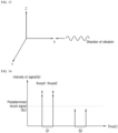
- FIG. 33 is a view showing the direction of one axis of a three axes sensor module and the direction of vibrations caused by a knock, in one embodiment.
- FIG. 34 is a view showing a vibration sensing signal caused by a knock in the appliance of one embodiment.
- FIGS. 35 and 36 are views showing a vibration sensing signal generated in each unit of the appliance of one embodiment.
- the vibrations transferred to the sensor 110 may include unnecessary noise in addition to the vibration sensing signal caused by the knock input.
- the appliance in the embodiment may remove the unnecessary noise from the vibrations transferred to the sensor 110, by using the filter part 115.
- the vibration sensing signal may pass through the filter part 115 as described, be amplified by the amplification part 117 and then be input to the sensor micom 113.
- the sensor micom 113 may determine that a knock is given, when the predetermined knock signal Sc is sensed as "knock 1" and “knock 2" continuously at predetermined intervals.
- the sensor micom 113 may determine that vibrations are not caused by a knock, and transmit a signal corresponding to the determination to the controller 200.
- the sensor micom 113 may determine that vibrations sensed by the sensor 110 are not caused by a knock when a maximum value of the vibration sensing signal in at least one of the y-axis or z-axis direction is greater than a maximum value of the vibration sensing signal in the x-axis direction.
- a knock input may be usually performed through the see-through window 16a attached on the door 16 of the appliance. Vibrations caused by the knock may be transferred to the input switch 120 disposed on the front panel 12, and transferred to the sensor 110 through the transfer member 130 connecting to the input switch 120. That is, vibrations caused by a knock input occur only in one direction of the x-axis.
- the sensor micom 113 may determine that vibrations sensed by the sensor 110 are vibrations caused by a knock only when a maximum value of the intensity of the vibration sensing signal in the x-axis direction is greater than a maximum value of the intensity of the vibration sensing signal in the y-axis direction, a maximum value of the intensity of the vibration sensing signal in the z-axis direction, and the predetermined knock signal Sc.
- the sensor micom 113 may be set to determine that vibrations sensed by the sensor 110 are not caused by a knock when the maximum value of the intensity of the vibration sensing signal in at least one of the y-axis or z-axis direction is greater than the maximum value of the intensity of the vibration sensing signal in the x-axis direction.
- the senor 110 in the embodiment may accurately distinguish a first knock-on/off signal corresponding to a knock input by the user to the first unit 1 from a second knock-on/off signal corresponding to a knock input by the user to the second unit 2.
- the intensity of vibrations caused by a knock input by the user may be determined depending on the position of a portion to which the knock is input.
- vibrations caused by the knock are sensed as a first vibration sensing signal S3 of large magnitude by the sensor micom 113 disposed at the rear of the first unit 1, and sensed as a second vibration sensing signal S4 of less magnitude than that of the first vibration sensing signal S3 by the sensor micom 113 disposed at the rear of the second unit 2.
- vibrations transferred to the input switch 120 disposed on the front panel 12 of the first unit 1, may be transferred directly to the sensor 110 through the transfer member 130, and a first vibration sensing signal S3 of large magnitude may be input to the sensor micom 113 of the first unit 1.
- a second vibration sensing signal S4 input to the sensor micom 113 of the second unit 2 may have less intensity than the first vibration sensing signal S3 by magnitude 'I'.
- a vibration sensing signal S4 may have less intensity than the first vibration sensing signal S3 by magnitude 'I'.
- the vibration absorption member 3 including a material capable of absorbing vibrations may be disposed between the first unit 1 and the second unit 2 that are made of a metallic material and transfer vibrations well.
- the vibration absorption member 3 may reduce interference between the units, caused by vibrations.
- the vibration absorption member 3 may be made of a material such as rubber or sponge and the like capable of absorbing vibrations but not limited.
- both of the first vibration sensing signal S3 and the second vibration sensing signal S4 are determined as vibrations caused by a knock, both of the first vibration sensing signal S3 and the second vibration sensing signal S4 have intensity that is the intensity or greater of the predetermined knock signal Sc.
- the sensor micom 113 may determine the first and second sensing signals S3, S4, based on a signal output by the amplification part 117.
- the sensor micom 113 may determine the first vibration sensing signal S3 having greater intensity than the second vibration sensing signal S4 as a first knock-on/off signal corresponding to a knock input by the user, and transfer an output signal to the controller 200. In other words, the sensor micom 113 may determine the first vibration sensing signal as the first knock-on/off signal indicating that the user inputs a knock to the first unit 1.
- the controller 200 As the sensor micom 113 determines that the first knock-on/off signal has occurred in the first unit 1, the controller 200 ascertains the on/off state of the lamp 70 of the first unit 1 (S160). Then the controller 200 may turn on/off the lamp 70 (S170, S180).
- the controller 200 when determining the first knock-on/off signal in the state in which the lamp 70 is off, the controller 200 outputs an on output signal to the lamp 70. Then the controller 200 may turn on the lamp 70 of the first unit 1, based on the on output signal (S170).
- the controller 200 when determining the first knock-on/off signal in the state in which the lamp 70 is on, the controller 200 outputs an off output signal to the lamp 70. Then the controller 200 may turn off the lamp 70 of the first unit 1, based on the off output signal (S180).
- the controller 200 When determining the first knock-on/off signal of the first unit 1, the controller 200 ignores the second vibration sensing signal S4 sensed by the sensor micom 113 of the second unit 2 at the same time as the controller 200 determines the first vibration sensing signal S3 as the first knock-on/off signal (S190).
- a time interval between a knock and a knock is less than one second, and in an example, the time interval may be 500 ms to 600 ms.
- the sensor micom 113 may set time as much as the time interval between a knock and a knock such that the second vibration sensing signal S4 sensed by the second unit 2 is ignored.
- vibrations caused by the knock may be sensed as a third vibration sensing signal S6 of large magnitude by the sensor micom 113 disposed at the rear of the second unit 2, and sensed as a fourth vibration sensing signal S5 having less magnitude than the third vibration sensing signal S6 by the sensor micom 113 disposed at the rear of the first unit 1.
- the first unit 1 When the first unit 1 is not limited in the state where the position of the occurrence of the second knock-on/off signal corresponding to a knock input by the user is determined as the second unit 2, an output signal may also be applied to the lamp 70 of the first unit 1. Then the on/off operation may also be performed to the first unit 1, and an operational error such as a simultaneous turn-on or turn-off of the lamp 70 in the first accommodation space of each of the first unit 1 and the second unit 2 may occur. To prevent the operational error, the fourth vibration sensing signal S5 sensed by the sensor micom 113 of the first unit 1 is ignored to prevent an on/off output signal from be applied to the lamp 70 of the first unit 2.
Landscapes
- Engineering & Computer Science (AREA)
- Chemical & Material Sciences (AREA)
- Combustion & Propulsion (AREA)
- Mechanical Engineering (AREA)
- General Engineering & Computer Science (AREA)
- Physics & Mathematics (AREA)
- General Physics & Mathematics (AREA)
- Thermal Sciences (AREA)
- Electric Ovens (AREA)
Applications Claiming Priority (2)
| Application Number | Priority Date | Filing Date | Title |
|---|---|---|---|
| KR1020210106321A KR20230024152A (ko) | 2021-08-11 | 2021-08-11 | 가전기기 |
| EP22189711.9A EP4134608B1 (de) | 2021-08-11 | 2022-08-10 | Gerät |
Related Parent Applications (2)
| Application Number | Title | Priority Date | Filing Date |
|---|---|---|---|
| EP22189711.9A Division EP4134608B1 (de) | 2021-08-11 | 2022-08-10 | Gerät |
| EP22189711.9A Division-Into EP4134608B1 (de) | 2021-08-11 | 2022-08-10 | Gerät |
Publications (2)
| Publication Number | Publication Date |
|---|---|
| EP4534936A2 true EP4534936A2 (de) | 2025-04-09 |
| EP4534936A3 EP4534936A3 (de) | 2025-06-11 |
Family
ID=82899287
Family Applications (2)
| Application Number | Title | Priority Date | Filing Date |
|---|---|---|---|
| EP25159352.1A Pending EP4534936A3 (de) | 2021-08-11 | 2022-08-10 | Gerät |
| EP22189711.9A Active EP4134608B1 (de) | 2021-08-11 | 2022-08-10 | Gerät |
Family Applications After (1)
| Application Number | Title | Priority Date | Filing Date |
|---|---|---|---|
| EP22189711.9A Active EP4134608B1 (de) | 2021-08-11 | 2022-08-10 | Gerät |
Country Status (3)
| Country | Link |
|---|---|
| US (2) | US12449134B2 (de) |
| EP (2) | EP4534936A3 (de) |
| KR (1) | KR20230024152A (de) |
Citations (3)
| Publication number | Priority date | Publication date | Assignee | Title |
|---|---|---|---|---|
| JP2018094416A (ja) | 2016-12-14 | 2018-06-21 | パナソニックIpマネジメント株式会社 | 食器洗い機 |
| WO2021125430A1 (ko) | 2019-12-19 | 2021-06-24 | 엘지전자 주식회사 | 투시창이 설치된 가전기기 |
| KR20210095506A (ko) | 2020-01-23 | 2021-08-02 | 엘지전자 주식회사 | 투시창이 설치된 가전기기 |
Family Cites Families (17)
| Publication number | Priority date | Publication date | Assignee | Title |
|---|---|---|---|---|
| KR100747814B1 (ko) | 2004-12-27 | 2007-08-08 | 엘지전자 주식회사 | 오븐도어 개폐 감지장치 |
| SG11201701909PA (en) * | 2014-09-17 | 2017-04-27 | Tlv Co Ltd | Sensor device |
| DE102014114177A1 (de) | 2014-09-30 | 2016-03-31 | Miele & Cie. Kg | Haushaltsgerät mit zwei oder mehreren Geräteeinheiten |
| KR20160045545A (ko) * | 2014-10-17 | 2016-04-27 | 엘지전자 주식회사 | 냉장고 |
| KR101668921B1 (ko) | 2014-12-24 | 2016-10-24 | 엘지전자 주식회사 | 터치 센서 어셈블리 및 터치 센서 어셈블리가 구비된 냉장고 도어 |
| EP3098519A1 (de) * | 2015-05-26 | 2016-11-30 | Electrolux Appliances Aktiebolag | Tür und haushaltsgerät mit einer tür |
| KR101944996B1 (ko) | 2017-02-15 | 2019-02-11 | 김동연 | 대행서비스 제공 시스템, 서버 및 방법 |
| KR102359721B1 (ko) | 2017-06-28 | 2022-02-07 | 엘지전자 주식회사 | 노크 온 도어 및 이를 구비하는 조리기기 |
| ES2902801T3 (es) * | 2017-06-29 | 2022-03-29 | Tlv Co Ltd | Dispositivo sensor |
| US11965771B2 (en) | 2018-03-30 | 2024-04-23 | Whirlpool Corporation | Beverage refrigerator with system and methods for weight detection, inventory monitoring, and overload condition notification |
| KR102132485B1 (ko) | 2018-04-16 | 2020-07-09 | 엘지전자 주식회사 | 조리기기 |
| KR20200042263A (ko) | 2018-10-15 | 2020-04-23 | 엘지전자 주식회사 | 조리기기 및 조리기기의 도어 자동 개방 제어 방법 |
| KR102899399B1 (ko) * | 2019-12-06 | 2025-12-11 | 엘지전자 주식회사 | 식기세척기 |
| KR102613968B1 (ko) | 2019-12-19 | 2023-12-14 | 엘지전자 주식회사 | 가전기기 및 그의 제어방법 |
| CN212109183U (zh) | 2020-03-26 | 2020-12-08 | 佛山市云米电器科技有限公司 | 带敲击模块自动开门装置安装结构、自动开门装置、冰箱 |
| CN212058816U (zh) | 2020-04-03 | 2020-12-01 | 代傲阿扣基金两合公司 | 敲击检测装置和具有敲击检测装置的家用电器 |
| JP7684059B2 (ja) | 2020-04-08 | 2025-05-27 | モメンティブ・テクノロジーズ・山形株式会社 | 石英ガラスルツボの製造方法 |
-
2021
- 2021-08-11 KR KR1020210106321A patent/KR20230024152A/ko active Pending
-
2022
- 2022-08-10 EP EP25159352.1A patent/EP4534936A3/de active Pending
- 2022-08-10 US US17/884,945 patent/US12449134B2/en active Active
- 2022-08-10 EP EP22189711.9A patent/EP4134608B1/de active Active
-
2025
- 2025-09-23 US US19/337,102 patent/US20260016171A1/en active Pending
Patent Citations (3)
| Publication number | Priority date | Publication date | Assignee | Title |
|---|---|---|---|---|
| JP2018094416A (ja) | 2016-12-14 | 2018-06-21 | パナソニックIpマネジメント株式会社 | 食器洗い機 |
| WO2021125430A1 (ko) | 2019-12-19 | 2021-06-24 | 엘지전자 주식회사 | 투시창이 설치된 가전기기 |
| KR20210095506A (ko) | 2020-01-23 | 2021-08-02 | 엘지전자 주식회사 | 투시창이 설치된 가전기기 |
Also Published As
| Publication number | Publication date |
|---|---|
| US20230047429A1 (en) | 2023-02-16 |
| EP4134608A1 (de) | 2023-02-15 |
| KR20230024152A (ko) | 2023-02-20 |
| EP4134608B1 (de) | 2025-04-23 |
| EP4534936A3 (de) | 2025-06-11 |
| US20260016171A1 (en) | 2026-01-15 |
| US12449134B2 (en) | 2025-10-21 |
Similar Documents
| Publication | Publication Date | Title |
|---|---|---|
| US20250254773A1 (en) | Control method of appliance | |
| AU2020409316B2 (en) | Home appliance provided with viewing window | |
| US12253247B2 (en) | Home appliance and control method therefor | |
| US20260016169A1 (en) | Home appliance provided with viewing window | |
| EP4134590A1 (de) | Gerät | |
| EP4080119A1 (de) | Haushaltsgerät und steuerungsverfahren dafür | |
| US20250341315A1 (en) | Appliance | |
| EP4534936A2 (de) | Gerät | |
| EP4134591A1 (de) | Gerät mit einer tür und einem sensormodul zur erfassung eines klopfens an der tür | |
| KR20230174402A (ko) | 가전기기 | |
| US12607361B2 (en) | Appliance | |
| US20240099496A1 (en) | Water supply device, and steam supply device and cooking appliance comprising the same |
Legal Events
| Date | Code | Title | Description |
|---|---|---|---|
| PUAI | Public reference made under article 153(3) epc to a published international application that has entered the european phase |
Free format text: ORIGINAL CODE: 0009012 |
|
| STAA | Information on the status of an ep patent application or granted ep patent |
Free format text: STATUS: REQUEST FOR EXAMINATION WAS MADE |
|
| 17P | Request for examination filed |
Effective date: 20250221 |
|
| AC | Divisional application: reference to earlier application |
Ref document number: 4134608 Country of ref document: EP Kind code of ref document: P |
|
| AK | Designated contracting states |
Kind code of ref document: A2 Designated state(s): AL AT BE BG CH CY CZ DE DK EE ES FI FR GB GR HR HU IE IS IT LI LT LU LV MC MK MT NL NO PL PT RO RS SE SI SK SM TR |
|
| PUAL | Search report despatched |
Free format text: ORIGINAL CODE: 0009013 |
|
| AK | Designated contracting states |
Kind code of ref document: A3 Designated state(s): AL AT BE BG CH CY CZ DE DK EE ES FI FR GB GR HR HU IE IS IT LI LT LU LV MC MK MT NL NO PL PT RO RS SE SI SK SM TR |
|
| RIC1 | Information provided on ipc code assigned before grant |
Ipc: F25D 23/02 20060101ALI20250508BHEP Ipc: F24C 15/02 20060101ALI20250508BHEP Ipc: F24C 15/00 20060101ALI20250508BHEP Ipc: F24C 7/08 20060101ALI20250508BHEP Ipc: F25D 29/00 20060101AFI20250508BHEP |
|
| GRAP | Despatch of communication of intention to grant a patent |
Free format text: ORIGINAL CODE: EPIDOSNIGR1 |
|
| STAA | Information on the status of an ep patent application or granted ep patent |
Free format text: STATUS: GRANT OF PATENT IS INTENDED |