EP4534808A2 - Lageranordnung für einen gasturbinenmotor - Google Patents
Lageranordnung für einen gasturbinenmotor Download PDFInfo
- Publication number
- EP4534808A2 EP4534808A2 EP24205048.2A EP24205048A EP4534808A2 EP 4534808 A2 EP4534808 A2 EP 4534808A2 EP 24205048 A EP24205048 A EP 24205048A EP 4534808 A2 EP4534808 A2 EP 4534808A2
- Authority
- EP
- European Patent Office
- Prior art keywords
- seal
- outer race
- disposed
- runner
- bearing cavity
- Prior art date
- Legal status (The legal status is an assumption and is not a legal conclusion. Google has not performed a legal analysis and makes no representation as to the accuracy of the status listed.)
- Pending
Links
Images


Classifications
-
- F—MECHANICAL ENGINEERING; LIGHTING; HEATING; WEAPONS; BLASTING
- F01—MACHINES OR ENGINES IN GENERAL; ENGINE PLANTS IN GENERAL; STEAM ENGINES
- F01D—NON-POSITIVE DISPLACEMENT MACHINES OR ENGINES, e.g. STEAM TURBINES
- F01D25/00—Component parts, details, or accessories, not provided for in, or of interest apart from, other groups
- F01D25/18—Lubricating arrangements
- F01D25/183—Sealing means
-
- F—MECHANICAL ENGINEERING; LIGHTING; HEATING; WEAPONS; BLASTING
- F01—MACHINES OR ENGINES IN GENERAL; ENGINE PLANTS IN GENERAL; STEAM ENGINES
- F01D—NON-POSITIVE DISPLACEMENT MACHINES OR ENGINES, e.g. STEAM TURBINES
- F01D11/00—Preventing or minimising internal leakage of working-fluid, e.g. between stages
- F01D11/003—Preventing or minimising internal leakage of working-fluid, e.g. between stages by packing rings; Mechanical seals
-
- F—MECHANICAL ENGINEERING; LIGHTING; HEATING; WEAPONS; BLASTING
- F01—MACHINES OR ENGINES IN GENERAL; ENGINE PLANTS IN GENERAL; STEAM ENGINES
- F01D—NON-POSITIVE DISPLACEMENT MACHINES OR ENGINES, e.g. STEAM TURBINES
- F01D25/00—Component parts, details, or accessories, not provided for in, or of interest apart from, other groups
- F01D25/16—Arrangement of bearings; Supporting or mounting bearings in casings
-
- F—MECHANICAL ENGINEERING; LIGHTING; HEATING; WEAPONS; BLASTING
- F02—COMBUSTION ENGINES; HOT-GAS OR COMBUSTION-PRODUCT ENGINE PLANTS
- F02C—GAS-TURBINE PLANTS; AIR INTAKES FOR JET-PROPULSION PLANTS; CONTROLLING FUEL SUPPLY IN AIR-BREATHING JET-PROPULSION PLANTS
- F02C7/00—Features, components parts, details or accessories, not provided for in, or of interest apart form groups F02C1/00 - F02C6/00; Air intakes for jet-propulsion plants
- F02C7/06—Arrangements of bearings; Lubricating
-
- F—MECHANICAL ENGINEERING; LIGHTING; HEATING; WEAPONS; BLASTING
- F02—COMBUSTION ENGINES; HOT-GAS OR COMBUSTION-PRODUCT ENGINE PLANTS
- F02C—GAS-TURBINE PLANTS; AIR INTAKES FOR JET-PROPULSION PLANTS; CONTROLLING FUEL SUPPLY IN AIR-BREATHING JET-PROPULSION PLANTS
- F02C7/00—Features, components parts, details or accessories, not provided for in, or of interest apart form groups F02C1/00 - F02C6/00; Air intakes for jet-propulsion plants
- F02C7/28—Arrangement of seals
-
- F—MECHANICAL ENGINEERING; LIGHTING; HEATING; WEAPONS; BLASTING
- F05—INDEXING SCHEMES RELATING TO ENGINES OR PUMPS IN VARIOUS SUBCLASSES OF CLASSES F01-F04
- F05D—INDEXING SCHEME FOR ASPECTS RELATING TO NON-POSITIVE-DISPLACEMENT MACHINES OR ENGINES, GAS-TURBINES OR JET-PROPULSION PLANTS
- F05D2240/00—Components
- F05D2240/50—Bearings
- F05D2240/54—Radial bearings
-
- F—MECHANICAL ENGINEERING; LIGHTING; HEATING; WEAPONS; BLASTING
- F05—INDEXING SCHEMES RELATING TO ENGINES OR PUMPS IN VARIOUS SUBCLASSES OF CLASSES F01-F04
- F05D—INDEXING SCHEME FOR ASPECTS RELATING TO NON-POSITIVE-DISPLACEMENT MACHINES OR ENGINES, GAS-TURBINES OR JET-PROPULSION PLANTS
- F05D2240/00—Components
- F05D2240/55—Seals
- F05D2240/58—Piston ring seals
-
- F—MECHANICAL ENGINEERING; LIGHTING; HEATING; WEAPONS; BLASTING
- F05—INDEXING SCHEMES RELATING TO ENGINES OR PUMPS IN VARIOUS SUBCLASSES OF CLASSES F01-F04
- F05D—INDEXING SCHEME FOR ASPECTS RELATING TO NON-POSITIVE-DISPLACEMENT MACHINES OR ENGINES, GAS-TURBINES OR JET-PROPULSION PLANTS
- F05D2260/00—Function
- F05D2260/60—Fluid transfer
- F05D2260/602—Drainage
-
- F—MECHANICAL ENGINEERING; LIGHTING; HEATING; WEAPONS; BLASTING
- F05—INDEXING SCHEMES RELATING TO ENGINES OR PUMPS IN VARIOUS SUBCLASSES OF CLASSES F01-F04
- F05D—INDEXING SCHEME FOR ASPECTS RELATING TO NON-POSITIVE-DISPLACEMENT MACHINES OR ENGINES, GAS-TURBINES OR JET-PROPULSION PLANTS
- F05D2260/00—Function
- F05D2260/98—Lubrication
Definitions
- a gas turbine engine includes a static structure, a rotating shaft, and a bearing assembly.
- the rotating shaft is disposed radially inward of the static structure.
- the bearing assembly includes a bearing and a seal subassembly.
- the bearing has inner and outer races and a plurality of roller elements disposed between the inner and outer races.
- the inner race is coupled with the rotating shaft and the outer race is coupled with the static structure.
- the outer race includes a shield member that extends radially inward toward the rotating shaft.
- the seal subassembly includes a seal element coupled with the static structure, and a seal runner coupled with the rotating shaft. The seal element is disposed to engage with the seal runner.
- a portion of the seal runner, a portion of the outer race including the shield member, and a portion of the inner race define a first bearing cavity.
- a portion of the seal runner, a portion of the outer race including the shield member, a portion of the seal element, and a portion of the static structure define a lateral bearing cavity.
- the lateral bearing cavity is disposed axially between the first bearing cavity and the seal element.
- the outer race includes a plurality of drain holes that provide fluid communication between the first bearing cavity and the lateral bearing cavity.
- the outer race may have an inner radial surface, an outer radial surface, a first axial end, and a second axial end, and the shield member may extend radially inwardly from the inner radial surface and the shield member may be disposed at the first axial end of the outer race.
- each drain hole may extend along an axis disposed at an angle skewed relative to an axial centerline of the engine.
- a portion of the curved surface may form a recess into the seal runner and a portion of the curved surface may extend radially outward to blend with the protrusion.
- the seal element may include a seal element housing and a seal ring.
- the seal runner has a seal surface and a protrusion that extends outwardly relative to the seal surface.
- the seal element is disposed to engage with the seal surface of the seal runner.
- the rotating shaft and the static structure are configured to permit relative axial travel therebetween between a first axial position wherein the seal runner protrusion and the shield member are aligned with one another, and a second axial position wherein the seal runner protrusion and the shield member are misaligned with one another.
- a portion of the seal runner, a portion of the outer race including the shield member, and a portion of the inner race may define a first bearing cavity
- a portion of the seal runner, a portion of the outer race including the shield member, a portion of the seal element, and a portion of the static structure may define a lateral bearing cavity.
- the lateral bearing cavity may be disposed axially between the first bearing cavity and the seal element.
- the outer race may include a plurality of drain holes that provide fluid communication between the first bearing cavity and the lateral bearing cavity.
- the seal element may include a seal element housing and a seal ring, and in the first axial position, the seal ring may engage with a first segment of the seal runner seal surface, and in the second axial position the seal ring may engage with a second segment of the seal runner seal surface.
- Each bearing may be configured to accommodate a radial load and/or a thrust load.
- the present disclosure is not limited to any particular type of bearing.
- the arrangement of bearing assemblies 50A-E within the gas turbine engine 20 shown in FIG. 1 is provided as an example only and the present disclosure is not limited thereto.
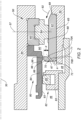
- the bearing assembly 50 discussed in detail below is an example of a present disclosure bearing assembly 50 that may be used between a static structure 52 and a rotating shaft 54.
- An engine centerline 30 is shown above the bearing assembly 50 to indicate the orientation of the bearing assembly 50 as shown in FIG. 2 .
- the bearing assembly 50 includes a bearing 56 and a seal subassembly 80.
- the difference in air pressure across the seal element 82 causes a flow of air (“leakage airflow") to pass between the seal ring 85 and the seal runner 84 during operational segments of the gas turbine engine 20.
- the characteristics (i.e., volumetric rate of flow, air velocity) of the leakage airflow will depend both on the magnitude of the pressure difference across the seal element 82 as well as the size of the gap between the seal ring 85 and the seal surface 93 of the seal runner 84.
- Thermal gradients within the engine during operational segments may cause the temperature of rotating shaft 54 to differ from that of the static structure 52, and thermal expansion of the components may cause the gap between the seal element 82 and the seal surface 93 of the seal runner 84 to vary in magnitude.
- the gap between the seal ring 85 and the annular seal surface 93 may be circumferentially uniform, or it may vary at different circumferential locations.
- the protrusion 98 is also understood to block at least some of the leakage airflow traveling axially.
- the curved surface 96 is understood to direct leakage airflow away from the seal runner 84 and towards the shield member 66 of the outer race 62 (diagrammatically shown as arrow 86). In this manner, at least a portion of the leakage airflow is directed away from the bearing cavity 90. That same portion of leakage airflow directed away from the bearing cavity 90 by the curved surface 96 may also interfere with any leakage airflow traveling axially and thereby impede its axial progress.
- the bearing assembly 50 is configured to not only accommodate component radial variances as described above but is also configured to accommodate relative axial travel between the rotating shaft 54 (and elements attached thereto) and the static structure 52 (and components attached thereto).
- FIG. 2 illustrates the bearing assembly 50 in a first axial position configuration
- FIG. 3 illustrates the bearing assembly 50 in a second axial position configuration.
- FIG. 3 diagrammatically illustrates the relative axial movement by the distance "AM". The differences in axial positions can be seen, for example by the relative axial positions of the seal runner 84 and the outer race 62.
Landscapes
- Engineering & Computer Science (AREA)
- Chemical & Material Sciences (AREA)
- Combustion & Propulsion (AREA)
- Mechanical Engineering (AREA)
- General Engineering & Computer Science (AREA)
- Rolling Contact Bearings (AREA)
Applications Claiming Priority (1)
| Application Number | Priority Date | Filing Date | Title |
|---|---|---|---|
| US18/377,397 US12398674B2 (en) | 2023-10-06 | 2023-10-06 | Bearing assembly for a gas turbine engine |
Publications (2)
| Publication Number | Publication Date |
|---|---|
| EP4534808A2 true EP4534808A2 (de) | 2025-04-09 |
| EP4534808A3 EP4534808A3 (de) | 2025-06-11 |
Family
ID=93014919
Family Applications (1)
| Application Number | Title | Priority Date | Filing Date |
|---|---|---|---|
| EP24205048.2A Pending EP4534808A3 (de) | 2023-10-06 | 2024-10-07 | Lageranordnung für einen gasturbinenmotor |
Country Status (3)
| Country | Link |
|---|---|
| US (1) | US12398674B2 (de) |
| EP (1) | EP4534808A3 (de) |
| CA (1) | CA3255437A1 (de) |
Family Cites Families (20)
| Publication number | Priority date | Publication date | Assignee | Title |
|---|---|---|---|---|
| US2992842A (en) * | 1958-04-21 | 1961-07-18 | United Aircraft Corp | Oil scrubbed face seal |
| US2990202A (en) * | 1958-09-18 | 1961-06-27 | United Aircraft Corp | Labyrinth face seal plate |
| GB988500A (en) * | 1964-02-21 | 1965-04-07 | Rolls Royce | Bearing |
| GB2043799B (en) | 1979-03-05 | 1983-03-16 | Rolls Royce | Draining oil from bearing |
| US4406460A (en) * | 1982-11-01 | 1983-09-27 | United Technologies Corporation | Anti-weepage valve for rotating seals |
| US4542623A (en) | 1983-12-23 | 1985-09-24 | United Technologies Corporation | Air cooler for providing buffer air to a bearing compartment |
| US4928978A (en) * | 1988-04-07 | 1990-05-29 | United Technologies Corporation | Rotating shaft seal |
| US6579010B2 (en) * | 2001-08-31 | 2003-06-17 | General Electric Company | Retainer nut |
| US20080135336A1 (en) * | 2006-12-11 | 2008-06-12 | Jewess Gordon F | Under race bearing lubrication system for gas turbine engines |
| US7806596B2 (en) * | 2007-08-31 | 2010-10-05 | Hamilton Sundstrand Corporation | High speed bearing system with bind-free axial displacement |
| GB201101226D0 (en) | 2011-01-25 | 2011-03-09 | Rolls Royce Plc | A bearing race for a rolling-element bearing |
| EP2971694B2 (de) | 2013-03-15 | 2021-02-17 | United Technologies Corporation | Abschirmung zur anordnung zwischen einem lager und einem rotierenden dichtungselement |
| WO2015094463A1 (en) * | 2013-12-20 | 2015-06-25 | United Technologies Corporation | Seal runner |
| US9777592B2 (en) | 2013-12-23 | 2017-10-03 | Pratt & Whitney Canada Corp. | Post FBO windmilling bumper |
| US9752616B2 (en) * | 2015-03-27 | 2017-09-05 | Pratt & Withney Canada Corp. | Bearing system with bearing damper |
| US10753219B2 (en) * | 2015-05-26 | 2020-08-25 | Pratt & Whitney Canada Corp. | Internally cooled seal runner and method of cooling seal runner of a gas turbine engine |
| FR3062679B1 (fr) * | 2017-02-07 | 2019-04-19 | Safran Aircraft Engines | Virole de reduction de la surpression au voisinage du joint amont d'une enceinte de palier de turboreacteur |
| CN107060898B (zh) | 2017-06-15 | 2019-03-08 | 中国科学院工程热物理研究所 | 带积流槽的浮环密封组件 |
| US11085330B2 (en) * | 2018-02-19 | 2021-08-10 | Pratt & Whitney Canada Corp. | Seal and bearing assembly with bearing outer portion defining seal static portion |
| US10968774B2 (en) * | 2018-10-11 | 2021-04-06 | Pratt & Whitney Canada Corp. | Bearing housing with baffles |
-
2023
- 2023-10-06 US US18/377,397 patent/US12398674B2/en active Active
-
2024
- 2024-10-03 CA CA3255437A patent/CA3255437A1/en active Pending
- 2024-10-07 EP EP24205048.2A patent/EP4534808A3/de active Pending
Also Published As
| Publication number | Publication date |
|---|---|
| US12398674B2 (en) | 2025-08-26 |
| EP4534808A3 (de) | 2025-06-11 |
| CA3255437A1 (en) | 2025-05-23 |
| US20250116231A1 (en) | 2025-04-10 |
Similar Documents
| Publication | Publication Date | Title |
|---|---|---|
| US11073045B2 (en) | Turbine shroud assembly with case captured seal segment carrier | |
| US5622475A (en) | Double rabbet rotor blade retention assembly | |
| EP3705703B1 (de) | Abschirmung zur anordnung zwischen einem lager und einem rotierenden dichtungselement | |
| US9988934B2 (en) | Gas turbine engines including channel-cooled hooks for retaining a part relative to an engine casing structure | |
| EP1013889B1 (de) | Axiale Gasturbine | |
| US5791871A (en) | Turbine engine rotor assembly blade outer air seal | |
| US10781709B2 (en) | Turbine engine with a seal | |
| EP2776682B1 (de) | Dichtung für eine turbomaschine | |
| US10184345B2 (en) | Cover plate assembly for a gas turbine engine | |
| EP3252280B1 (de) | Umlaufendes plenum für öldämpfer | |
| CA2406479C (en) | Weep plug | |
| EP4375487A2 (de) | Geteilte kolbenringdichtung für eine rotierende anordnung und verfahren zur abdichtung | |
| EP4411115A2 (de) | Dichtungsring | |
| US20190226585A1 (en) | Hydrodynamic Intershaft Piston Ring Seal | |
| EP3608506B1 (de) | Gasturbinenleitschaufel welche einen zapfen mit kühlkanälen beinhaltet | |
| EP4534808A2 (de) | Lageranordnung für einen gasturbinenmotor | |
| US12116897B2 (en) | Turbine stator assembly with a radial degree of freedom between a guide vane assembly and a sealing ring | |
| EP3626933B1 (de) | Hochdruckturbinenrückseitenplatte | |
| US20200032669A1 (en) | Shrouded blade assemblies | |
| US12480419B1 (en) | Outer air seal (OAS) assembly for a gas turbine engine | |
| US20250382893A1 (en) | Shrouded turbine assembly for gas turbine engine | |
| US12326089B2 (en) | Seal assembly for a gas turbine engine | |
| US12366172B1 (en) | Seal assembly for a rotary machine having a flexible joint | |
| US12281576B2 (en) | Turbomachine distributor comprising a gas reintroduction duct with a tangential component | |
| CN119353060A (zh) | 具有至少一个阻尼元件的密封组件 |
Legal Events
| Date | Code | Title | Description |
|---|---|---|---|
| PUAI | Public reference made under article 153(3) epc to a published international application that has entered the european phase |
Free format text: ORIGINAL CODE: 0009012 |
|
| STAA | Information on the status of an ep patent application or granted ep patent |
Free format text: STATUS: THE APPLICATION HAS BEEN PUBLISHED |
|
| AK | Designated contracting states |
Kind code of ref document: A2 Designated state(s): AL AT BE BG CH CY CZ DE DK EE ES FI FR GB GR HR HU IE IS IT LI LT LU LV MC ME MK MT NL NO PL PT RO RS SE SI SK SM TR |
|
| PUAL | Search report despatched |
Free format text: ORIGINAL CODE: 0009013 |
|
| AK | Designated contracting states |
Kind code of ref document: A3 Designated state(s): AL AT BE BG CH CY CZ DE DK EE ES FI FR GB GR HR HU IE IS IT LI LT LU LV MC ME MK MT NL NO PL PT RO RS SE SI SK SM TR |
|
| RIC1 | Information provided on ipc code assigned before grant |
Ipc: F01D 11/00 20060101ALI20250507BHEP Ipc: F01D 25/16 20060101ALI20250507BHEP Ipc: F01D 25/18 20060101AFI20250507BHEP |
|
| STAA | Information on the status of an ep patent application or granted ep patent |
Free format text: STATUS: REQUEST FOR EXAMINATION WAS MADE |
|
| 17P | Request for examination filed |
Effective date: 20251211 |