EP4534798A1 - Beschaufelung für eine turbomaschine, sowie turbomaschine - Google Patents
Beschaufelung für eine turbomaschine, sowie turbomaschine Download PDFInfo
- Publication number
- EP4534798A1 EP4534798A1 EP24195957.6A EP24195957A EP4534798A1 EP 4534798 A1 EP4534798 A1 EP 4534798A1 EP 24195957 A EP24195957 A EP 24195957A EP 4534798 A1 EP4534798 A1 EP 4534798A1
- Authority
- EP
- European Patent Office
- Prior art keywords
- thickening
- blading
- depression
- blades
- blade
- Prior art date
- Legal status (The legal status is an assumption and is not a legal conclusion. Google has not performed a legal analysis and makes no representation as to the accuracy of the status listed.)
- Pending
Links
Images


Classifications
-
- F—MECHANICAL ENGINEERING; LIGHTING; HEATING; WEAPONS; BLASTING
- F01—MACHINES OR ENGINES IN GENERAL; ENGINE PLANTS IN GENERAL; STEAM ENGINES
- F01D—NON-POSITIVE DISPLACEMENT MACHINES OR ENGINES, e.g. STEAM TURBINES
- F01D5/00—Blades; Blade-carrying members; Heating, heat-insulating, cooling or antivibration means on the blades or the members
- F01D5/12—Blades
- F01D5/14—Form or construction
- F01D5/141—Shape, i.e. outer, aerodynamic form
-
- B—PERFORMING OPERATIONS; TRANSPORTING
- B23—MACHINE TOOLS; METAL-WORKING NOT OTHERWISE PROVIDED FOR
- B23P—METAL-WORKING NOT OTHERWISE PROVIDED FOR; COMBINED OPERATIONS; UNIVERSAL MACHINE TOOLS
- B23P15/00—Making specific metal objects by operations not covered by a single other subclass or a group in this subclass
- B23P15/02—Making specific metal objects by operations not covered by a single other subclass or a group in this subclass turbine or like blades from one piece
-
- F—MECHANICAL ENGINEERING; LIGHTING; HEATING; WEAPONS; BLASTING
- F01—MACHINES OR ENGINES IN GENERAL; ENGINE PLANTS IN GENERAL; STEAM ENGINES
- F01D—NON-POSITIVE DISPLACEMENT MACHINES OR ENGINES, e.g. STEAM TURBINES
- F01D5/00—Blades; Blade-carrying members; Heating, heat-insulating, cooling or antivibration means on the blades or the members
- F01D5/12—Blades
- F01D5/14—Form or construction
- F01D5/141—Shape, i.e. outer, aerodynamic form
- F01D5/142—Shape, i.e. outer, aerodynamic form of the blades of successive rotor or stator blade-rows
- F01D5/143—Contour of the outer or inner working fluid flow path wall, i.e. shroud or hub contour
-
- F—MECHANICAL ENGINEERING; LIGHTING; HEATING; WEAPONS; BLASTING
- F01—MACHINES OR ENGINES IN GENERAL; ENGINE PLANTS IN GENERAL; STEAM ENGINES
- F01D—NON-POSITIVE DISPLACEMENT MACHINES OR ENGINES, e.g. STEAM TURBINES
- F01D5/00—Blades; Blade-carrying members; Heating, heat-insulating, cooling or antivibration means on the blades or the members
- F01D5/12—Blades
- F01D5/14—Form or construction
- F01D5/141—Shape, i.e. outer, aerodynamic form
- F01D5/145—Means for influencing boundary layers or secondary circulations
-
- F—MECHANICAL ENGINEERING; LIGHTING; HEATING; WEAPONS; BLASTING
- F01—MACHINES OR ENGINES IN GENERAL; ENGINE PLANTS IN GENERAL; STEAM ENGINES
- F01D—NON-POSITIVE DISPLACEMENT MACHINES OR ENGINES, e.g. STEAM TURBINES
- F01D9/00—Stators
- F01D9/02—Nozzles; Nozzle boxes; Stator blades; Guide conduits, e.g. individual nozzles
- F01D9/04—Nozzles; Nozzle boxes; Stator blades; Guide conduits, e.g. individual nozzles forming ring or sector
- F01D9/041—Nozzles; Nozzle boxes; Stator blades; Guide conduits, e.g. individual nozzles forming ring or sector using blades
-
- F—MECHANICAL ENGINEERING; LIGHTING; HEATING; WEAPONS; BLASTING
- F05—INDEXING SCHEMES RELATING TO ENGINES OR PUMPS IN VARIOUS SUBCLASSES OF CLASSES F01-F04
- F05D—INDEXING SCHEME FOR ASPECTS RELATING TO NON-POSITIVE-DISPLACEMENT MACHINES OR ENGINES, GAS-TURBINES OR JET-PROPULSION PLANTS
- F05D2230/00—Manufacture
- F05D2230/10—Manufacture by removing material
-
- F—MECHANICAL ENGINEERING; LIGHTING; HEATING; WEAPONS; BLASTING
- F05—INDEXING SCHEMES RELATING TO ENGINES OR PUMPS IN VARIOUS SUBCLASSES OF CLASSES F01-F04
- F05D—INDEXING SCHEME FOR ASPECTS RELATING TO NON-POSITIVE-DISPLACEMENT MACHINES OR ENGINES, GAS-TURBINES OR JET-PROPULSION PLANTS
- F05D2230/00—Manufacture
- F05D2230/30—Manufacture with deposition of material
-
- F—MECHANICAL ENGINEERING; LIGHTING; HEATING; WEAPONS; BLASTING
- F05—INDEXING SCHEMES RELATING TO ENGINES OR PUMPS IN VARIOUS SUBCLASSES OF CLASSES F01-F04
- F05D—INDEXING SCHEME FOR ASPECTS RELATING TO NON-POSITIVE-DISPLACEMENT MACHINES OR ENGINES, GAS-TURBINES OR JET-PROPULSION PLANTS
- F05D2240/00—Components
- F05D2240/10—Stators
- F05D2240/12—Fluid guiding means, e.g. vanes
- F05D2240/121—Fluid guiding means, e.g. vanes related to the leading edge of a stator vane
-
- F—MECHANICAL ENGINEERING; LIGHTING; HEATING; WEAPONS; BLASTING
- F05—INDEXING SCHEMES RELATING TO ENGINES OR PUMPS IN VARIOUS SUBCLASSES OF CLASSES F01-F04
- F05D—INDEXING SCHEME FOR ASPECTS RELATING TO NON-POSITIVE-DISPLACEMENT MACHINES OR ENGINES, GAS-TURBINES OR JET-PROPULSION PLANTS
- F05D2240/00—Components
- F05D2240/10—Stators
- F05D2240/12—Fluid guiding means, e.g. vanes
- F05D2240/122—Fluid guiding means, e.g. vanes related to the trailing edge of a stator vane
-
- F—MECHANICAL ENGINEERING; LIGHTING; HEATING; WEAPONS; BLASTING
- F05—INDEXING SCHEMES RELATING TO ENGINES OR PUMPS IN VARIOUS SUBCLASSES OF CLASSES F01-F04
- F05D—INDEXING SCHEME FOR ASPECTS RELATING TO NON-POSITIVE-DISPLACEMENT MACHINES OR ENGINES, GAS-TURBINES OR JET-PROPULSION PLANTS
- F05D2240/00—Components
- F05D2240/20—Rotors
- F05D2240/30—Characteristics of rotor blades, i.e. of any element transforming dynamic fluid energy to or from rotational energy and being attached to a rotor
- F05D2240/303—Characteristics of rotor blades, i.e. of any element transforming dynamic fluid energy to or from rotational energy and being attached to a rotor related to the leading edge of a rotor blade
-
- F—MECHANICAL ENGINEERING; LIGHTING; HEATING; WEAPONS; BLASTING
- F05—INDEXING SCHEMES RELATING TO ENGINES OR PUMPS IN VARIOUS SUBCLASSES OF CLASSES F01-F04
- F05D—INDEXING SCHEME FOR ASPECTS RELATING TO NON-POSITIVE-DISPLACEMENT MACHINES OR ENGINES, GAS-TURBINES OR JET-PROPULSION PLANTS
- F05D2240/00—Components
- F05D2240/20—Rotors
- F05D2240/30—Characteristics of rotor blades, i.e. of any element transforming dynamic fluid energy to or from rotational energy and being attached to a rotor
- F05D2240/304—Characteristics of rotor blades, i.e. of any element transforming dynamic fluid energy to or from rotational energy and being attached to a rotor related to the trailing edge of a rotor blade
-
- F—MECHANICAL ENGINEERING; LIGHTING; HEATING; WEAPONS; BLASTING
- F05—INDEXING SCHEMES RELATING TO ENGINES OR PUMPS IN VARIOUS SUBCLASSES OF CLASSES F01-F04
- F05D—INDEXING SCHEME FOR ASPECTS RELATING TO NON-POSITIVE-DISPLACEMENT MACHINES OR ENGINES, GAS-TURBINES OR JET-PROPULSION PLANTS
- F05D2240/00—Components
- F05D2240/80—Platforms for stationary or moving blades
-
- Y—GENERAL TAGGING OF NEW TECHNOLOGICAL DEVELOPMENTS; GENERAL TAGGING OF CROSS-SECTIONAL TECHNOLOGIES SPANNING OVER SEVERAL SECTIONS OF THE IPC; TECHNICAL SUBJECTS COVERED BY FORMER USPC CROSS-REFERENCE ART COLLECTIONS [XRACs] AND DIGESTS
- Y02—TECHNOLOGIES OR APPLICATIONS FOR MITIGATION OR ADAPTATION AGAINST CLIMATE CHANGE
- Y02T—CLIMATE CHANGE MITIGATION TECHNOLOGIES RELATED TO TRANSPORTATION
- Y02T50/00—Aeronautics or air transport
- Y02T50/60—Efficient propulsion technologies, e.g. for aircraft
Definitions
- the invention relates to a blading for a turbomachine according to the preamble of claim 1 and an associated turbomachine, in particular a gas turbine.
- a blade passage of a turbomachine is generally defined by a hub-side and a casing-side sidewall, as well as guide vanes or rotor blades arranged between them.
- the sidewalls may be fixed to either the hub or the casing.
- the influence of wall friction in the area of the sidewalls can sometimes result in strong secondary flows. These secondary flows cause increased losses.
- a significant portion of the flow losses in a turbomachine are generated in the blade passages near the sidewalls. This area is dominated by secondary flows. Measures to reduce these losses include, on the one hand, 3D shaping of the blades near the sidewalls and, on the other hand, deforming the sidewalls themselves, in the area between circumferentially adjacent blades. Both measures are intended to improve flow guidance in the sidewall area, thereby reducing secondary flow and thus flow losses.
- the US 9,963,973 B2 disclose a blading for a turbomachine with a side wall which has a depression on a pressure side of the blade and a thickening on a suction side of the blade.
- US 7,134,842 B2 describes a side wall with a bulge on the pressure side and a depression on the suction side.
- US 9,140,128 B2 shows a depression in the sidewall centrally between two blades, as well as a raised area at the leading edge of the blade.
- the invention is based on the object of providing an improved blading for a turbomachine, as well as an improved turbomachine.
- a first aspect of the invention provides blading for a turbomachine.
- the blading has at least one side wall on which a plurality of blades are formed next to one another, in particular in the circumferential direction.
- Each blade of the plurality of blades defines in particular a leading edge, a trailing edge, a profile chord, a pressure side, and a suction side.
- the side wall between adjacent blades has a depression, in particular in a region of the pressure side, and a first thickening in a region of the suction side. The first thickening begins in particular only at least 10% of the profile depth away from the leading edge.
- blading refers in particular to an arrangement of rotor blades and/or an arrangement of guide vanes, in particular of one or more stages.
- Blading according to the invention is particularly suitable for compressors, in particular high-pressure compressors, as well as for turbines.
- a sidewall within the meaning of the present invention can be on the hub, rotor, and/or housing side and fixed to the hub, rotor, and/or housing.
- a sidewall can comprise the radially inner circumferential surface of a rotor grid and/or the radially outer circumferential surface of a rotor grid.
- the circumferential surfaces can be formed by a shroud fixed to the hub or an inner surface fixed to the housing.
- a sidewall can comprise the housing-side, radially outer circumferential surface and/or the hub-side circumferential surface of a guide vane grid, which can be formed in particular by a shroud fixed to the housing or an outer surface fixed to the hub.
- a depression in the sense of the present invention is understood in particular to be a region of the sidewall that is radially offset into the sidewall with respect to other regions of the sidewall, whereas a thickening or elevation in the sense of the present invention is understood in particular to be a region of the sidewall that protrudes radially from the sidewall with respect to other regions of the sidewall.
- a depression or thickening in the sense of the present invention can protrude or project radially inwards or outwards, in particular with respect to a reference conical surface, in particular a straight or curved one, which is concentric with an axis of rotation.
- the reference conical surface can in particular run through the radially innermost or radially outermost points of the sidewall or therebetween.
- a radius of the reference conical surface can correspond to the mean value of the maximum and minimum or all radial extensions of the sidewall.
- the depression or thickening can also refer to a reference conical surface that runs through a region of the sidewall or a root or tip of the blades.
- a thickening within the meaning of the present invention can be understood in particular as an elevation compared to the depression, and a depression as a depression compared to the thickening.
- a blade passage between two adjacent blades is narrowed by the thickening, while a depression widens it.
- the thickening extends inwards.
- a hub-side thickening thus extends radially positively, and a casing-side thickening extends radially negatively from the sidewall.
- the depression is outwards.
- a hub-side depression thus extends radially negatively, and a housing-side depression extends radially positively from the sidewall.
- a reduction can be achieved by removing material from the sidewall surface, for example, using a milling machine.
- a thickening can be achieved by applying material to a sidewall surface.
- the peaks and valleys represent thickenings and depressions, respectively, relative to the centerline within the meaning of the present invention.
- the valleys (peaks) represent depressions (thickenings) relative to this reference conical surface, while the peaks (valleys) represent thickenings (depressions) because they are located radially further outward (inward).
- Adjacent blades are understood, in particular, to be those that are formed adjacent to one another in the circumferential direction.
- a pressure side of a first blade faces a suction side of an adjacent, second blade.
- both the region of the first thickening and the region of the depression are formed in the side wall between the pressure side of the first blade and the suction side of the second blade.
- the regions can be adjacent to one another or merge into one another.
- the pressure side region is to be understood in particular as an area on the side wall that can be assigned to the pressure side of the respective blade between adjacent blades or that borders the pressure side.
- the suction side region is to be understood in particular as an area on the side wall that can be assigned to the suction side of the respective blade between adjacent blades or that borders the suction side.
- a profile chord of the respective blade represents, in particular, the imaginary connecting line between the upstream leading edge or profile nose and the downstream trailing edge or profile trailing edge.
- the profile depth can, in particular, correspond to the length of the profile chord. Percentages in relation to the profile depth can, in particular, correspond to positional information in the axial direction or in the direction of the profile chord. For example, 0% of the profile depth of the axial position of the leading edge, 100% of the profile depth of the axial position of the trailing edge, and 50% of an axial position midway between the leading edge and trailing edge.
- the first thickening preferably begins at least 10% of the profile depth. In other words, the beginning of the first thickening is at least 10% of a length of the profile depth in the axial direction from the leading edge. In preferred embodiments, the first thickening begins at least 15%, 20%, 25%, 30%, 35%, 40%, 45%, or 50% of the profile depth. The first thickening extends essentially downstream from this starting position. Alternatively, the thickening can begin as early as 5% of the profile depth.
- the depression or first thickening extends over an axial length of at least 10%, preferably at least 30%, in particular at least 50%, 60%, 70%, 80%, 90%, 100%, or more than 100%, in particular up to 130% of a length of the profile depth.
- an extension of the depression in the side wall is greater than an extension of the first thickening. This has been shown to advantageously influence the secondary flows and reduce flow losses.
- an axial extension of the depression on the side wall is greater than an axial extension of the first thickening, and/or an extension in the circumferential direction of the depression on the side wall is greater than an extension in the circumferential direction of the first thickening.
- One embodiment provides that a maximum radial depth of the depression in the sidewall is greater than a maximum radial height of the first thickening on the sidewall. This has been shown to have a beneficial effect on secondary flows and reduce flow losses.
- One embodiment provides for the lowering to begin upstream of the leading edge. This has been shown to have a beneficial effect on secondary flows and reduce flow losses.
- the lowering begins at least 5%, 10%, 15%, 20%, or 25% of the profile depth upstream of the leading edge.
- the cover extends substantially downstream from this starting position.
- An alternative embodiment provides that the reduction begins at 0% of the profile depth, i.e. at the axial position of the leading edge, or downstream of the leading edge, or for example at 5% or 10% of the profile depth.
- the maximum width of the depression corresponds to at least 60% of the width of a blade passage between adjacent blades. This has been shown to advantageously influence secondary flows and reduce flow losses.
- the maximum width can also correspond to at least 65%, 70%, 75%, or 80% of the width of the blade passage.
- the blade passage can also be referred to as a flow channel for the flowing gas of the turbomachine, which can have a substantially curved shape but a substantially constant width. This width can extend, in particular, in the circumferential direction.
- One embodiment provides for the sidewall to have a second thickened portion located upstream of the leading edge. This has been shown to advantageously influence secondary flows and reduce flow losses.
- One embodiment provides for the second thickening to be arranged between two adjacent depressions, particularly when the depression of adjacent blades begins upstream of the leading edge. This has been shown to advantageously influence the secondary flows and reduce flow losses.
- the second thickening can also be understood as a less pronounced depression than the adjacent depressions.
- the second thickening can only represent a thickening relative to the adjacent depressions. It cannot be ruled out that the second thickening could be a depression relative to the reference conical surface.
- One embodiment of the second thickening provides that a maximum of the second thickening is located at least approximately at an imaginary tangent or an imaginary extension upstream of a blade skeleton line of the blade. This has been shown to advantageously influence the secondary flows and reduce flow losses.
- a maximum of the height of the second thickening can be spaced from the leading edge, for example in the form of a bump in front of the leading edge.
- a maximum depth of the depression is between 20% and 60% of the width of the flow channel between adjacent blades from the pressure side, preferably between 20% and 50%, 20% and 40%, or 20% and 30%, or between 30% and 60%, 40% and 60%, or 50% and 60%. This has been shown to advantageously influence the secondary flows and reduce flow losses.
- the depression near the pressure side can thus preferably be less pronounced than in a more distant region of the pressure side or between the blades.
- One embodiment provides for a maximum depth of depression in a range of 20% to 65% of the profile chord between adjacent blades from the pressure side, preferably between 20% and 50%, 20% and 40%, or 20% and 30%, or between 25% and 65%, 35% and 65%, 45% and 65%, or 55% and 65%. This has been shown to have a beneficial effect on secondary flows and reduce flow losses.
- the plurality of blades are rotors or moving blades.
- An alternative embodiment provides that the plurality of blades are stators or guide vanes.
- One embodiment provides that the plurality of blades are compressor blades for a turbomachine.
- An alternative embodiment provides that the plurality of blades are turbine blades for a turbomachine.
- the plurality of blades have blade fillets. It may also be provided that the plurality of blades do not have blade fillets. In particular, the aforementioned embodiments of the blading prove advantageous for blades both with and without blade fillets.
- Blade fillets are bodies with connecting surfaces between the side wall and the blade that have a fillet radius so that no edge is formed between the side wall and the blade.
- a second aspect of the invention provides a turbomachine having at least one blading according to the invention.
- a further aspect of the invention is a machining manufacturing method for producing the blading according to the invention, as well as an additive manufacturing method for producing the blading according to the invention.
- the described components of the embodiment each represent individual, independently of one another, Features of the invention, each of which further develops the invention independently of one another and can therefore be considered a component of the invention, either individually or in a combination other than that shown.
- the described embodiment can also be supplemented by further features of the invention already described.
- Features of the various embodiments can, in particular, be combined with one another.
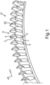
- FIG. 1 shows a perspective view of a blading 21, in particular for a turbomachine, with a hub-side side wall 1 in a compressor stator grid in the hub area, wherein an outer housing wall in the Fig. 1 not shown.
- a plurality of blades 20 having a leading edge 2, a trailing edge 3, a pressure side 4, and a suction side 5 are arranged next to one another in a circumferential direction U.
- a blade passage 8 through which fluid can flow in the axial direction X.
- FIG. 2 1 shows a contour line diagram of a contouring of a side wall 1 according to a first exemplary embodiment, in which isolines 15 of the same height as the extension of the side wall contour are shown in the direction orthogonal to the side wall 1.
- the side wall 1 can have a depression 11 between adjacent blades 20 in a region 6 of the pressure side 4, and a first thickening 10 in a region 7 of the suction side 5.
- the first thickening 10 only begins at least 10% of the profile depth c away from the leading edge 2.
- the first thickening begins at 20% of the profile depth c.
- the extent of the depression 11 is greater than an extent of the first thickening 10, in particular in the axial direction X, as well as in the circumferential direction U. Based on the number of isolines 15, it can also be seen that a maximum depth of the depression 11 is greater than a maximum height of the first thickening 10.
- the depression 11 begins upstream of the leading edge 2, approximately at a distance of 15% of a length of the profile depth c upstream of the leading edge 2.
- the depression 11 has a maximum width in the circumferential direction U of at least 60% of a Width of the blade passage 8 between the adjacent blades 20 in the circumferential direction U.
- a maximum depth of the depression 11 is approximately 40% of a width of the blade passage 8 away from the pressure side 4, and lies approximately in a range of approximately 25% to 60% of the profile depth c.
- the depression 11 and the first thickening 10 can, in particular, directly adjoin one another in the blade passage 8, so that the thickening can smoothly transition into the depression 10.
- Both the depression 11 and the first thickening 10 can extend essentially elongated along the axial direction X. Essentially, this should be understood to mean that the extension in the axial direction X can be greater than the extension in the circumferential direction U.
- the depression 11 and the first thickening 10 can end approximately at the axial position of the trailing edge 3, i.e. at approximately 100% of the profile depth c, or can extend at least slightly downstream beyond the trailing edge 3.
- FIG. 3 shows a contour line diagram of a contouring of a side wall 1 according to a second exemplary embodiment.
- the side wall 1 has a second thickening 12, which is arranged upstream of the leading edge 2.
- a maximum of the second thickening 12 can be arranged at least approximately on an imaginary tangent 13 of a blade skeleton line 9 of the blade 20, or on an imaginary, upstream extension of the blade skeleton line 9.
- the second thickening 12 can be arranged between two adjacent depressions 11 in this example.
- FIG. 4 A contour line diagram of a contouring of a sidewall 1 according to a third exemplary embodiment is shown.
- the maximum depth of the depression 11 can be significantly greater than the maximum height of the first thickening 10.
- the depression 11 can begin approximately at 0% of the profile depth c or approximately at the axial position of the leading edge.
Landscapes
- Engineering & Computer Science (AREA)
- Mechanical Engineering (AREA)
- Physics & Mathematics (AREA)
- Fluid Mechanics (AREA)
- General Engineering & Computer Science (AREA)
- Structures Of Non-Positive Displacement Pumps (AREA)
Abstract
Die Erfindung betrifft eine Beschaufelung (21) für eine Turbomaschine, sowie eine Turbomaschine, welche verbesserte Strömungseigenschaften aufweisen. Die Beschaufelung (21) weist eine Seitenwand (1) auf, an welcher eine Vielzahl von Schaufeln nebeneinander ausgebildet sind, wobei jeweils eine Schaufel (20) der Vielzahl von Schaufeln eine Eintrittskante (2), eine Austrittskante (3), eine Profiltiefe (c), eine Druckseite (4) und eine Saugseite (5) aufweist, wobei die Seitenwand (1) zwischen benachbarten Schaufeln (20) in einem Bereich (6) der Druckseite (4) eine Aufdickung (11) und in einem Bereich (7) der Saugseite (5) eine erste Aufdickung (10) aufweist. Die erste Aufdickung (10) beginnt hierbei erst ab zumindest 10 % der Profiltiefe (c) entfernt von der Eintrittskante (2).
Description
- Die Erfindung betrifft eine Beschaufelung für eine Turbomaschine nach dem Oberbegriff des Anspruchs 1 und eine zugehörige Turbomaschine, insbesondere eine Gasturbine.
- Eine Schaufelpassage einer Turbomaschine wird allgemein durch eine naben- und eine gehäuseseitige Seitenwand sowie dazwischen angeordnete Leit- oder Laufschaufeln definiert, wobei die Seitenwände jeweils naben- oder gehäusefest sein können. In den Schaufelpassagen können sich durch den Einfluss der Wandreibung im Bereich der Seitenwände teilweise stark ausgeprägte Sekundärströmungen ergeben. Diese Sekundärströmungen verursachen erhöhte Verluste.
- Ein bedeutender Anteil der Strömungsverluste in einer Turbomaschine wird in den Schaufelpassagen im Bereich der Seitenwände erzeugt. Dieser Bereich ist dominiert von Sekundärströmungen. Maßnahmen, diese Verluste zu reduzieren, sind einerseits 3D-Formgebungen der Schaufeln nahe der Seitenwände und andererseits die Verformung der Seitenwände selbst, im Bereich zwischen in Umfangsrichtung benachbarten Schaufeln. Beide Maßnahmen sollen die Strömungsführung im Bereich der Seitenwände verbessern, dadurch die Sekundärströmung und damit die Strömungsverluste reduzieren.
- Es gibt mittlerweile verschiedenste Lösungen zur Formgebung von Seitenwänden in Turbomaschinen. Es ist aber nach wie vor sehr anspruchsvoll, individuelle Lösungen finden, die sowohl zu einer maximalen Verlustreduzierung im Auslegungspunkt der Turbomaschine führen, als auch in Betriebsbereichen abseits der Auslegung (Offdesign) gut funktionieren, bzw. dort keine negativen Auswirkungen auf die Strömung in der Turbomaschine haben. Es besteht erheblicher Bedarf, die Formgebung von Seitenwänden weiter zu verbessern.
- Die
US 9,963,973 B2 EP 2 631 429 B1 offenbaren eine Beschaufelung für eine Turbomaschine mit einer Seitenwand, welche eine Absenkung an einer Druckseite der Schaufel und eine Aufdickung an einer Saugseite der Schaufel aufweist. - Die
US 7,134,842 B2 beschreibt eine Seitenwand mit einer Ausbuchtung an der Druckseite und eine Vertiefung an der Saugseite. DieUS 9,140,128 B2 - Der Erfindung liegt die Aufgabe zugrunde, eine verbesserte Beschaufelung für eine Turbomaschine, sowie eine verbesserte Turbomaschine bereitzustellen.
- Die Aufgabe wird durch die Gegenstände der unabhängigen Patentansprüche gelöst. Vorteilhafte Weiterbildungen der Erfindung sind durch die abhängigen Patentansprüche, die folgende Beschreibung sowie die Figuren beschrieben.
- Durch einen ersten Aspekt der Erfindung ist eine Beschaufelung für eine Turbomaschine bereitgestellt. Die Beschaufelung weist zumindest eine Seitenwand auf, an welcher eine Vielzahl von Schaufeln, insbesondere in Umfangsrichtung, nebeneinander ausgebildet sind. Jeweils eine Schaufel der Vielzahl von Schaufeln definiert insbesondere eine Eintrittskante, eine Austrittskante, eine Profilsehne, eine Druckseite und eine Saugseite. Die Seitenwand zwischen benachbarten Schaufeln weisen insbesondere in einem Bereich der Druckseite eine Absenkung und in einem Bereich der Saugseite eine erste Aufdickung auf. Die erste Aufdickung beginnt insbesondere erst ab zumindest 10 % der Profiltiefe entfernt von der Eintrittskante.
- Durch dieses gezielte und kombinierte Anbringen von Aufdickungen und Vertiefungen der Seitenwand in den Bereichen der Druck- bzw. Saugseite, wobei die erste Aufdickung erst ab zumindest 10 % der Profiltiefe beginnt, hat es sich gezeigt, dass eine vorteilhafte lokale Anpassung des statischen Druckes und der Strömungsgeschwindigkeit erreicht werden kann, wodurch die Sekundärströmungen vorteilhaft beeinflusst und die Strömungsverluste verringert werden können. Neben der Verlustverringerung in den Schaufelkanälen über einen großen Betriebsbereich der Turbomaschinen kann ein weiterer Vorteil dieser Ausgestaltung auch in einer Vergrößerung des Betriebsbereichs der Turbomaschinen liegen. Ein Vorteil kann auch in einer einfachen konstruktiven Umsetzung und/oder der Anwendbarkeit für bereits bestehende Auslegungen von Turbomaschinen liegen.
- Als Beschaufelung im Sinne der vorliegenden Erfindung wird insbesondere eine Anordnung von Laufschaufeln und/oder eine Anordnung von Leitschaufeln, insbesondere einer oder mehrerer Stufen, bezeichnet. Eine erfindungsgemäße Beschaufelung ist besonders für Verdichter, insbesondere Hochdruckverdichter, als auch für Turbinen geeignet.
- Eine Seitenwand im Sinne der vorliegenden Erfindung kann naben- bzw. rotor- und/oder gehäuseseitig sowie naben- bzw. rotor- und/oder gehäusefest sein. So kann eine Seitenwand die radial innere Umfangsfläche eines Laufgitters, und/oder die radial äußere Umfangsfläche eines Laufgitters umfassen. Insbesondere können die Umfangsflächen durch ein nabenfestes Deckband oder eine gehäusefeste Innenfläche gebildet sein. Gleichermaßen kann eine Seitenwand die gehäuseseitige, radial äußere Umfangsfläche und/oder die nabenseitige Umfangsfläche eines Leitgitters umfassen, die insbesondere durch ein gehäusefestes Deckband oder eine nabenfeste Außenfläche gebildet sein kann.
- Unter einer Vertiefung im Sinne der vorliegenden Erfindung wird insbesondere ein Bereich der Seitenwand verstanden, der in Bezug zu anderen Bereichen der Seitenwand radial in die Seitenwand versetzt ist, während unter einer Aufdickung bzw. Erhöhung im Sinne der vorliegenden Erfindung insbesondere ein Bereich der Seitenwand verstanden wird, der in Bezug zu anderen Bereichen der Seitenwand radial aus der Seitenwand hervorsteht. Eine Vertiefung bzw. Aufdickung im Sinne der vorliegenden Erfindung kann insbesondere in Bezug zu einer, insbesondere geraden oder gekrümmten, Bezugskegelfläche radial nach innen bzw. außen zurück- bzw. überstehen, die konzentrisch zu einer Rotationsachse liegt. Die Bezugskegelfläche kann insbesondere durch die radial innersten oder radial äußersten Punkte der Seitenwand oder dazwischen verlaufen. Insbesondere kann ein Radius der Bezugskegelfläche dem Mittelwert der maximalen und minimalen oder aller radialen Erstreckungen der Seitenwand entsprechen. Weiterhin kann sich die Vertiefung bzw. Aufdickung auch auf eine Bezugskegelfläche beziehen, die durch einen Bereich der Seitenwand oder einen Fuß oder eine Spitze der Schaufeln verläuft.
- Unter einer Aufdickung im Sinne der vorliegenden Erfindung kann insbesondere eine Erhöhung im Vergleich zu der Vertiefung verstanden werden, unter einer Vertiefung entsprechend eine Absenkung im Vergleich zu der Aufdickung. Mit anderen Worten wird durch die Aufdickung eine Schaufelpassage zwischen zwei benachbarten Schaufeln verengt, sowie durch eine Absenkung erweitert.
- Aus Sicht von innerhalb des durchströmten Kanals ist die Aufdickung nach innen gehend. Eine nabenseitige Aufdickung erstreckt sich somit radial positiv, und eine gehäuseseitige Aufdickung radial negativ aus der Seitenwand. Aus Sicht von innerhalb des durchströmten Kanals ist die Absenkung nach außen gehend. Eine nabenseitige Absenkung erstreckt sich somit radial negativ, und eine gehäuseseitige Absenkung radial positiv aus der Seitenwand.
- Beispielsweise kann eine Absenkung durch Abtragen von Material von der Seitenwandoberfläche erfolgen, beispielsweise mittels einer Fräse. Beispielsweise kann eine Aufdickung durch Auftragen von Material auf eine Seitenwandoberfläche erfolgen.
- Denkt man sich beispielsweise eine in Umfangsrichtung sinusförmig gewellte Seitenwand, so stellen die Berge bzw. Täler Aufdickungen bzw. Vertiefungen im Sinne der vorliegenden Erfindung gegenüber der Mittellinie dar. Gleichermaßen kann man von einer Bezugskegelfläche durch die radial maximalen oder minimalen Amplituden der sinusförmig gewellten Seitenwand ausgehen. Auch dann stellen die Täler (Berge) Vertiefungen (Aufdickungen) relativ zu dieser Bezugskegelfläche dar, die Berge (Täler) Aufdickungen (Vertiefungen), da sie demgegenüber radial weiter außen (innen) liegen.
- Unter benachbarten Schaufeln sind insbesondere solche zu verstehen, die in der Umfangsrichtung benachbart zueinander ausgebildet sind. Insbesondere ist jeweils eine Druckseite einer ersten Schaufel einer Saugseite einer benachbarten, zweiten Schaufel zugekehrt. Insbesondere in der Seitenwand zwischen der Druckseite der ersten Schaufel und der Saugseite der zweiten Schaufel ist sowohl der Bereich der ersten Aufdickung, als auch der Bereich der Absenkung ausgebildet. Beispielsweise können die Bereiche aneinander angrenzen bzw. ineinander übergehen.
- Der Bereich der Druckseite ist insbesondere als ein Bereich auf der Seitenwand zu verstehen, der zwischen benachbarten Schaufeln der Druckseite der jeweiligen Schaufel zugeordnet werden kann bzw. an der Druckseite angrenzt. Der Bereich der Saugseite ist insbesondere als ein Bereich auf der Seitenwand zu verstehen, der zwischen benachbarten Schaufeln der Saugseite der jeweiligen Schaufel zugeordnet werden kann bzw. an der Saugseite angrenzt.
- Eine Profilsehne der jeweiligen Schaufel stellt insbesondere die gedachte Verbindungslinie zwischen der stromauf befindlichen Eintrittskante bzw. Profilnase und der stromab gerichteten Austrittskante bzw. Profilhinterkante dar. Die Profiltiefe kann insbesondere der Länge der Profilsehne entsprechen. Prozentangaben in Bezug auf die Profiltiefe können insbesondere Positionsangaben in axialer Richtung bzw. in Richtung der Profilsehne entsprechen. Beispielsweise entspricht 0 % der Profiltiefe der axialen Position der Eintrittskante, 100 % der Profiltiefe der axialen Position der Austrittskante, und 50 % eine axiale Position mittig zwischen der Eintrittskante und Austrittskante.
- Die erste Aufdickung beginnt vorzugsweise erst ab zumindest 10 % der Profiltiefe. Mit anderen Worten ist der Beginn der ersten Aufdickung zumindest 10 % einer Länge der Profiltiefe in axialer Richtung von der Eintrittskante entfernt. In bevorzugten Ausführungsvarianten beginnt die erste Aufdickung erst ab zumindest 15 %, 20 %, 25 %, 30 %, 35 %, 40 %, 45 % oder 50 % der Profiltiefe. Die erste Aufdickung erstreckt sich dabei von dieser Beginnposition im Wesentlichen stromab. Alternativ kann die Aufdickung bereits ab 5 % der Profiltiefe beginnen.
- Bevorzugt erstreckt sich die Vertiefung bzw. erste Aufdickung über eine axiale Länge von wenigstens 10%, vorzugsweise wenigstens 30%, insbesondere wenigstens 50 %, 60%, 70 % 80 %, 90 %, 100 %, oder mehr als 100 %, insbesondere bis zu 130 % einer Länge der Profiltiefe.
- Eine Ausführungsform sieht vor, dass eine Erstreckung der Absenkung der Seitenwand größer ist als eine Erstreckung der ersten Aufdickung. Dadurch hat sich gezeigt, dass die Sekundärströmungen vorteilhaft beeinflusst und die Strömungsverluste verringert werden können. Insbesondere ist eine axiale Erstreckung der Absenkung auf der Seitenwand größer als eine axiale Erstreckung der ersten Aufdickung, und/oder eine Erstreckung in Umfangsrichtung der Absenkung auf der Seitenwand größer als eine Erstreckung in Umfangsrichtung der ersten Aufdickung
- Eine Ausführungsform sieht vor, dass eine maximale, radiale Tiefe der Absenkung in die Seitenwand größer ist als eine maximale, radiale Höhe der ersten Aufdickung auf der Seitenwand. Dadurch hat sich gezeigt, dass die Sekundärströmungen vorteilhaft beeinflusst und die Strömungsverluste verringert werden können.
- Eine Ausführungsform sieht vor, dass die Absenkung stromauf der Eintrittskante beginnt. Dadurch hat sich gezeigt, dass die Sekundärströmungen vorteilhaft beeinflusst und die Strömungsverluste verringert werden können.
- Vorzugsweise beginnt die Absenkung zumindest 5 %, 10 %, 15 %, 20 % oder 25 % einer Länge der Profiltiefe stromauf der Eintrittskante. Die Abdeckung erstreckt sich dabei von dieser Beginnposition im Wesentlichen stromab.
- Eine alternative Ausführungsform sieht vor, dass die Absenkung ab 0 % der Profiltiefe, also auf axialer Position der Eintrittskante, oder stromab der Eintrittskante beginnt, oder beispielsweise bei 5 % oder 10 % der Profiltiefe.
- Eine Ausführungsform sieht vor, dass eine maximale Breite der Absenkung zumindest 60 % einer Breite einer Schaufelpassage zwischen benachbarten Schaufeln entspricht. Dadurch hat sich gezeigt, dass die Sekundärströmungen vorteilhaft beeinflusst und die Strömungsverluste verringert werden können. Die maximale Breite kann auch zumindest 65 %, 70 %, 75 % oder 80 % der Breite der Schaufelpassage entsprechen.
- Die Schaufelpassage kann auch als Durchflusskanal für das strömende Gas der Turbomaschine bezeichnet werden, welche im Wesentlichen eine gekrümmte Form, aber eine im Wesentlichen konstante Breite aufweisen kann. Die Breite kann sich insbesondere im Umfangsrichtung erstrecken.
- Eine Ausführungsform sieht vor, dass die Seitenwand eine zweite Aufdickung aufweist, welche stromauf der Eintrittskante angeordnet ist. Dadurch hat sich gezeigt, dass die Sekundärströmungen vorteilhaft beeinflusst und die Strömungsverluste verringert werden können.
- Eine Ausführungsform sieht vor, dass die zweite Aufdickung zwischen zwei benachbarten Absenkungen angeordnet ist, insbesondere wenn die Absenkung benachbarter Schaufeln stromauf der Eintrittskante beginnt. Dadurch hat sich gezeigt, dass die Sekundärströmungen vorteilhaft beeinflusst und die Strömungsverluste verringert werden können.
- Die zweite Aufdickung kann auch als eine weniger starke Absenkung verstanden werden als die benachbarten Absenkungen. Mit anderen Worten kann die zweite Aufdickung lediglich eine Aufdickung in Bezug zu den benachbarten Absenkungen darstellen. Dabei ist nicht ausgeschlossen, dass die zweite Aufdickung in Bezug zu der Bezugskegelfläche eine Absenkung sein kann.
- Eine Ausführungsform der zweiten Aufdickung sieht vor, dass ein Maximum der zweiten Aufdickung zumindest näherungsweise an einer gedachten Tangente bzw. eine gedachte Verlängerung stromauf einer Schaufelskeletlinie der Schaufel angeordnet ist. Dadurch hat sich gezeigt, dass die Sekundärströmungen vorteilhaft beeinflusst und die Strömungsverluste verringert werden können.
- Vorzugsweise kann ein Maximum der Höhe der zweiten Aufdickung beabstandet zu der Eintrittskante sein, beispielsweise in Form einer Beule vor der Eintrittskante.
- Eine Ausführungsform sieht vor, dass eine maximale Tiefe der Absenkung zwischen 20 % und 60 % der Breite des Durchflusskanals zwischen benachbarten Schaufeln von der Druckseite entfernt ist, vorzugsweise zwischen 20 % und 50 %, 20 % und 40 %, oder 20 % und 30 %, bzw. zwischen 30 % und 60 %, 40 % und 60 %, oder 50 % und 60 %. Dadurch hat sich gezeigt, dass die Sekundärströmungen vorteilhaft beeinflusst und die Strömungsverluste verringert werden können. Die Absenkung in der Nähe der Druckseite kann somit vorzugsweise weniger stark ausgeprägt sein als in einem entfernteren Bereich der Druckseite bzw. als zwischen den Schaufeln.
- Eine Ausführungsform sieht vor, dass eine maximale Tiefe der Absenkung in einem Bereich von 20 % bis 65 % der Profilsehne zwischen benachbarten Schaufeln von der Druckseite liegt, vorzugsweise zwischen 20 % und 50 %, 20 % und 40 %, oder 20 % und 30 %, bzw. zwischen 25 % und 65 %, 35 % und 65 %, 45 % und 65 %, oder 55 % und 65 %. Dadurch hat sich gezeigt, dass die Sekundärströmungen vorteilhaft beeinflusst und die Strömungsverluste verringert werden können.
- Eine Ausführungsform sieht vor, dass die Vielzahl von Schaufeln Rotoren bzw. Laufschaufeln sind. Eine alternative Ausführungsform sieht vor, dass die Vielzahl von Schaufeln Statoren bzw. Leitschaufeln sind.
- Eine Ausführungsform sieht vor, dass die Vielzahl von Schaufeln Verdichterschaufeln für eine Turbomaschine sind. Eine alternative Ausführungsform sieht vor, dass die Vielzahl von Schaufeln Turbinenschaufeln für eine Turbomaschine sind.
- Eine Ausführungsform sieht vor, dass die Vielzahl von Schaufeln Schaufelfillets aufweisen. Ebenso kann es vorgesehen sein, dass die Vielzahl von Schaufeln keine Schaufelfillets aufweisen. Insbesondere erweisen sich die genannten Ausführungsformen der Beschaufelung als vorteilhaft für Schaufeln sowohl mit Schaufelfillets als auch ohne Schaufelfillets.
- Als Schaufelfillets werden Körper mit Verbindungsflächen zwischen der Seitenwand und der Schaufel bezeichnet, die einen Ausrundungsradius aufweisen, sodass keine Kante zwischen Seitenwand und der Schaufel ausgebildet ist.
- Durch einen zweiten Aspekt der Erfindung ist eine Turbomaschine bereitgestellt, die zumindest eine erfindungsgemäße Beschaufelung aufweist.
- Ein weiterer Aspekt der Erfindung ist ein zerspanendes Fertigungsverfahren zur Herstellung der erfindungsgemäßen Beschaufelung, sowie ein additives Fertigungsverfahren zur Herstellung der erfindungsgemäßen Beschaufelung.
- Im Folgenden ist sind Ausführungsbeispiele der Erfindung beschrieben. Hierzu zeigt:
- FIG. 1
- eine perspektivische Darstellung eines Ausführungsbeispiels einer erfindungsgemäßen Beschaufelung;
- FIG. 2
- ein Höhenliniendiagramm einer Konturierung einer Seitenwand gemäß einem ersten Ausführungsbeispiel;
- FIG. 3
- ein Höhenliniendiagramm einer Konturierung einer Seitenwand gemäß einem zweiten Ausführungsbeispiel;
- FIG. 4
- ein Höhenliniendiagramm einer Konturierung einer Seitenwand gemäß einem dritten Ausführungsbeispiel.
- Bei dem im Folgenden erläuterten Ausführungsbeispielen handelt es sich um eine bevorzugte Ausführungsform der Erfindung. Bei den Ausführungsbeispielen stellen die beschriebenen Komponenten der Ausführungsform jeweils einzelne, unabhängig voneinander zu betrachtende Merkmale der Erfindung dar, welche die Erfindung jeweils auch unabhängig voneinander weiterbilden und damit auch einzeln oder in einer anderen als der gezeigten Kombination als Bestandteil der Erfindung anzusehen sind. Des Weiteren ist die beschriebene Ausführungsform auch durch weitere der bereits beschriebenen Merkmale der Erfindung ergänzbar. Merkmale der verschiedenen Ausführungsbeispiele können insbesondere miteinander kombiniert werden.
- In den Figuren bezeichnen gleiche Bezugszeichen jeweils funktionsgleiche Elemente.
-
FIG. 1 zeigt eine perspektivische Darstellung einer Beschaufelung 21. insbesondere für eine Turbomaschine, mit einer nabenseitigen Seitenwand 1 bei einem Verdichter-Statorgitter im Nabenbereich, wobei eine äußere Gehäusewand in derFig. 1 nicht dargestellt ist. Auf der Seitenwand 1 ist eine Vielzahl von Schaufeln 20 mit einer Eintrittskante 2, einer Austrittskante3, einer Druckseite 4 und einer Saugseite 5 in einer Umfangsrichtung U nebeneinander angeordnet. Zwischen benachbarten Schaufeln 20 befindet sich eine Schaufelpassage 8, durch welches Fluid in axialer Richtung X strömen kann. - In der
FIG. 2 ist ein Höhenliniendiagramm einer Konturierung einer Seitenwand 1 gemäß einem ersten Ausführungsbeispiel gezeigt, bei welchem Isolinien 15 gleicher Höhe der Erstreckung der Seitenwandkontur in die zur Seitenwand 1 orthogonalen Richtung dargestellt sind. Die Seitenwand 1 kann zwischen benachbarten Schaufeln 20 in einem Bereich 6 der Druckseite 4 eine eine Absenkung 11 aufweisen, sowie in einem Bereich 7 der Saugseite 5 eine erste Aufdickung10 aufweisen. Insbesondere kann es vorgesehen sein, dass die erste Aufdickung 10 erst ab zumindest 10 % der Profiltiefe c entfernt von der Eintrittskante 2 beginnt. Im gezeigten Ausführungsbeispiel beginnt die erste Aufdickung bei 20 % der Profiltiefe c. - Insbesondere ist gemäß diesem Ausführungsbeispiel die Erstreckung der Absenkung 11 größer ist als eine Erstreckung der ersten Aufdickung 10, insbesondere in axialer Richtung X, als auch in Umfangsrichtung U. Anhand der Anzahl der Isolinien 15 ist zudem erkennbar, dass eine maximale Tiefe der Absenkung 11 größer ist als eine maximale Höhe der ersten Aufdickung 10.
- Die Absenkung 11 beginnt in diesem Beispiel stromauf der Eintrittskante 2 beginnt, etwa mit einem Abstand von 15 % einer Länge der Profiltiefe c stromauf von der Eintrittskante 2. Ebenso weist die Absenkung 11 eine maximale Breite in Umfangsrichtung U von zumindest 60 % einer Breite der Schaufelpassage 8 zwischen den benachbarten Schaufeln 20 in Umfangsrichtung U. Eine maximale Tiefe der Absenkung 11 ist hierbei etwa 40 % einer Breite der Schaufelpassage 8 von der Druckseite 4 entfernt, und liegt in etwa in einem Bereich von ca. 25 % bis 60 % der Profiltiefe c.
- Die Absenkung 11 und die erste Aufdickung 10 können insbesondere direkt aneinander in der Schaufelpassage 8 angrenzen, sodass die Aufdickung in die Absenkung 10 fließend übergehen kann. Sowohl die Absenkung 11 als auch die erste Aufdickung 10 können sich im Wesentlichen länglich entlang der axialen Richtung X erstrecken. Im Wesentlichen ist hierbei derart zu verstehen, dass die Erstreckung in axialer Richtung X größer sein kann als die Erstreckung in Umfangsrichtung U.
- Die Absenkung 11 und die erste Aufdickung 10 können in etwa auf axialer Position der Austrittskante 3, also bei etwa 100 % der Profiltiefe c enden, bzw. noch zumindest geringfügig stromab über die Austrittskante 3 hinausgehen.
-
FIG. 3 zeigt ein Höhenliniendiagramm einer Konturierung einer Seitenwand 1 gemäß einem zweiten Ausführungsbeispiel. Im Vergleich zum ersten Beispiel ist die Erstreckung der Absenkung 11 noch weiter deutlich größer als die Erstreckung der ersten Aufdickung 10. Zusätzlich weist die Seitenwand 1 eine zweite Aufdickung 12 auf, welche stromauf der Eintrittskante 2 angeordnet ist. Ein Maximum der zweiten Aufdickung 12 kann im gezeigten Beispiel zumindest näherungsweise an einer gedachten Tangente 13 einer Schaufelskeletlinie 9 der Schaufel 20 angeordnet sein, bzw. an einer gedachten, stromaufwärtigen Verlängerung der Schaufelskeletlinie 9. Insbesondere in der Konstellation, dass die Absenkung 11 bereits stromauf der Eintrittskante 2 beginnt, kann die zweite Aufdickung 12 in diesem Beispiel zwischen zwei benachbarten Absenkungen 11 angeordnet sein. - In der
FIG. 4 ist ein Höhenliniendiagramm einer Konturierung einer Seitenwand 1 gemäß einem dritten Ausführungsbeispiel gezeigt. Die maximale Tiefe der Absenkung 11 kann hierbei deutlich größer sein als die maximale Höhe der ersten Aufdickung 10. Die Absenkung 11 kann hierbei in etwa ab 0 % der Profiltiefe c bzw. in etwa ab der axialen Position der Eintrittskante beginnen. -
- 1
- Seitenwand
- 2
- Eintrittskante
- 3
- Austrittskante
- 4
- Druckseite
- 5
- Saugseite
- 6
- Bereich der Druckseite der Seitenwand
- 7
- Bereich der Saugseite der Seitenwand
- 8
- Schaufelpassage
- 9
- Skelettlinie
- 10
- erste Aufdickung
- 11
- Absenkung
- 12
- zweite Aufdickung
- 13
- Tangente
- 14
- Profilsehne
- 15
- Isolinien
- 20
- Schaufel
- 21
- Beschaufelung
- c
- Profiltiefe
- U
- Umfangsrichtung
- X
- axiale Richtung
Claims (15)
- Beschaufelung (21) für eine Turbomaschine, aufweisend eine Seitenwand (1), an welcher eine Vielzahl von Schaufeln nebeneinander ausgebildet sind, wobei jeweils eine Schaufel (20) der Vielzahl von Schaufeln eine Eintrittskante (2), eine Austrittskante (3), eine Profiltiefe (c), eine Druckseite (4) und eine Saugseite (5) aufweist, wobei die Seitenwand (1) zwischen benachbarten Schaufeln (20) in einem Bereich (6) der Druckseite (4) eine Absenkung (11) und in einem Bereich (7) der Saugseite (5) eine erste Aufdickung (10) aufweist,
dadurch gekennzeichnet, dass
die erste Aufdickung (10) erst ab zumindest 10 % der Profiltiefe (c) entfernt von der Eintrittskante (2) beginnt. - Beschaufelung (21) nach Anspruch 1, dadurch gekennzeichnet, dass
eine Erstreckung der Absenkung (11) größer ist als eine Erstreckung der ersten Aufdickung (10). - Beschaufelung (21) nach Anspruch 1 oder 2, dadurch gekennzeichnet, dass
eine maximale Tiefe der Absenkung (11) größer ist als eine maximale Höhe der ersten Aufdickung (10). - Beschaufelung (21) nach einem der vorherigen Ansprüche, dadurch gekennzeichnet, dass
die Absenkung (11) stromauf der Eintrittskante (2) beginnt, vorzugsweise zumindest 10 % einer Länge der Profiltiefe (c) stromauf der Eintrittskante (2). - Beschaufelung (21) nach einem der Ansprüche 1 bis 3, dadurch gekennzeichnet, dass
die Absenkung (11) ab 0 % der Profiltiefe (c) oder stromab der Eintrittskante (2) beginnt. - Beschaufelung (21) nach einem der Ansprüche 1 bis 3, dadurch gekennzeichnet, dass
eine maximale Breite der Absenkung (11) zumindest 60 % einer Breite einer Schaufelpassage (8) zwischen benachbarten Schaufeln (20) entspricht. - Beschaufelung (21) nach einem der vorherigen Ansprüche, dadurch gekennzeichnet, dass
die Seitenwand (1) eine zweite Aufdickung (12) aufweist, welche stromauf der Eintrittskante (2) angeordnet ist. - Beschaufelung (21) nach Anspruch 4 und 7, dadurch gekennzeichnet, dass
die zweite Aufdickung (12) zwischen zwei benachbarten Absenkungen (11) angeordnet ist. - Beschaufelung (21) nach Anspruch 7 und 8, dadurch gekennzeichnet, dass
ein Maximum der zweiten Aufdickung (12) zumindest näherungsweise an einer gedachten Tangente (13) einer Schaufelskeletlinie (9) der Schaufel (20) angeordnet ist. - Beschaufelung (21) nach einem der vorherigen Ansprüche, dadurch gekennzeichnet, dass eine maximale Tiefe der Absenkung (11) zwischen 20 % und 60 % einer Breite einer Schaufelpassage (8) zwischen benachbarten Schaufeln (20) von der Druckseite (4) entfernt ist.
- Beschaufelung (21) nach einem der vorherigen Ansprüche, dadurch gekennzeichnet, dass eine maximale Tiefe der Absenkung (11) in einem Bereich von 20 % bis 65 % der Profiltiefe (c) liegt.
- Beschaufelung (21) nach einem der vorherigen Ansprüche, dadurch gekennzeichnet, dass die Vielzahl von Schaufeln (20) Rotoren oder Statoren sind.
- Beschaufelung (21) nach einem der vorherigen Ansprüche, dadurch gekennzeichnet, dass die Vielzahl von Schaufeln (20) Verdichterschaufeln oder Turbinenschaufeln sind.
- Beschaufelung (21) nach einem der vorherigen Ansprüche, dadurch gekennzeichnet, dass die Vielzahl von Schaufeln (20) Schaufelfillets aufweisen.
- Turbomaschine, aufweisend eine Beschaufelung (21) nach einem der vorhergehenden Ansprüche.
Applications Claiming Priority (1)
| Application Number | Priority Date | Filing Date | Title |
|---|---|---|---|
| DE102023126341.2A DE102023126341A1 (de) | 2023-09-27 | 2023-09-27 | Beschaufelung für eine Turbomaschine, sowie Turbomaschine |
Publications (1)
| Publication Number | Publication Date |
|---|---|
| EP4534798A1 true EP4534798A1 (de) | 2025-04-09 |
Family
ID=92538975
Family Applications (1)
| Application Number | Title | Priority Date | Filing Date |
|---|---|---|---|
| EP24195957.6A Pending EP4534798A1 (de) | 2023-09-27 | 2024-08-22 | Beschaufelung für eine turbomaschine, sowie turbomaschine |
Country Status (3)
| Country | Link |
|---|---|
| US (1) | US12460548B2 (de) |
| EP (1) | EP4534798A1 (de) |
| DE (1) | DE102023126341A1 (de) |
Citations (7)
| Publication number | Priority date | Publication date | Assignee | Title |
|---|---|---|---|---|
| US7134842B2 (en) | 2004-12-24 | 2006-11-14 | General Electric Company | Scalloped surface turbine stage |
| US8807930B2 (en) * | 2011-11-01 | 2014-08-19 | United Technologies Corporation | Non axis-symmetric stator vane endwall contour |
| US9140128B2 (en) | 2012-09-28 | 2015-09-22 | United Technologes Corporation | Endwall contouring |
| US20160108734A1 (en) * | 2011-11-25 | 2016-04-21 | Mtu Aero Engines Gmbh | Blading |
| EP2631429B1 (de) | 2012-02-27 | 2016-05-11 | MTU Aero Engines GmbH | Beschaufelung |
| DE102015224376A1 (de) * | 2015-12-04 | 2017-06-08 | MTU Aero Engines AG | Schaufelkanal, Schaufelgitter und Strömungsmaschine |
| EP3477050B1 (de) * | 2017-10-26 | 2022-03-02 | Safran Aero Boosters SA | Verdichter einer turbomaschine mit asymmetrisch konturiertem strömungsring |
Family Cites Families (12)
| Publication number | Priority date | Publication date | Assignee | Title |
|---|---|---|---|---|
| US6471474B1 (en) | 2000-10-20 | 2002-10-29 | General Electric Company | Method and apparatus for reducing rotor assembly circumferential rim stress |
| US8511978B2 (en) * | 2006-05-02 | 2013-08-20 | United Technologies Corporation | Airfoil array with an endwall depression and components of the array |
| US8459956B2 (en) * | 2008-12-24 | 2013-06-11 | General Electric Company | Curved platform turbine blade |
| EP2248996B1 (de) | 2009-05-04 | 2014-01-01 | Alstom Technology Ltd | Gasturbine |
| US20120051930A1 (en) * | 2010-08-31 | 2012-03-01 | General Electric Company | Shrouded turbine blade with contoured platform and axial dovetail |
| US9085985B2 (en) * | 2012-03-23 | 2015-07-21 | General Electric Company | Scalloped surface turbine stage |
| US9551226B2 (en) * | 2013-10-23 | 2017-01-24 | General Electric Company | Turbine bucket with endwall contour and airfoil profile |
| CN106661944B (zh) * | 2014-06-18 | 2019-03-19 | 西门子能源公司 | 用于燃气涡轮发动机的端壁构造 |
| EP3064706A1 (de) | 2015-03-04 | 2016-09-07 | Siemens Aktiengesellschaft | Leitschaufelreihe für eine axial durchströmte Strömungsmaschine |
| DE102015224420A1 (de) * | 2015-12-07 | 2017-06-08 | MTU Aero Engines AG | Ringraumkonturierung einer Gasturbine |
| US10240462B2 (en) * | 2016-01-29 | 2019-03-26 | General Electric Company | End wall contour for an axial flow turbine stage |
| BE1025666B1 (fr) * | 2017-10-26 | 2019-05-27 | Safran Aero Boosters S.A. | Profil non-axisymetrique de carter pour compresseur turbomachine |
-
2023
- 2023-09-27 DE DE102023126341.2A patent/DE102023126341A1/de active Pending
-
2024
- 2024-08-22 EP EP24195957.6A patent/EP4534798A1/de active Pending
- 2024-09-12 US US18/883,095 patent/US12460548B2/en active Active
Patent Citations (8)
| Publication number | Priority date | Publication date | Assignee | Title |
|---|---|---|---|---|
| US7134842B2 (en) | 2004-12-24 | 2006-11-14 | General Electric Company | Scalloped surface turbine stage |
| US8807930B2 (en) * | 2011-11-01 | 2014-08-19 | United Technologies Corporation | Non axis-symmetric stator vane endwall contour |
| US20160108734A1 (en) * | 2011-11-25 | 2016-04-21 | Mtu Aero Engines Gmbh | Blading |
| US9963973B2 (en) | 2011-11-25 | 2018-05-08 | Mtu Aero Engines Gmbh | Blading |
| EP2631429B1 (de) | 2012-02-27 | 2016-05-11 | MTU Aero Engines GmbH | Beschaufelung |
| US9140128B2 (en) | 2012-09-28 | 2015-09-22 | United Technologes Corporation | Endwall contouring |
| DE102015224376A1 (de) * | 2015-12-04 | 2017-06-08 | MTU Aero Engines AG | Schaufelkanal, Schaufelgitter und Strömungsmaschine |
| EP3477050B1 (de) * | 2017-10-26 | 2022-03-02 | Safran Aero Boosters SA | Verdichter einer turbomaschine mit asymmetrisch konturiertem strömungsring |
Also Published As
| Publication number | Publication date |
|---|---|
| US20250101871A1 (en) | 2025-03-27 |
| DE102023126341A1 (de) | 2025-03-27 |
| US12460548B2 (en) | 2025-11-04 |
Similar Documents
| Publication | Publication Date | Title |
|---|---|---|
| EP2692986B1 (de) | Schaufelgitter mit Seitenwandkonturierung und Strömungsmaschine | |
| EP2003292B1 (de) | Strömungsarbeitsmaschine aufweisend ein Schaufeldeckband mit Überstand | |
| EP2746533B1 (de) | Schaufelgitter und Strömungsmaschine | |
| EP3404210B1 (de) | Schaufelgittersegment für eine strömungsmaschine mit achsen-asymmetrischer plattformoberfläche, zugehörige schaufelgitter, schaufelkanal, plattform, und strömungsmaschine | |
| EP2913479B1 (de) | Tandemschaufel einer Strömungsmaschine | |
| EP2696029A1 (de) | Schaufelgitter mit Seitenwandkonturierung und Strömungsmaschine | |
| EP3176370A1 (de) | Leitschaufelcluster für eine strömungsmaschine | |
| EP2597257B1 (de) | Beschaufelung | |
| EP3078804A1 (de) | Deckbandanordnung einer schaufelreihe von stator- oder rotorschaufeln und zugehörige turbine | |
| EP3225781A2 (de) | Schaufelkanal, schaufelgitter und strömungsmaschine | |
| EP3388626B1 (de) | Konturierung einer schaufelgitterplattform | |
| EP1624192A1 (de) | Verdichterschaufel für einen Verdichter und Verdichter | |
| EP3401504B1 (de) | Schaufelgitter | |
| CH701927B1 (de) | Statoranordnung, Kompressor und Gasturbinenmotor. | |
| EP3650709A1 (de) | Beschaufelte diffusoranordnung für einen radialverdichter | |
| EP3798416B1 (de) | Schaufel einer strömungsmaschine | |
| WO2005116404A1 (de) | Schaufelblatt mit übergangszone | |
| WO2013156322A1 (de) | Leitschaufelkranz für eine axialströmungsmaschine und verfahren zum auslegen des leitschaufelkranzes | |
| WO2005088135A1 (de) | Verdichter einer gasturbine sowie gasturbine | |
| EP3428391B1 (de) | Turbomaschinen-schaufelgitter | |
| EP2631429B1 (de) | Beschaufelung | |
| EP4542007A1 (de) | Leitschaufel für eine gasturbine, leitschaufelcluster für eine gasturbine, gehäuse für eine gasturbine, und gasturbine | |
| EP2650475B1 (de) | Schaufel für eine Strömungsmaschine, Schaufelanordnung sowie Strömungsmaschine | |
| DE102023126341A1 (de) | Beschaufelung für eine Turbomaschine, sowie Turbomaschine | |
| CH714391B1 (de) | Turbinenleitapparat. |
Legal Events
| Date | Code | Title | Description |
|---|---|---|---|
| PUAI | Public reference made under article 153(3) epc to a published international application that has entered the european phase |
Free format text: ORIGINAL CODE: 0009012 |
|
| STAA | Information on the status of an ep patent application or granted ep patent |
Free format text: STATUS: THE APPLICATION HAS BEEN PUBLISHED |
|
| AK | Designated contracting states |
Kind code of ref document: A1 Designated state(s): AL AT BE BG CH CY CZ DE DK EE ES FI FR GB GR HR HU IE IS IT LI LT LU LV MC ME MK MT NL NO PL PT RO RS SE SI SK SM TR |
|
| STAA | Information on the status of an ep patent application or granted ep patent |
Free format text: STATUS: REQUEST FOR EXAMINATION WAS MADE |
|
| 17P | Request for examination filed |
Effective date: 20251009 |