EP4534366A1 - Cleaning device - Google Patents
Cleaning device Download PDFInfo
- Publication number
- EP4534366A1 EP4534366A1 EP23811900.2A EP23811900A EP4534366A1 EP 4534366 A1 EP4534366 A1 EP 4534366A1 EP 23811900 A EP23811900 A EP 23811900A EP 4534366 A1 EP4534366 A1 EP 4534366A1
- Authority
- EP
- European Patent Office
- Prior art keywords
- support
- cleaning device
- nozzle
- bracket
- attached
- Prior art date
- Legal status (The legal status is an assumption and is not a legal conclusion. Google has not performed a legal analysis and makes no representation as to the accuracy of the status listed.)
- Pending
Links
Images





Classifications
-
- B—PERFORMING OPERATIONS; TRANSPORTING
- B08—CLEANING
- B08B—CLEANING IN GENERAL; PREVENTION OF FOULING IN GENERAL
- B08B3/00—Cleaning by methods involving the use or presence of liquid or steam
- B08B3/02—Cleaning by the force of jets or sprays
-
- B—PERFORMING OPERATIONS; TRANSPORTING
- B60—VEHICLES IN GENERAL
- B60S—SERVICING, CLEANING, REPAIRING, SUPPORTING, LIFTING, OR MANOEUVRING OF VEHICLES, NOT OTHERWISE PROVIDED FOR
- B60S1/00—Cleaning of vehicles
- B60S1/02—Cleaning windscreens, windows or optical devices
- B60S1/46—Cleaning windscreens, windows or optical devices using liquid; Windscreen washers
- B60S1/48—Liquid supply therefor
- B60S1/52—Arrangement of nozzles; Liquid spreading means
-
- B—PERFORMING OPERATIONS; TRANSPORTING
- B60—VEHICLES IN GENERAL
- B60S—SERVICING, CLEANING, REPAIRING, SUPPORTING, LIFTING, OR MANOEUVRING OF VEHICLES, NOT OTHERWISE PROVIDED FOR
- B60S1/00—Cleaning of vehicles
- B60S1/02—Cleaning windscreens, windows or optical devices
- B60S1/56—Cleaning windscreens, windows or optical devices specially adapted for cleaning other parts or devices than front windows or windscreens
- B60S1/60—Cleaning windscreens, windows or optical devices specially adapted for cleaning other parts or devices than front windows or windscreens for signalling devices, e.g. reflectors
- B60S1/603—Cleaning windscreens, windows or optical devices specially adapted for cleaning other parts or devices than front windows or windscreens for signalling devices, e.g. reflectors the operation of at least a part of the cleaning means being controlled by electric means
Definitions
- the present disclosure relates to a cleaning device adapted to be attached to a support having an opening or a recessed face.
- Patent Document 1 discloses a cleaning device adapted to be attached to a support provided as a part of a vehicle that is an example of a mobility.
- the cleaning device includes a nozzle for jetting cleaning liquid, that is an example of fluid, to clean a headlamp. While the cleaning liquid is not jetted, the nozzle is obscured by a part of the support. When the cleaning liquid is jetted, the part of the support is displaced to expose the nozzle.
- Patent Document 1 Japanese Patent Publication No. 2019-156210 A
- a first illustrative aspect of the presently disclosed subject matter provides a cleaning device adapted to be attached to a support having an opening, the cleaning device comprising:
- the bracket and the inner face are adhered by the adhesive portion with a simple operation of causing the guide and the cover to pass through the opening from a side corresponding to the inner face of the support, so that the cleaning device can be attached to the support. Since it is possible to eliminate the need for work from a side corresponding to the outer face of the support, it is possible to simplify the production equipment and improve the productivity.
- a second illustrative aspect of the presently disclosed subject matter provides a cleaning device adapted to be attached to a support having an opening, the cleaning device comprising:
- the bracket and the inner face are adhered by the adhesive portion with a simple operation of causing the opening to pass through the guide from a side corresponding to the inner face of the support, so that the cleaning device can be attached to the support. Since it is possible to eliminate the need for work from a side corresponding to the outer face of the support, it is possible to simplify the production equipment and improve the productivity.
- the nozzle since at least a portion of the nozzle is covered by the support itself when viewed from the side corresponding to the outer face of the support, it is possible to reduce the dimension of the portion exposed to the side corresponding to the outer face through the opening in the bracket. Accordingly, it is possible to reduce the visibility of the cleaning device.
- a third illustrative aspect of the presently disclosed subject matter provides a cleaning device adapted to be attached to a support having a recessed face, the cleaning device comprising:
- the bracket since the bracket has the opening for receiving the recessed face of the support on the side corresponding to the inner face of the support, the bracket and the inner face are adhered by the adhesive portion with a simple operation of causing the opening to receive the recessed face from the side corresponding to the inner face of the support, so that the cleaning device can be attached to the support. Since it is possible to eliminate the need for work from a side corresponding to the outer face of the support, it is possible to simplify the production equipment and improve the productivity.
- a fourth illustrative aspect of the presently disclosed subject matter provides a cleaning device adapted to be attached to a support having a recessed face, the cleaning device comprising:
- the cleaning device can be attached to the support with a simple operation of engaging the nozzle with the support from a side corresponding to the inner face of the support with the use of the engaging portion. Since it is possible to eliminate the need for work from a side corresponding to the outer face of the support, it is possible to simplify the production equipment and improve the productivity.
- the visibility of the cleaning device can be reduced.
- a fifth illustrative aspect of the presently disclosed subject matter provides a cleaning device adapted to be attached to a support having an opening, the cleaning device comprising:
- the bracket and the inner face are adhered by the adhesive portion with a simple operation of pressing the bracket against the support from a side corresponding to the inner face of the support, so that the cleaning device can be attached to the support. Since it is possible to eliminate the need for work from a side corresponding to the outer face of the support, it is possible to simplify the production equipment and improve the productivity.
- the target and the nozzle can be directly faced each other through the opening of the support, the flexibility as for the locational relationship therebetween can be increased.
- an arrow F represents a forward direction of the illustrated structure.
- An arrow B represents a rearward direction of the illustrated structure.
- An arrow U represents an upward direction of the illustrated structure.
- An arrow D represents a downward direction of the illustrated structure.
- An arrow R represents a rightward direction of the illustrated structure.
- An arrow L represents a leftward direction of the illustrated structure.
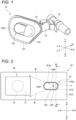
- FIG. 1 illustrates an appearance of a cleaning device 10 according to a first embodiment.
- the cleaning device 10 is a device adapted to be attached to a support 61 to clean a lighting device 70.
- the lighting device 70 may be a headlamp device adapted to be installed in a vehicle 80 illustrated in FIG. 3 .
- the support 61 may be a component constituting a part of the vehicle 80.
- the vehicle 80 is an example of a mobility.
- the lighting device 70 includes a translucent cover 71.
- the translucent cover 71 defines a lamp chamber accommodating a light source 72, and allows passage of light emitted from the light source 72.
- the cleaning device 10 includes a nozzle 11.
- the cleaning device 10 is configured to perform cleaning by jetting cleaning liquid W from the nozzle 11 toward the translucent cover 71.
- the translucent cover 71 is an example of a target.
- the cleaning liquid W is an example of fluid.
- FIG. 4 illustrates a cross section along the line IV-IV in FIG. 2 and viewed from the arrowed direction.
- the cleaning device 10 includes a joint 12. One end of a supply pipe (not illustrated) of the cleaning liquid W is connected to the joint 12.
- the joint 12 includes a channel 121 adapted to be communicated with the supply pipe.
- the nozzle 11 includes an outlet 111 and a channel 112.
- the channel 112 communicates with the outlet 111.
- the channel 112 and the channel 121 communicate with each other.
- a channel for the cleaning liquid W extending from the supply pipe to the outlet 111 is formed.
- the cleaning liquid W is jetted from the outlet 111.
- the cleaning device 10 includes a bracket 13.
- the bracket 13 is configured to hold the nozzle 11 in place. In other words, the position of the nozzle 11 in the cleaning device 10 is unchanged and is distinguished from a cleaning device with a so-called pop-up nozzle.
- the cleaning device 10 includes an adhesive portion 14. As illustrated in FIG. 4 , the adhesive portion 14 adheres the bracket 13 to an inner face 611 of the support 61. In other words, the cleaning device 10 is attached to the support 61 from the side corresponding to the inner face 611.
- the adhesive portion 14 is implemented by a tape member having an adhesive layer on both faces thereof.
- One adhesive layer in the tape member is adhered to a supported face 131 of the bracket 13.
- the other adhesive layer is adhered to the inner face 611 of the support 61.
- the adhesive portion 14 may be implemented by adhesive agent applied when the cleaning device 10 is attached to the support 61.
- the bracket 13 includes a guide 132 and a cover 133.
- an opening 612 is formed in the support 61.
- the guide 132 and the cover 133 are exposed on the side corresponding to an outer face 613 of the support 61 through the opening 612.
- the guide 132 has a recessed face 132a.
- the recessed face 132a has a dimension and a shape capable of guiding the cleaning liquid W jetted from the nozzle 11 to the translucent cover 71.
- the cover 133 is formed so as to cover at least a portion of the nozzle 11 when viewed from a side corresponding to the outer face 613 of the support 61.
- an outer edge 132b of the guide 132 and the outer edge 133a of the cover 133 are located inside an inner edge 612a of the opening 612.
- FIG. 5 illustrates a bracket of a cleaning device according to a comparative example.
- the bracket includes a cover 133'.
- the cover 133' is disposed so as to cover a nozzle located below.
- the cover 133' includes an engaging portion 134'.
- the engaging portion 134' secures the bracket to the support 61 by engaging the inner edge 612a of the opening 612 of the support 61 so as to clamp from the thickness direction of the support 61.
- an outer edge 133a' of the cover 133' must be located outside the inner edge 612a of the opening 612. Since the dimension of the portion exposed on the side corresponding to the outer face 613 of the support 61 is increased by the corresponding amount, the visibility of the cleaning device is enhanced.
- the cover 133' must be inserted through the opening 612 from the side corresponding to the outer face 613. Accordingly, in order to couple the bracket 13' to the nozzle, it is necessary to perform work from both the side corresponding to the inner face 611 and the side corresponding to the outer face 613 of the support 61.
- the bracket 13 and the inner face 611 are adhered by the adhesive portion 14 with a simple operation of causing the guide 132 and the cover 133 to pass through the opening 612 from the side corresponding to the inner face 611 of the support 61, so that the cleaning device 10 can be attached to the support 61. Since it is possible to eliminate the need for work from the side corresponding to the outer face 613 of the support 61, it is possible to simplify the production equipment and improve the productivity.
- FIG. 6 illustrates an appearance of a cleaning device 20 according to a second embodiment.
- the cleaning device 20 is a device adapted to be attached to a support 62 to clean a lighting device 70.
- the support 62 may be a component constituting a part of the vehicle 80 illustrated in FIG. 3 .
- the cleaning device 20 includes a nozzle 21.
- the cleaning device 20 is configured to perform cleaning by jetting cleaning liquid W from the nozzle 21 toward the translucent cover 71.
- FIG. 8 illustrates a cross section along the line VIII-VIII in FIG. 6 as viewed from the arrowed direction.
- the cleaning device 20 includes a joint 22.
- One end of a supply pipe (not illustrated) of the cleaning liquid W is connected to the joint 22.
- the joint 22 includes a channel 221 adapted to be communicated with the supply pipe.
- the nozzle 21 includes an outlet 211 and a channel 212.
- the channel 212 communicates with the outlet 211.
- the channel 212 and the channel 221 communicate with each other.
- a channel for the cleaning liquid W extending from the supply pipe to the outlet 211 is formed.
- the cleaning liquid W is jetted from the outlet 211.
- the cleaning device 20 includes a bracket 23.
- the bracket 23 is configured to hold the nozzle 21 in place. In other words, the position of the nozzle 21 in the cleaning device 20 is unchanged, and is distinguished from a cleaning device with a so-called pop-up nozzle.
- the cleaning device 20 includes an adhesive portion 24. As illustrated in FIG. 8 , the adhesive portion 24 adheres the bracket 23 to an inner face 621 of the support 62. In other words, the cleaning device 20 is attached to the support 62 from the side corresponding to the inner face 621.
- the adhesive portion 24 is implemented by a tape member having an adhesive layer on both faces thereof.
- One adhesive layer in the tape member is adhered to a supported face 231 of the bracket 23.
- the other adhesive layer is adhered to the inner face 621 of the support 62.
- the adhesive portion 24 may be implemented by adhesive agent applied when the cleaning device 20 is attached to the support 62.
- the bracket 23 includes a guide 232.
- the guide 232 has a recessed face 232a.
- the recessed face 232a has a dimension and a shape capable of guiding the cleaning liquid W jetted from the nozzle 21 to the translucent cover 71.
- an opening 622 is formed in the support 62.
- the guide 232 is exposed to the side corresponding to an outer face 623 of the support 62 through the opening 622.
- an outer edge 232b of the guide 232 is located inside an inner edge 622a of the opening 622.
- the nozzle 21 is disposed such that at least a portion thereof is covered by the support 62 when viewed from a side corresponding to the outer face 623 of the support 62.
- the bracket 23 and the inner face 621 are adhered by the adhesive portion 24 with a simple operation of causing the opening 622 to pass through from the side corresponding to the inner face 621 of the support 62, so that the cleaning device 20 can be attached to the support 62. Since it is possible to eliminate the need for work from the side corresponding to the outer face 623 of the support 62, it is possible to simplify the production equipment and improve the productivity.
- the nozzle 21 is covered by the support 62 itself when viewed from the side corresponding to the outer face 623 of the support 62, it is possible to reduce the dimension of the portion exposed on the side corresponding to the outer face 623 through the opening 622 in the bracket 23. Accordingly, it is possible to reduce the visibility of the cleaning device 20.
- the guide 232 may include a deflector 232c.
- the deflector 232c is formed as a wall capable of deflecting the traveling direction of the cleaning liquid W jetted from the nozzle 21 toward the translucent cover 71.
- An arrow indicated with a chain line in FIG. 7 represents a path of the cleaning liquid W assumed when the deflector 232c is not present. It is conceivable that the cleaning liquid W that is not deflected by the deflector 232c is consumed without contributing to the cleaning of the translucent cover 71. By providing the deflector 232c as in this example, it is possible to improve the utilization efficiency of the cleaning liquid W.
- a similar deflector may be formed on the guide 132 of the bracket 13 of the cleaning device 10 according to the first embodiment.
- FIG. 9 illustrates an appearance of a cleaning device 30 according to a third embodiment.
- the cleaning device 30 is a device adapted to be attached to a support 63 to clean the lighting device 70.
- the support 63 may be a component constituting a part of the vehicle 80 illustrated in FIG. 3 .
- the cleaning device 30 includes a nozzle 31.
- the cleaning device 30 is configured to perform cleaning by jetting cleaning liquid W from the nozzle 31 toward the translucent cover 71.
- FIG. 11 illustrates a cross section along the line XI-XI in FIG. 10 and viewed from the arrowed direction.
- the cleaning device 30 includes a joint 32. One end of a supply pipe (not illustrated) of the cleaning liquid W is connected to the joint 32.
- the joint 32 includes a channel 321 adapted to be communicated with the supply pipe.
- the nozzle 31 includes an outlet 311 and a channel 312.
- the channel 312 communicates with the outlet 311.
- the channel 312 and the channel 321 communicate with each other.
- a channel for the cleaning liquid W extending from the supply pipe to the outlet 311 is formed.
- the cleaning liquid W is jetted from the outlet 311.
- the cleaning device 30 includes a bracket 33.
- the bracket 33 is configured to hold the nozzle 31 in place. In other words, the position of the nozzle 31 in the cleaning device 30 is unchanged, and is distinguished from a cleaning device with a so-called pop-up nozzle.
- the cleaning device 30 includes an adhesive portion 34. As illustrated in FIG. 11 , the adhesive portion 34 adheres the bracket 33 to an inner face 631 of the support 63. In other words, the cleaning device 30 is attached to the support 63 from the side corresponding to the inner face 631.
- the adhesive portion 34 is implemented by a tape member having an adhesive layer on both faces thereof.
- One adhesive layer in the tape member is adhered to a supported face 331 of the bracket 33.
- the other adhesive layer is adhered to the inner face 631 of the support 63.
- the adhesive portion 34 may be implemented by adhesive agent applied when the cleaning device 30 is attached to the support 63.
- the support 63 has a recessed face 634.
- the recessed face 634 is formed as a face continuous with an outer face 633 of the support 63 and recessed to the side corresponding to the inner face 631 relative to the outer face 633.
- the bracket 33 of the cleaning device 30 has an opening 332.
- the opening 332 has a shape and a dimension capable of receiving the recessed face 634 when the cleaning device 30 is attached to the support 63.
- the nozzle 31 is disposed so that at least a portion thereof is covered by the support 63 when viewed from the side corresponding to the outer face 633 of the support 63.
- the arrangement of the nozzle 31 is determined so that the jetted cleaning liquid W can be guided to the translucent cover 71 of the lighting device 70 by the recessed face 634 of the support 63.
- the bracket 33 since the bracket 33 has the opening 332 for receiving the recessed face 634 of the support 63 on the side corresponding to the inner face 631 of the support 63, the bracket 33 and the inner face 631 are adhered by the adhesive portion 34 with a simple operation of causing the opening 332 to receive the recessed face 634 from the side corresponding to the inner face 631 of the support 63, so that the cleaning device 30 can be attached to the support 63. Since it is possible to eliminate the need for work from the side corresponding to the outer face 633 of the support 63, it is possible to simplify the production equipment and improve the productivity.
- bracket 43 it is possible to make difficult to view the bracket 43 from the side corresponding to the outer face 633 of the support 63. Coupled with the appearance that at least a portion of the nozzle 31 is covered by the support 63 itself when viewed from the side corresponding to the outer face 633 of the support 63, the visibility of the cleaning device 30 can be reduced.
- the arrangement of the nozzle 31 may be determined so that the jetted cleaning liquid W is deflected toward the translucent cover 71 by a part of the recessed face 634.
- An arrow indicated with a chain line in FIG. 10 represents a path of the cleaning liquid W assumed when the cleaning liquid W is not subjected to the deflection by the recessed face 634. It is conceivable that the cleaning liquid W that is not deflected by the recessed face 634 is consumed without contributing to the cleaning of the translucent cover 71.
- FIG. 12 illustrates an appearance of a cleaning device 40 according to a fourth embodiment.
- the cleaning device 40 is a device adapted to be attached to a support 64 to clean the lighting device 70.
- the support 64 may be a component constituting a part of the vehicle 80 illustrated in FIG. 3 .
- the cleaning device 40 includes a nozzle 41.
- the cleaning device 40 is configured to perform cleaning by jetting cleaning liquid W from the nozzle 41 toward the translucent cover 71.
- FIG. 14 illustrates a cross section along the line XIV-XIV in FIG. 13 and viewed from the arrowed direction.
- the cleaning device 40 includes a joint 42.
- One end of a supply pipe (not illustrated) of the cleaning liquid W is connected to the joint 42.
- the joint 42 includes a channel 421 adapted to be communicated with the supply pipe.
- the nozzle 41 includes an outlet 411 and a channel 412.
- the channel 412 communicates with the outlet 411.
- the channel 412 and the channel 421 communicate with each other.
- a channel for the cleaning liquid W extending from the supply pipe to the outlet 411 is formed.
- the cleaning liquid W is jetted from the outlet 411.
- the support 64 includes a bracket portion 640.
- the bracket portion 640 extends from an inner face 641 of the support 64 so as to have a hollowed cylindrical shape.
- the cleaning device 40 includes an engaging portion 44.
- the engaging portion 44 is configured to engage with the bracket portion 640 to hold the nozzle 41 in place relative to the bracket portion 640.
- the engaging portion 44 may be implemented by a well-known snap-fit structure or the like.
- the cleaning device 40 is attached to the support 64 from the side corresponding to the inner face 641.
- the position of the nozzle 41 in the cleaning device 40 is unchanged and is distinguished from a cleaning device with a so-called pop-up nozzle.
- the support 64 has a recessed face 644.
- the recessed face 644 is formed as a face continuous with the outer face 643 of the support 64 and recessed to the side corresponding to the inner face 641 relative to the outer face 643.
- the recessed face 644 communicates with an inner circumferential face of the bracket portion 640.
- the nozzle 41 is disposed such that at least a portion thereof is covered by the support 64 when viewed from a side corresponding to the outer face 643 of the support 64.
- the arrangement of the nozzle 41 is determined so that the jetted cleaning liquid W can be guided to the translucent cover 71 of the lighting device 70 by the recessed face 644 of the support 64.
- the cleaning device 40 can be attached to the support 64 with a simple operation of engaging the nozzle 41 with the support 64 from the side corresponding to the inner face 641 of the support 64 with the use of the engaging portion 44. Since it is possible to eliminate the need for work from the side corresponding to the outer face 643 of the support 64, it is possible to simplify the production equipment and improve the productivity.
- the arrangement of the nozzle 41 may be determined so that the jetted cleaning liquid W is deflected toward the translucent cover 71 by a part of the recessed face 644.
- An arrow indicated with a chain line in FIG. 13 represents a path of the cleaning liquid W assumed when the cleaning liquid W is not subjected to the deflection by the recessed face 644. It is conceivable that the cleaning liquid W that is not deflected by the recessed face 644 is consumed without contributing to the cleaning of the translucent cover 71.
- FIG. 15 illustrates an appearance of a cleaning device 50 according to a fifth embodiment.
- the cleaning device 50 is a device adapted to be attached to a support 65 to clean the lighting device 70.
- the support 65 may be a component constituting a part of the vehicle 80 illustrated in FIG. 3 .
- the cleaning device 50 includes a nozzle 51.
- the cleaning device 50 is configured to perform cleaning by jetting cleaning liquid W from the nozzle 51 toward the translucent cover 71.
- FIG. 17 illustrates a cross section along the line XVII-XVII in FIG. 16 and viewed from the arrowed direction.
- the cleaning device 50 includes a joint 52.
- One end of a supply pipe (not illustrated) of the cleaning liquid W is connected to the joint 52.
- the joint 52 includes a channel 521 adapted to be communicated with the supply pipe.
- the nozzle 51 includes an outlet 511 and a channel 512.
- the channel 512 communicates with the outlet 511.
- the channel 512 and the channel 521 communicate with each other.
- a channel for the cleaning liquid W extending from the supply pipe to the outlet 511 is formed.
- the cleaning liquid W is jetted from the outlet 511.
- the cleaning device 50 includes a bracket 53.
- the bracket 53 is configured to hold the nozzle 51 in place. In other words, the position of the nozzle 51 in the cleaning device 50 is unchanged, and is distinguished from a cleaning device with a so-called pop-up nozzle.
- the cleaning device 50 includes an adhesive portion 54.
- the adhesive portion 54 adheres the bracket 53 to an inner face 651 of the support 65.
- the cleaning device 50 is attached to the support 65 from the side corresponding to the inner face 651.
- the adhesive portion 54 is implemented by a tape member having an adhesive layer on both faces thereof.
- One adhesive layer in the tape member is adhered to a supported face 531 of the bracket 53.
- the other adhesive layer is adhered to the inner face 651 of the support 65.
- the adhesive portion 54 may be implemented by adhesive agent applied when the cleaning device 50 is attached to the support 65.
- the support 65 has an opening 652.
- the opening 652 is formed so as to be adjacent to the translucent cover 71 of the lighting device 70.
- the nozzle 51 is disposed so that the cleaning liquid W is jetted to the translucent cover 71 through the opening 652.
- the nozzle 51 is disposed so that at least a portion thereof is covered by the support 65 when viewed from a side corresponding to an outer face 653 of the support 65.
- the opening 652 is formed such that an inner edge 652a faces the translucent cover 71. In other words, there is no object that blocks the cleaning liquid W between the inner edge 652a and the translucent cover 71.
- the bracket 53 and the inner face 651 are adhered by the adhesive portion 54 with a simple operation of pressing the bracket 53 against the support 65 from the side corresponding to the inner face 651 of the support 65, so that the cleaning device 50 can be attached to the support 65. Since the work from the side corresponding to the outer face 653 of the support 65 can be eliminated, it is possible to simplify the production equipment and improve the productivity.
- the translucent cover 71 of the lighting device 70 and the nozzle 51 can be directly faced each other through the opening 652 of the support 65, the flexibility as for the locational relationship therebetween can be increased.
- bracket 43 it is possible to make difficult to view the bracket 43 from the side corresponding to the outer face 633 of the support 65. Coupled with the appearance that at least a portion of the nozzle 51 is covered by the support 65 itself when viewed from the side corresponding to the outer face 653 of the support 65, the visibility of the cleaning device 50 can be reduced.
- FIG. 18 illustrates an appearance of a cleaning device 90 according to a sixth embodiment as viewed from the front side.
- the cleaning device 90 is a device adapted to be attached to a support 69 to clean the lighting device 70.
- the support 69 may be a component constituting a part of the vehicle 80 illustrated in FIG. 3 .
- the cleaning device 90 includes a nozzle 91.
- the cleaning device 90 is configured to perform cleaning by jetting cleaning liquid W from the nozzle 91 toward the translucent cover 71.
- FIG. 20 illustrates a cross section along the line XX-XX in FIG. 19 and viewed from the arrowed direction.
- the cleaning device 90 includes a joint 92.
- One end of a supply pipe (not illustrated) of the cleaning liquid W is connected to the joint 92.
- the joint 92 includes a channel adapted to be communicated with the supply pipe.
- the nozzle 91 includes an outlet 911 and a channel.
- the channel communicates with the outlet 911.
- the channels communicate with each other.
- a channel for the cleaning liquid W extending from the supply pipe to the outlet 911 is formed.
- the cleaning liquid W is jetted from the outlet 911.
- the cleaning device 90 includes a bracket 93.
- the bracket 93 is configured to hold the nozzle 91 in place. In other words, the position of the nozzle 91 in the cleaning device 90 is unchanged, and is distinguished from a cleaning device with a so-called pop-up nozzle.
- the cleaning device 90 includes an adhesive portion 94. As illustrated in FIG. 20 , the adhesive portion 94 adheres the bracket 93 to an inner face 691 of the support 69. In other words, the cleaning device 90 is attached to the support 69 from the side corresponding to the inner face 691.
- the adhesive portion 94 is implemented by a tape member having an adhesive layer on both faces thereof.
- One adhesive layer in the tape member is adhered to a supported face 931 of the bracket 93.
- the other adhesive layer is adhered to the inner face 691 of the support 69.
- the adhesive portion 94 may be implemented by adhesive agent applied when the cleaning device 90 is attached to the support 69.
- the bracket 93 includes a guide 932 and a cover 933.
- an opening 692 is formed in the support 69.
- the guide 932 and the cover 933 are exposed on the side corresponding to an outer face 693 of the support 69 through the opening 692.
- the guide 932 has a recessed face 932a.
- the recessed face 932a has a dimension and a shape capable of guiding the cleaning liquid W jetted from the nozzle 91 to the translucent cover 71.
- the cover 933 is formed so as to cover at least a portion of the nozzle 91 when viewed from a side corresponding to the outer face 693 of the support 69.
- an outer edge 932b of the guide 932 and an outer edge 933a of the cover 933 are located inside an inner edge 692a of the opening 692. Accordingly, the bracket 93 and the inner face 691 are adhered to by the adhesive portion 94 with a simple operation of causing the guide 932 and the cover 933 to pass through the opening 692 from the side corresponding to the inner face 691 of the support 69, so that the cleaning device 90 can be attached to the support 69. Since it is possible to eliminate the need for work from the side corresponding to the outer face 693 of the support 69, it is possible to simplify the production equipment and improve the productivity.
- the bracket 93 is formed with multiple apertures 934.
- Each aperture 934 is a through hole having a dimension that allows passage of the cleaning liquid W.
- Each aperture 934 communicates a side of the bracket 93 facing an outer side of the support 69 and a side of the bracket 93 facing an inner side of the support 69.
- Each aperture 934 is disposed so as to be covered by the support 69 when the cleaning device 90 is attached to the support 69.
- An aperture 934a that is one of the multiple apertures 934, is disposed such that at least a portion thereof is located vertically under the nozzle 91.
- a portion of the cleaning liquid W jetted toward the translucent cover 71 of the lighting device 70 may descend along the outer face 693 of the support 69 and enter the opening 692.
- Such cleaning liquid as returned may include dust and mud peeled from the translucent cover 71 by the cleaning. Since the apertures 934 as described above are formed in the bracket 93, it is possible to promote drain of the cleaning liquid that has returned and entered the opening 692. As a result, it is possible to suppress occurrence of a situation that the jetting of the cleaning liquid W from the nozzle 91 is obstructed by dust and/or mud that have entered the opening 692 together with the returned cleaning liquid and fixed to the guide 932 while being dried.
- each aperture 934 is disposed so as to be covered by the support 69, it is possible to reduce the visibility from the side corresponding to the outer face 693 of the support 69. Accordingly, it is possible to suppress the influence of the configuration for draining the cleaning liquid that has returned and entered the opening 692 on the appearance of the cleaning device 90.
- the number of the apertures 934 can be appropriately determined as long as at least one aperture 934 is located vertically under the nozzle 91 (in other words, at a location where the drain efficiency is the highest).
- the guide 932 may include a deflector 932c.
- the deflector 932c is formed as a wall capable of deflecting the traveling direction of the cleaning liquid W jetted from the nozzle 91 toward the translucent cover 71.
- An arrow indicated by a chain line in FIG. 19 represents a path of the cleaning liquid W assumed when the deflector 932c is not present. It is conceivable that the cleaning liquid W that is not deflected by the deflector 932c is consumed without contributing to the cleaning of the translucent cover 71. By providing the deflector 932c as in this example, it is possible to improve the utilization efficiency of the cleaning liquid W.
- FIG. 21 illustrates the appearance of the cleaning device 90 as viewed from the direction along the arrow XXI in FIG. 20 .
- the deflector 932c is formed with multiple apertures 935.
- Each aperture 935 faces the recessed face 932a of the guide 932.
- Each aperture 935 is a through hole having a dimension that allows passage of the cleaning liquid W.
- Each aperture 935 communicates a side of the bracket 93 facing an outer side of the support 69 and a side of the bracket 93 facing an inner side of the support 69.
- each aperture 935 is formed at a position where is difficult to be visually recognized in the front view of the cleaning device 90, it is possible to suppress the configuration for draining the returned cleaning liquid on the appearance of the cleaning device 90.
- two apertures 935 are formed.
- the number of the apertures 935 may be appropriately determined. In a case where only one aperture 935 is formed, it is preferable that the opening is disposed below the nozzle 91 at a position facing the recessed face 932a. In a case where the aperture 935 is formed, the aperture 934 described above may be omitted.
- At least one of the aperture 934 and the aperture 935 of the cleaning device 90 according to the sixth embodiment may be formed in each of the bracket 13 of the cleaning device 10 according to the first embodiment, the bracket 23 of the cleaning device 20 according to the second embodiment, and the bracket 33 of the cleaning device 30 according to the third embodiment.
- the target to be cleaned by the cleaning device is not limited to the translucent cover 71 of the lighting device 70.
- Examples of other targets include a sensing face of a sensor that senses information around the vehicle 80 with light, or a surface of a member through which such light passes.
- liquid such as water or gas such as air
- the liquid or gas is an example of the fluid.
- the cleaning device according to each embodiment may be installed in a mobility other than the vehicle.
- Examples of other mobilities include an aircraft, a flying object, a ship, and the like.
- the mobility may not require a driver.
- the cleaning device according to each embodiment does not have to be installed in a mobility.
- the cleaning device according to each embodiment may be installed in a house, a facility, a transportation infrastructure, or the like and used for cleaning the target as exemplified above.
Landscapes
- Engineering & Computer Science (AREA)
- Mechanical Engineering (AREA)
- Water Supply & Treatment (AREA)
- Nozzles (AREA)
- Details Or Accessories Of Spraying Plant Or Apparatus (AREA)
Abstract
A cleaning device (10) is adapted to be attached to a support (61) having an opening (612). A nozzle (11) is configured to jet cleaning liquid (W) toward a translucent cover (71) of a lighting device (70). A bracket holds the nozzle (11) in place. An adhesive portion adheres the bracket to an inner face of the support (61). The bracket includes a guide (132) and a cover (133). The guide (132) has a recessed face (132a) configured to guide the cleaning liquid (W) toward the translucent cover (71). The cover (133) at least partially covers the nozzle (11) as viewed from a side corresponding to an outer face (613) of the support (61). An outer edge (132b) of the guide (132) and an outer edge (133a) of the cover (133) are located inside an inner edge (612a) of the opening (612) when the cleaning device (10) is attached to the support (61).
Description
- The present disclosure relates to a cleaning device adapted to be attached to a support having an opening or a recessed face.
-
Patent Document 1 discloses a cleaning device adapted to be attached to a support provided as a part of a vehicle that is an example of a mobility. The cleaning device includes a nozzle for jetting cleaning liquid, that is an example of fluid, to clean a headlamp. While the cleaning liquid is not jetted, the nozzle is obscured by a part of the support. When the cleaning liquid is jetted, the part of the support is displaced to expose the nozzle. - Patent Document 1:
Japanese Patent Publication No. 2019-156210 A - It is demanded to reduce the visibility of such a cleaning device.
- A first illustrative aspect of the presently disclosed subject matter provides a cleaning device adapted to be attached to a support having an opening, the cleaning device comprising:
- a nozzle configured to jet fluid toward a target;
- a bracket holding the nozzle in place; and
- an adhesive portion adhering the bracket to an inner face of the support,
- wherein the bracket includes:
- a guide having a recessed face that is configured to guide the fluid toward the target; and
- a cover at least partially covering the nozzle as viewed from a side corresponding to an outer face of the support; and
- wherein an outer edge of the guide and an outer edge of the cover are configured to be located inside an inner edge of the opening when the cleaning device is attached to the support.
- According to the configuration of the first illustrative aspect, since the outer edge of the guide of the bracket and the outer edge of the cover are located inside the inner edge of the opening, the bracket and the inner face are adhered by the adhesive portion with a simple operation of causing the guide and the cover to pass through the opening from a side corresponding to the inner face of the support, so that the cleaning device can be attached to the support. Since it is possible to eliminate the need for work from a side corresponding to the outer face of the support, it is possible to simplify the production equipment and improve the productivity.
- In addition, it is possible to reduce the dimension of a portion of the bracket that is exposed through the opening on the side corresponding to the outer face of the support. Coupled with the appearance that at least a portion of the nozzle is covered by the cover when viewed from the side corresponding to the outer face, the visibility of the cleaning device can be reduced.
- A second illustrative aspect of the presently disclosed subject matter provides a cleaning device adapted to be attached to a support having an opening, the cleaning device comprising:
- a nozzle configured to jet fluid toward a target;
- a bracket holding the nozzle in place; and
- an adhesive portion adhering the bracket to an inner face of the support,
- wherein the bracket includes a guide having a recessed face that is configured to guide the fluid toward the target;
- wherein the nozzle is disposed so as to be at least partially covered by the support when the cleaning device is attached to the support; and
- wherein an outer edge of the guide is configured to be located inside an inner edge of the opening when the cleaning device is attached to the support.
- According to the configuration of the second illustrative aspect, since the outer edge of the guide of the bracket is located inside the inner edge of the opening, the bracket and the inner face are adhered by the adhesive portion with a simple operation of causing the opening to pass through the guide from a side corresponding to the inner face of the support, so that the cleaning device can be attached to the support. Since it is possible to eliminate the need for work from a side corresponding to the outer face of the support, it is possible to simplify the production equipment and improve the productivity.
- In addition, since at least a portion of the nozzle is covered by the support itself when viewed from the side corresponding to the outer face of the support, it is possible to reduce the dimension of the portion exposed to the side corresponding to the outer face through the opening in the bracket. Accordingly, it is possible to reduce the visibility of the cleaning device.
- A third illustrative aspect of the presently disclosed subject matter provides a cleaning device adapted to be attached to a support having a recessed face, the cleaning device comprising:
- a nozzle configured to jet fluid toward a target;
- a bracket holding the nozzle in place; and
- an adhesive portion adhering the bracket to an inner face of the support,
- wherein the bracket includes an opening configured to receive the recessed face at a side corresponding to the inner face of the support;
- wherein the nozzle is disposed such that the fluid is guided toward the target by the recessed face when the cleaning device is attached to the support; and
- wherein the nozzle is disposed so as to be at least partially covered by the support as viewed from a side corresponding to an outer face of the support when the cleaning device is attached to the support.
- According to the configuration of the third illustrative aspect, since the bracket has the opening for receiving the recessed face of the support on the side corresponding to the inner face of the support, the bracket and the inner face are adhered by the adhesive portion with a simple operation of causing the opening to receive the recessed face from the side corresponding to the inner face of the support, so that the cleaning device can be attached to the support. Since it is possible to eliminate the need for work from a side corresponding to the outer face of the support, it is possible to simplify the production equipment and improve the productivity.
- In addition, it is possible to make difficult to view the bracket from the side corresponding to the outer face of the support. Coupled with the appearance that at least a portion of the nozzle is covered by the support itself when viewed from the side corresponding to the outer face of the support, the visibility of the cleaning device can be reduced.
- A fourth illustrative aspect of the presently disclosed subject matter provides a cleaning device adapted to be attached to a support having a recessed face, the cleaning device comprising:
- a nozzle configured to jet fluid toward a target; and
- an engaging portion configured to engage with the support at a side corresponding to an inner face of the support to hold the nozzle in place,
- wherein the nozzle is disposed such that the fluid is guided toward the target by the recessed face when the cleaning device is attached to the support; and
- wherein the nozzle is disposed so as to be at least partially covered by the support as viewed from a side corresponding to an outer face of the support when the cleaning device is attached to the support.
- According to the configuration of the fourth illustrative aspect, the cleaning device can be attached to the support with a simple operation of engaging the nozzle with the support from a side corresponding to the inner face of the support with the use of the engaging portion. Since it is possible to eliminate the need for work from a side corresponding to the outer face of the support, it is possible to simplify the production equipment and improve the productivity.
- In addition, since it is possible to make it difficult to view the nozzle from the side corresponding to the outer face of the support, the visibility of the cleaning device can be reduced.
- A fifth illustrative aspect of the presently disclosed subject matter provides a cleaning device adapted to be attached to a support having an opening, the cleaning device comprising:
- a nozzle configured to jet fluid toward a target;
- a bracket holding the nozzle in place; and
- an adhesive portion adhering the bracket to an inner face of the support,
- wherein the nozzle is disposed such that the fluid that has passed the opening is jetted toward the target when the cleaning device is attached to the support; and
- wherein the nozzle is disposed so as to be at least partially covered by the support as viewed from a side corresponding to an outer face of the support when the cleaning device is attached to the support.
- According to the configuration of the fifth illustrative aspect, the bracket and the inner face are adhered by the adhesive portion with a simple operation of pressing the bracket against the support from a side corresponding to the inner face of the support, so that the cleaning device can be attached to the support. Since it is possible to eliminate the need for work from a side corresponding to the outer face of the support, it is possible to simplify the production equipment and improve the productivity.
- In addition, since the target and the nozzle can be directly faced each other through the opening of the support, the flexibility as for the locational relationship therebetween can be increased.
- In addition, it is possible to make difficult to view the bracket from the side corresponding to the outer face of the support. Coupled with the appearance that at least a portion of the nozzle is covered by the support itself when viewed from the side corresponding to the outer face of the support, the visibility of the cleaning device can be reduced.
-
-
FIG. 1 illustrates an appearance of a cleaning device according to a first embodiment. -
FIG. 2 illustrates a state that the cleaning device ofFIG. 1 is attached to a support. -
FIG. 3 illustrates a vehicle in which the cleaning device ofFIG. 1 is to be installed. -
FIG. 4 illustrates a cross section viewed from an arrowed direction along a line IV-IV ofFIG. 2 . -
FIG. 5 illustrates a cleaning device according to a comparative example. -
FIG. 6 illustrates an appearance of a cleaning device according to a second embodiment. -
FIG. 7 illustrates a state that the cleaning device ofFIG. 6 is attached to a support. -
FIG. 8 illustrates a cross section viewed from an arrowed direction along a line VIII-VIII ofFIG. 7 . -
FIG. 9 illustrates an appearance of a cleaning device according to a third embodiment. -
FIG. 10 illustrates a state that the cleaning device ofFIG. 9 is attached to a support. -
FIG. 11 illustrates a cross section viewed from an arrowed direction along a line XI-XI ofFIG. 10 . -
FIG. 12 illustrates an appearance of a cleaning device according to a fourth embodiment. -
FIG. 13 illustrates a state that the cleaning device ofFIG. 12 is attached to a support. -
FIG. 14 illustrates a cross section viewed from an arrowed direction along a line XIV-XIV ofFIG. 13 . -
FIG. 15 illustrates an appearance of a cleaning device according to a fifth embodiment. -
FIG. 16 illustrates a state that the cleaning device ofFIG. 15 is attached to a support. -
FIG. 17 illustrates a cross section viewed from an arrowed direction along a line XVII-XVII ofFIG. 16 . -
FIG. 18 illustrates an appearance of a cleaning device according to a sixth embodiment. -
FIG. 19 illustrates a state that the cleaning device ofFIG. 18 is attached to a support. -
FIG. 20 illustrates a cross section viewed from an arrowed direction along a line XX-XX ofFIG. 19 . -
FIG. 21 illustrates an appearance of the cleaning device as viewed from a direction along an arrow XXI ofFIG. 20 . - Exemplary embodiments will be described below in detail with reference to the accompanying drawings. In each of the drawings used in the following descriptions, the scale is changed as required in order to make each member have a recognizable size.
- In the accompanying drawings, an arrow F represents a forward direction of the illustrated structure. An arrow B represents a rearward direction of the illustrated structure. An arrow U represents an upward direction of the illustrated structure. An arrow D represents a downward direction of the illustrated structure. An arrow R represents a rightward direction of the illustrated structure. An arrow L represents a leftward direction of the illustrated structure. The expression according to these directions is intended to be used for convenience of explanation and is not intended to limit the attitude of the structure at the time of actual use.
-
FIG. 1 illustrates an appearance of acleaning device 10 according to a first embodiment. As illustrated inFIG. 2 , thecleaning device 10 is a device adapted to be attached to asupport 61 to clean alighting device 70. For example, thelighting device 70 may be a headlamp device adapted to be installed in avehicle 80 illustrated inFIG. 3 . Thesupport 61 may be a component constituting a part of thevehicle 80. Thevehicle 80 is an example of a mobility. - As illustrated in
FIG. 2 , thelighting device 70 includes atranslucent cover 71. Thetranslucent cover 71 defines a lamp chamber accommodating alight source 72, and allows passage of light emitted from thelight source 72. Thecleaning device 10 includes anozzle 11. Thecleaning device 10 is configured to perform cleaning by jetting cleaning liquid W from thenozzle 11 toward thetranslucent cover 71. Thetranslucent cover 71 is an example of a target. The cleaning liquid W is an example of fluid. -
FIG. 4 illustrates a cross section along the line IV-IV inFIG. 2 and viewed from the arrowed direction. Thecleaning device 10 includes a joint 12. One end of a supply pipe (not illustrated) of the cleaning liquid W is connected to the joint 12. The joint 12 includes achannel 121 adapted to be communicated with the supply pipe. - On the other hand, the
nozzle 11 includes an outlet 111 and achannel 112. Thechannel 112 communicates with the outlet 111. As thenozzle 11 is connected to the joint 12, thechannel 112 and thechannel 121 communicate with each other. As a result, a channel for the cleaning liquid W extending from the supply pipe to the outlet 111 is formed. The cleaning liquid W is jetted from the outlet 111. - The
cleaning device 10 includes abracket 13. Thebracket 13 is configured to hold thenozzle 11 in place. In other words, the position of thenozzle 11 in thecleaning device 10 is unchanged and is distinguished from a cleaning device with a so-called pop-up nozzle. - As illustrated in
FIG. 1 , thecleaning device 10 includes anadhesive portion 14. As illustrated inFIG. 4 , theadhesive portion 14 adheres thebracket 13 to aninner face 611 of thesupport 61. In other words, thecleaning device 10 is attached to thesupport 61 from the side corresponding to theinner face 611. - In this example, the
adhesive portion 14 is implemented by a tape member having an adhesive layer on both faces thereof. One adhesive layer in the tape member is adhered to a supportedface 131 of thebracket 13. The other adhesive layer is adhered to theinner face 611 of thesupport 61. - It should be noted that the
adhesive portion 14 may be implemented by adhesive agent applied when thecleaning device 10 is attached to thesupport 61. - As illustrated in
FIG. 1 , thebracket 13 includes aguide 132 and acover 133. On the other hand, as illustrated inFIGS. 2 and4 , anopening 612 is formed in thesupport 61. As thecleaning device 10 is attached to thesupport 61, theguide 132 and thecover 133 are exposed on the side corresponding to anouter face 613 of thesupport 61 through theopening 612. - As illustrated in
FIGS. 1 and 2 , theguide 132 has a recessedface 132a. The recessedface 132a has a dimension and a shape capable of guiding the cleaning liquid W jetted from thenozzle 11 to thetranslucent cover 71. - The
cover 133 is formed so as to cover at least a portion of thenozzle 11 when viewed from a side corresponding to theouter face 613 of thesupport 61. - As illustrated in
FIGS. 2 and4 , anouter edge 132b of theguide 132 and theouter edge 133a of thecover 133 are located inside aninner edge 612a of theopening 612. -
FIG. 5 illustrates a bracket of a cleaning device according to a comparative example. The bracket includes a cover 133'. Although not illustrated, the cover 133' is disposed so as to cover a nozzle located below. - The cover 133' includes an engaging portion 134'. The engaging portion 134' secures the bracket to the
support 61 by engaging theinner edge 612a of theopening 612 of thesupport 61 so as to clamp from the thickness direction of thesupport 61. According to such a configuration, anouter edge 133a' of the cover 133' must be located outside theinner edge 612a of theopening 612. Since the dimension of the portion exposed on the side corresponding to theouter face 613 of thesupport 61 is increased by the corresponding amount, the visibility of the cleaning device is enhanced. - In addition, because of the structure thereof, the cover 133' must be inserted through the opening 612 from the side corresponding to the
outer face 613. Accordingly, in order to couple the bracket 13' to the nozzle, it is necessary to perform work from both the side corresponding to theinner face 611 and the side corresponding to theouter face 613 of thesupport 61. - On the other hand, in the configuration according to the present embodiment, since the
outer edge 132b of theguide 132 of thebracket 13 and theouter edge 133a of thecover 133 are located inside theinner edge 612a of theopening 612, thebracket 13 and theinner face 611 are adhered by theadhesive portion 14 with a simple operation of causing theguide 132 and thecover 133 to pass through the opening 612 from the side corresponding to theinner face 611 of thesupport 61, so that thecleaning device 10 can be attached to thesupport 61. Since it is possible to eliminate the need for work from the side corresponding to theouter face 613 of thesupport 61, it is possible to simplify the production equipment and improve the productivity. - In addition, it is possible to reduce the dimension of a portion of the
bracket 13 exposed on the side corresponding to theouter face 613 of thesupport 61 through theopening 612. Coupled with the appearance that at least a portion of thenozzle 11 is covered by thecover 133 when viewed from the side corresponding to theouter face 613, the visibility of thecleaning device 10 can be reduced. -
FIG. 6 illustrates an appearance of acleaning device 20 according to a second embodiment. As illustrated inFIG. 7 , thecleaning device 20 is a device adapted to be attached to asupport 62 to clean alighting device 70. Thesupport 62 may be a component constituting a part of thevehicle 80 illustrated inFIG. 3 . - As illustrated in
FIG. 7 , thecleaning device 20 includes anozzle 21. Thecleaning device 20 is configured to perform cleaning by jetting cleaning liquid W from thenozzle 21 toward thetranslucent cover 71. -
FIG. 8 illustrates a cross section along the line VIII-VIII inFIG. 6 as viewed from the arrowed direction. Thecleaning device 20 includes a joint 22. One end of a supply pipe (not illustrated) of the cleaning liquid W is connected to the joint 22. The joint 22 includes achannel 221 adapted to be communicated with the supply pipe. - On the other hand, the
nozzle 21 includes anoutlet 211 and achannel 212. Thechannel 212 communicates with theoutlet 211. As thenozzle 21 is connected to the joint 22, thechannel 212 and thechannel 221 communicate with each other. As a result, a channel for the cleaning liquid W extending from the supply pipe to theoutlet 211 is formed. The cleaning liquid W is jetted from theoutlet 211. - The
cleaning device 20 includes abracket 23. Thebracket 23 is configured to hold thenozzle 21 in place. In other words, the position of thenozzle 21 in thecleaning device 20 is unchanged, and is distinguished from a cleaning device with a so-called pop-up nozzle. - As illustrated in
FIG. 6 , thecleaning device 20 includes anadhesive portion 24. As illustrated inFIG. 8 , theadhesive portion 24 adheres thebracket 23 to aninner face 621 of thesupport 62. In other words, thecleaning device 20 is attached to thesupport 62 from the side corresponding to theinner face 621. - In this example, the
adhesive portion 24 is implemented by a tape member having an adhesive layer on both faces thereof. One adhesive layer in the tape member is adhered to a supportedface 231 of thebracket 23. The other adhesive layer is adhered to theinner face 621 of thesupport 62. - It should be noted that the
adhesive portion 24 may be implemented by adhesive agent applied when thecleaning device 20 is attached to thesupport 62. - As illustrated in
FIG. 6 , thebracket 23 includes aguide 232. Theguide 232 has a recessedface 232a. The recessedface 232a has a dimension and a shape capable of guiding the cleaning liquid W jetted from thenozzle 21 to thetranslucent cover 71. - On the other hand, as illustrated in
FIGS. 7 and8 , anopening 622 is formed in thesupport 62. As thecleaning device 20 is attached to thesupport 62, theguide 232 is exposed to the side corresponding to anouter face 623 of thesupport 62 through theopening 622. - At the same time, an
outer edge 232b of theguide 232 is located inside aninner edge 622a of theopening 622. Thenozzle 21 is disposed such that at least a portion thereof is covered by thesupport 62 when viewed from a side corresponding to theouter face 623 of thesupport 62. - In the configuration according to the present embodiment, since the
outer edge 232b of theguide 232 of thebracket 23 is located inside theinner edge 622a of theopening 622, thebracket 23 and theinner face 621 are adhered by theadhesive portion 24 with a simple operation of causing theopening 622 to pass through from the side corresponding to theinner face 621 of thesupport 62, so that thecleaning device 20 can be attached to thesupport 62. Since it is possible to eliminate the need for work from the side corresponding to theouter face 623 of thesupport 62, it is possible to simplify the production equipment and improve the productivity. - In addition, since at least a portion of the
nozzle 21 is covered by thesupport 62 itself when viewed from the side corresponding to theouter face 623 of thesupport 62, it is possible to reduce the dimension of the portion exposed on the side corresponding to theouter face 623 through theopening 622 in thebracket 23. Accordingly, it is possible to reduce the visibility of thecleaning device 20. - As illustrated in
FIGS. 6 and 7 , theguide 232 may include adeflector 232c. Thedeflector 232c is formed as a wall capable of deflecting the traveling direction of the cleaning liquid W jetted from thenozzle 21 toward thetranslucent cover 71. - An arrow indicated with a chain line in
FIG. 7 represents a path of the cleaning liquid W assumed when thedeflector 232c is not present. It is conceivable that the cleaning liquid W that is not deflected by thedeflector 232c is consumed without contributing to the cleaning of thetranslucent cover 71. By providing thedeflector 232c as in this example, it is possible to improve the utilization efficiency of the cleaning liquid W. - A similar deflector may be formed on the
guide 132 of thebracket 13 of thecleaning device 10 according to the first embodiment. -
FIG. 9 illustrates an appearance of acleaning device 30 according to a third embodiment. As illustrated inFIG. 10 , thecleaning device 30 is a device adapted to be attached to asupport 63 to clean thelighting device 70. Thesupport 63 may be a component constituting a part of thevehicle 80 illustrated inFIG. 3 . - As illustrated in
FIG. 10 , thecleaning device 30 includes anozzle 31. Thecleaning device 30 is configured to perform cleaning by jetting cleaning liquid W from thenozzle 31 toward thetranslucent cover 71. -
FIG. 11 illustrates a cross section along the line XI-XI inFIG. 10 and viewed from the arrowed direction. Thecleaning device 30 includes a joint 32. One end of a supply pipe (not illustrated) of the cleaning liquid W is connected to the joint 32. The joint 32 includes achannel 321 adapted to be communicated with the supply pipe. - On the other hand, the
nozzle 31 includes anoutlet 311 and achannel 312. Thechannel 312 communicates with theoutlet 311. As thenozzle 31 is connected to the joint 32, thechannel 312 and thechannel 321 communicate with each other. As a result, a channel for the cleaning liquid W extending from the supply pipe to theoutlet 311 is formed. The cleaning liquid W is jetted from theoutlet 311. - The
cleaning device 30 includes abracket 33. Thebracket 33 is configured to hold thenozzle 31 in place. In other words, the position of thenozzle 31 in thecleaning device 30 is unchanged, and is distinguished from a cleaning device with a so-called pop-up nozzle. - As illustrated in
FIG. 9 , thecleaning device 30 includes anadhesive portion 34. As illustrated inFIG. 11 , theadhesive portion 34 adheres thebracket 33 to aninner face 631 of thesupport 63. In other words, thecleaning device 30 is attached to thesupport 63 from the side corresponding to theinner face 631. - In this example, the
adhesive portion 34 is implemented by a tape member having an adhesive layer on both faces thereof. One adhesive layer in the tape member is adhered to a supportedface 331 of thebracket 33. The other adhesive layer is adhered to theinner face 631 of thesupport 63. - It should be noted that the
adhesive portion 34 may be implemented by adhesive agent applied when thecleaning device 30 is attached to thesupport 63. - As illustrated in
FIGS. 10 and11 , thesupport 63 has a recessedface 634. The recessedface 634 is formed as a face continuous with anouter face 633 of thesupport 63 and recessed to the side corresponding to theinner face 631 relative to theouter face 633. - On the other hand, as illustrated in
FIG. 9 , thebracket 33 of thecleaning device 30 has anopening 332. As illustrated inFIG. 11 , theopening 332 has a shape and a dimension capable of receiving the recessedface 634 when thecleaning device 30 is attached to thesupport 63. - At the same time, the
nozzle 31 is disposed so that at least a portion thereof is covered by thesupport 63 when viewed from the side corresponding to theouter face 633 of thesupport 63. The arrangement of thenozzle 31 is determined so that the jetted cleaning liquid W can be guided to thetranslucent cover 71 of thelighting device 70 by the recessedface 634 of thesupport 63. - In the configuration according to the present embodiment, since the
bracket 33 has theopening 332 for receiving the recessedface 634 of thesupport 63 on the side corresponding to theinner face 631 of thesupport 63, thebracket 33 and theinner face 631 are adhered by theadhesive portion 34 with a simple operation of causing theopening 332 to receive the recessedface 634 from the side corresponding to theinner face 631 of thesupport 63, so that thecleaning device 30 can be attached to thesupport 63. Since it is possible to eliminate the need for work from the side corresponding to theouter face 633 of thesupport 63, it is possible to simplify the production equipment and improve the productivity. - In addition, it is possible to make difficult to view the bracket 43 from the side corresponding to the
outer face 633 of thesupport 63. Coupled with the appearance that at least a portion of thenozzle 31 is covered by thesupport 63 itself when viewed from the side corresponding to theouter face 633 of thesupport 63, the visibility of thecleaning device 30 can be reduced. - The arrangement of the
nozzle 31 may be determined so that the jetted cleaning liquid W is deflected toward thetranslucent cover 71 by a part of the recessedface 634. An arrow indicated with a chain line inFIG. 10 represents a path of the cleaning liquid W assumed when the cleaning liquid W is not subjected to the deflection by the recessedface 634. It is conceivable that the cleaning liquid W that is not deflected by the recessedface 634 is consumed without contributing to the cleaning of thetranslucent cover 71. By determining the arrangement of thenozzle 31 as described above, it is possible to improve the utilization efficiency of the cleaning liquid W. -
FIG. 12 illustrates an appearance of acleaning device 40 according to a fourth embodiment. As illustrated inFIG. 13 , thecleaning device 40 is a device adapted to be attached to asupport 64 to clean thelighting device 70. Thesupport 64 may be a component constituting a part of thevehicle 80 illustrated inFIG. 3 . - As illustrated in
FIG. 13 , thecleaning device 40 includes anozzle 41. Thecleaning device 40 is configured to perform cleaning by jetting cleaning liquid W from thenozzle 41 toward thetranslucent cover 71. -
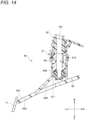
FIG. 14 illustrates a cross section along the line XIV-XIV inFIG. 13 and viewed from the arrowed direction. Thecleaning device 40 includes a joint 42. One end of a supply pipe (not illustrated) of the cleaning liquid W is connected to the joint 42. The joint 42 includes achannel 421 adapted to be communicated with the supply pipe. - On the other hand, the
nozzle 41 includes anoutlet 411 and achannel 412. Thechannel 412 communicates with theoutlet 411. As thenozzle 41 is connected to the joint 42, thechannel 412 and thechannel 421 communicate with each other. As a result, a channel for the cleaning liquid W extending from the supply pipe to theoutlet 411 is formed. The cleaning liquid W is jetted from theoutlet 411. - As illustrated in
FIGS. 12 and14 , thesupport 64 includes abracket portion 640. Thebracket portion 640 extends from aninner face 641 of thesupport 64 so as to have a hollowed cylindrical shape. - On the other hand, the
cleaning device 40 includes an engagingportion 44. The engagingportion 44 is configured to engage with thebracket portion 640 to hold thenozzle 41 in place relative to thebracket portion 640. The engagingportion 44 may be implemented by a well-known snap-fit structure or the like. - In other words, the
cleaning device 40 is attached to thesupport 64 from the side corresponding to theinner face 641. The position of thenozzle 41 in thecleaning device 40 is unchanged and is distinguished from a cleaning device with a so-called pop-up nozzle. - As illustrated in
FIGS. 13 and14 , thesupport 64 has a recessedface 644. The recessedface 644 is formed as a face continuous with theouter face 643 of thesupport 64 and recessed to the side corresponding to theinner face 641 relative to theouter face 643. On the other hand, the recessedface 644 communicates with an inner circumferential face of thebracket portion 640. - As the
cleaning device 40 is attached to thesupport 64, thenozzle 41 is disposed such that at least a portion thereof is covered by thesupport 64 when viewed from a side corresponding to theouter face 643 of thesupport 64. The arrangement of thenozzle 41 is determined so that the jetted cleaning liquid W can be guided to thetranslucent cover 71 of thelighting device 70 by the recessedface 644 of thesupport 64. - In the configuration according to the present embodiment, the
cleaning device 40 can be attached to thesupport 64 with a simple operation of engaging thenozzle 41 with thesupport 64 from the side corresponding to theinner face 641 of thesupport 64 with the use of the engagingportion 44. Since it is possible to eliminate the need for work from the side corresponding to theouter face 643 of thesupport 64, it is possible to simplify the production equipment and improve the productivity. - In addition, since it is possible to make it difficult to view the
nozzle 41 from the side corresponding to theouter face 643 of thesupport 64, the visibility of thecleaning device 40 can be reduced. - The arrangement of the
nozzle 41 may be determined so that the jetted cleaning liquid W is deflected toward thetranslucent cover 71 by a part of the recessedface 644. An arrow indicated with a chain line inFIG. 13 represents a path of the cleaning liquid W assumed when the cleaning liquid W is not subjected to the deflection by the recessedface 644. It is conceivable that the cleaning liquid W that is not deflected by the recessedface 644 is consumed without contributing to the cleaning of thetranslucent cover 71. By determining the arrangement of thenozzle 41 as described above, it is possible to improve the utilization efficiency of the cleaning liquid W. -
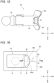
FIG. 15 illustrates an appearance of acleaning device 50 according to a fifth embodiment. As illustrated inFIG. 16 , thecleaning device 50 is a device adapted to be attached to asupport 65 to clean thelighting device 70. Thesupport 65 may be a component constituting a part of thevehicle 80 illustrated inFIG. 3 . - As illustrated in
FIG. 16 , thecleaning device 50 includes anozzle 51. Thecleaning device 50 is configured to perform cleaning by jetting cleaning liquid W from thenozzle 51 toward thetranslucent cover 71. -
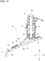
FIG. 17 illustrates a cross section along the line XVII-XVII inFIG. 16 and viewed from the arrowed direction. Thecleaning device 50 includes a joint 52. One end of a supply pipe (not illustrated) of the cleaning liquid W is connected to the joint 52. The joint 52 includes achannel 521 adapted to be communicated with the supply pipe. - On the other hand, the
nozzle 51 includes anoutlet 511 and achannel 512. Thechannel 512 communicates with theoutlet 511. As thenozzle 51 is connected to the joint 52, thechannel 512 and thechannel 521 communicate with each other. As a result, a channel for the cleaning liquid W extending from the supply pipe to theoutlet 511 is formed. The cleaning liquid W is jetted from theoutlet 511. - The
cleaning device 50 includes abracket 53. Thebracket 53 is configured to hold thenozzle 51 in place. In other words, the position of thenozzle 51 in thecleaning device 50 is unchanged, and is distinguished from a cleaning device with a so-called pop-up nozzle. - The
cleaning device 50 includes anadhesive portion 54. Theadhesive portion 54 adheres thebracket 53 to aninner face 651 of thesupport 65. In other words, thecleaning device 50 is attached to thesupport 65 from the side corresponding to theinner face 651. - In this example, the
adhesive portion 54 is implemented by a tape member having an adhesive layer on both faces thereof. One adhesive layer in the tape member is adhered to a supportedface 531 of thebracket 53. The other adhesive layer is adhered to theinner face 651 of thesupport 65. - It should be noted that the
adhesive portion 54 may be implemented by adhesive agent applied when thecleaning device 50 is attached to thesupport 65. - As illustrated in
FIG. 16 , thesupport 65 has anopening 652. Theopening 652 is formed so as to be adjacent to thetranslucent cover 71 of thelighting device 70. As thecleaning device 50 is attached to thesupport 65, thenozzle 51 is disposed so that the cleaning liquid W is jetted to thetranslucent cover 71 through theopening 652. In addition, thenozzle 51 is disposed so that at least a portion thereof is covered by thesupport 65 when viewed from a side corresponding to anouter face 653 of thesupport 65. - More specifically, the
opening 652 is formed such that aninner edge 652a faces thetranslucent cover 71. In other words, there is no object that blocks the cleaning liquid W between theinner edge 652a and thetranslucent cover 71. - In the configuration according to the present embodiment, the
bracket 53 and theinner face 651 are adhered by theadhesive portion 54 with a simple operation of pressing thebracket 53 against thesupport 65 from the side corresponding to theinner face 651 of thesupport 65, so that thecleaning device 50 can be attached to thesupport 65. Since the work from the side corresponding to theouter face 653 of thesupport 65 can be eliminated, it is possible to simplify the production equipment and improve the productivity. - In addition, since the
translucent cover 71 of thelighting device 70 and thenozzle 51 can be directly faced each other through theopening 652 of thesupport 65, the flexibility as for the locational relationship therebetween can be increased. - In addition, it is possible to make difficult to view the bracket 43 from the side corresponding to the
outer face 633 of thesupport 65. Coupled with the appearance that at least a portion of thenozzle 51 is covered by thesupport 65 itself when viewed from the side corresponding to theouter face 653 of thesupport 65, the visibility of thecleaning device 50 can be reduced. -
FIG. 18 illustrates an appearance of acleaning device 90 according to a sixth embodiment as viewed from the front side. As illustrated inFIG. 19 , thecleaning device 90 is a device adapted to be attached to asupport 69 to clean thelighting device 70. Thesupport 69 may be a component constituting a part of thevehicle 80 illustrated inFIG. 3 . - As illustrated in
FIG. 19 , thecleaning device 90 includes anozzle 91. Thecleaning device 90 is configured to perform cleaning by jetting cleaning liquid W from thenozzle 91 toward thetranslucent cover 71. -
FIG. 20 illustrates a cross section along the line XX-XX inFIG. 19 and viewed from the arrowed direction. Thecleaning device 90 includes a joint 92. One end of a supply pipe (not illustrated) of the cleaning liquid W is connected to the joint 92. The joint 92 includes a channel adapted to be communicated with the supply pipe. - On the other hand, the
nozzle 91 includes an outlet 911 and a channel. The channel communicates with the outlet 911. As thenozzle 91 is connected to the joint 92, the channels communicate with each other. As a result, a channel for the cleaning liquid W extending from the supply pipe to the outlet 911 is formed. The cleaning liquid W is jetted from the outlet 911. - The
cleaning device 90 includes abracket 93. Thebracket 93 is configured to hold thenozzle 91 in place. In other words, the position of thenozzle 91 in thecleaning device 90 is unchanged, and is distinguished from a cleaning device with a so-called pop-up nozzle. - As illustrated in
FIG. 18 , thecleaning device 90 includes anadhesive portion 94. As illustrated inFIG. 20 , theadhesive portion 94 adheres thebracket 93 to aninner face 691 of thesupport 69. In other words, thecleaning device 90 is attached to thesupport 69 from the side corresponding to theinner face 691. - In this example, the
adhesive portion 94 is implemented by a tape member having an adhesive layer on both faces thereof. One adhesive layer in the tape member is adhered to a supportedface 931 of thebracket 93. The other adhesive layer is adhered to theinner face 691 of thesupport 69. - It should be noted that the
adhesive portion 94 may be implemented by adhesive agent applied when thecleaning device 90 is attached to thesupport 69. - As illustrated in
FIG. 18 , thebracket 93 includes aguide 932 and acover 933. On the other hand, as illustrated inFIGS. 19 and20 , anopening 692 is formed in thesupport 69. As thecleaning device 90 is attached to thesupport 69, theguide 932 and thecover 933 are exposed on the side corresponding to anouter face 693 of thesupport 69 through theopening 692. - As illustrated in
FIGS. 18 and 19 , theguide 932 has a recessedface 932a. The recessedface 932a has a dimension and a shape capable of guiding the cleaning liquid W jetted from thenozzle 91 to thetranslucent cover 71. - The
cover 933 is formed so as to cover at least a portion of thenozzle 91 when viewed from a side corresponding to theouter face 693 of thesupport 69. - As illustrated in
FIGS. 19 and20 , anouter edge 932b of theguide 932 and anouter edge 933a of thecover 933 are located inside aninner edge 692a of theopening 692. Accordingly, thebracket 93 and theinner face 691 are adhered to by theadhesive portion 94 with a simple operation of causing theguide 932 and thecover 933 to pass through the opening 692 from the side corresponding to theinner face 691 of thesupport 69, so that thecleaning device 90 can be attached to thesupport 69. Since it is possible to eliminate the need for work from the side corresponding to theouter face 693 of thesupport 69, it is possible to simplify the production equipment and improve the productivity. - In addition, it is possible to reduce the dimension of a portion of the
bracket 93 exposed on the side corresponding to theouter face 693 of thesupport 69 through theopening 692. Coupled with the appearance that at least a portion of thenozzle 91 is covered by thecover 933 when viewed from the side corresponding to theouter face 693, the visibility of thecleaning device 90 can be reduced. - As illustrated in
FIGS. 18 and20 , thebracket 93 is formed withmultiple apertures 934. Eachaperture 934 is a through hole having a dimension that allows passage of the cleaning liquid W. Eachaperture 934 communicates a side of thebracket 93 facing an outer side of thesupport 69 and a side of thebracket 93 facing an inner side of thesupport 69. - Each
aperture 934 is disposed so as to be covered by thesupport 69 when thecleaning device 90 is attached to thesupport 69. Anaperture 934a, that is one of themultiple apertures 934, is disposed such that at least a portion thereof is located vertically under thenozzle 91. - A portion of the cleaning liquid W jetted toward the
translucent cover 71 of thelighting device 70 may descend along theouter face 693 of thesupport 69 and enter theopening 692. Such cleaning liquid as returned may include dust and mud peeled from thetranslucent cover 71 by the cleaning. Since theapertures 934 as described above are formed in thebracket 93, it is possible to promote drain of the cleaning liquid that has returned and entered theopening 692. As a result, it is possible to suppress occurrence of a situation that the jetting of the cleaning liquid W from thenozzle 91 is obstructed by dust and/or mud that have entered theopening 692 together with the returned cleaning liquid and fixed to theguide 932 while being dried. - In addition, since each
aperture 934 is disposed so as to be covered by thesupport 69, it is possible to reduce the visibility from the side corresponding to theouter face 693 of thesupport 69. Accordingly, it is possible to suppress the influence of the configuration for draining the cleaning liquid that has returned and entered theopening 692 on the appearance of thecleaning device 90. - In this example, four
apertures 934 are formed. However, the number of theapertures 934 can be appropriately determined as long as at least oneaperture 934 is located vertically under the nozzle 91 (in other words, at a location where the drain efficiency is the highest). - As illustrated in
FIGS. 18 and 19 , theguide 932 may include adeflector 932c. Thedeflector 932c is formed as a wall capable of deflecting the traveling direction of the cleaning liquid W jetted from thenozzle 91 toward thetranslucent cover 71. - An arrow indicated by a chain line in
FIG. 19 represents a path of the cleaning liquid W assumed when thedeflector 932c is not present. It is conceivable that the cleaning liquid W that is not deflected by thedeflector 932c is consumed without contributing to the cleaning of thetranslucent cover 71. By providing thedeflector 932c as in this example, it is possible to improve the utilization efficiency of the cleaning liquid W. -
FIG. 21 illustrates the appearance of thecleaning device 90 as viewed from the direction along the arrow XXI inFIG. 20 . Thedeflector 932c is formed withmultiple apertures 935. Eachaperture 935 faces the recessedface 932a of theguide 932. Eachaperture 935 is a through hole having a dimension that allows passage of the cleaning liquid W. Eachaperture 935 communicates a side of thebracket 93 facing an outer side of thesupport 69 and a side of thebracket 93 facing an inner side of thesupport 69. - According to such a configuration, it is possible to further promote the drain of the cleaning liquid that has returned and entered the
opening 692. In addition, since eachaperture 935 is formed at a position where is difficult to be visually recognized in the front view of thecleaning device 90, it is possible to suppress the configuration for draining the returned cleaning liquid on the appearance of thecleaning device 90. - In this example, two
apertures 935 are formed. However, the number of theapertures 935 may be appropriately determined. In a case where only oneaperture 935 is formed, it is preferable that the opening is disposed below thenozzle 91 at a position facing the recessedface 932a. In a case where theaperture 935 is formed, theaperture 934 described above may be omitted. - The above embodiments are merely illustrative to facilitate understanding of the presently disclosed subject matter. The configuration according to each of the above embodiments can be appropriately changed or combined with other embodiments without departing from the scope of the presently disclosed subject matter.
- For example, at least one of the
aperture 934 and theaperture 935 of thecleaning device 90 according to the sixth embodiment may be formed in each of thebracket 13 of thecleaning device 10 according to the first embodiment, thebracket 23 of thecleaning device 20 according to the second embodiment, and thebracket 33 of thecleaning device 30 according to the third embodiment. - The target to be cleaned by the cleaning device according to each embodiment is not limited to the
translucent cover 71 of thelighting device 70. Examples of other targets include a sensing face of a sensor that senses information around thevehicle 80 with light, or a surface of a member through which such light passes. - For cleaning the target, liquid such as water or gas such as air may be used. The liquid or gas is an example of the fluid.
- The cleaning device according to each embodiment may be installed in a mobility other than the vehicle. Examples of other mobilities include an aircraft, a flying object, a ship, and the like. The mobility may not require a driver.
- The cleaning device according to each embodiment does not have to be installed in a mobility. For example, the cleaning device according to each embodiment may be installed in a house, a facility, a transportation infrastructure, or the like and used for cleaning the target as exemplified above.
- The present application is based on
Japanese Patent Application No. 2022-086820 filed on May 27, 2022 Japanese Patent Application No. 2022-142167 filed on September 7, 2022
Claims (13)
- A cleaning device adapted to be attached to a support having an opening, the cleaning device comprising:a nozzle configured to jet fluid toward a target;a bracket holding the nozzle in place; andan adhesive portion adhering the bracket to an inner face of the support,wherein the bracket includes:a guide having a recessed face that is configured to guide the fluid toward the target; anda cover at least partially covering the nozzle as viewed from a side corresponding to an outer face of the support; andwherein an outer edge of the guide and an outer edge of the cover are configured to be located inside an inner edge of the opening when the cleaning device is attached to the support.
- A cleaning device adapted to be attached to a support having an opening, the cleaning device comprising:a nozzle configured to jet fluid toward a target;a bracket holding the nozzle in place; andan adhesive portion adhering the bracket to an inner face of the support,wherein the bracket includes a guide having a recessed face that is configured to guide the fluid toward the target;wherein the nozzle is disposed so as to be at least partially covered by the support when the cleaning device is attached to the support; andwherein an outer edge of the guide is configured to be located inside an inner edge of the opening when the cleaning device is attached to the support.
- The cleaning device according to claim 1 or 2, further comprising:
a deflector configured to deflect the fluid toward the target. - The cleaning device according to any one of claims 1 to 3,wherein the bracket is formed with an aperture that allows at least the fluid to pass through; andwherein the opening is disposed so as to be covered by the support at least at a position where is vertically under the nozzle when the cleaning device is attached to the support.
- The cleaning device according to any one of claims 1 to 4,wherein the bracket is formed with an aperture that allows at least the fluid to pass through; andwherein the opening is disposed so as to face the guide.
- A cleaning device adapted to be attached to a support having a recessed face, the cleaning device comprising:a nozzle configured to jet fluid toward a target;a bracket holding the nozzle in place; andan adhesive portion adhering the bracket to an inner face of the support,wherein the bracket includes an opening configured to receive the recessed face at a side corresponding to the inner face of the support;wherein the nozzle is disposed such that the fluid is guided toward the target by the recessed face when the cleaning device is attached to the support; andwherein the nozzle is disposed so as to be at least partially covered by the support as viewed from a side corresponding to an outer face of the support when the cleaning device is attached to the support.
- The cleaning device according to claim 6,wherein the bracket is formed with an aperture that allows at least the fluid to pass through; andwherein the opening is disposed so as to be covered by the support at least at a position where is vertically under the nozzle when the cleaning device is attached to the support.
- The device according to any one of claim 6 or 7,wherein the bracket is formed with an aperture that allows at least the fluid to pass through; andwherein the opening is disposed so as to face the guide.
- A cleaning device adapted to be attached to a support having a recessed face, the cleaning device comprising:a nozzle configured to jet fluid toward a target; andan engaging portion configured to engage with the support at a side corresponding to an inner face of the support to hold the nozzle in place,wherein the nozzle is disposed such that the fluid is guided toward the target by the recessed face when the cleaning device is attached to the support; andwherein the nozzle is disposed so as to be at least partially covered by the support as viewed from a side corresponding to an outer face of the support when the cleaning device is attached to the support.
- The cleaning device according to claim 9,
wherein the nozzle is disposed such that the fluid is deflected toward the target by a part of the recessed face when the cleaning device is attached to the support. - A cleaning device adapted to be attached to a support having an opening, the cleaning device comprising:a nozzle configured to jet fluid toward a target;a bracket holding the nozzle in place; andan adhesive portion adhering the bracket to an inner face of the support,wherein the nozzle is disposed such that the fluid that has passed the opening is jetted toward the target when the cleaning device is attached to the support; andwherein the nozzle is disposed so as to be at least partially covered by the support as viewed from a side corresponding to an outer face of the support when the cleaning device is attached to the support.
- The cleaning device according to any one of claims 1 to 11,
wherein the support is a part of a mobility. - The cleaning device according to any one of claims 1 to 11,
wherein the target is a part of a lighting device.
Applications Claiming Priority (3)
| Application Number | Priority Date | Filing Date | Title |
|---|---|---|---|
| JP2022086820 | 2022-05-27 | ||
| JP2022142167 | 2022-09-07 | ||
| PCT/JP2023/019711 WO2023229028A1 (en) | 2022-05-27 | 2023-05-26 | Cleaning device |
Publications (1)
| Publication Number | Publication Date |
|---|---|
| EP4534366A1 true EP4534366A1 (en) | 2025-04-09 |
Family
ID=88919490
Family Applications (1)
| Application Number | Title | Priority Date | Filing Date |
|---|---|---|---|
| EP23811900.2A Pending EP4534366A1 (en) | 2022-05-27 | 2023-05-26 | Cleaning device |
Country Status (4)
| Country | Link |
|---|---|
| EP (1) | EP4534366A1 (en) |
| JP (1) | JPWO2023229028A1 (en) |
| CN (1) | CN119278150A (en) |
| WO (1) | WO2023229028A1 (en) |
Family Cites Families (11)
| Publication number | Priority date | Publication date | Assignee | Title |
|---|---|---|---|---|
| JPS598923Y2 (en) * | 1978-04-14 | 1984-03-21 | トヨタ自動車株式会社 | Window wash nozzle cover structure |
| JPH0342356A (en) * | 1989-07-07 | 1991-02-22 | Nissan Motor Co Ltd | Mounting structure for window washer nozzle |
| JP2510270Y2 (en) * | 1989-12-05 | 1996-09-11 | 自動車電機工業株式会社 | Washer nozzle mounting structure |
| JPH0717367A (en) * | 1993-06-30 | 1995-01-20 | Suzuki Motor Corp | Washer device for vehicle headlamp |
| DE19501210A1 (en) * | 1995-01-17 | 1996-07-18 | Teves Gmbh Alfred | Module for a motor vehicle |
| JP2010195360A (en) * | 2009-02-27 | 2010-09-09 | Daikyonishikawa Corp | Vehicular washer nozzle |
| JP6096032B2 (en) * | 2013-03-28 | 2017-03-15 | 株式会社小糸製作所 | Vehicle cleaning device |
| JP6871529B2 (en) * | 2017-03-02 | 2021-05-12 | 三菱自動車工業株式会社 | Arrangement structure of washer nozzle |
| JP7121508B2 (en) | 2018-03-14 | 2022-08-18 | 株式会社小糸製作所 | vehicle cleaner |
| JP2022086820A (en) | 2020-11-30 | 2022-06-09 | 株式会社アイシン | Stator |
| JP7588011B2 (en) | 2021-03-16 | 2024-11-21 | 日産自動車株式会社 | Vehicle abnormality notification device and vehicle abnormality notification method |
-
2023
- 2023-05-26 WO PCT/JP2023/019711 patent/WO2023229028A1/en not_active Ceased
- 2023-05-26 CN CN202380043018.7A patent/CN119278150A/en active Pending
- 2023-05-26 EP EP23811900.2A patent/EP4534366A1/en active Pending
- 2023-05-26 JP JP2024523361A patent/JPWO2023229028A1/ja active Pending
Also Published As
| Publication number | Publication date |
|---|---|
| CN119278150A (en) | 2025-01-07 |
| JPWO2023229028A1 (en) | 2023-11-30 |
| WO2023229028A1 (en) | 2023-11-30 |
Similar Documents
| Publication | Publication Date | Title |
|---|---|---|
| US9644583B2 (en) | Fuel pipe protective structure | |
| US12391218B2 (en) | System for cleaning a sensor/transmitter of a motor vehicle | |
| CN102084563A (en) | Grommet | |
| WO2009147760A1 (en) | Grommet | |
| CN102084564A (en) | Guard ring | |
| WO2009147763A1 (en) | Grommet | |
| EP2108569B1 (en) | Rear panel arrangement for a motor vehicle | |
| EP0206684A2 (en) | Defroster structure for vehicle | |
| JPWO2013080965A1 (en) | Design parts arrangement structure for vehicles | |
| JP5136222B2 (en) | Grommet | |
| US20190176691A1 (en) | Open roof construction for a vehicle | |
| EP3705328B1 (en) | Door sash structure | |
| US20170203638A1 (en) | Sash coupling structure and method for sash coupling | |
| EP3705325B1 (en) | Channel and door sash structure | |
| US9499211B2 (en) | Ventilation crossmember for a motor vehicle | |
| CN119278150A (en) | Cleaning device | |
| US20240157392A1 (en) | Nozzle for Applying an Adhesive Material, Application Device for Applying an Adhesive Material, Method for Applying an Adhesive Material, and Component for a Vehicle | |
| US20240385412A1 (en) | Mirror device for a head-up display with specific air bubble reduction in the mirror region, as well as a head-up display and motor vehicle | |
| JP5388292B2 (en) | Reservoir tank connection connector, master cylinder including the same, and brake device using the master cylinder | |
| JP7329176B2 (en) | faucet device | |
| CN110426693B (en) | LiDAR and Vehicles Equipped with It | |
| JP2020050171A (en) | Waterproof structure of vehicle door | |
| JPWO2018079483A1 (en) | Fastener | |
| JP4420403B2 (en) | Cowl structure | |
| KR102751222B1 (en) | Pressure and temperature sensor fastening structure for sensor cleaning system |
Legal Events
| Date | Code | Title | Description |
|---|---|---|---|
| STAA | Information on the status of an ep patent application or granted ep patent |
Free format text: STATUS: THE INTERNATIONAL PUBLICATION HAS BEEN MADE |
|
| PUAI | Public reference made under article 153(3) epc to a published international application that has entered the european phase |
Free format text: ORIGINAL CODE: 0009012 |
|
| STAA | Information on the status of an ep patent application or granted ep patent |
Free format text: STATUS: REQUEST FOR EXAMINATION WAS MADE |
|
| 17P | Request for examination filed |
Effective date: 20241127 |
|
| AK | Designated contracting states |
Kind code of ref document: A1 Designated state(s): AL AT BE BG CH CY CZ DE DK EE ES FI FR GB GR HR HU IE IS IT LI LT LU LV MC ME MK MT NL NO PL PT RO RS SE SI SK SM TR |
|
| DAV | Request for validation of the european patent (deleted) | ||
| DAX | Request for extension of the european patent (deleted) |