EP4534240A2 - Schalensystem zur robotischen teilverarbeitung - Google Patents
Schalensystem zur robotischen teilverarbeitung Download PDFInfo
- Publication number
- EP4534240A2 EP4534240A2 EP24177948.7A EP24177948A EP4534240A2 EP 4534240 A2 EP4534240 A2 EP 4534240A2 EP 24177948 A EP24177948 A EP 24177948A EP 4534240 A2 EP4534240 A2 EP 4534240A2
- Authority
- EP
- European Patent Office
- Prior art keywords
- tray
- support
- trays
- robot
- base
- Prior art date
- Legal status (The legal status is an assumption and is not a legal conclusion. Google has not performed a legal analysis and makes no representation as to the accuracy of the status listed.)
- Pending
Links
Images


Classifications
-
- B—PERFORMING OPERATIONS; TRANSPORTING
- B25—HAND TOOLS; PORTABLE POWER-DRIVEN TOOLS; MANIPULATORS
- B25J—MANIPULATORS; CHAMBERS PROVIDED WITH MANIPULATION DEVICES
- B25J19/00—Accessories fitted to manipulators, e.g. for monitoring, for viewing; Safety devices combined with or specially adapted for use in connection with manipulators
- B25J19/007—Means or methods for designing or fabricating manipulators
-
- B—PERFORMING OPERATIONS; TRANSPORTING
- B23—MACHINE TOOLS; METAL-WORKING NOT OTHERWISE PROVIDED FOR
- B23Q—DETAILS, COMPONENTS, OR ACCESSORIES FOR MACHINE TOOLS, e.g. ARRANGEMENTS FOR COPYING OR CONTROLLING; MACHINE TOOLS IN GENERAL CHARACTERISED BY THE CONSTRUCTION OF PARTICULAR DETAILS OR COMPONENTS; COMBINATIONS OR ASSOCIATIONS OF METAL-WORKING MACHINES, NOT DIRECTED TO A PARTICULAR RESULT
- B23Q7/00—Arrangements for handling work specially combined with or arranged in, or specially adapted for use in connection with, machine tools, e.g. for conveying, loading, positioning, discharging, sorting
- B23Q7/04—Arrangements for handling work specially combined with or arranged in, or specially adapted for use in connection with, machine tools, e.g. for conveying, loading, positioning, discharging, sorting by means of grippers
-
- B—PERFORMING OPERATIONS; TRANSPORTING
- B25—HAND TOOLS; PORTABLE POWER-DRIVEN TOOLS; MANIPULATORS
- B25J—MANIPULATORS; CHAMBERS PROVIDED WITH MANIPULATION DEVICES
- B25J9/00—Programme-controlled manipulators
- B25J9/16—Programme controls
- B25J9/1656—Programme controls characterised by programming, planning systems for manipulators
- B25J9/1661—Programme controls characterised by programming, planning systems for manipulators characterised by task planning, object-oriented languages
-
- B—PERFORMING OPERATIONS; TRANSPORTING
- B25—HAND TOOLS; PORTABLE POWER-DRIVEN TOOLS; MANIPULATORS
- B25J—MANIPULATORS; CHAMBERS PROVIDED WITH MANIPULATION DEVICES
- B25J5/00—Manipulators mounted on wheels or on carriages
- B25J5/007—Manipulators mounted on wheels or on carriages mounted on wheels
-
- B—PERFORMING OPERATIONS; TRANSPORTING
- B25—HAND TOOLS; PORTABLE POWER-DRIVEN TOOLS; MANIPULATORS
- B25J—MANIPULATORS; CHAMBERS PROVIDED WITH MANIPULATION DEVICES
- B25J9/00—Programme-controlled manipulators
- B25J9/0093—Programme-controlled manipulators co-operating with conveyor means
-
- B—PERFORMING OPERATIONS; TRANSPORTING
- B25—HAND TOOLS; PORTABLE POWER-DRIVEN TOOLS; MANIPULATORS
- B25J—MANIPULATORS; CHAMBERS PROVIDED WITH MANIPULATION DEVICES
- B25J9/00—Programme-controlled manipulators
- B25J9/0096—Programme-controlled manipulators co-operating with a working support, e.g. work-table
-
- B—PERFORMING OPERATIONS; TRANSPORTING
- B25—HAND TOOLS; PORTABLE POWER-DRIVEN TOOLS; MANIPULATORS
- B25J—MANIPULATORS; CHAMBERS PROVIDED WITH MANIPULATION DEVICES
- B25J9/00—Programme-controlled manipulators
- B25J9/16—Programme controls
- B25J9/1615—Programme controls characterised by special kind of manipulator, e.g. planar, scara, gantry, cantilever, space, closed chain, passive/active joints and tendon driven manipulators
- B25J9/162—Mobile manipulator, movable base with manipulator arm mounted on it
-
- B—PERFORMING OPERATIONS; TRANSPORTING
- B25—HAND TOOLS; PORTABLE POWER-DRIVEN TOOLS; MANIPULATORS
- B25J—MANIPULATORS; CHAMBERS PROVIDED WITH MANIPULATION DEVICES
- B25J9/00—Programme-controlled manipulators
- B25J9/16—Programme controls
- B25J9/1628—Programme controls characterised by the control loop
- B25J9/1653—Programme controls characterised by the control loop parameters identification, estimation, stiffness, accuracy, error analysis
-
- B—PERFORMING OPERATIONS; TRANSPORTING
- B65—CONVEYING; PACKING; STORING; HANDLING THIN OR FILAMENTARY MATERIAL
- B65D—CONTAINERS FOR STORAGE OR TRANSPORT OF ARTICLES OR MATERIALS, e.g. BAGS, BARRELS, BOTTLES, BOXES, CANS, CARTONS, CRATES, DRUMS, JARS, TANKS, HOPPERS, FORWARDING CONTAINERS; ACCESSORIES, CLOSURES, OR FITTINGS THEREFOR; PACKAGING ELEMENTS; PACKAGES
- B65D21/00—Nestable, stackable or joinable containers; Containers of variable capacity
- B65D21/02—Containers specially shaped, or provided with fittings or attachments, to facilitate nesting, stacking, or joining together
- B65D21/0209—Containers specially shaped, or provided with fittings or attachments, to facilitate nesting, stacking, or joining together stackable or joined together one-upon-the-other in the upright or upside-down position
- B65D21/0215—Containers with stacking feet or corner elements
Definitions
- each alignment feature is connected to the lower surface of the base and each of the at least one stacking posts is connected to the upper surface of the base of each of the plurality of trays; and wherein the trays are configured to be stacked in alignment with one another by placing the alignment features of an upper tray onto the centering tips of the at least one stacking post connected to a lower tray.
- the present disclosure provides a tray for use in robotic part processing, comprising: a base including an upper surface and a lower surface; a frame connected to the upper surface and including a plurality of segments defining a plurality of pockets; a plurality of alignment features on one of the upper surface or the lower surface of the base; and a plurality of spacers integrally formed on another of the upper surface or the lower surface of the base, each spacer being configured to engage with an alignment feature on one of an upper surface or a lower surface of a base of a different tray.
- the tray further comprises a pad attached to the upper surface of the base.
- each of the alignment ends of the stackable posts includes an interior surface shaped to receive a centering end of another stackable post.
- each of the plurality of bolts includes a head, the bolt being configured to extend through an alignment feature and the base of a tray, and to be threaded into a central threaded opening of a stackable post, thereby causing the head of the bolt to seat within a recess of the alignment feature and connecting the alignment feature and the stackable post to the base.
- the central threaded opening extends from the centering end of the stackable post to the alignment end of the stackable post.
- supports 20 may be moved from docking station 18 to docking station 18 to be used in conjunction with any of the plurality of processing machines 12.
- the docking station 18 is portable and can be moved to and fixed in position adjacent any of the plurality of processing machines 12 to enable use of the tray system 10 to perform different processing operations.
- the mating component and docking member 40 can take any of a variety of different forms, such as mechanical connectors, electro-mechanical connectors, spring-loaded ball and detent components, magnetic components, and/or simply a protrusion and recess connection between the mating component and the docking member 40.
- the docking member 40 is positioned within the dock 24A-C in a precise location by the mating component to orient the support 20A-C and the contents of the support 20A-C for part processing as is further described below. It should be understood that while three docks 24A-C are shown on the example docking station 18, more or fewer docks may be used.
- the supports 20A-C are substantially identical and interchangeable. Accordingly, only one support 20A is described in detail herein.
- the support 20A generally includes a base 28 having an upper surface 30, a lower surface 32, a forward edge 34, a rearward edge 36, a plurality of wheels 38 connected to the lower surface 32 of the base 28, a docking member 40 connected to the lower surface 32 of the base 28 adjacent the forward edge 34, alignment members 42 mounted to the upper surface of the base 28, and a handle 44 for moving the support 20A from location to location.
- the alignment members 42 are configured to precisely position a tray on the support 20A as is further described below. In the embodiment shown, four alignment members 42 are used, one adjacent each corner of the base 28 of the support 20A.
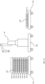
- a support 20 is shown with a plurality of trays 56 stacked onto the support 20. It should be understood that while only three trays 56 are shown in FIG. 5 , more or fewer trays 56 may be stacked onto a support 20 according to the principles of the present disclosure.
- the support 20 includes the plurality of alignment members 42 on its upper surface 30.
- the alignment features 84 on the lower surface 72 of the first tray 56A align with the alignment members 42 on the support 20 to precisely position the first tray 56A on the support 20.
- the support 20 may include the alignment features 84 and the lower surface 72 of the trays 56 may include the alignment members 42.
- the extension 143 is shown extending through the openings 135 through the base 58 and the frame 62.
- the head 131 of the bolt 127 may seat within a recess 137 formed in the alignment feature 84 as the threaded shaft 129 is threaded into the threaded opening 124 of the post 104. In this manner, the alignment feature 84 and the post 104 may be simultaneously attached to the tray 56.
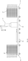
- the robot 46 After transferring an empty tray (e.g., tray A1) from the support 20A to the outfeed support 20C (assuming the outfeed support 20C initially carries no trays), the robot 46 would then enter the lathe, remove the finished part from the sub-spindle and place it in the empty tray A1 on the outfeed support 20C. This process would continue until the tray A1 is full of finished parts. Then the robot 46 would remove another empty tray A2 from the support 20A and stack it onto tray A1 on outfeed cart 20C and continue the process.
- an empty tray e.g., tray A1
- the robot 46 After transferring an empty tray (e.g., tray A1) from the support 20A to the outfeed support 20C (assuming the outfeed support 20C initially carries no trays), the robot 46 would then enter the lathe, remove the finished part from the sub-spindle and place it in the empty tray A1 on the outfeed support 20C. This process would continue until the tray A1 is full of finished parts. Then the robot 46
- the robot 46 lifts the empty tray A1 and stacks it on top of the tray C 1 on the outfeed support 20C as shown in FIG. 12 .
- the manner of lifting and moving empty trays such as tray A1 is described in further detail herein.
- the robot 46 then begins removing workpieces 109 from the tray A2 of the infeed support 20A, placing them into the processing machine 12 for processing, removing them from the processing machine once processed, and loading the processed workpieces 109' into the tray A1.
- all of the workpieces 109 are removed from the tray A2, processed, and loaded as processed workpieces 109' into the tray A1 stacked on the tray C1 on the outfeed support 20C. This is shown in FIG. 13 .
- the side edges 157, 159 are substantially parallel to one another and substantially perpendicular to the outer edge 160 of the side plate 148.
- the inner edge 162 of the side plate 148 is integral with the inner edge 163 of the connecting plate 150.
- the outer edge 161 of the connecting plate 150 is curved to substantially match an outer dimension of a robot wrist 53 as is described below.
- a plurality of apertures 164 extend through the connecting plate 150 for attachment of the connecting plate 150 (and therefore the wrist attachment 146) to the robot wrist 53.
- the first segment 172 of the upper wall 170 of the interlock hook 166 extends away from the first segment 178 of the vertical wall 176 toward the first side edge 156 of the side plate 148 in substantially parallel relationship to the outer surface 152 of the side plate 148 and the second segment 174 of the upper wall 170 extends away from the second segment 180 of the vertical wall 176 toward the inner edge 162 of the side plate 148 in substantially parallel relationship to the outer surface 152 of the side plate 148.
- the vertical wall 176 supports the upper wall 170 at a spaced apart distance from the outer surface 152 of the side plate 148 to provide for engagement with the hook 96 attached to the frame 62 of the tray 56 as described below for lifting and moving the tray 56.
- any type of gripper 52 may be used on the robot 46 without regard for its ability to transport trays 56.
- the upper wall 170 of the interlock hook 166 is moved under the upper wall 128 of the hook 96 and the engagement pad 168 is moved into engagement with the length segment 90 of the frame 62.
- the robot arm 50 is then moved upwardly and because the hook 96 is offset from the center line 98 of the tray 56, torque is generated about the center line 98 by the weight of the tray 56 as indicated by arrow 194 (see also, FIG. 3 ). In this manner, the weight of the tray 56 balances against the engagement pad 168 to ensure that the tray 56 remains balanced and secure as the robot 46 moves the tray 56 from one support 20 to another support 20.
- FIGS. 22A-C One example alternative for engaging and moving a tray 56 is the engagement mechanism 398 depicted in FIGS. 22A-C .
- an engagement block 400 is attached to the underside of the base 58 of the tray 56 adjacent the side edge 76 at location that is offset from the end edge 78 of the base 58.
- the engagement block 400 includes a first outer surface 402, a second outer surface 404, a lower surface 406, an upper surface 408 and an inner surface 410.
- the first outer surface 402 is substantially perpendicular to the second outer surface 404, the lower surface 406 and the upper surface 408.
- a bore 412 is formed into the first outer surface 402 and includes an opening 414.
- the engagement mechanism 398 also includes mating block 424 as shown in FIG. 22B which is attached to the robot 46.
- the mating block 424 includes a first outer surface 426, a second outer surface 428, a lower surface (not shown), an upper surface 430, a first end surface 432, a second end surface 434, a first inner surface 436 and a second inner surface 438.
- the mating block 424 includes a first portion 440 and a second portion 442.
- a fixed pin 444 extends from the first inner surface 436 of the first portion 440 of the mating block 424.
- the fixed pin 444 includes a shaft 446 and a tapered end 448.
- the fixed pin 444 extends perpendicularly from the first inner surface 436 and has a longitudinal central axis 450.
- the longitudinal central axis 450 is spaced apart from the intersection between the first inner surface 436 and the second inner surface 438 by a distance that is equal to the distance between the longitudinal axis 420 of the bore 412 of the engagement block 400 and the intersection between the first outer surface 402 and the second outer surface 404 of the engagement block 400.
- the robot 42 moves the second inner surface 436 of the mating block 424 into engagement with the second outer surface 404 of the engagement block 400, the fixed pin 444 is aligned with the bore 412.
- the mating block 424 also includes a latch assembly 452 disposed on the second portion 442 of the mating block 424.
- the latch assembly 452 includes a movable pin 454 including a shaft 456 and a tapered end 458, a rod 460 connected to the shaft 456, and a biasing member 462.
- the latch assembly 452 is positioned in a bore 464 formed into the second inner surface 438 of the second portion 442 of the mating block 424. More specifically, the bore 464 includes an opening 466 in the second inner surface 438, a side wall 468, a shoulder 470 and an rod opening 472.
- the biasing member 462 in this embodiment is a coil spring.
- the rod 460 extends through the central portion of the biasing member 462.
- the rod 460 is retractable by an actuator (not shown) along its longitudinal axis to move the movable pin 454 to a retracted position wherein the pin 454 is substantially entirely disposed within the bore 464, thereby compressing the biasing member 462.
- the actuator may be mechanical, pneumatic, electrical or magnetic.
- the mating block 424 is thus fixed to the engagement block 400 by the fixed pin 444 and the movable pin 454.
- the robot 42 then moves the tray 56 to desired location, activates the actuator to move the movable pin 454 into the retracted position, and moves the mating block 424 to withdraw the fixed pin 444 from the bore 412, thereby disengaging the mating block 424 from the engagement block 400.
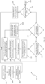
- the robot 46 begins moving workpieces from the infeed support 20 to the workspace 16, and moving processed workpieces from the workspace 16 to the outfeed support 20. Specifically, at step 208 the robot 46 is controlled to remove a workpiece from an uppermost tray 56 of a stack of trays 56 stacked on the infeed support 20. An example of this is depicted in FIG. 8 .
- the removed workpiece is placed by the robot 46 into the workspace 16 for processing by the processing machine 12. After the workpiece is processed, the robot 46 removes the processed workpiece at step 212 from the workspace 16.
- the robot 46 is controlled to place the processed workpiece into an uppermost tray 56 on the outfeed support 20 (e.g., empty tray C1 shown in FIG. 10 ).
- step 216 the controller 14 determines whether the uppermost tray 56 of the stack of trays 56 on the infeed support 20 is empty. If not, then the process returns to step 208 and repeats steps 210, 212 and 214. If the uppermost tray 56 of the stack of trays 56 on the infeed support 20 is empty (as depicted in the example of FIG. 11 ), then the controller 14 determines at step 220 whether the uppermost tray 56 is the bottom tray 56 on the infeed support 20 (i.e., the tray 56 stacked directly onto the support 20). If the tray 56 is not the bottom tray 56, then the controller 14 controls the robot 46 at step 218 to move the empty tray 56 from the infeed support 20 onto the uppermost tray 56 on the outfeed support 20.
- the trays 56 need not be stacked onto moveable objects such as supports 20. Instead, stacks of trays 56 may be presented to the robot 46 on a pallet or other supporting surface and empty trays 56 may be stacked onto another pallet or other supporting surface. Also, as should be apparent from the foregoing, the spacing and size of the pockets 92 of the frame 62 of a tray 56 containing workpieces 109 at the top of a stack of trays 56 on an infeed support 20 should be capable of accommodating the size of processed workpieces 109' from the next lower tray 56 in the stack. In other embodiments, an additional support 20 may be provided with a stack of empty trays 56 that matches the trays 56 on the infeed support 20. Those empty trays 20 may be loaded onto the outfeed support 20. In this embodiment, an additional support 20 would be needed to receive the empty trays 56 from the infeed support 20 since they will not be used to receive processed workpieces 109'.
- the controller 14 of the processing machine 12 or a separate controller knows, through user input or by means of detection and learning, the locations of the infeed support(s) 20 and the outfeed support 20, the spacing of the pockets 92 in each tray 56 on the supports 20, the dimensions of the workpieces 109 in each tray 56, and the vertical distance or height between adjacent stacked trays 56. This information may be saved and recalled for subsequent processing. Alternatively, the data may be stored on the supports 20 and transmitted to the controller 14 using RFID, QR code or other similar technology.
- the interface 500 also permits the user to specify the infeed and outfeed stock material dimensions, and all other necessary auxiliary parameters for the robot 42 and the processing machine 12 to handle and process the workpieces 109 (e.g., part weight, work holding parameters, part cleaning parameters, etc.).
- the user may also specify how many and where the unprocessed workpieces 109 are placed in the tray 56. It should be understood that each tray 56 may contain one or more types of workpieces 109 that can be queued for processing. Even though part stacking is generally not necessary (a benefit of the system described herein) it is still possible and may occasionally be useful for situations where the production run only requires one tray and the system operates essentially like a table feeding system.
- the user may enable part stacking by activating icon 510.
- the infeed trays 56 and their associated jobs are defined using the job manager software upfront before running the system
- the definitions of the infeed trays 56, their associated jobs and even the number of trays 56 to process can be defined remotely, outside of the job manager software, on a network, or be encoded or linked to in an RFID or QR code on the trays 56.
- the system may search for and detect the RFID or QR code of upper most available tray 56 in the infeed stack and begin processing the job(s) in that tray 56. The system would then repeat until no further unprocessed trays 56 are detected in the infeed stack.
- the feature also allows for the possibility to use autonomous vehicles for the infeed and outfeed supports 20 for continual autonomous production of parts. The system would then simply wait until the infeed support 20 and the outfeed support 20 are present to begin processing jobs.
- a solid spacer 602 can be placed between the base 58 and the frame 62 in a cut out portion of the pad 60.
- the bolt 127 is then passed through the spacer 600 and threaded into the threaded opening 124 of the stacking post 104.
- the force will not compress the pad 60 because the solid spacer 600 is in place.
- the auto calibration cycle will rely on the fact that there is a fixed height 600 for all the stacked parts and fixed dimension of the trays 56 that will allow the system to establish a coordinate system and fixed points across the tray 56 to map and interpolate the robot positions to the calibrated 3D space.
- the spacing of the pockets 92 in the tray 56 can be programmed in the job manager software and will not affect the calibration cycle.
- a first tray 56 can be stacked on the alignment members 42 of the support 20 and the spacers 100' of the tray 56 can be similarly measured and stored.
- a next tray 56 can then be stacked and automatically measured. This process continues until the full stack of trays 56 have been measured.
- the trays 56 should ideally be of the same spacing to map the full 3D array of trays 56. If the stack spacing between trays is changed for shorter or taller parts, the system will simply interpolate the tray location accordingly. Thus, the system can compute the locations for any tray 56 within the mapped 3D volume. Note that both the infeed support 20 and the outfeed support 20 would need to be calibrated using this method to map their respective 3D volumes accordingly.
Landscapes
- Engineering & Computer Science (AREA)
- Mechanical Engineering (AREA)
- Robotics (AREA)
- Health & Medical Sciences (AREA)
- General Health & Medical Sciences (AREA)
- Orthopedic Medicine & Surgery (AREA)
- Automatic Assembly (AREA)
- Stackable Containers (AREA)
Applications Claiming Priority (1)
| Application Number | Priority Date | Filing Date | Title |
|---|---|---|---|
| US18/202,570 US20240391100A1 (en) | 2023-05-26 | 2023-05-26 | Tray system for robotic part processing |
Publications (2)
| Publication Number | Publication Date |
|---|---|
| EP4534240A2 true EP4534240A2 (de) | 2025-04-09 |
| EP4534240A3 EP4534240A3 (de) | 2025-06-11 |
Family
ID=91247380
Family Applications (1)
| Application Number | Title | Priority Date | Filing Date |
|---|---|---|---|
| EP24177948.7A Pending EP4534240A3 (de) | 2023-05-26 | 2024-05-24 | Schalensystem zur robotischen teilverarbeitung |
Country Status (4)
| Country | Link |
|---|---|
| US (1) | US20240391100A1 (de) |
| EP (1) | EP4534240A3 (de) |
| CN (1) | CN119017433A (de) |
| TW (1) | TW202513416A (de) |
Families Citing this family (1)
| Publication number | Priority date | Publication date | Assignee | Title |
|---|---|---|---|---|
| JP7468503B2 (ja) * | 2021-12-28 | 2024-04-16 | トヨタ自動車株式会社 | 搬送ロボット |
Family Cites Families (10)
| Publication number | Priority date | Publication date | Assignee | Title |
|---|---|---|---|---|
| SE169180C1 (de) * | 1955-03-18 | 1959-10-27 | ||
| US3783800A (en) * | 1971-11-23 | 1974-01-08 | Keller & Co Masch C | Drying trolleys for bricks and other articles |
| DE3628516A1 (de) * | 1986-08-22 | 1988-03-03 | Fraunhofer Ges Forschung | Stapelbares flachmagazin |
| GB2260076A (en) * | 1991-10-01 | 1993-04-07 | Miles Roland William Bozeat | Dismantling and assembly apparatus and method |
| EE05754B1 (et) * | 2013-02-15 | 2015-08-17 | Out Of Box Oü | Distantsliitmiksüsteem vertikaalsete moodulsüsteemide koostamiseks ja selle süsteemi kasutamine |
| DE202017000563U1 (de) * | 2017-02-02 | 2017-03-13 | Hans Joseph Kölbl | Liquid Ständer (Liquid Rack) zur Aufnahme von Aroma-Flaschen |
| KR20190046212A (ko) * | 2017-10-25 | 2019-05-07 | 씨제이대한통운 (주) | 적치 로봇을 이용한 물류 이송 시스템 |
| DE102019113464A1 (de) * | 2019-05-21 | 2020-11-26 | Homag Gmbh | Mobile Führungsmaschine, Zelle und Verfahren zum Handhaben und/oder Bearbeiten von Werkstücken |
| FR3104053B1 (fr) * | 2019-12-09 | 2023-06-16 | Mecad Savoie Ind | Dispositif de robot universel de chargement et déchargement de tours à commande numérique |
| DE102021209011A1 (de) * | 2021-08-17 | 2023-02-23 | Festo Se & Co. Kg | Produktionseinrichtung |
-
2023
- 2023-05-26 US US18/202,570 patent/US20240391100A1/en active Pending
-
2024
- 2024-05-24 EP EP24177948.7A patent/EP4534240A3/de active Pending
- 2024-05-24 TW TW113119376A patent/TW202513416A/zh unknown
- 2024-05-27 CN CN202410663388.7A patent/CN119017433A/zh active Pending
Also Published As
| Publication number | Publication date |
|---|---|
| US20240391100A1 (en) | 2024-11-28 |
| CN119017433A (zh) | 2024-11-26 |
| EP4534240A3 (de) | 2025-06-11 |
| TW202513416A (zh) | 2025-04-01 |
Similar Documents
| Publication | Publication Date | Title |
|---|---|---|
| US8777552B2 (en) | System and methods for forming stacks | |
| CN107720292B (zh) | 一种上下料系统和上下料方法 | |
| US11826788B2 (en) | Item sorting system and method of sorting | |
| EP1391275A2 (de) | Vorrichtung zur Handhabung von Werkstücken | |
| EP4534240A2 (de) | Schalensystem zur robotischen teilverarbeitung | |
| WO2021087312A1 (en) | Mobile automated guided vehicle pallet stacker and destacker system and method therefor | |
| US6746203B2 (en) | Gripping and transport clamp mounted at the end of a robotic arm and method for operating the same | |
| US20180071808A1 (en) | A stacking line system, and a method for stacking blanks which are outputted from a blanking shear or press | |
| KR101875554B1 (ko) | 팔레트 공급 장치 및 이를 이용한 물류 자동화 시스템 | |
| TW202332554A (zh) | 多模式機器人末端執行器 | |
| KR102758845B1 (ko) | 로봇 키팅 기계 | |
| US20230107488A1 (en) | Stack containment structure | |
| HK40119105A (zh) | 用於机器人零件加工的托盘系统 | |
| CN119768256A (zh) | 用于机器人零件搬运的可配置容量的网格托盘 | |
| CN215660313U (zh) | 一种具备自检功能的抓取装置 | |
| CN114714130A (zh) | 一种模具镶块机械手转运结构及机械手转运系统 | |
| CN119730808A (zh) | 用于医学设备的操作工具 | |
| CA2357271C (en) | Gripping and transport clamp mounted at the end of a robotic arm and method for operating the same | |
| CN212146196U (zh) | 一种自动引导车装配工装 | |
| US12552047B2 (en) | Handling tool for medical equipment | |
| US20240067455A1 (en) | Part registration system and methods | |
| US20250100140A1 (en) | Autonomous end effector selection and mounting | |
| JPH0545492B2 (de) | ||
| JP7648838B1 (ja) | 搬送システムおよびロボット | |
| US20240351221A1 (en) | Robotic arm manipulator interchange tool |
Legal Events
| Date | Code | Title | Description |
|---|---|---|---|
| PUAI | Public reference made under article 153(3) epc to a published international application that has entered the european phase |
Free format text: ORIGINAL CODE: 0009012 |
|
| STAA | Information on the status of an ep patent application or granted ep patent |
Free format text: STATUS: THE APPLICATION HAS BEEN PUBLISHED |
|
| AK | Designated contracting states |
Kind code of ref document: A2 Designated state(s): AL AT BE BG CH CY CZ DE DK EE ES FI FR GB GR HR HU IE IS IT LI LT LU LV MC ME MK MT NL NO PL PT RO RS SE SI SK SM TR |
|
| PUAL | Search report despatched |
Free format text: ORIGINAL CODE: 0009013 |
|
| AK | Designated contracting states |
Kind code of ref document: A3 Designated state(s): AL AT BE BG CH CY CZ DE DK EE ES FI FR GB GR HR HU IE IS IT LI LT LU LV MC ME MK MT NL NO PL PT RO RS SE SI SK SM TR |
|
| RIC1 | Information provided on ipc code assigned before grant |
Ipc: B25J 9/00 20060101ALI20250508BHEP Ipc: B25J 5/00 20060101ALI20250508BHEP Ipc: A47B 87/02 20060101ALI20250508BHEP Ipc: B65D 21/02 20060101ALI20250508BHEP Ipc: B23Q 7/04 20060101AFI20250508BHEP |
|
| STAA | Information on the status of an ep patent application or granted ep patent |
Free format text: STATUS: REQUEST FOR EXAMINATION WAS MADE |
|
| 17P | Request for examination filed |
Effective date: 20251208 |