EP4534174A1 - Carbon dioxide recovery system, resource generation system, and carbon dioxide recovery method - Google Patents
Carbon dioxide recovery system, resource generation system, and carbon dioxide recovery method Download PDFInfo
- Publication number
- EP4534174A1 EP4534174A1 EP22944787.5A EP22944787A EP4534174A1 EP 4534174 A1 EP4534174 A1 EP 4534174A1 EP 22944787 A EP22944787 A EP 22944787A EP 4534174 A1 EP4534174 A1 EP 4534174A1
- Authority
- EP
- European Patent Office
- Prior art keywords
- carbon dioxide
- dioxide recovery
- power
- air conditioning
- indoor
- Prior art date
- Legal status (The legal status is an assumption and is not a legal conclusion. Google has not performed a legal analysis and makes no representation as to the accuracy of the status listed.)
- Pending
Links
Images




Classifications
-
- B—PERFORMING OPERATIONS; TRANSPORTING
- B01—PHYSICAL OR CHEMICAL PROCESSES OR APPARATUS IN GENERAL
- B01D—SEPARATION
- B01D53/00—Separation of gases or vapours; Recovering vapours of volatile solvents from gases; Chemical or biological purification of waste gases, e.g. engine exhaust gases, smoke, fumes, flue gases, aerosols
- B01D53/02—Separation of gases or vapours; Recovering vapours of volatile solvents from gases; Chemical or biological purification of waste gases, e.g. engine exhaust gases, smoke, fumes, flue gases, aerosols by adsorption, e.g. preparative gas chromatography
- B01D53/04—Separation of gases or vapours; Recovering vapours of volatile solvents from gases; Chemical or biological purification of waste gases, e.g. engine exhaust gases, smoke, fumes, flue gases, aerosols by adsorption, e.g. preparative gas chromatography with stationary adsorbents
-
- F—MECHANICAL ENGINEERING; LIGHTING; HEATING; WEAPONS; BLASTING
- F24—HEATING; RANGES; VENTILATING
- F24F—AIR-CONDITIONING; AIR-HUMIDIFICATION; VENTILATION; USE OF AIR CURRENTS FOR SCREENING
- F24F1/00—Room units for air-conditioning, e.g. separate or self-contained units or units receiving primary air from a central station
- F24F1/0007—Indoor units, e.g. fan coil units
- F24F1/0071—Indoor units, e.g. fan coil units with means for purifying supplied air
-
- B—PERFORMING OPERATIONS; TRANSPORTING
- B01—PHYSICAL OR CHEMICAL PROCESSES OR APPARATUS IN GENERAL
- B01D—SEPARATION
- B01D53/00—Separation of gases or vapours; Recovering vapours of volatile solvents from gases; Chemical or biological purification of waste gases, e.g. engine exhaust gases, smoke, fumes, flue gases, aerosols
- B01D53/30—Controlling by gas-analysis apparatus
-
- C—CHEMISTRY; METALLURGY
- C01—INORGANIC CHEMISTRY
- C01B—NON-METALLIC ELEMENTS; COMPOUNDS THEREOF; METALLOIDS OR COMPOUNDS THEREOF NOT COVERED BY SUBCLASS C01C
- C01B32/00—Carbon; Compounds thereof
- C01B32/50—Carbon dioxide
-
- F—MECHANICAL ENGINEERING; LIGHTING; HEATING; WEAPONS; BLASTING
- F24—HEATING; RANGES; VENTILATING
- F24F—AIR-CONDITIONING; AIR-HUMIDIFICATION; VENTILATION; USE OF AIR CURRENTS FOR SCREENING
- F24F11/00—Control or safety arrangements
- F24F11/70—Control systems characterised by their outputs; Constructional details thereof
- F24F11/72—Control systems characterised by their outputs; Constructional details thereof for controlling the supply of treated air, e.g. its pressure
- F24F11/74—Control systems characterised by their outputs; Constructional details thereof for controlling the supply of treated air, e.g. its pressure for controlling air flow rate or air velocity
- F24F11/77—Control systems characterised by their outputs; Constructional details thereof for controlling the supply of treated air, e.g. its pressure for controlling air flow rate or air velocity by controlling the speed of ventilators
-
- F—MECHANICAL ENGINEERING; LIGHTING; HEATING; WEAPONS; BLASTING
- F24—HEATING; RANGES; VENTILATING
- F24F—AIR-CONDITIONING; AIR-HUMIDIFICATION; VENTILATION; USE OF AIR CURRENTS FOR SCREENING
- F24F12/00—Use of energy recovery systems in air conditioning, ventilation or screening
-
- B—PERFORMING OPERATIONS; TRANSPORTING
- B01—PHYSICAL OR CHEMICAL PROCESSES OR APPARATUS IN GENERAL
- B01D—SEPARATION
- B01D2257/00—Components to be removed
- B01D2257/50—Carbon oxides
- B01D2257/504—Carbon dioxide
-
- F—MECHANICAL ENGINEERING; LIGHTING; HEATING; WEAPONS; BLASTING
- F24—HEATING; RANGES; VENTILATING
- F24F—AIR-CONDITIONING; AIR-HUMIDIFICATION; VENTILATION; USE OF AIR CURRENTS FOR SCREENING
- F24F11/00—Control or safety arrangements
- F24F11/89—Arrangement or mounting of control or safety devices
-
- F—MECHANICAL ENGINEERING; LIGHTING; HEATING; WEAPONS; BLASTING
- F24—HEATING; RANGES; VENTILATING
- F24F—AIR-CONDITIONING; AIR-HUMIDIFICATION; VENTILATION; USE OF AIR CURRENTS FOR SCREENING
- F24F2110/00—Control inputs relating to air properties
- F24F2110/10—Temperature
-
- F—MECHANICAL ENGINEERING; LIGHTING; HEATING; WEAPONS; BLASTING
- F24—HEATING; RANGES; VENTILATING
- F24F—AIR-CONDITIONING; AIR-HUMIDIFICATION; VENTILATION; USE OF AIR CURRENTS FOR SCREENING
- F24F2110/00—Control inputs relating to air properties
- F24F2110/50—Air quality properties
- F24F2110/65—Concentration of specific substances or contaminants
-
- F—MECHANICAL ENGINEERING; LIGHTING; HEATING; WEAPONS; BLASTING
- F24—HEATING; RANGES; VENTILATING
- F24F—AIR-CONDITIONING; AIR-HUMIDIFICATION; VENTILATION; USE OF AIR CURRENTS FOR SCREENING
- F24F2110/00—Control inputs relating to air properties
- F24F2110/50—Air quality properties
- F24F2110/65—Concentration of specific substances or contaminants
- F24F2110/70—Carbon dioxide
Definitions
- the present invention relates to a carbon dioxide recovery system, a resource generation system, and a carbon dioxide recovery method.
- Patent Document 1 discloses a gas removal and concentration device that separates and removes carbon dioxide contained in a treatment target gas from the treatment target gas.
- Patent Document 1 Japanese Unexamined Patent Application, First Publication JP 2021 - 94 485 A
- the present invention is to provide a carbon dioxide recovery system, a resource generation system, and a carbon dioxide recovery method that is capable of recovering carbon dioxide with a simple structure.
- One aspect of the carbon dioxide recovery system includes an air conditioning device including an outdoor unit with a compressor, a heat exchanger, and an outdoor blower, and at least one indoor unit with an indoor blower; and a carbon dioxide recovery device that is provided downstream or upstream of the outdoor blower or the indoor blower and that recovers carbon dioxide using air blowing from the outdoor blower or the indoor blower.
- One aspect of the resource generation system includes the carbon dioxide recovery system, a carbon dioxide storage device that stores the carbon dioxide recovered by the carbon dioxide recovery system, and a carbon dioxide recycling system to which the carbon dioxide is supplied from the carbon dioxide storage device.
- One aspect of the carbon dioxide recovery method according to the present invention is a recovery method of carbon dioxide using the carbon dioxide recovery system, in which the carbon dioxide recovery device recovers carbon dioxide using air blowing from the outdoor blower or the indoor blower.
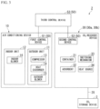
- FIG. 1 is a block diagram showing a resource generation system 1 in Embodiment 1.
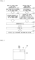
- FIG. 2 is a schematic diagram showing a carbon dioxide recovery system 2 in Embodiment 1.
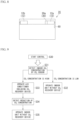
- FIG. 3 is a block diagram showing the carbon dioxide recovery system 2 in Embodiment 1.
- the resource generation system 1 recovers carbon dioxide from air and generates resources (for example, methane) from the recovered carbon dioxide.
- the resource generation system 1 includes a carbon dioxide recovery system 2, a carbon dioxide storage device 3, and a carbon dioxide recycling system 4.
- the carbon dioxide recovery system 2 recovers carbon dioxide from air.
- the carbon dioxide storage device 3 stores the carbon dioxide recovered in the carbon dioxide recovery system.
- the carbon dioxide recycling system 4 is supplied with carbon dioxide from the carbon dioxide storage device 3.
- the carbon dioxide recycling system 4 generates resources from carbon dioxide. Examples of the carbon dioxide recycling system 4 include a methanation system.
- the methanation system has a function of generating methane using carbon dioxide, water, electric power, and the like. It should be noted that the carbon dioxide may be transported between the carbon dioxide storage device 3 and the carbon dioxide recycling system 4, for example, through a pipe, or the carbon dioxide may be transported by an operator.
- the carbon dioxide recovery system 2 includes an air conditioning device 10, a carbon dioxide recovery device 30, and a control device 50.
- the air conditioning device 10 is installed in, for example, a building (such as an office building or an apartment).
- the air conditioning device 10 conditions the air in an indoor space (inside a building, indoors).
- the air conditioning device 10 has functions of cooling, heating, and dehumidifying the indoor space.
- the air conditioning device 10 may be a device having at least one function of cooling, heating, or dehumidification.
- the air conditioning device 10 includes an outdoor unit 11 and an indoor unit 12.
- the refrigerant (thermal medium) circulates between the outdoor unit 11 and the indoor unit 12.
- one indoor unit 12 may be provided for one outdoor unit 11.
- the refrigerant circulates between one outdoor unit 11 and one indoor unit 12.
- a plurality of indoor units 12 may be provided for one outdoor unit 11.
- the refrigerant circulates between one outdoor unit 11 and the plurality of indoor units 12.
- one indoor unit 12 is provided for one outdoor unit 11.
- the outdoor unit 11 includes a compressor 13, a heat exchanger 14, and an outdoor blower 15.
- the compressor 13 compresses the refrigerant to increase its temperature.
- the heat exchanger 14 exchanges heat between the refrigerant and the outside air (air).
- the outdoor blower 15 transfers the outside air, which has been heat-exchanged by the heat exchanger 14, to the outside of the outdoor unit 11.
- the outdoor blower 15 blows air from the inside of the outdoor unit 11 to the outside.
- the indoor unit 12 is installed in a space (indoor space) to be air-conditioned.
- the indoor unit 12 receives supply of a cold energy or thermal energy from the outdoor unit 11 via the refrigerant, and cools, dehumidifies, and heats the indoor space in which each indoor unit 12 is installed.
- Examples of the indoor unit 12 include a ceiling-embedded type that is embedded in a ceiling, a ceiling-suspended type that is suspended from a ceiling, and a wall-mounted type that is mounted on a wall surface. Note that the type of the indoor unit 12 is not particularly limited.
- the indoor unit 12 includes an indoor blower 16.
- the indoor blower 16 transfers the air that has undergone heat exchange with the refrigerant in the indoor unit 12 to the indoor space.
- the indoor blower 16 blows air from the inside of the indoor unit 12 to the outside.
- the outdoor unit 11 may further include an expansion valve that expands the refrigerant, a switching valve that switches a flow direction of the refrigerant, or the like.
- the carbon dioxide recovery device 30 is provided downstream or upstream of the outdoor blower 15 or the indoor blower 16. In other words, the carbon dioxide recovery device 30 is provided in at least one of the following locations: (1) downstream of the outdoor blower 15, (2) upstream of the outdoor blower 15, (3) downstream of the indoor blower 16, or (4) upstream of the indoor blower 16.
- the phrase "(1) downstream of the outdoor blower 15" refers to, for example, a space where air from the outdoor blower 15 is blown when the outdoor blower 15 blows air.
- the phrase "(2) upstream of the outdoor blower 15” refers to, for example, a space where air to be sucked by the outdoor blower 15 is present when the outdoor blower 15 blows air.
- the phrase “(3) downstream of the indoor blower 16” refers to, for example, a space where air from the indoor blower 16 is blown when the indoor blower 16 blows air.
- the phrase “(4) upstream of the indoor blower 16” refers to, for example, a space where air to be sucked by the indoor blower 16 is present when the indoor blower 16 blows air.
- the carbon dioxide recovery system 2 includes a first recovery device 30a and a second recovery device 30b as the carbon dioxide recovery device 30.
- the first recovery device 30a is provided in the outdoor unit 11. It is preferable that the first recovery device 30a can be mounted (retrofitted) to the existing outdoor unit 11, for example.
- the first recovery device 30a is provided (1) downstream of the outdoor blower 15.
- the first recovery device 30a may be provided (2) upstream of the outdoor blower 15.
- the first recovery device 30a may be provided both (1) downstream of the outdoor blower 15 and (2) upstream of the outdoor blower 15.
- the second recovery device 30b is provided in the indoor unit 12. It is preferable that the second recovery device 30b can be mounted (retrofitted) to the existing indoor unit 12, for example.
- the second recovery device 30b is provided (3) downstream of the indoor blower 16.
- the second recovery device 30b may be provided (4) upstream of the indoor blower 16.
- the second recovery device 30b may be provided both (3) downstream of the indoor blower 16 and (4) upstream of the indoor blower 16.
- the first recovery device 30a recovers carbon dioxide using air blowing from the outdoor blower 15.
- the second recovery device 30b recovers carbon dioxide using air blowing from the indoor blower 16. That is, each carbon dioxide recovery device 30 recovers carbon dioxide using the air blowing from either the outdoor blower 15 or the indoor blower 16.
- the carbon dioxide recovery device 30 is not limited to the following example.
- the carbon dioxide recovery device 30 includes a container 31, an adsorbent 32, a switching mechanism 33, and a heat source 34.
- the container 31 has air permeability. Therefore, when the indoor blower 16 or the outdoor blower 15 blows air, the air enters the container 31 or the air inside the container 31 is discharged. That is, the air inside the container 31 and the air outside the container 31 can be exchanged by the air blowing from the indoor blower 16 or the outdoor blower 15.
- the container 31 need only be capable of accommodating the adsorbent 32 and has air permeability.
- adsorbent 32 is granular, a plurality of pores smaller than a particle diameter of the adsorbent 32 may be formed in the container 31.
- the entire container 31 or a part of the container 31 may be mesh.
- a material of the container 31 may be appropriately changed and may be metal or resin. Other structures can also be adopted for the container 31.
- the adsorbent 32 includes a material capable of adsorbing carbon dioxide.
- a material capable of adsorbing carbon dioxide include amine, zeolite, silica gel, diatomaceous earth, alumina, activated carbon, and the like. A plurality of materials may be selected and adopted from the above, or a material other than the above may be adopted.
- the adsorbent 32 may be granular (for example, bead shape (spherical) or pellet shape (cylindrical)).
- a powdery adsorbent 32 may be adopted.
- the powdery adsorbent 32 may be supported on a surface of the base material.
- the base material may have, for example, a honeycomb shape.
- a material in which the carbon dioxide is separated when the adsorbent 32 which has adsorbed the carbon dioxide is heated is preferable. The heating temperature is appropriately changed depending on the specific material of the adsorbent 32.
- the switching mechanism 33 switches the air flow passage (air passage) of the air blown from the outdoor blower 15 or the indoor blower 16.
- the switching mechanism 33 switches, for example, the air passage between a first air passage and a second air passage.
- the air passing through the first air passage has more contact with the adsorbent 32 than the air passing through the second air passage.
- the switching mechanism 33 by switching between the first air passage and the second air passage using the switching mechanism 33, the amount of carbon dioxide to be absorbed is adjusted.
- the air passing through the second air passage may not need to contact the adsorbent 32.
- the switching mechanism 33 include, for example, a movable fan. In this case, for example, the air passage is switched depending on a direction of the fan.
- the heat source 34 supplies a cold energy or thermal energy to the adsorbent 32.
- the heat source 34 for example, generates heat and absorbs heat by receiving power.
- the heat source 34 may supply the cold energy or thermal energy to the adsorbent 32 through, for example, the air blown from the outdoor blower 15 or the indoor blower 16.
- the heat source 34 may supply the cold energy or thermal energy to the adsorbent 32 using, for example, radiation.
- the switching mechanism 33 and the heat source 34 may be omitted.
- the carbon dioxide recovery device 30 is connected to the carbon dioxide storage device 3 via a pipe 35.
- the pipe transfers the carbon dioxide separated from the carbon dioxide recovery device 30 to the carbon dioxide storage device 3.
- the pipe 35 may be omitted.
- the carbon dioxide recovery device 30 can be removable from the air conditioning device 10, and the carbon dioxide is separated from the carbon dioxide recovery device 30 that is removed from the air conditioning device 10.
- the carbon dioxide separated from the carbon dioxide recovery device 30 can be stored in the carbon dioxide storage device 3.
- the container 31 containing the adsorbent 32 may be used as a cartridge, and the container 31 can be removable from, for example, the carbon dioxide recovery device 30 (main body of carbon dioxide recovery device 30).
- the control device 50 controls at least the air conditioning device 10 among the air conditioning device 10 and the carbon dioxide recovery device 30.
- the control device 50 controls both the air conditioning device 10 and the carbon dioxide recovery device 30.
- the control device 50 may not need to control the carbon dioxide recovery device 30.
- the control device 50 includes a first control device 51, a second control device 52, and a third control device 53.
- the first control device 51 is built into the air conditioning device 10 (for example, at least one of the outdoor unit 11 and the indoor unit 12).
- the first control device 51 controls each component of the air conditioning device 10.
- the second control device 52 is built into the carbon dioxide recovery device 30.
- the second control device 52 controls each component of the carbon dioxide recovery device 30.
- the third control device 53 is provided outside the air conditioning device 10 and outside the carbon dioxide recovery device 30.
- the third control device 53 can communicate with the first control device 51 and the second control device 52.
- the third control device 53 controls the first control device 51 and the second control device 52.
- the control device 50 may not include all of the first control device 51, the second control device 52, and the third control device 53.
- the control device 50 may include the first control device 51 and the second control device 52, but may not include the third control device 53.
- the first control device 51 and the second control device 52 may directly communicate with each other.
- the control device 50 may not include the second control device 52 and the third control device 53, although the first control device 51 is provided.
- FIG. 4 is a flow chart showing the carbon dioxide recovery method and resource generation method according to Embodiment 1.
- the carbon dioxide recovery device 30 recovers carbon dioxide using air blowing from the outdoor blower 15 or the indoor blower 16. Further, the carbon dioxide recovery device 30 uses a thermal energy or cold energy of the refrigerant from the air conditioning device 10 as at least part of the heat source for recovering or separating carbon dioxide.
- the air conditioning device 10 (also referred to as an "air conditioner" in the drawing. The same applies to the following drawings.) recovers or separates carbon dioxide using blowing power of the air conditioning device 10 even when the indoor air is not conditioned (for example, when the indoor air is neither heated nor cooled).
- the control device 50 operates at least one of the outdoor blower 15 or the indoor blower 16 in a state where the compressor 13 is stopped (step S11).
- the carbon dioxide recovery device 30 receives the air blown from the outdoor blower 15 and the indoor blower 16, and the carbon dioxide is recovered and separated in the carbon dioxide recovery device 30 that received the air (step S12).
- the control device 50 appropriately controls the heat source 34 of the carbon dioxide recovery device 30 to promote the recovery and separation of carbon dioxide.
- the air conditioning device 10 also recovers or separates carbon dioxide using the blowing power of the air conditioning device 10 even when the air conditioning device 10 conditions the indoor air (for example, when the indoor space is heated or cooled).
- the control device 50 operates both the outdoor blower 15 and the indoor blower 16 in a state where the compressor 13 is in operation (step S13).
- the carbon dioxide recovery device 30 receives the air blown from the outdoor blower 15 and the indoor blower 16, and the carbon dioxide is recovered and separated in the carbon dioxide recovery device 30 that received the air (step S14).
- the air sent from the outdoor blower 15 or the indoor blower 16 to the carbon dioxide recovery device 30 receives a thermal energy or cold energy from the refrigerant, and the temperature thereof is adjusted.
- control device 50 controls at least the air conditioning device 10 among the air conditioning device 10 and the carbon dioxide recovery device 30 such that a thermal energy or cold energy of a refrigerant of the air conditioning device 10 serves as at least a part of a heat source for recovery or separation of carbon dioxide by the carbon dioxide recovery device 30.
- the amount of the thermal energy generated by the heat source 34 of the second recovery device 30b can be reduced by the amount of the thermal energy received by the second recovery device 30b through the air blowing from the indoor blower 16.
- the amount of the cold energy generated by the heat source 34 of the second recovery device 30b can be reduced by the amount of the cold energy received by the second recovery device 30b through the air blowing from the indoor blower 16.
- the amount of the cold energy generated by the heat source 34 of the first recovery device 30a can be reduced by the amount of the cold energy received by the first recovery device 30a through the air blowing from the outdoor blower 15.
- the amount of the thermal energy generated by the heat source 34 of the first recovery device 30a can be reduced by the amount of the thermal energy received by the first recovery device 30a through the air blowing from the outdoor blower 15.
- control device 50 may control the switching mechanism 33.
- the switching mechanism 33 may switch the air passage to the second air passage.
- the control device 50 may control the heat source 34 without controlling the switching mechanism 33, and may further increase the amount of heat supplied by the heat source 34.
- the carbon dioxide recovery device 30 may not recover carbon dioxide even in a case where the air conditioning device 10 conditions the indoor air.
- the control device 50 may control the switching mechanism 33 to switch the air passage to the second air passage.
- the air conditioning device 10 When the air conditioning device 10 is operated by increasing the blowing capacity of at least one of the outdoor blower 15 or the indoor blower 16, more air is blown to the carbon dioxide recovery device 30 than in a case in which the blowing capacity is not increased. Therefore, the carbon dioxide recovery device 30 recovers a greater amount of carbon dioxide.
- the carbon dioxide recovery device 30 recovers carbon dioxide using the air blowing from the outdoor blower 15 or the indoor blower 16. Therefore, in the carbon dioxide recovery device 30 itself, (1) it is not necessary to have power for air blowing, or (2) even in a case where power for the air blowing is provided, a low-capacity power can be adopted as the power. As a result, carbon dioxide can be recovered with a simple structure.
- the air conditioning device 10 when the air conditioning device 10 operates to condition the indoor air, the air conditioning device 10 can be used to not only condition the air but also recover carbon dioxide using the air blowing from the outdoor blower 15 or the indoor blower 16. As a result, carbon dioxide can be recovered with energy savings (less energy).
- the control device 50 operates at least one of the outdoor blower 15 or the indoor blower 16. Therefore, the outdoor blower 15 and the indoor blower 16 can be utilized as power for recovering carbon dioxide even when the air conditioning device 10 does not operate to condition the indoor air.
- the control device 50 operates the air conditioning device 10 in the second operation mode when it had determined to operate the air conditioning device 10 in the first operation mode based on air conditioning conditions and it determines to increase a recovery capacity of carbon dioxide based on a carbon dioxide recovery condition.
- the control device 50 can increase a recovery capacity of the carbon dioxide even during periods when the air conditioning conditions are usually relaxed (for example, intermediate periods such as spring or autumn), which are times when the air conditioning device 10 is normally operated in the first operation mode.
- the thermal energy or cold energy of the refrigerant in the air conditioning device 10 serves as at least a part of a heat source for the recovery or separation of carbon dioxide by the carbon dioxide recovery device 30.
- the carbon dioxide recovery device 30 requires the thermal energy or cold energy, either (1) the carbon dioxide recovery device 30 does not require the thermal energy or cold energy generated by itself, or (2) when the carbon dioxide recovery device 30 itself does generate the thermal energy or cold energy, the amount of generated thermal energy or cold energy can be reduced. As a result, carbon dioxide can be recovered with energy savings.
- the carbon dioxide recovery system 2A further includes a carbon dioxide sensor 60.
- the carbon dioxide sensor 60 measures a carbon dioxide concentration in the indoor space.
- the carbon dioxide sensor 60 is connected to the control device 50.
- the control device 50 operates the indoor blower 16 based on a measurement result of the carbon dioxide sensor 60.
- a first threshold value is stored in the control device 50.
- the first threshold value is a value related to the concentration measured by the carbon dioxide sensor 60. For example, in a case where the carbon dioxide concentration in the indoor space exceeds 1000 ppm, it can generally be said that the carbon dioxide concentration is high.
- the first threshold value may be 1000 ppm.
- the first threshold value is not limited to 1000 ppm and can be appropriately set.
- the general carbon dioxide concentration in the air can be adopted as the first threshold value.
- a value based on the results of pre-verification tests (including not only an actual machine test and a simulation) can also be adopted.
- the control device 50 does not operate the compressor 13 and the like in combination with the indoor blower 16, and does not implement indoor air conditioning.
- the control device 50 may also operate the compressor 13 along with other components, and simultaneously implement indoor air conditioning.
- the control device 50 acquires the carbon dioxide concentration in the indoor space from the carbon dioxide sensor 60 (step S21). In a case where the carbon dioxide concentration is lower than the first threshold value, the control device 50 does not operate the indoor blower 16 (step S22). In this case, the control device 50 continuously acquires the carbon dioxide concentration, and in a case where the carbon dioxide concentration is higher than the first threshold value, the control device 50 executes the next process.
- the control device 50 operates the indoor blower 16 to recover the carbon dioxide using the carbon dioxide recovery device 30 (step S23).
- the blowing power of the indoor blower 16 may be used for the separation from the carbon dioxide recovery device 30.
- the outdoor blower 15 may be operated.
- the control device 50 continuously acquires the carbon dioxide concentration and stops the indoor blower 16 (step S25) in a case where the carbon dioxide concentration is lower than the first threshold value (step S24). Thereafter, the control device 50 continuously acquires the carbon dioxide concentration and repeats the determination and process described above.
- the expressions "a case where the carbon dioxide concentration is lower than the first threshold value” (hereinafter, simply referred to as “low case”) and "a case where the carbon dioxide concentration is higher than the first threshold value” (hereinafter, simply referred to as “high case”) are used.
- the case where the carbon dioxide concentration matches with the first threshold value as long as it is included in only one of the low case or high case, the case may be included in either the low case or high case.
- the air conditioning device 10 includes a plurality of indoor units 12. Each indoor unit 12 is provided with a carbon dioxide recovery device 30.
- the air conditioning device 10 may include one outdoor unit 11 shared by the plurality of indoor units 12.
- Each of the plurality of indoor units 12 of the air conditioning device 10 may individually include the outdoor unit 11.
- the control device 50 operates the first indoor unit 12a to recover the carbon dioxide using the carbon dioxide recovery device 30 (step S33).
- the blowing power of the indoor blower 16 may be used for the separation from the carbon dioxide recovery device 30.
- the control device 50 continuously acquires the carbon dioxide concentration, and in a case where the carbon dioxide concentration becomes lower than the first threshold value (step S34), the second indoor unit 12b is operated instead of the first indoor unit 12a (step S35). Thereafter, the control device 50 continuously acquires the carbon dioxide concentration and repeats the determination and process described above.
- the control device 50 preferentially operates the indoor blower 16 of the first indoor unit 12a in a case where the carbon dioxide concentration is higher than the first threshold value, and preferentially operates the indoor blower 16 of the second indoor unit 12b in a case where the carbon dioxide concentration is lower than the first threshold value.
- the control device 50 preferentially operates the indoor blower 16 of the first indoor unit 12a, and in a case where the carbon dioxide concentration is lower than the first threshold value, the control device 50 preferentially operates the indoor blower 16 of the second indoor unit 12b. Therefore, the amount of carbon dioxide to be recovered by the carbon dioxide recovery device 30 can be adjusted with high accuracy according to the carbon dioxide concentration in the indoor space.
- the carbon dioxide recovery system 2D further includes an infrared sensor 70 instead of the carbon dioxide sensor 60.
- the infrared sensor 70 measures the temperature of the indoor space.
- the carbon dioxide sensor 60 is connected to the control device 50.
- the infrared sensor 70 the infrared sensor 70 built into the indoor unit 12 may be adopted.
- the control device 50 operates the indoor blower 16 based on the measurement result of the infrared sensor 70.
- the control device 50 can estimate the presence or absence of a living organism (such as a person) in the indoor space and the number of living organisms (number of persons) based on the measurement result of the infrared sensor 70.
- the control device 50 determines that the carbon dioxide concentration in the indoor space is high.
- the control device 50 does not operate the compressor 13 and the like in combination with the indoor blower 16, and does not implement indoor air conditioning.
- the control device 50 may also operate the compressor 13 along with other components, and simultaneously implement indoor air conditioning.
- the control device 50 detects the carbon dioxide concentration in the indoor space using the infrared sensor 70 (step S41). In a case where the control device 50 determines that the carbon dioxide concentration is low (absence or small number of persons), the control device 50 does not operate the indoor blower 16 (step S42). In this case, the control device 50 continuously acquires the measurement result from the infrared sensor 70, and in a case where it determines that the carbon dioxide concentration has increased, the control device 50 executes the next process.
- control device 50 determines that the carbon dioxide concentration is high (presence in the indoor space, large number of persons), the control device 50 operates the indoor blower 16 and causes the carbon dioxide recovery device 30 to recover the carbon dioxide (step S43).
- the blowing power of the indoor blower 16 may be used for the separation from the carbon dioxide recovery device 30. Thereafter, the control device 50 continuously acquires the carbon dioxide concentration and repeats the determination and process described above.
- control device 50 can operate the indoor blower 16 based on a detection result of the infrared sensor 70, thereby adjusting the amount of carbon dioxide to be recovered by the carbon dioxide recovery device 30 according to, for example, the presence or absence of living organisms in the indoor space or the number of living organisms.
- the carbon dioxide recovery systems 2, 2A, 2B, 2C, and 2D according to the present embodiment are the carbon dioxide recovery systems 2, 2A, 2B, 2C, and 2D according to any one of the Embodiments 1 to 5 described above.
- a power supply system 80 that supplies power to the carbon dioxide recovery systems 2, 2A, 2B, 2C, and 2D will be described.
- the power supply system 80 includes a power generation system 81 and a storage battery 82.
- the power generation system 81 is a power generation system 81 provided outside the carbon dioxide recovery systems 2, 2A, 2B, 2C, and 2D.
- Examples of the power generation system 81 include a power generation system 81 using renewable energy. Examples of renewable energy include solar power.
- the power generation system 81 is not limited to a power generation system 81 using renewable energy and may also be, for example, a power generation system 81 using thermal power.
- the power generated by the power generation system 81 is referred to as first power.
- the power generation system 81 can supply the first power to both the storage battery 82 and the carbon dioxide recovery systems 2, 2A, 2B, 2C, and 2D.
- the storage battery 82 receives and stores the first power.
- a known configuration can be adopted.
- the power generated by the storage battery 82 is referred to as second power.
- the storage battery 82 can supply the second power to the carbon dioxide recovery systems 2, 2A, 2B, 2C, and 2D.
- the carbon dioxide recovery systems 2, 2A, 2B, 2C, and 2D recover carbon dioxide using the first power during the first period as shown in FIG. 12 , and recover carbon dioxide using the second power during the second period as shown in FIG. 13 .
- the first period includes daytime when the power generation system 81 generates a large amount of power
- the second period includes nighttime when the power generation system 81 generates a small amount of power.
- the determination of daytime and nighttime may be made, for example, based on the amount of daylight or based on the time. It should be noted that the determination of the daytime and nighttime (the determination between the first period and the second period) can be made by, for example, the control device 50.
- the power generation system 81 supplies the first power to both the storage battery 82 and the carbon dioxide recovery systems 2, 2A, 2B, 2C, and 2D.
- the storage battery 82 stores the first power during the first period.
- the power supply from the power generation system 81 to the carbon dioxide recovery systems 2, 2A, 2B, 2C, and 2D is stopped, and the storage battery 82 supplies the second power to the carbon dioxide recovery systems 2, 2A, 2B, 2C, and 2D.
- the power supply system 80 includes a gas generation system 83, a gas storage device 84, and a generator 85, instead of the storage battery 82.
- the gas storage device 84 stores the gas generated by the gas generation system 83.
- the gas storage device 84 may concentrate and store the gas.
- the generator 85 that generates power based on the gas supplied from the gas storage device 84 can supply the generated power to the carbon dioxide recovery systems 2, 2A, 2B, 2C, and 2D.
- the power supplied from the generator 85 is referred to as third power.
- the generator 85 may be a fuel cell (SOFC fuel cell).
- the carbon dioxide recovery systems 2, 2A, 2B, 2C, and 2D recover carbon dioxide using the first power during a third period as shown in FIG. 14 , and recover carbon dioxide using the third power during a fourth period as shown in FIG. 15 .
- the third period includes daytime when the power generation system 81 generates a large amount of power
- the fourth period includes nighttime when the power generation system 81 generates a small amount of power.
- the determination of daytime and nighttime may be made, for example, based on the amount of daylight or based on the time. It should be noted that the determination of the daytime and nighttime (the determination between the third period and the fourth period) can be made by, for example, the control device 50.
- the first power can be stored as power as it is or converted into gas and stored. Then, during other periods such as nighttime (second period and fourth period), carbon dioxide can be recovered using the stored power (second power) or the power generated using the converted gas (third power). Therefore, for example, even in a case where using the power supply from the power generation system 81, in which the amount of power generation varies significantly, such as with renewable energy, carbon dioxide can be stably recovered.
- the control device 50 includes, for example, a computer system.
- a program for realizing the functions of each configuration of the above-described carbon dioxide recovery systems 2, 2A, 2B, 2C, and 2D may be recorded on a computer-readable recording medium, the program recorded on the recording medium may be read into a computer system, and the program may be executed to perform processing in the above-described each component.
- the "the program recorded on the recording medium may be read into a computer system, and the program may be executed” includes installing the program in the computer system.
- computer system described here includes an OS and hardware such as a peripheral device.
- the "computer system” may include a plurality of computer devices connected via a network including a communication line such as the Internet or a WAN, a LAN, and a dedicated line.
- the "computer-readable recording medium” refers to a portable medium such as a flexible disk, a magneto-optical disk, a ROM, and a CD-ROM, and a storage device such as a hard disk built in the computer system.
- the recording medium in which the program is stored may be a non-transitory recording medium such as a CD-ROM.
- the recording medium also includes a recording medium provided internally or externally which is accessible from a distribution server for distributing the program.
- the program may be divided into a plurality of programs and may be downloaded at different timings and then combined by each configuration provided in the carbon dioxide recovery systems 2, 2A, 2B, 2C, and 2D, or a distribution server that distributes each divided program may be different.
- the "computer-readable recording medium” also includes a recording medium that holds the program for a certain period of time such as a volatile memory (RAM) inside the computer system such as a server or a client in a case in which a program is transmitted via a network.
- the program may be a program for realizing some of the functions described above.
- the program may be a so-called difference file (difference program) capable of realizing the functions described above in combination with a program recorded in advance in the computer system.
- each control device 50 All or some of the functions of each control device 50 are realized by using hardware such as an application specific integrated circuit (ASIC), a programmable logic device (PLD), or a field programmable gate array (FPGA).
- ASIC application specific integrated circuit
- PLD programmable logic device
- FPGA field programmable gate array
Landscapes
- Chemical & Material Sciences (AREA)
- Engineering & Computer Science (AREA)
- Combustion & Propulsion (AREA)
- Mechanical Engineering (AREA)
- General Engineering & Computer Science (AREA)
- Chemical Kinetics & Catalysis (AREA)
- Analytical Chemistry (AREA)
- Oil, Petroleum & Natural Gas (AREA)
- Organic Chemistry (AREA)
- General Chemical & Material Sciences (AREA)
- Fluid Mechanics (AREA)
- Physics & Mathematics (AREA)
- Inorganic Chemistry (AREA)
- Carbon And Carbon Compounds (AREA)
- Air Conditioning Control Device (AREA)
- Separation Of Gases By Adsorption (AREA)
Abstract
Description
- The present invention relates to a carbon dioxide recovery system, a resource generation system, and a carbon dioxide recovery method.
- Patent Document 1 discloses a gas removal and concentration device that separates and removes carbon dioxide contained in a treatment target gas from the treatment target gas.
-
Patent Document 1: Japanese Unexamined Patent Application, First Publication JP 2021 94 485 A - In this type of device, power is required to recover carbon dioxide.
- In view of the above circumstances, the present invention is to provide a carbon dioxide recovery system, a resource generation system, and a carbon dioxide recovery method that is capable of recovering carbon dioxide with a simple structure.
- One aspect of the carbon dioxide recovery system according to the present invention includes an air conditioning device including an outdoor unit with a compressor, a heat exchanger, and an outdoor blower, and at least one indoor unit with an indoor blower; and a carbon dioxide recovery device that is provided downstream or upstream of the outdoor blower or the indoor blower and that recovers carbon dioxide using air blowing from the outdoor blower or the indoor blower.
- One aspect of the resource generation system according to the present invention includes the carbon dioxide recovery system, a carbon dioxide storage device that stores the carbon dioxide recovered by the carbon dioxide recovery system, and a carbon dioxide recycling system to which the carbon dioxide is supplied from the carbon dioxide storage device.
- One aspect of the carbon dioxide recovery method according to the present invention is a recovery method of carbon dioxide using the carbon dioxide recovery system, in which the carbon dioxide recovery device recovers carbon dioxide using air blowing from the outdoor blower or the indoor blower.
- According to the present invention, it is possible to provide a carbon dioxide recovery system, a resource generation system, and a carbon dioxide recovery method that is capable of recovering carbon dioxide with a simple structure.
-
-
FIG. 1 Ablock diagram of a resource generation system according to Embodiment 1. -
FIG. 2 A schematic diagram of a carbon dioxide recovery system according to Embodiment 1. -
FIG. 3 A block diagram of the carbon dioxide recovery system according to 1. -
FIG. 4 A flowchart of a carbon dioxide recovery method according to Embodiment 1. -
FIG. 5 Aschematic diagram of a carbon dioxide recovery system according toEmbodiment 2. -
FIG. 6 Aflowchart of a carbon dioxide recovery method according toEmbodiment 2. -
FIG. 7 Aschematic diagram of a carbon dioxide recovery system according toEmbodiment 3. -
FIG. 8 Aschematic diagram of a carbon dioxide recovery system according toEmbodiment 4. -
FIG. 9 Aflowchart of a carbon dioxide recovery method according toEmbodiment 4. -
FIG. 10 Aschematic diagram of a carbon dioxide recovery system according to Embodiment 5. -
FIG. 11 Aflowchart of a carbon dioxide recovery method according to Embodiment 5. -
FIG. 12 Ablock diagram of a carbon dioxide recovery system and a power supply system according to Embodiment 6, and showing a power supply path in a first period. -
FIG. 13 Ablock diagram of the carbon dioxide recovery system and the power supply system according to Embodiment 6, and showing a power supply path in a second period. -
FIG. 14 Ablock diagram of a carbon dioxide recovery system and a power supply system according to Embodiment 7, and showing a power supply path in a third period. -
FIG. 15 Ablock diagram of the carbon dioxide recovery system and the power supply system according to Embodiment 7, and showing a power supply path in a fourth period. - Hereinafter, an Embodiment of the present invention will be described with reference to the drawings. The scope of the present invention is not limited to the following embodiment, and can be changed in any way within the scope of technical ideas of the present invention.
-
FIG. 1 is a block diagram showing a resource generation system 1 in Embodiment 1.FIG. 2 is a schematic diagram showing a carbondioxide recovery system 2 in Embodiment 1.FIG. 3 is a block diagram showing the carbondioxide recovery system 2 in Embodiment 1. - The resource generation system 1 recovers carbon dioxide from air and generates resources (for example, methane) from the recovered carbon dioxide. The resource generation system 1 includes a carbon
dioxide recovery system 2, a carbondioxide storage device 3, and a carbondioxide recycling system 4. - As shown in
FIG. 1 , the carbondioxide recovery system 2 recovers carbon dioxide from air. The carbondioxide storage device 3 stores the carbon dioxide recovered in the carbon dioxide recovery system. The carbondioxide recycling system 4 is supplied with carbon dioxide from the carbondioxide storage device 3. The carbondioxide recycling system 4 generates resources from carbon dioxide. Examples of the carbondioxide recycling system 4 include a methanation system. The methanation system has a function of generating methane using carbon dioxide, water, electric power, and the like. It should be noted that the carbon dioxide may be transported between the carbondioxide storage device 3 and the carbondioxide recycling system 4, for example, through a pipe, or the carbon dioxide may be transported by an operator. - As shown in
FIG. 2 andFIG. 3 , the carbondioxide recovery system 2 includes anair conditioning device 10, a carbondioxide recovery device 30, and acontrol device 50. - The
air conditioning device 10 is installed in, for example, a building (such as an office building or an apartment). Theair conditioning device 10 conditions the air in an indoor space (inside a building, indoors). Theair conditioning device 10 has functions of cooling, heating, and dehumidifying the indoor space. Theair conditioning device 10 may be a device having at least one function of cooling, heating, or dehumidification. - The
air conditioning device 10 includes anoutdoor unit 11 and anindoor unit 12. In theair conditioning device 10, the refrigerant (thermal medium) circulates between theoutdoor unit 11 and theindoor unit 12. It should be noted that oneindoor unit 12 may be provided for oneoutdoor unit 11. In this case, the refrigerant circulates between oneoutdoor unit 11 and oneindoor unit 12. In addition, a plurality ofindoor units 12 may be provided for oneoutdoor unit 11. In this case, the refrigerant circulates between oneoutdoor unit 11 and the plurality ofindoor units 12. In the present embodiment, oneindoor unit 12 is provided for oneoutdoor unit 11. - The
outdoor unit 11 includes acompressor 13, aheat exchanger 14, and anoutdoor blower 15. Thecompressor 13 compresses the refrigerant to increase its temperature. The heat exchanger 14 exchanges heat between the refrigerant and the outside air (air). Theoutdoor blower 15 transfers the outside air, which has been heat-exchanged by theheat exchanger 14, to the outside of theoutdoor unit 11. Theoutdoor blower 15 blows air from the inside of theoutdoor unit 11 to the outside. - The
indoor unit 12 is installed in a space (indoor space) to be air-conditioned. Theindoor unit 12 receives supply of a cold energy or thermal energy from theoutdoor unit 11 via the refrigerant, and cools, dehumidifies, and heats the indoor space in which eachindoor unit 12 is installed. Examples of theindoor unit 12 include a ceiling-embedded type that is embedded in a ceiling, a ceiling-suspended type that is suspended from a ceiling, and a wall-mounted type that is mounted on a wall surface. Note that the type of theindoor unit 12 is not particularly limited. - The
indoor unit 12 includes anindoor blower 16. Theindoor blower 16 transfers the air that has undergone heat exchange with the refrigerant in theindoor unit 12 to the indoor space. Theindoor blower 16 blows air from the inside of theindoor unit 12 to the outside. - Note that a known configuration can be adopted for the
outdoor unit 11 and theindoor unit 12. For example, theoutdoor unit 11 may further include an expansion valve that expands the refrigerant, a switching valve that switches a flow direction of the refrigerant, or the like. - The carbon
dioxide recovery device 30 is provided downstream or upstream of theoutdoor blower 15 or theindoor blower 16. In other words, the carbondioxide recovery device 30 is provided in at least one of the following locations:
(1) downstream of theoutdoor blower 15, (2) upstream of theoutdoor blower 15, (3) downstream of theindoor blower 16, or (4) upstream of theindoor blower 16. - Here, the phrase "(1) downstream of the
outdoor blower 15" refers to, for example, a space where air from theoutdoor blower 15 is blown when theoutdoor blower 15 blows air. The phrase "(2) upstream of theoutdoor blower 15" refers to, for example, a space where air to be sucked by theoutdoor blower 15 is present when theoutdoor blower 15 blows air. The phrase "(3) downstream of theindoor blower 16" refers to, for example, a space where air from theindoor blower 16 is blown when theindoor blower 16 blows air. The phrase "(4) upstream of theindoor blower 16" refers to, for example, a space where air to be sucked by theindoor blower 16 is present when theindoor blower 16 blows air. - In the present embodiment, the carbon
dioxide recovery system 2 includes afirst recovery device 30a and asecond recovery device 30b as the carbondioxide recovery device 30. - The
first recovery device 30a is provided in theoutdoor unit 11. It is preferable that thefirst recovery device 30a can be mounted (retrofitted) to the existingoutdoor unit 11, for example. In the shown example, thefirst recovery device 30a is provided (1) downstream of theoutdoor blower 15. However, thefirst recovery device 30a may be provided (2) upstream of theoutdoor blower 15. Thefirst recovery device 30a may be provided both (1) downstream of theoutdoor blower 15 and (2) upstream of theoutdoor blower 15. - The
second recovery device 30b is provided in theindoor unit 12. It is preferable that thesecond recovery device 30b can be mounted (retrofitted) to the existingindoor unit 12, for example. In the shown example, thesecond recovery device 30b is provided (3) downstream of theindoor blower 16. However, thesecond recovery device 30b may be provided (4) upstream of theindoor blower 16. Thesecond recovery device 30b may be provided both (3) downstream of theindoor blower 16 and (4) upstream of theindoor blower 16. - The
first recovery device 30a recovers carbon dioxide using air blowing from theoutdoor blower 15. Thesecond recovery device 30b recovers carbon dioxide using air blowing from theindoor blower 16. That is, each carbondioxide recovery device 30 recovers carbon dioxide using the air blowing from either theoutdoor blower 15 or theindoor blower 16. - Hereinafter, an example of the carbon
dioxide recovery device 30 will be described. However, the carbondioxide recovery device 30 is not limited to the following example. - The carbon
dioxide recovery device 30 includes acontainer 31, an adsorbent 32, aswitching mechanism 33, and aheat source 34. - The
container 31 has air permeability. Therefore, when theindoor blower 16 or theoutdoor blower 15 blows air, the air enters thecontainer 31 or the air inside thecontainer 31 is discharged. That is, the air inside thecontainer 31 and the air outside thecontainer 31 can be exchanged by the air blowing from theindoor blower 16 or theoutdoor blower 15. - The
container 31 need only be capable of accommodating the adsorbent 32 and has air permeability. For example, in a case where the adsorbent 32 is granular, a plurality of pores smaller than a particle diameter of the adsorbent 32 may be formed in thecontainer 31. Theentire container 31 or a part of thecontainer 31 may be mesh. A material of thecontainer 31 may be appropriately changed and may be metal or resin. Other structures can also be adopted for thecontainer 31. - The adsorbent 32 includes a material capable of adsorbing carbon dioxide. Examples of a material capable of adsorbing carbon dioxide include amine, zeolite, silica gel, diatomaceous earth, alumina, activated carbon, and the like. A plurality of materials may be selected and adopted from the above, or a material other than the above may be adopted. The adsorbent 32 may be granular (for example, bead shape (spherical) or pellet shape (cylindrical)).
- Alternatively, a
powdery adsorbent 32 may be adopted. In this case, thepowdery adsorbent 32 may be supported on a surface of the base material. The base material may have, for example, a honeycomb shape. As the adsorbent 32, a material in which the carbon dioxide is separated when the adsorbent 32 which has adsorbed the carbon dioxide is heated (for example, 60 °C to 120 °C) is preferable. The heating temperature is appropriately changed depending on the specific material of the adsorbent 32. - The
switching mechanism 33 switches the air flow passage (air passage) of the air blown from theoutdoor blower 15 or theindoor blower 16. Theswitching mechanism 33 switches, for example, the air passage between a first air passage and a second air passage. The air passing through the first air passage has more contact with the adsorbent 32 than the air passing through the second air passage. - In this case, by switching between the first air passage and the second air passage using the
switching mechanism 33, the amount of carbon dioxide to be absorbed is adjusted. The air passing through the second air passage may not need to contact the adsorbent 32. Examples of theswitching mechanism 33 include, for example, a movable fan. In this case, for example, the air passage is switched depending on a direction of the fan. - The
heat source 34 supplies a cold energy or thermal energy to the adsorbent 32. Theheat source 34, for example, generates heat and absorbs heat by receiving power. Theheat source 34 may supply the cold energy or thermal energy to the adsorbent 32 through, for example, the air blown from theoutdoor blower 15 or theindoor blower 16. Theheat source 34 may supply the cold energy or thermal energy to the adsorbent 32 using, for example, radiation. - The
switching mechanism 33 and theheat source 34 may be omitted. - The carbon
dioxide recovery device 30 is connected to the carbondioxide storage device 3 via apipe 35. The pipe transfers the carbon dioxide separated from the carbondioxide recovery device 30 to the carbondioxide storage device 3. Thepipe 35 may be omitted. In this case, for example, the carbondioxide recovery device 30 can be removable from theair conditioning device 10, and the carbon dioxide is separated from the carbondioxide recovery device 30 that is removed from theair conditioning device 10. - As a result, the carbon dioxide separated from the carbon
dioxide recovery device 30 can be stored in the carbondioxide storage device 3. In this case, in the carbondioxide recovery device 30, thecontainer 31 containing the adsorbent 32 may be used as a cartridge, and thecontainer 31 can be removable from, for example, the carbon dioxide recovery device 30 (main body of carbon dioxide recovery device 30). - The
control device 50 controls at least theair conditioning device 10 among theair conditioning device 10 and the carbondioxide recovery device 30. In the present embodiment, thecontrol device 50 controls both theair conditioning device 10 and the carbondioxide recovery device 30. However, for example, in a case where the carbondioxide recovery device 30 does not include theswitching mechanism 33, theheat source 34, or the like, in other words, in a case where the carbondioxide recovery device 30 is configured such that the adsorbent 32 is simply accommodated in thecontainer 31, thecontrol device 50 may not need to control the carbondioxide recovery device 30. - In the present embodiment, the
control device 50 includes afirst control device 51, a second control device 52, and athird control device 53. Thefirst control device 51 is built into the air conditioning device 10 (for example, at least one of theoutdoor unit 11 and the indoor unit 12). Thefirst control device 51 controls each component of theair conditioning device 10. The second control device 52 is built into the carbondioxide recovery device 30. - The second control device 52 controls each component of the carbon
dioxide recovery device 30. Thethird control device 53 is provided outside theair conditioning device 10 and outside the carbondioxide recovery device 30. Thethird control device 53 can communicate with thefirst control device 51 and the second control device 52. Thethird control device 53 controls thefirst control device 51 and the second control device 52. - The
control device 50 may not include all of thefirst control device 51, the second control device 52, and thethird control device 53. For example, thecontrol device 50 may include thefirst control device 51 and the second control device 52, but may not include thethird control device 53. In this case, thefirst control device 51 and the second control device 52 may directly communicate with each other. For example, in a case where the carbondioxide recovery device 30 has a configuration in which the adsorbent 32 is simply accommodated in thecontainer 31, thecontrol device 50 may not include the second control device 52 and thethird control device 53, although thefirst control device 51 is provided. - The carbon dioxide recovery method according to the present embodiment uses the aforementioned carbon
dioxide recovery system 2.FIG. 4 is a flow chart showing the carbon dioxide recovery method and resource generation method according to Embodiment 1. - As shown in
FIG. 4 , in the carbon dioxide recovery method according to the present embodiment, the carbondioxide recovery device 30 recovers carbon dioxide using air blowing from theoutdoor blower 15 or theindoor blower 16. Further, the carbondioxide recovery device 30 uses a thermal energy or cold energy of the refrigerant from theair conditioning device 10 as at least part of the heat source for recovering or separating carbon dioxide. - For example, in the present embodiment, the air conditioning device 10 (also referred to as an "air conditioner" in the drawing. The same applies to the following drawings.) recovers or separates carbon dioxide using blowing power of the
air conditioning device 10 even when the indoor air is not conditioned (for example, when the indoor air is neither heated nor cooled). In this case, thecontrol device 50 operates at least one of theoutdoor blower 15 or theindoor blower 16 in a state where thecompressor 13 is stopped (step S11). - In this case, the carbon
dioxide recovery device 30 receives the air blown from theoutdoor blower 15 and theindoor blower 16, and the carbon dioxide is recovered and separated in the carbondioxide recovery device 30 that received the air (step S12). In this case, it is preferable that thecontrol device 50 appropriately controls theheat source 34 of the carbondioxide recovery device 30 to promote the recovery and separation of carbon dioxide. - Further, in the present embodiment, the
air conditioning device 10 also recovers or separates carbon dioxide using the blowing power of theair conditioning device 10 even when theair conditioning device 10 conditions the indoor air (for example, when the indoor space is heated or cooled). In this case, thecontrol device 50 operates both theoutdoor blower 15 and theindoor blower 16 in a state where thecompressor 13 is in operation (step S13). - In this case, the carbon
dioxide recovery device 30 receives the air blown from theoutdoor blower 15 and theindoor blower 16, and the carbon dioxide is recovered and separated in the carbondioxide recovery device 30 that received the air (step S14). The air sent from theoutdoor blower 15 or theindoor blower 16 to the carbondioxide recovery device 30 receives a thermal energy or cold energy from the refrigerant, and the temperature thereof is adjusted. - Therefore, in the present embodiment, it is preferable that the
control device 50 controls at least theair conditioning device 10 among theair conditioning device 10 and the carbondioxide recovery device 30 such that a thermal energy or cold energy of a refrigerant of theair conditioning device 10 serves as at least a part of a heat source for recovery or separation of carbon dioxide by the carbondioxide recovery device 30. - For example, in a case where the
heat source 34 of thesecond recovery device 30b (the carbondioxide recovery device 30 provided in the indoor unit 12) needs to generate a thermal energy and theair conditioning device 10 is in heating mode, the amount of the thermal energy generated by theheat source 34 of thesecond recovery device 30b can be reduced by the amount of the thermal energy received by thesecond recovery device 30b through the air blowing from theindoor blower 16. - Additionally, in a case where the
heat source 34 of thesecond recovery device 30b needs to generate a cold energy and theair conditioning device 10 is in cooling mode, the amount of the cold energy generated by theheat source 34 of thesecond recovery device 30b can be reduced by the amount of the cold energy received by thesecond recovery device 30b through the air blowing from theindoor blower 16. - For example, in a case where the
heat source 34 of thefirst recovery device 30a (the carbondioxide recovery device 30 provided in the outdoor unit 11) needs to generate a thermal energy and theair conditioning device 10 is in heating mode, the amount of the cold energy generated by theheat source 34 of thefirst recovery device 30a can be reduced by the amount of the cold energy received by thefirst recovery device 30a through the air blowing from theoutdoor blower 15. - Additionally, in a case where the
heat source 34 of thefirst recovery device 30a needs to generate a thermal energy and theair conditioning device 10 is in cooling mode, the amount of the thermal energy generated by theheat source 34 of thefirst recovery device 30a can be reduced by the amount of the thermal energy received by thefirst recovery device 30a through the air blowing from theoutdoor blower 15. - It should be noted that, in a case where the
heat source 34 of thesecond recovery device 30b needs to generate a thermal energy and theair conditioning device 10 is in cooling mode, when the amount of heat required by the carbondioxide recovery device 30 and the amount of heat supplied to the carbondioxide recovery device 30 by theair conditioning device 10 have their positive and negative signs inverted, for example, thecontrol device 50 may control theswitching mechanism 33. - In this case, for example, the
switching mechanism 33 may switch the air passage to the second air passage. In addition, in a case where the positive and negative signs of the amount of heat are inverted as described above, thecontrol device 50 may control theheat source 34 without controlling theswitching mechanism 33, and may further increase the amount of heat supplied by theheat source 34. - Here, in the present embodiment, the carbon
dioxide recovery device 30 may not recover carbon dioxide even in a case where theair conditioning device 10 conditions the indoor air. In this case, for example, thecontrol device 50 may control theswitching mechanism 33 to switch the air passage to the second air passage. - In addition, in the present embodiment, the
air conditioning device 10 may recover or separate carbon dioxide using the thermal energy or cold energy from the refrigerant of theair conditioning device 10 even when theair conditioning device 10 does not condition the indoor air (for example, when the indoor space is neither heated nor cooled). In this case, for example, thecontrol device 50 may operate thecompressor 13 in a state where theoutdoor blower 15 and theindoor blower 16 are stopped, and may circulate the refrigerant between theindoor unit 12 and the outdoor unit 11 (so-called defrosting operation or the like). - Further, in the present embodiment, the
control device 50 may control theair conditioning device 10 as follows. - In the present embodiment, the
control device 50 can operate theair conditioning device 10 in the first operation mode or the second operation mode. Theair conditioning device 10, which is operated in the first operation mode, operates at a capacity lower than the rated capacity of theair conditioning device 10. Theair conditioning device 10, which is operated in the second operation mode, operates by increasing a blowing capacity of at least one of theoutdoor blower 15 or theindoor blower 16 compared to when it is operated in the first operation mode. - When the
air conditioning device 10 is operated by increasing the blowing capacity of at least one of theoutdoor blower 15 or theindoor blower 16, more air is blown to the carbondioxide recovery device 30 than in a case in which the blowing capacity is not increased. Therefore, the carbondioxide recovery device 30 recovers a greater amount of carbon dioxide. - The
control device 50 may operate theair conditioning device 10 in the second operation mode when it had determined to operate theair conditioning device 10 in the first operation mode based on air conditioning conditions and it determines to increase a recovery capacity of carbon dioxide based on a carbon dioxide recovery condition. - The
control device 50 selects the operation mode based on the air conditioning conditions. The air conditioning conditions are set based on, for example, a target temperature, a room temperature, a rotational speed of the motor of theoutdoor blower 15 or a rotational speed of the motor of the indoor blower 16 (hereinafter, these may be collectively referred to as rotational speed), a pressure of the refrigerant, and the like. For example, thecontrol device 50 acquires the target temperature by receiving an input from the user. For example, thecontrol device 50 acquires the room temperature from a temperature sensor. - For example, the
control device 50 acquires the rotational speed from theoutdoor blower 15 and theindoor blower 16. For example, thecontrol device 50 acquires the pressure of the refrigerant from a pressure sensor provided in a circulation path of the refrigerant. For example, thecontrol device 50 acquires the rotational speed and the pressure of the refrigerant over time until the room temperature reaches the target temperature, and estimates a load of theair conditioning device 10. In this case, thecontrol device 50 may further acquire, for example, other indicators (information). In this case, thecontrol device 50 may not acquire, for example, some or all of the target temperature, the room temperature, the rotational speed, and the pressure of the refrigerant. Thecontrol device 50 selects a preferred operation mode from the plurality of operation modes based on the estimated load of theair conditioning device 10. - Even when it had determined to operate the
air conditioning device 10 in the first operation mode based on such air conditioning conditions, thecontrol device 50 may intentionally operate theair conditioning device 10 in the second operation mode when it determines to increase a recovery capacity of carbon dioxide based on a carbon dioxide recovery condition. - Examples of the conditions for recovering carbon dioxide considered by the
control device 50 include the season (time) in regions with seasonal variations, such as Japan. For example, during intermediate periods (spring and autumn) when the air conditioning load is smaller compared to summer or winter, there is a risk that the amount of carbon dioxide to be recovered may decrease along with the reduction in the air conditioning load. Therefore, thecontrol device 50 may intentionally operate theair conditioning device 10 in the second operation mode based on information about the season (for example, when it is determined that the current time falls within the intermediate period). - In this case, in a case where there is a concern that the
air conditioning device 10 may supply an excessive cold energy or thermal energy to the indoor space, for example, thecontrol device 50 may control the pressure (temperature) of the refrigerant by thecompressor 13 to appropriately adjust the cold energy or thermal energy. It should be noted that the conditions for recovering carbon dioxide considered by thecontrol device 50 may include not only long-term variations but also short-term variations, such as those occurring during daytime or nighttime. - The carbon dioxide recovered by the above-described recovery method is concentrated (step S15) and stored in the carbon dioxide storage device 3 (step S16). Thereafter, the carbon dioxide is transferred from the carbon
dioxide storage device 3 to the carbon dioxide recycling system 4 (methanation system) and is recycled as a resource such as methane. - As described above, with the carbon
dioxide recovery system 2 according to the present embodiment, the carbondioxide recovery device 30 recovers carbon dioxide using the air blowing from theoutdoor blower 15 or theindoor blower 16. Therefore, in the carbondioxide recovery device 30 itself, (1) it is not necessary to have power for air blowing, or (2) even in a case where power for the air blowing is provided, a low-capacity power can be adopted as the power. As a result, carbon dioxide can be recovered with a simple structure. - Further, when the
air conditioning device 10 operates to condition the indoor air, theair conditioning device 10 can be used to not only condition the air but also recover carbon dioxide using the air blowing from theoutdoor blower 15 or theindoor blower 16. As a result, carbon dioxide can be recovered with energy savings (less energy). - In a state where the
compressor 13 is stopped, thecontrol device 50 operates at least one of theoutdoor blower 15 or theindoor blower 16. Therefore, theoutdoor blower 15 and theindoor blower 16 can be utilized as power for recovering carbon dioxide even when theair conditioning device 10 does not operate to condition the indoor air. - The
control device 50 operates theair conditioning device 10 in the second operation mode when it had determined to operate theair conditioning device 10 in the first operation mode based on air conditioning conditions and it determines to increase a recovery capacity of carbon dioxide based on a carbon dioxide recovery condition. As a result, thecontrol device 50 can increase a recovery capacity of the carbon dioxide even during periods when the air conditioning conditions are usually relaxed (for example, intermediate periods such as spring or autumn), which are times when theair conditioning device 10 is normally operated in the first operation mode. - The thermal energy or cold energy of the refrigerant in the
air conditioning device 10 serves as at least a part of a heat source for the recovery or separation of carbon dioxide by the carbondioxide recovery device 30. As a result, even when the carbondioxide recovery device 30 requires the thermal energy or cold energy, either (1) the carbondioxide recovery device 30 does not require the thermal energy or cold energy generated by itself, or (2) when the carbondioxide recovery device 30 itself does generate the thermal energy or cold energy, the amount of generated thermal energy or cold energy can be reduced. As a result, carbon dioxide can be recovered with energy savings. - Next, the carbon
dioxide recovery system 2A according toEmbodiment 2 will be described. Since the basic configuration of the carbondioxide recovery system 2A according to the present Embodiment is the same as that of Embodiment 1, the differences will be mainly described. - In the present embodiment, as shown in
FIG. 5 , the carbondioxide recovery system 2A further includes acarbon dioxide sensor 60. Thecarbon dioxide sensor 60 measures a carbon dioxide concentration in the indoor space. Thecarbon dioxide sensor 60 is connected to thecontrol device 50. - In the present embodiment, the
control device 50 operates theindoor blower 16 based on a measurement result of thecarbon dioxide sensor 60. A first threshold value is stored in thecontrol device 50. The first threshold value is a value related to the concentration measured by thecarbon dioxide sensor 60. For example, in a case where the carbon dioxide concentration in the indoor space exceeds 1000 ppm, it can generally be said that the carbon dioxide concentration is high. - Therefore, the first threshold value may be 1000 ppm. Note that the first threshold value is not limited to 1000 ppm and can be appropriately set. For example, the general carbon dioxide concentration in the air can be adopted as the first threshold value. As the first threshold value, a value based on the results of pre-verification tests (including not only an actual machine test and a simulation) can also be adopted.
- Next, a carbon dioxide recovery method using the carbon
dioxide recovery system 2A according to the present embodiment will be described. In this recovery method, thecontrol device 50 does not operate thecompressor 13 and the like in combination with theindoor blower 16, and does not implement indoor air conditioning. However, thecontrol device 50 may also operate thecompressor 13 along with other components, and simultaneously implement indoor air conditioning. - As shown in
FIG. 6 , thecontrol device 50 acquires the carbon dioxide concentration in the indoor space from the carbon dioxide sensor 60 (step S21). In a case where the carbon dioxide concentration is lower than the first threshold value, thecontrol device 50 does not operate the indoor blower 16 (step S22). In this case, thecontrol device 50 continuously acquires the carbon dioxide concentration, and in a case where the carbon dioxide concentration is higher than the first threshold value, thecontrol device 50 executes the next process. - In a case where the carbon dioxide concentration is higher than the first threshold value, the
control device 50 operates theindoor blower 16 to recover the carbon dioxide using the carbon dioxide recovery device 30 (step S23). In this case, the blowing power of theindoor blower 16 may be used for the separation from the carbondioxide recovery device 30. In addition, at this time, theoutdoor blower 15 may be operated. Thecontrol device 50 continuously acquires the carbon dioxide concentration and stops the indoor blower 16 (step S25) in a case where the carbon dioxide concentration is lower than the first threshold value (step S24). Thereafter, thecontrol device 50 continuously acquires the carbon dioxide concentration and repeats the determination and process described above. - In the present embodiment and the following embodiments, the expressions "a case where the carbon dioxide concentration is lower than the first threshold value" (hereinafter, simply referred to as "low case") and "a case where the carbon dioxide concentration is higher than the first threshold value" (hereinafter, simply referred to as "high case") are used. In a case where the carbon dioxide concentration matches with the first threshold value, as long as it is included in only one of the low case or high case, the case may be included in either the low case or high case.
- Next, the carbon
dioxide recovery system 2B according toEmbodiment 3 will be described. Since the basic configuration of the carbondioxide recovery system 2B according to the present embodiment is the same as that ofEmbodiment 2, the differences will be mainly described. - As shown in
FIG. 7 , in the carbondioxide recovery system 2B according to the present embodiment, theair conditioning device 10 includes a plurality ofindoor units 12. Eachindoor unit 12 is provided with a carbondioxide recovery device 30. Theair conditioning device 10 may include oneoutdoor unit 11 shared by the plurality ofindoor units 12. Each of the plurality ofindoor units 12 of theair conditioning device 10 may individually include theoutdoor unit 11. - In the carbon dioxide recovery method using the carbon
dioxide recovery system 2B according to the present embodiment, for example, thecontrol device 50 may vary the number ofindoor blowers 16 to be operated (the number ofindoor units 12 to be operated) in accordance with the carbon dioxide concentration. - Next, the carbon
dioxide recovery system 2C according toEmbodiment 4 will be described. Since the basic configuration of the carbondioxide recovery system 2C according to the present embodiment is the same as that ofEmbodiment 3, the differences will be mainly described. - As shown in
FIG. 8 , in the carbondioxide recovery system 2C according to the present embodiment, theair conditioning device 10 includes a firstindoor unit 12a and a secondindoor unit 12b as theindoor units 12. The firstindoor unit 12a is anindoor unit 12 provided with a carbondioxide recovery device 30. The secondindoor unit 12b is anindoor unit 12 in which the carbondioxide recovery device 30 is not provided. - Next, a carbon dioxide recovery method using the carbon
dioxide recovery system 2C according to the present Embodiment will be described. In this recovery method, thecontrol device 50 executes the recovery method, for example, when an input to start the air conditioning is received from the user (step S30). - As shown in
FIG. 9 , thecontrol device 50 acquires the carbon dioxide concentration in the indoor space from the carbon dioxide sensor 60 (step S31). In a case where the carbon dioxide concentration is lower than the first threshold value, thecontrol device 50 operates the secondindoor unit 12b (step S32). In this case, when thecontrol device 50 determines to operate moreindoor units 12 based on the air conditioning conditions, the firstindoor unit 12a may be operated. - In a case where the carbon dioxide concentration is higher than the first threshold value, the
control device 50 operates the firstindoor unit 12a to recover the carbon dioxide using the carbon dioxide recovery device 30 (step S33). In this case, the blowing power of theindoor blower 16 may be used for the separation from the carbondioxide recovery device 30. Thecontrol device 50 continuously acquires the carbon dioxide concentration, and in a case where the carbon dioxide concentration becomes lower than the first threshold value (step S34), the secondindoor unit 12b is operated instead of the firstindoor unit 12a (step S35). Thereafter, thecontrol device 50 continuously acquires the carbon dioxide concentration and repeats the determination and process described above. - As described above, in the carbon dioxide recovery method according to the present embodiment, the
control device 50 preferentially operates theindoor blower 16 of the firstindoor unit 12a in a case where the carbon dioxide concentration is higher than the first threshold value, and preferentially operates theindoor blower 16 of the secondindoor unit 12b in a case where the carbon dioxide concentration is lower than the first threshold value. - As described above, with the carbon
dioxide recovery systems Embodiments 2 to 4, thecontrol device 50 operates theindoor blower 16 based on the measurement results of thecarbon dioxide sensor 60. Therefore, the amount of carbon dioxide to be recovered by the carbondioxide recovery device 30 can be changed according to the carbon dioxide concentration in the indoor space. - In a case where the carbon dioxide concentration is higher than the first threshold value, the
control device 50 preferentially operates theindoor blower 16 of the firstindoor unit 12a, and in a case where the carbon dioxide concentration is lower than the first threshold value, thecontrol device 50 preferentially operates theindoor blower 16 of the secondindoor unit 12b. Therefore, the amount of carbon dioxide to be recovered by the carbondioxide recovery device 30 can be adjusted with high accuracy according to the carbon dioxide concentration in the indoor space. - Next, the carbon
dioxide recovery system 2D according to Embodiment 5 will be described. Since the basic configuration of the carbondioxide recovery system 2D according to the present embodiment is the same as that ofEmbodiment 2, the differences will be mainly described. - In the present embodiment, as shown in
FIG. 10 , the carbondioxide recovery system 2D further includes aninfrared sensor 70 instead of thecarbon dioxide sensor 60. Theinfrared sensor 70 measures the temperature of the indoor space. Thecarbon dioxide sensor 60 is connected to thecontrol device 50. As theinfrared sensor 70, theinfrared sensor 70 built into theindoor unit 12 may be adopted. - In the present embodiment, the
control device 50 operates theindoor blower 16 based on the measurement result of theinfrared sensor 70. For example, thecontrol device 50 can estimate the presence or absence of a living organism (such as a person) in the indoor space and the number of living organisms (number of persons) based on the measurement result of theinfrared sensor 70. In a case where a living organism is present in the indoor space (presence in the indoor space) or the number of living organisms is large (large number of persons), thecontrol device 50 determines that the carbon dioxide concentration in the indoor space is high. - Next, a carbon dioxide recovery method using the carbon
dioxide recovery system 2D according to the present Embodiment will be described. In this recovery method, thecontrol device 50 does not operate thecompressor 13 and the like in combination with theindoor blower 16, and does not implement indoor air conditioning. However, thecontrol device 50 may also operate thecompressor 13 along with other components, and simultaneously implement indoor air conditioning. - As shown in
FIG. 11 , thecontrol device 50 detects the carbon dioxide concentration in the indoor space using the infrared sensor 70 (step S41). In a case where thecontrol device 50 determines that the carbon dioxide concentration is low (absence or small number of persons), thecontrol device 50 does not operate the indoor blower 16 (step S42). In this case, thecontrol device 50 continuously acquires the measurement result from theinfrared sensor 70, and in a case where it determines that the carbon dioxide concentration has increased, thecontrol device 50 executes the next process. - In a case where the
control device 50 determines that the carbon dioxide concentration is high (presence in the indoor space, large number of persons), thecontrol device 50 operates theindoor blower 16 and causes the carbondioxide recovery device 30 to recover the carbon dioxide (step S43). In this case, the blowing power of theindoor blower 16 may be used for the separation from the carbondioxide recovery device 30. Thereafter, thecontrol device 50 continuously acquires the carbon dioxide concentration and repeats the determination and process described above. - As described above, with the carbon
dioxide recovery system 2D according to the present embodiment, thecontrol device 50 can operate theindoor blower 16 based on a detection result of theinfrared sensor 70, thereby adjusting the amount of carbon dioxide to be recovered by the carbondioxide recovery device 30 according to, for example, the presence or absence of living organisms in the indoor space or the number of living organisms. - Next, the carbon dioxide recovery method according to Embodiment 6 will be described. It is preferable that the carbon
dioxide recovery systems dioxide recovery systems - In the present embodiment, first, a
power supply system 80 that supplies power to the carbondioxide recovery systems - As shown in
FIGS. 12 and 13 , thepower supply system 80 includes apower generation system 81 and astorage battery 82. - The
power generation system 81 is apower generation system 81 provided outside the carbondioxide recovery systems power generation system 81 include apower generation system 81 using renewable energy. Examples of renewable energy include solar power. However, thepower generation system 81 is not limited to apower generation system 81 using renewable energy and may also be, for example, apower generation system 81 using thermal power. Hereinafter, the power generated by thepower generation system 81 is referred to as first power. Thepower generation system 81 can supply the first power to both thestorage battery 82 and the carbondioxide recovery systems - The
storage battery 82 receives and stores the first power. As thestorage battery 82, a known configuration can be adopted. Hereinafter, the power generated by thestorage battery 82 is referred to as second power. Thestorage battery 82 can supply the second power to the carbondioxide recovery systems - Next, a carbon dioxide recovery method according to the present embodiment will be described. In this recovery method, the carbon
dioxide recovery systems FIG. 12 , and recover carbon dioxide using the second power during the second period as shown inFIG. 13 . For example, in a case where thepower generation system 81 is apower generation system 81 using solar power, the first period includes daytime when thepower generation system 81 generates a large amount of power, and the second period includes nighttime when thepower generation system 81 generates a small amount of power. - The determination of daytime and nighttime may be made, for example, based on the amount of daylight or based on the time. It should be noted that the determination of the daytime and nighttime (the determination between the first period and the second period) can be made by, for example, the
control device 50. - In the present embodiment, as shown in
FIG. 12 , during the first period, thepower generation system 81 supplies the first power to both thestorage battery 82 and the carbondioxide recovery systems storage battery 82 stores the first power during the first period. In the second period, the power supply from thepower generation system 81 to the carbondioxide recovery systems storage battery 82 supplies the second power to the carbondioxide recovery systems - Next, the carbon dioxide recovery method according to Embodiment 7 will be described. Since the basic configuration of the carbon dioxide recovery method according to the present embodiment is the same as that of Embodiment 6, the carbon dioxide recovery method will be described with reference to the differences.
- In the present embodiment, as shown in
FIGS. 14 and 15 , thepower supply system 80 includes agas generation system 83, agas storage device 84, and agenerator 85, instead of thestorage battery 82. - The
gas generation system 83 and thegas storage device 84 convert the first power into gas and store the gas. - The
gas generation system 83 generates gas by receiving the supply of the first power. Examples of the gas include hydrogen, methane, and the like. - The
gas storage device 84 stores the gas generated by thegas generation system 83. Thegas storage device 84 may concentrate and store the gas. - The
generator 85 that generates power based on the gas supplied from thegas storage device 84 can supply the generated power to the carbondioxide recovery systems generator 85 is referred to as third power. - It should be noted that a well-known configuration is appropriately adopted for the
gas generation system 83, thegas storage device 84, and thegenerator 85. For example, thegenerator 85 may be a fuel cell (SOFC fuel cell). - Next, a carbon dioxide recovery method according to the present Embodiment will be described. In this recovery method, the carbon
dioxide recovery systems FIG. 14 , and recover carbon dioxide using the third power during a fourth period as shown inFIG. 15 . For example, in a case where thepower generation system 81 is apower generation system 81 using solar power, the third period includes daytime when thepower generation system 81 generates a large amount of power, and the fourth period includes nighttime when thepower generation system 81 generates a small amount of power. The determination of daytime and nighttime may be made, for example, based on the amount of daylight or based on the time. It should be noted that the determination of the daytime and nighttime (the determination between the third period and the fourth period) can be made by, for example, thecontrol device 50. - In the present embodiment, as shown in
FIG. 14 , during the third period, thepower generation system 81 supplies the first power to both thegas generation system 83 and the carbondioxide recovery systems gas generation system 83 converts the first power into gas during the third period and stores the gas in thegas storage device 84. In the fourth period, the power supply from thepower generation system 81 to the carbondioxide recovery systems generator 85 supplies the third power to the carbondioxide recovery systems - As described above, with the carbon dioxide recovery method according to Embodiments 6 and 7, for example, during specific periods such as daytime (first period and third period), the first power can be stored as power as it is or converted into gas and stored. Then, during other periods such as nighttime (second period and fourth period), carbon dioxide can be recovered using the stored power (second power) or the power generated using the converted gas (third power). Therefore, for example, even in a case where using the power supply from the
power generation system 81, in which the amount of power generation varies significantly, such as with renewable energy, carbon dioxide can be stably recovered. - However, the technical scope of the present invention is not limited to the above embodiments, and various modifications can be made without departing from the gist of the present invention.
- The
control device 50 includes, for example, a computer system. A program for realizing the functions of each configuration of the above-described carbondioxide recovery systems - In addition, the "computer system" may include a plurality of computer devices connected via a network including a communication line such as the Internet or a WAN, a LAN, and a dedicated line. In addition, the "computer-readable recording medium" refers to a portable medium such as a flexible disk, a magneto-optical disk, a ROM, and a CD-ROM, and a storage device such as a hard disk built in the computer system. As described above, the recording medium in which the program is stored may be a non-transitory recording medium such as a CD-ROM.
- In addition, the recording medium also includes a recording medium provided internally or externally which is accessible from a distribution server for distributing the program. It should be noted that the program may be divided into a plurality of programs and may be downloaded at different timings and then combined by each configuration provided in the carbon
dioxide recovery systems - Further, the "computer-readable recording medium" also includes a recording medium that holds the program for a certain period of time such as a volatile memory (RAM) inside the computer system such as a server or a client in a case in which a program is transmitted via a network. In addition, the program may be a program for realizing some of the functions described above. Further, the program may be a so-called difference file (difference program) capable of realizing the functions described above in combination with a program recorded in advance in the computer system.
- All or some of the functions of each
control device 50 are realized by using hardware such as an application specific integrated circuit (ASIC), a programmable logic device (PLD), or a field programmable gate array (FPGA). - In addition, the above-described embodiments or modification examples may be appropriately combined.
-
- 1:
- Resource generation system
- 2, 2A, 2B, 2C, 2D:
- Carbon dioxide recovery system
- 3:
- Carbon dioxide storage device
- 4:
- Carbon dioxide recycling system
- 10:
- Air conditioning device
- 11:
- Outdoor unit
- 12:
- Indoor unit
- 12a:
- First indoor unit
- 12b:
- Second indoor unit
- 13:
- Compressor
- 14:
- Heat exchanger
- 15:
- Outdoor blower
- 16:
- Indoor blower
- 30:
- Carbon dioxide recovery device
- 50:
- Control device
- 60:
- Carbon dioxide sensor
- 70:
- Infrared sensor
- 81:
- Power generation system
- 82:
- Storage battery
- 85:
- Generator
Claims (16)
- A carbon dioxide recovery system comprising:an air conditioning device including: an outdoor unit with a compressor, a heat exchanger, and an outdoor blower; and at least one indoor unit with an indoor blower; anda carbon dioxide recovery device that is provided downstream or upstream of the outdoor blower or the indoor blower, and that recovers carbon dioxide using air blowing from the outdoor blower or the indoor blower.
- The carbon dioxide recovery system according to Claim 1,
further comprising:
a control device that is configured to control at least the air conditioning device among the air conditioning device and the carbon dioxide recovery device. - The carbon dioxide recovery system according to Claim 2,
wherein the control device operates at least one of the outdoor blower or the indoor blower in a state where the compressor is stopped. - The carbon dioxide recovery system according to Claim 2 or 3,wherein the control device operates the air conditioning device in a first operation mode or a second operation mode,the air conditioning device operated in the first operation mode operates at a capacity lower than a rated capacity of the air conditioning device,the air conditioning device operated in the second operation mode operates by increasing a blowing capacity of at least one of the outdoor blower or the indoor blower compared to when the air conditioning device is operated in the first operation mode, andthe control device operates the air conditioning device in the second operation mode in case where the control device had determined to operate the air conditioning device in the first operation mode based on air conditioning conditions and the control device determines to increase a recovery capacity of carbon dioxide based on a carbon dioxide recovery condition.
- The carbon dioxide recovery system according to any one of Claims 2 to 4,
wherein the control device controls at least the air conditioning device among the air conditioning device and the carbon dioxide recovery device such that a thermal energy or cold energy of a refrigerant of the air conditioning device serves as at least a part of a heat source for recovery or separation of carbon dioxide by the carbon dioxide recovery device. - The carbon dioxide recovery system according to any one of Claims 2 to 5, further comprising:a carbon dioxide sensor that is connected to the control device and that measures a carbon dioxide concentration in an indoor space,wherein the carbon dioxide recovery device is provided downstream or upstream of the indoor blower, andthe control device operates the indoor blower based on a measurement result of the carbon dioxide sensor.
- The carbon dioxide recovery system according to Claim 6,
wherein the air conditioning device includes a plurality of indoor units that includes the indoor unit. - The carbon dioxide recovery system according to Claim 7,wherein the air conditioning device includes a first indoor unit, which is an indoor unit provided with the carbon dioxide recovery device, and a second indoor unit, which is an indoor unit without the carbon dioxide recovery device, andthe control device operates the indoor blower of the first indoor unit preferentially in a case where the carbon dioxide concentration is higher than a first threshold value, and operates the indoor blower of the second indoor unit preferentially in a case where the carbon dioxide concentration is lower than the first threshold value.
- The carbon dioxide recovery system according to any one of Claims 2 to 8, further comprising:an infrared sensor that is connected to the control device and that measures a temperature in an indoor space,wherein the carbon dioxide recovery device is provided downstream or upstream of the indoor blower, andthe control device operates the indoor blower based on a detection result of the infrared sensor.
- A resource generation system comprising:the carbon dioxide recovery system according to any one of Claims 1 to 9;a carbon dioxide storage device that stores carbon dioxide recovered in the carbon dioxide recovery system; anda carbon dioxide recycling system in which the carbon dioxide is supplied from the carbon dioxide storage device.
- A carbon dioxide recovery method using the carbon dioxide recovery system according to any one of Claims 1 to 9,
wherein the carbon dioxide recovery device recovers carbon dioxide using air blowing from the outdoor blower or the indoor blower. - A carbon dioxide recovery method using the carbon dioxide recovery system according to any one of Claims 1 to 9,
wherein the carbon dioxide recovery device uses a thermal energy or cold energy of a refrigerant of the air conditioning device as at least a part of a heat source for recovery or separation of carbon dioxide. - The carbon dioxide recovery method according to Claim 11 or 12,wherein, in the carbon dioxide recovery system, first power and second power are supplied as power, wherein the first power is from a power generation system outside the carbon dioxide recovery system, and the second power is power from a storage battery that stores the first power, andin a first period, the carbon dioxide is recovered by the first power, and in a second period, the carbon dioxide is recovered by the second power.
- The carbon dioxide recovery method according to any one of Claims 11 to 13,wherein, in the carbon dioxide recovery system, first power and third power are supplied as power, wherein the first power is from a power generation system outside the carbon dioxide recovery system, and the third power is power from a generator that generates power from a gas generated by the first power, andin a third period, the gas is generated by the first power and stored, and in a fourth period, the carbon dioxide is recovered by the third power.
- The carbon dioxide recovery method according to Claim 14,
wherein the generator is a fuel cell. - The carbon dioxide recovery method according to Claim 14 or 15,
wherein the gas is hydrogen or methane.
Applications Claiming Priority (1)
| Application Number | Priority Date | Filing Date | Title |
|---|---|---|---|
| PCT/JP2022/022035 WO2023233498A1 (en) | 2022-05-31 | 2022-05-31 | Carbon dioxide recovery system, resource generation system, and carbon dioxide recovery method |
Publications (2)
| Publication Number | Publication Date |
|---|---|
| EP4534174A1 true EP4534174A1 (en) | 2025-04-09 |
| EP4534174A4 EP4534174A4 (en) | 2025-09-03 |
Family
ID=87972062
Family Applications (1)
| Application Number | Title | Priority Date | Filing Date |
|---|---|---|---|
| EP22944787.5A Pending EP4534174A4 (en) | 2022-05-31 | 2022-05-31 | CARBON DIOXIDE RECOVERY SYSTEM, RESOURCE GENERATION SYSTEM AND CARBON DIOXIDE RECOVERY PROCESS |
Country Status (5)
| Country | Link |
|---|---|
| US (1) | US20250362036A1 (en) |
| EP (1) | EP4534174A4 (en) |
| JP (1) | JP7345704B1 (en) |
| CN (1) | CN119255855A (en) |
| WO (1) | WO2023233498A1 (en) |
Cited By (1)
| Publication number | Priority date | Publication date | Assignee | Title |
|---|---|---|---|---|
| EP4556096A4 (en) * | 2022-07-15 | 2025-10-08 | Mitsubishi Electric Corp | CARBON DIOXIDE RECOVERY SYSTEM |
Families Citing this family (3)
| Publication number | Priority date | Publication date | Assignee | Title |
|---|---|---|---|---|
| WO2025062515A1 (en) * | 2023-09-20 | 2025-03-27 | 三菱電機株式会社 | Carbon dioxide recovery device |
| JP7674597B1 (en) * | 2023-11-09 | 2025-05-09 | 三菱電機株式会社 | Carbon Dioxide Capture System |
| JPWO2025191714A1 (en) * | 2024-03-13 | 2025-09-18 |
Family Cites Families (9)
| Publication number | Priority date | Publication date | Assignee | Title |
|---|---|---|---|---|
| JPH074434B2 (en) * | 1988-09-28 | 1995-01-25 | 東海興業株式会社 | Indoor carbon dioxide abatement system for construction |
| JPH0398929U (en) * | 1990-01-29 | 1991-10-15 | ||
| JP2001219058A (en) * | 2000-02-07 | 2001-08-14 | Sharp Corp | Carbon dioxide remover and removal device using the same, removal method, filter, air conditioner |
| JP2006275487A (en) * | 2005-03-30 | 2006-10-12 | Shimizu Corp | Carbon dioxide removal air conditioning system |
| JP5532153B1 (en) * | 2013-01-10 | 2014-06-25 | ダイキン工業株式会社 | Air conditioning system |
| JP6383467B1 (en) * | 2017-07-19 | 2018-08-29 | 株式会社西部技研 | Dehumidifying air conditioner |
| CN110871014A (en) * | 2018-08-30 | 2020-03-10 | 开利公司 | CO2 scrubber with moving bed structure |
| JP6738920B1 (en) * | 2019-02-25 | 2020-08-12 | 株式会社神鋼環境ソリューション | Carbon dioxide adsorption equipment |
| KR102372178B1 (en) * | 2020-09-07 | 2022-03-08 | 한국에너지기술연구원 | Energy saving type CO2 sorption system and method of thereof |
-
2022
- 2022-05-31 WO PCT/JP2022/022035 patent/WO2023233498A1/en not_active Ceased
- 2022-05-31 JP JP2023511558A patent/JP7345704B1/en active Active
- 2022-05-31 US US18/867,815 patent/US20250362036A1/en active Pending
- 2022-05-31 CN CN202280096387.8A patent/CN119255855A/en active Pending
- 2022-05-31 EP EP22944787.5A patent/EP4534174A4/en active Pending
Cited By (1)
| Publication number | Priority date | Publication date | Assignee | Title |
|---|---|---|---|---|
| EP4556096A4 (en) * | 2022-07-15 | 2025-10-08 | Mitsubishi Electric Corp | CARBON DIOXIDE RECOVERY SYSTEM |
Also Published As
| Publication number | Publication date |
|---|---|
| JP7345704B1 (en) | 2023-09-15 |
| CN119255855A (en) | 2025-01-03 |
| US20250362036A1 (en) | 2025-11-27 |
| EP4534174A4 (en) | 2025-09-03 |
| JPWO2023233498A1 (en) | 2023-12-07 |
| WO2023233498A1 (en) | 2023-12-07 |
Similar Documents
| Publication | Publication Date | Title |
|---|---|---|
| EP4534174A1 (en) | Carbon dioxide recovery system, resource generation system, and carbon dioxide recovery method | |
| US9252621B2 (en) | Battery temperature adjusting system and battery charging system | |
| Hauer | Thermal energy storage with zeolite for heating and cooling applications | |
| KR20190030843A (en) | Dehumidification and ventilation system of photovoltaic-thermal system and control method there of | |
| JP6831167B2 (en) | Electric vehicle | |
| JP7128774B2 (en) | Ventilator and ventilation system | |
| JPH06221618A (en) | Dehumidifying type air conditioning device | |
| JP2018021683A (en) | Air conditioning system | |
| JP4333986B2 (en) | Air conditioner | |
| WO2007080979A1 (en) | Dehumidifying air conditioning system | |
| KR20170024868A (en) | Liquid desiccant dehumidification system, system and method for ventilation using the same | |
| KR102191089B1 (en) | IoT based smart hybrid dehumidifier system | |
| JP5633002B2 (en) | Air conditioning system | |
| JP2000257911A (en) | Dehumidifying air conditioner and control method thereof | |
| KR101971960B1 (en) | The dehumidification system using heater and waste heat | |
| JP7312894B1 (en) | Air conditioners and air conditioning systems | |
| JP7036491B2 (en) | Humidity control device | |
| US20250381512A1 (en) | Carbon dioxide recovery system | |
| CN211481781U (en) | Energy-conserving fresh air unit of data center | |
| JPH10141706A (en) | Air conditioner | |
| US20240328643A1 (en) | Air conditioning system using thermally responsive liquid desiccants | |
| KR102382588B1 (en) | Heat pump system | |
| KR102191087B1 (en) | Dry dehumidifier system and control method thereof | |
| JPH10311563A (en) | Fuel cell driven air conditioning system | |
| JP5822652B2 (en) | Cogeneration system |
Legal Events
| Date | Code | Title | Description |
|---|---|---|---|
| STAA | Information on the status of an ep patent application or granted ep patent |
Free format text: STATUS: THE INTERNATIONAL PUBLICATION HAS BEEN MADE |
|
| PUAI | Public reference made under article 153(3) epc to a published international application that has entered the european phase |
Free format text: ORIGINAL CODE: 0009012 |
|
| STAA | Information on the status of an ep patent application or granted ep patent |
Free format text: STATUS: REQUEST FOR EXAMINATION WAS MADE |
|
| 17P | Request for examination filed |
Effective date: 20241107 |
|
| AK | Designated contracting states |
Kind code of ref document: A1 Designated state(s): AL AT BE BG CH CY CZ DE DK EE ES FI FR GB GR HR HU IE IS IT LI LT LU LV MC MK MT NL NO PL PT RO RS SE SI SK SM TR |
|
| A4 | Supplementary search report drawn up and despatched |
Effective date: 20250806 |
|
| DAV | Request for validation of the european patent (deleted) | ||
| DAX | Request for extension of the european patent (deleted) | ||
| RIC1 | Information provided on ipc code assigned before grant |
Ipc: B01D 53/04 20060101AFI20250731BHEP Ipc: B01D 53/30 20060101ALI20250731BHEP Ipc: C01B 32/50 20170101ALI20250731BHEP Ipc: F24F 110/10 20180101ALI20250731BHEP Ipc: F24F 110/65 20180101ALI20250731BHEP Ipc: F24F 110/70 20180101ALI20250731BHEP |