EP4531477A2 - Informationsbestimmungsverfahren, informationsanzeigeverfahren, endgerätevorrichtung und netzwerkvorrichtung - Google Patents
Informationsbestimmungsverfahren, informationsanzeigeverfahren, endgerätevorrichtung und netzwerkvorrichtung Download PDFInfo
- Publication number
- EP4531477A2 EP4531477A2 EP25155780.7A EP25155780A EP4531477A2 EP 4531477 A2 EP4531477 A2 EP 4531477A2 EP 25155780 A EP25155780 A EP 25155780A EP 4531477 A2 EP4531477 A2 EP 4531477A2
- Authority
- EP
- European Patent Office
- Prior art keywords
- channel
- spatial information
- occupation
- information
- terminal device
- Prior art date
- Legal status (The legal status is an assumption and is not a legal conclusion. Google has not performed a legal analysis and makes no representation as to the accuracy of the status listed.)
- Pending
Links
Images


Classifications
-
- H—ELECTRICITY
- H04—ELECTRIC COMMUNICATION TECHNIQUE
- H04W—WIRELESS COMMUNICATION NETWORKS
- H04W74/00—Wireless channel access
- H04W74/08—Non-scheduled access, e.g. ALOHA
- H04W74/0808—Non-scheduled access, e.g. ALOHA using carrier sensing, e.g. carrier sense multiple access [CSMA]
- H04W74/0816—Non-scheduled access, e.g. ALOHA using carrier sensing, e.g. carrier sense multiple access [CSMA] with collision avoidance
-
- H—ELECTRICITY
- H04—ELECTRIC COMMUNICATION TECHNIQUE
- H04W—WIRELESS COMMUNICATION NETWORKS
- H04W72/00—Local resource management
- H04W72/50—Allocation or scheduling criteria for wireless resources
- H04W72/54—Allocation or scheduling criteria for wireless resources based on quality criteria
-
- H—ELECTRICITY
- H04—ELECTRIC COMMUNICATION TECHNIQUE
- H04W—WIRELESS COMMUNICATION NETWORKS
- H04W72/00—Local resource management
- H04W72/20—Control channels or signalling for resource management
- H04W72/23—Control channels or signalling for resource management in the downlink direction of a wireless link, i.e. towards a terminal
-
- H—ELECTRICITY
- H04—ELECTRIC COMMUNICATION TECHNIQUE
- H04L—TRANSMISSION OF DIGITAL INFORMATION, e.g. TELEGRAPHIC COMMUNICATION
- H04L5/00—Arrangements affording multiple use of the transmission path
- H04L5/003—Arrangements for allocating sub-channels of the transmission path
- H04L5/0053—Allocation of signalling, i.e. of overhead other than pilot signals
-
- H—ELECTRICITY
- H04—ELECTRIC COMMUNICATION TECHNIQUE
- H04W—WIRELESS COMMUNICATION NETWORKS
- H04W16/00—Network planning, e.g. coverage or traffic planning tools; Network deployment, e.g. resource partitioning or cells structures
- H04W16/24—Cell structures
- H04W16/28—Cell structures using beam steering
-
- H—ELECTRICITY
- H04—ELECTRIC COMMUNICATION TECHNIQUE
- H04W—WIRELESS COMMUNICATION NETWORKS
- H04W24/00—Supervisory, monitoring or testing arrangements
- H04W24/08—Testing, supervising or monitoring using real traffic
-
- H—ELECTRICITY
- H04—ELECTRIC COMMUNICATION TECHNIQUE
- H04W—WIRELESS COMMUNICATION NETWORKS
- H04W48/00—Access restriction; Network selection; Access point selection
- H04W48/16—Discovering, processing access restriction or access information
-
- H—ELECTRICITY
- H04—ELECTRIC COMMUNICATION TECHNIQUE
- H04W—WIRELESS COMMUNICATION NETWORKS
- H04W72/00—Local resource management
- H04W72/04—Wireless resource allocation
- H04W72/044—Wireless resource allocation based on the type of the allocated resource
- H04W72/0446—Resources in time domain, e.g. slots or frames
-
- H—ELECTRICITY
- H04—ELECTRIC COMMUNICATION TECHNIQUE
- H04W—WIRELESS COMMUNICATION NETWORKS
- H04W72/00—Local resource management
- H04W72/20—Control channels or signalling for resource management
- H04W72/21—Control channels or signalling for resource management in the uplink direction of a wireless link, i.e. towards the network
-
- H—ELECTRICITY
- H04—ELECTRIC COMMUNICATION TECHNIQUE
- H04W—WIRELESS COMMUNICATION NETWORKS
- H04W72/00—Local resource management
- H04W72/20—Control channels or signalling for resource management
- H04W72/23—Control channels or signalling for resource management in the downlink direction of a wireless link, i.e. towards a terminal
- H04W72/232—Control channels or signalling for resource management in the downlink direction of a wireless link, i.e. towards a terminal the control data signalling from the physical layer, e.g. DCI signalling
-
- H—ELECTRICITY
- H04—ELECTRIC COMMUNICATION TECHNIQUE
- H04W—WIRELESS COMMUNICATION NETWORKS
- H04W74/00—Wireless channel access
- H04W74/002—Transmission of channel access control information
- H04W74/004—Transmission of channel access control information in the uplink, i.e. towards network
-
- H—ELECTRICITY
- H04—ELECTRIC COMMUNICATION TECHNIQUE
- H04W—WIRELESS COMMUNICATION NETWORKS
- H04W74/00—Wireless channel access
- H04W74/002—Transmission of channel access control information
- H04W74/006—Transmission of channel access control information in the downlink, i.e. towards the terminal
-
- H—ELECTRICITY
- H04—ELECTRIC COMMUNICATION TECHNIQUE
- H04W—WIRELESS COMMUNICATION NETWORKS
- H04W74/00—Wireless channel access
- H04W74/08—Non-scheduled access, e.g. ALOHA
- H04W74/0808—Non-scheduled access, e.g. ALOHA using carrier sensing, e.g. carrier sense multiple access [CSMA]
-
- H—ELECTRICITY
- H04—ELECTRIC COMMUNICATION TECHNIQUE
- H04W—WIRELESS COMMUNICATION NETWORKS
- H04W74/00—Wireless channel access
- H04W74/08—Non-scheduled access, e.g. ALOHA
- H04W74/0833—Random access procedures, e.g. with 4-step access
-
- H—ELECTRICITY
- H04—ELECTRIC COMMUNICATION TECHNIQUE
- H04W—WIRELESS COMMUNICATION NETWORKS
- H04W74/00—Wireless channel access
- H04W74/08—Non-scheduled access, e.g. ALOHA
- H04W74/0866—Non-scheduled access, e.g. ALOHA using a dedicated channel for access
Definitions
- This application relates to the field of communications, and more specifically, to an information determination method, an information indication method, a terminal device, and a network device.
- the unlicensed spectrum is a spectrum that can be used for radio communications divided by countries and regions, and this spectrum is generally considered to be a shared spectrum.
- some countries or regions have stipulated the requirements that must be met when using the unlicensed spectrum.
- LBT Listen-Before-Talk
- the communication devices can only perform signal transmission when the channel detection result is that the channel is free; if the channel detection result of a communication device on the channel of the unlicensed spectrum is that the channel is busy, the communication device cannot perform signal transmission.
- the duration of signal transmission by the communication device using the unlicensed spectrum channel cannot exceed the maximum channel occupation time (MCOT).
- the channel occupation time (COT) obtained by the network device such as a base station can be shared with the terminal device such as a user equipment (UE) for uplink transmission.
- the COT obtained by the terminal device can also be shared for the downlink transmission of the network device.
- the necessary information required for sharing cannot be fully indicated.
- the necessary information for sharing cannot be determined.
- Embodiments of the application provide an information determination method, an information indication method, a terminal device, and a network device, thereby enabling the terminal device or the network device to determine necessary information required for sharing the channel resource occupied by its opposite end.
- Embodiments of the application provide a terminal device including a processor and a memory.
- the memory is configured to store a computer program
- the processor is configured to call and run the computer program stored in the memory, thereby implementing the information determination method as firstly described above.
- Embodiments of the application provide a terminal device including a processor and a memory.
- the memory is configured to store a computer program
- the processor is configured to call and run the computer program stored in the memory, thereby implementing the information indication method as firstly described above.
- Embodiments of the application provide a network device including a processor and a memory.
- the memory is configured to store a computer program
- the processor is configured to call and run the computer program stored in the memory, thereby implementing the information indication method as secondly described above.
- Embodiments of the application provide a network device including a processor and a memory.
- the memory is configured to store a computer program
- the processor is configured to call and run the computer program stored in the memory, thereby implementing the information determination method as secondly described above.
- Embodiments of the application provide a chip for implementing the information determination method as firstly described above.
- the chip includes: a processor, configured to call and run a computer program from a memory, thereby causing a device installed with the chip to implement the information determination method as firstly described above.
- Embodiments of the application provide a chip for implementing the information determination method as firstly described above.
- the chip includes: a processor, configured to call and run a computer program from a memory, thereby causing a device installed with the chip to implement the information indication method as firstly described above.
- Embodiments of the application provide a chip for implementing the information determination method as firstly described above.
- the chip includes: a processor, configured to call and run a computer program from a memory, thereby causing a device installed with the chip to implement the information indication method as secondly described above.
- Embodiments of the application provide a chip for implementing the information determination method as firstly described above.
- the chip includes: a processor, configured to call and run a computer program from a memory, thereby causing a device installed with the chip to implement the information determination method as secondly described above.
- Embodiments of the application provide a computer-readable storage medium storing a computer program, and the computer program causes a computer to implement the information determination method as firstly described above.
- Embodiments of the application provide a computer-readable storage medium storing a computer program, and the computer program causes a computer to implement the information indication method as firstly described above.
- Embodiments of the application provide a computer-readable storage medium storing a computer program, and the computer program causes a computer to implement the information indication method as secondly described above.
- Embodiments of the application provide a computer-readable storage medium storing a computer program, and the computer program causes a computer to implement the information determination method as secondly described above.
- Embodiments of the application provide a computer program product, including computer program instructions, which cause a computer to implement the information determination method as firstly described above.
- Embodiments of the application provide a computer program product, including computer program instructions, which cause a computer to implement the information indication method as firstly described above.
- Embodiments of the application provide a computer program product, including computer program instructions, which cause a computer to implement the information indication method as secondly described above.
- Embodiments of the application provide a computer program product, including computer program instructions, which cause a computer to implement the information determination method as secondly described above.
- Embodiments of the application provide a computer program that, when running on a computer, causes the computer to implement the information determination method as firstly described above.
- Embodiments of the application provide a computer program that, when running on a computer, causes the computer to implement the information indication method as firstly described above.
- Embodiments of the application provide a computer program that, when running on a computer, causes the computer to implement the information indication method as secondly described above.
- Embodiments of the application provide a computer program that, when running on a computer, causes the computer to implement the information determination method as secondly described above.
- the terminal device determines the channel-sensing spatial information according to the acquired information, thereby being able to determine the necessary information required to share the channel resources occupied by the opposite end.
- GSM Global System of Mobile Communication
- CDMA Code Division Multiple Access
- WCDMA Wideband Code Division Multiple Access
- GPRS General Packet Radio Service
- LTE Long Term Evolution
- LTE-A Advanced Long Term Evolution
- NR New Radio
- evolution system of the NR system LTE-based access to unlicensed spectrum (LTE-U), NR-based access to unlicensed spectrum (NR-U) system, universal mobile telecommunication system (UMTS), wireless local area network (WLAN), wireless fidelity (WiFi), 5th-Generation (5G) system, or other communication systems.
- UMTS universal mobile telecommunication system
- WLAN wireless local area network
- WiFi wireless fidelity
- 5G 5th-Generation
- D2D device to device
- M2M machine to machine
- MTC machine type communication
- V2V vehicle to vehicle
- the communication system in some embodiments of this application can be applied to a carrier aggregation (CA) scenario, can also be applied to a dual connectivity (DC) scenario, and can also be applied to a standalone (SA) network deployment.
- CA carrier aggregation
- DC dual connectivity
- SA standalone
- the embodiments of the application do not limit the applied frequency spectrum.
- the embodiments of this application can be applied to licensed spectrum or unlicensed spectrum.
- the embodiments of this application describe various embodiments in combination with network device and terminal device.
- the terminal device may also be referred to as user equipment (UE), access terminal, subscriber unit, subscriber station, mobile station, mobile site, remote station, remote terminal, mobile device, user terminal, terminal, wireless communication device, user agent, user device, or the like.
- UE user equipment
- the terminal device may be a station (ST) in a WLAN, a cellular phone, a cordless phone, a session initiation protocol (SIP) phone, a wireless local loop (WLL) station, a personal digital processing (PDA) device, a handheld device or a computing device with wireless communication capabilities, or other processing devices connected to wireless modems, a vehicle-mounted device, a wearable device, or a terminal device in next-generation communication systems, such as NR network or future-evolved public land mobile network (PLMN).
- ST station
- WLAN wireless local loop
- PDA personal digital processing
- the terminal device may also be a wearable device.
- Wearable devices may also be called wearable smart devices, which is a general term for wearable devices intelligently designed and developed using wearable technology based everyday wearing, such as glasses, gloves, watches, clothing and shoes.
- a wearable device is a portable device that may be directly worn on the human body or integrated into the user's clothes or accessories. Wearable devices are not only a kind of hardware device, but also can realize powerful functions through software support, data interaction, and cloud interaction.
- wearable smart devices are full-featured, large-sized, and can achieve complete or partial functions without relying on smart phones, such as smart watches or smart glasses; and alternatively may focus on a specific type of application function, and need to cooperate with other devices such as smart phones for usage, such as smart bracelets and smart jewelry for monitoring various physical parameters.
- a network device may be a device configured to communicate with mobile devices.
- the network device may be an access point (AP) in WLAN, a base station (BTS) in GSM or CDMA, a NodeB (NB) in WCDMA, an evolutional Node B (eNB or eNodeB) in LTE, a relay station or an access point, a vehicle-mounted device, a wearable device, a network device (gNB) in the NR network, or a network device in the future-evolved PLMN.
- AP access point
- BTS base station
- NB NodeB
- eNB evolutional Node B
- gNB network device
- gNB network device in the NR network
- future-evolved PLMN future-evolved PLMN.
- the network device provides services for a cell
- the terminal device communicates with the network device through the transmission resources (e.g., frequency domain resources, or spectrum resources) used by the cell
- the cell may correspond to the network device (e.g.,, base station).
- the cell may belong to a macro base station or a base station corresponding to a small cell.
- the small cell may include: metro cell, micro cell, pico cell, femto cell, and the like. These small cells have the characteristics of small coverage and low transmit power, and are suitable for providing high-rate data transmission services.
- FIG. 1 exemplarily shows one network device 110 and two terminal devices 120.
- the wireless communication system 100 may include multiple network devices 110, and the coverage of each network device 110 may include other numbers of terminal device 120, which is not limited in the embodiments of this application.
- the wireless communication system 100 may also include other network entities such as mobility management entity (MME), access and mobility management function (AMF), and the like, which are not limited in the embodiments of this application.
- MME mobility management entity
- AMF access and mobility management function
- system and “network” are often used interchangeably in this disclosure.
- the term “and/or” in this disclosure indicates an association relationship describing the associated objects, which means that there may be three relationships, for example, "A and/or B” means A exists alone, both A and B exist, and B exists alone.
- the character “/” in this disclosure generally indicates that the associated objects before and after are in an "or” relationship.
- FIG. 2 is a schematic flowchart of an information determination method 200 according to some embodiments of this application. This method may be applied to the system shown in FIG. 1 , and specifically may be applied to the terminal device in the system shown in FIG. 1 , but is not limited thereto. The method includes at least part of the following content.
- channel-occupation spatial information is acquired.
- channel-sensing spatial information of the terminal device is determined according to the channel-occupation spatial information.
- step S210 includes:
- DCI downlink control signaling
- UL uplink
- the channel-occupation spatial information may include: channel-sensing spatial information of the terminal device.
- the network device such as a base station acquires a COT
- it schedules the terminal device such as a UE to share the COT of the base station, so that the UE can use the shared COT for uplink transmission.
- the base station can determine how the scheduled UE performs channel sensing before uplink transmission based on its own channel occupancy condition, including MCOT and channel-occupation spatial information (e.g., directional information), and carry relevant information in the DCI carrying UL grant.
- MCOT channel occupancy condition
- channel-occupation spatial information e.g., directional information
- the DCI including the UL grant carries the LBT type and the channel access priority. In some embodiments of this application, the DCI including the UL grant further carries the channel-sensing spatial information of the terminal device.
- the channel-occupation spatial information indicated in the DCI carrying the UL grant is indicated by at least one of the following:
- the terminal device performs channel sensing according to the channel-sensing spatial information of the terminal device, and when a result of the channel sensing indicates a free channel, uses the free channel for uplink transmission.
- the terminal device acquires the channel-occupation spatial information in a preset manner.
- This preset manner may be used when there is no channel-occupation spatial information in the DCI carrying the UL grant.
- the preset manner includes at least one of the following:
- the downlink channel refers to PDCCH, physical downlink shared channel (PDSCH), and the like.
- step S210 includes: acquiring the channel-occupation spatial information from the message Msg2 in a random access procedure.
- the channel-occupation spatial information includes the channel-sensing spatial information of the terminal device.
- the base station sends Msg2 to the UE after detecting an access preamble carried in the Msg1 sent by the UE, where the Msg2 carries a random access response (RAR).
- RAR random access response
- the base station sends Msg2, it can perform LBT to acquire COT.
- the base station shares the COT occupied by the base station with the UE for the UE to use when sending Msg3.
- the LBT type is carried in the Msg2, and in some embodiments of this application, the channel-sensing spatial information of the terminal device is further carried in the Msg2.
- the channel-occupation spatial information indicated by the Msg2 in the random access procedure is indicated by at least one of the following:
- the method further includes: performing, by the terminal device, a channel sensing according to the channel-sensing spatial information of the terminal device, and when a result of the channel sensing indicates a free channel, using the free channel for transmission of Msg 3 in the random access procedure.
- the terminal device acquires the channel-occupation spatial information in a preset manner.
- the preset manner may be adopted when there is no channel-occupation spatial information in the Msg2 of the random access procedure.
- the preset manner includes at least one of the following:
- the spatial information measured by the terminal device specifically refers to spatial information acquired by the terminal device measuring SS/PBCH block.
- step S210 includes: acquiring the channel-occupation spatial information from a group common PDCCH.
- the channel-occupation spatial information acquired from the group common PDCCH refers to the channel-occupation spatial information of the network device.
- the base station indicates to a group of UEs the spatial information of channels currently occupied by the base station, so that the UE can perform reception of downlink channel or signal and transmission of uplink channel or signal according to the information as acquired.
- the DCI format 2_0 in the group common PDCCH carries time-domain and frequency-domain information of the channel occupied by the base station, and in some embodiments of this application, the spatial-domain information of the channel occupied by the base station is further carried in the DCI format 2_0.
- acquiring the channel-occupation spatial information from the group common PDCCH includes: acquiring the channel-occupation spatial information from the DCI format 2_0 in the group common PDCCH.
- the channel-occupation spatial information indicated in the DCI format 2_0 is indicated by at least one of the following:
- the terminal device acquires the channel-occupation spatial information in a preset manner.
- the preset manner may be adopted when there is no channel-occupation spatial information in the group common PDCCH.
- the preset manner may include: determining the channel-occupation spatial information according to spatial information for receiving the DCI format 2_0.
- the above-mentioned channel-sensing spatial information of the terminal device includes LBT directional information of the terminal device.
- FIG. 3 is a schematic flowchart of an information indicating method 300 according to some embodiments of this application. This method may optionally be applied to the system shown in FIG. 1 , and specifically may be applied to the terminal device in the system shown in FIG. 1 , but is not limited thereto. The method includes at least part of the following content.
- the channel-occupation spatial information is determined.
- the channel-occupation spatial information includes: channel-sensing spatial information of the terminal device or channel-sensing spatial information of a network device.
- the foregoing step S320 includes: indicating the channel-occupation spatial information through an uplink control signaling (UCI) carried in a configured grant uplink (CG-UL).
- UCI uplink control signaling
- CG-UL configured grant uplink
- the UE sends uplink data on pre-configured uplink resources, which carries the UCI indicating information such as channel access priority, COT duration, maximum downlink transmission time and the like.
- the base station selects the type of LBT based on such information.
- the UCI carried in the CG-UL may also include the channel-occupation spatial information, such as the channel-sensing spatial information of the terminal device or the channel-sensing spatial information of the network device.
- the channel-occupation spatial information is used for determining the channel-sensing spatial information of the network device.
- the channel-sensing spatial information of the network device includes LBT directional information of the network device.
- FIG. 4 is a schematic flowchart of an information indicating method 400 according to some embodiments of this application. This method may optionally be applied to the system shown in FIG. 1 , and specifically may be applied to the network device in the system shown in FIG. 1 , but is not limited thereto. The method includes at least part of the following content.
- the channel-occupation spatial information is determined.
- step S420 includes indicating the channel-occupation spatial information by using a DCI carrying a UL grant.
- the channel-occupation spatial information is indicated by at least one of following in the DCI carrying the UL grant:
- step S420 includes indicating the channel-occupation spatial information by using Msg2 in a random access procedure.
- the channel-occupation spatial information is indicated by at least one of following in the Msg2 in the random access procedure:
- the channel-occupation spatial information includes channel-sensing spatial information of the terminal device.
- step S420 includes indicating the channel-occupation spatial information by using a group common PDCCH.
- indicating the channel-occupation spatial information by using the group common PDCCH includes: indicating the channel-occupation spatial information by using a DCI format 2_0 in the group common PDCCH.
- the channel-occupation spatial information is indicated by at least one of following in the DCI format 2_0:
- the channel-occupation spatial information includes: channel-sensing spatial information of the network device.
- the channel-occupation spatial information is used for determining the channel-sensing spatial information of the terminal device.
- the channel-sensing spatial information of the terminal device includes LBT directional information of the terminal device.
- FIG. 5 is a schematic flowchart of an information determination method 500 according to some embodiments of this application. This method may optionally be applied to the system shown in FIG. 1 , and specifically may be applied to the network device in the system shown in FIG. 1 , but is not limited thereto this. The method includes at least part of the following content.
- channel-sensing spatial information of the network device is determined according to the channel-occupation spatial information.
- the channel-occupation spatial information includes: channel-sensing spatial information of the terminal device or the channel-sensing spatial information of the network device.
- acquiring the channel-occupation spatial information includes: acquiring the channel-occupation spatial information from an UCI carried in a CG-UL.
- the channel-sensing spatial information of the network device includes: LBT directional information of the network device.
- the channel-occupation spatial information or the channel-sensing spatial information is exemplified as the LBT directional information
- the terminal device is exemplified as the UE
- the network device is exemplified as the base station.
- the embodiments of this application are not limited thereto.
- the base station indicates the LBT directional information to the UE in the DCI carrying the UL grant.
- the base station when the base station schedules uplink transmission of the UE, the base station indicates, according to its own MCOT (e.g., whether the scheduled uplink transmission time falls within the MCOT range of the base station), the LBT type and channel access priority in the UL grant, based on which the UE performs LBT before scheduling uplink transmission.
- MCOT e.g., whether the scheduled uplink transmission time falls within the MCOT range of the base station
- the base station determines how the scheduled UE performs LBT before uplink transmission according to its own channel-occupation condition (including MCOT and channel-occupation directional information), and carry relevant indication in the DCI carrying the UL grant, including:
- the LBT directional information is used for indicating the UE to perform LBT according to the LBT type and channel access priority as indicated in the LBT direction as indicated.
- FIG. 6 is a schematic diagram of indication information and uplink transmission resources according to Embodiment I of this application.
- the base station indicates, in the DCI carrying the UL grant, LBT directional information for performing LBT before the scheduled physical uplink shared channel (PUSCH) transmission.
- the UE After receiving the DCI, the UE starts PUSCH transmission after performing LBT according to the LBT directional information.
- PUSCH physical uplink shared channel
- the UE may determine the LBT directional information by using a preset direction, for example, preset channel-sensing directional information for a cell indicated by a system message, or channel-sensing directional information configured by an RRC message.
- the UE may determine the LBT direction in an implicit manner, for example, based on beam information measured by the UE, or TCI information indicated by the base station in a downlink scheduling (e.g., the TCI information in the DCI of the most recent downlink scheduling).
- the channel-occupation spatial information of the base station may be acquired from the group common PDCCH, and the specific acquiring method may refer to the method in the following embodiment III.
- the LBT directional information is indicated in the form of SS/PBCH block index, that is, the LBT direction indicated in the DCI is indicated by using an SS/PBCH block index.
- the SS/PBCH block index corresponds to the direction of the transmission beam, and the UE performs channel sensing in the direction corresponding to the transmission beam.
- the LBT directional information is indicated in the form of non-zero power CSI-RS resource ID (NZP-CSI-RS-ResourceId) of the CSI-RS.
- NZP-CSI-RS-ResourceId non-zero power CSI-RS resource ID
- the LBT direction indicated in the DCI is indicated by using an NZP-CSI-RS-ResourceId.
- the NZP-CSI-RS-ResourceId corresponds to the direction of the transmission beam, and the UE performs channel sensing in the direction corresponding to the transmission beam.
- the LBT direction may also be indicated in the form of SRS resource ID.
- the SRS resource ID corresponds to the direction of the uplink transmission beam, and the UE performs channel sensing in the direction of the transmission beam.
- the directional information of LBT can also be determined based on the SRS resource indicator in the existing DCI format 0_1.
- the LBT direction may also be indicated in the form of TCI state.
- the base station configures several TCI states for the UE, and each TCI state is used to configure a correspondence between one or two downlink reference signals and a transmission beam.
- the TCI state is used by the base station to indicate a corresponding quasi co-located (QCL) reference signal to the terminal before transmitting the downlink data channel, so that the terminal can receive the corresponding downlink data channel by using the receiving beam which is previously used for receiving the QCL reference signal.
- the DCI carrying the UL grant includes TCI information, which is used to indicate the direction in which the UE performs LBT before uplink transmission.
- the TCI state is configured by the network side, and the TCI state can be activated through a medium access control (MAC) control element (CE).
- MAC medium access control
- CE medium access control element
- the LBT directional information includes one or more LBT directions.
- the UE may select one of the LBT directions for channel sensing.
- the LBT directional information before the UE's uplink transmission can be accurately indicated, so as to avoid the inconsistency between spatial attributes of channel acquired by the base station and spatial attributes of channel used by the UE for uplink transmission, which may result in that the COT of the base station cannot be effectively shared with the UE.
- the base station carries the LBT directional information in the Msg2 during the random access procedure, which is used by the UE to perform LBT according to the LBT directional information before sending the Msg3.
- the COT acquired by the base station can be shared for use by the UE, and the COT acquired by the UE can also be shared for use by the base station.
- One scenario is that in the random access procedure, after the base station receives Msg1 sent by the UE, when sending Msg2, the base station performs LBT to acquire the COT.
- the base station carries, in Msg2, the resource information when the UE sends Msg3 and the type of LBT, so that the UE can share the COT of the base station when sending Msg3.
- the base station in some embodiments of this application indicates, in Msg2, the LBT type as well as the LBT directional information, which is used by the UE to perform LBT based on the LBT directional information before sending Msg3.
- the channel-occupation directional information in the COT indication information carried in the DCI format 2_0 may include an identifier of the reference signal, such as the SS/PBCH block index. For connected UEs, it may also be NZP-CSI-RS-ResourceId or SRS resource ID. Alternatively, it may be indicated by means of TCI state. It may also be preset channel-occupation directional information, or may be implicitly determined, for example, based on the spatial information when the UE sends Msg1. The spatial information when the UE sends Msg1 is related to the SS/PBCH block index. Alternatively, in some embodiments of this application, the channel-occupation spatial information of the base station may be acquired from the group common PDCCH, and the specific acquiring method may refer to the method in the following embodiment III.
- FIG. 7 is a schematic diagram of indication information and uplink transmission resources according to the embodiment II of this application.
- the UE sends Msg1.
- the base station After receiving Msg1, the base station sends a corresponding message Msg2, and Msg2 carries the time-frequency resource for the UE to send Msg3, as well as the LBT type and the directional information.
- the LBT directional information before the UE's transmission of Msg3 can be accurately indicated, so as to avoid the inconsistency between spatial attributes of channel acquired by the base station when sending Msg2 and spatial attributes of channel used by the UE for sending Msg3, which may result in that the COT of the base station cannot be effectively shared with the UE.
- the group common PDCCH is used to indicate the channel-occupation LBT directional information.
- DCI format 2_0 is the DCI format in the group common PDCCH.
- DCI format2_0 can be used for COT-related indication information, including the following indication fields: available LBT bandwidth, COT duration, and sensing group identifier.
- the COT indication information carried in the DCI format 2_0 is used to indicate the channel occupation acquired by the base station for the UE, including time domain and frequency domain.
- time domain and frequency domain In the unlicensed spectrum of the high frequency band, due to the strong directionality of signal transmission, channels in different directions in the same bandwidth and at the same time can be occupied separately with small mutual interference. Therefore, in some embodiments of this application, when the group common PDCCH indicates the COT information acquired by the base station, it includes not only time domain and frequency domain information, but also the LBT directional information.
- the UE that receives the COT indication information carried by the DCI format 2_0 can obtain the time domain, frequency domain, and spatial domain information of the channel occupied by the base station, so as to determine the UE's reception of downlink channels or signals, and the transmission of uplink channels, for example, the reception of UE-specific PDCCH; measurement of beam-related reference signals, such as SS/PBCH block and CSI-RS; the UE's LBT type and LBT direction when the base station's COT is shared with the UE.
- the channel-occupation directional information in the COT indication information carried in the DCI format 2_0 may include the identifier of the reference signal, such as the SS/PBCH block index, NZP-CSI-RS-ResourceId or SRS resource ID. Alternatively, it may be indicated by means of TCI state. It may also be preset channel-occupation directional information, or may be implicitly determined. For example, the LBT directional information may be determined based on the spatial information for receiving the DCI format 2_0.
- the LBT directional information may include one or more LBT directions, and each LBT directional information may correspond to one or more available LBT bandwidths, COT durations, or sensing group identifiers, respectively.
- FIG. 8 is a schematic diagram of indication information and channel occupation resources according to the embodiment III of this application.
- the base station indicates the channel-occupation spatial information of the base station in the DCI.
- the spatial attributes of the channel currently occupied by base stations can be accurately indicated to a group of UEs, so that the UE can receive the downlink channel or transmit through the uplink channel according to the spatial attributes by using correct settings, such as beam, precoding and the like.
- the UCI carried by the UE in the CG-UL includes the LBT directional information, which is used by the base station to determine the direction of LBT.
- the UE sends uplink data on pre-configured UL resources, which carries UCI.
- the UCI indicates channel access priority, COT duration information, and maximum downlink transmission time.
- the base station selects the LBT type based on this information including, for example, the length of gap between uplink transmission and downlink transmission, and the duration of downlink transmission.
- the UCI carried in the CG-UL includes LBT directional information, which is used by the base station to determine the direction of LBT.
- the LBT directional information may be the direction in which the UE performs LBT when transmitting CG-UL, or the direction in which the base station performs LBT when the COT of the UE is shared with the base station.
- the LBT directional information indicated in the UCI has a corresponding relationship with the direction in which the base station performs LBT.
- FIG. 9 is a schematic diagram of indication information and downlink transmission resources according to the embodiment IV of this application.
- the UCI carried by the UE in the CG-UL includes the LBT directional information.
- the base station After receiving the LBT directional information, the base station determines the direction of LBT before downlink transmission according to the LBT directional information.
- the direction of LBT before the CG-UL of the UE or the direction of LBT before the downlink transmission of the base station can be accurately indicated, so that the base station can determine the direction of LBT before the downlink transmission according thereto, so as to avoid the inconsistency between spatial attributes of corresponding channels when the base station shares the UE's COT, which may result in that the base station is unable to effectively share the COT of the UE.
- FIG. 10 is a block diagram of a terminal device 1000 according to some embodiments of this application.
- the terminal device may include a first acquisition module 1010 and a first determination module 1020.
- the first acquisition module 1010 is configured to acquire channel-occupation spatial information.
- the first determination module 1020 is configured to determine, according to the channel-occupation spatial information, channel-sensing spatial information of the terminal device.
- the first acquisition module 1010 is configured to acquire the channel-occupation spatial information from the DCI carrying the UL grant.
- the channel-occupation spatial information indicated in the DCI carrying the UL grant is indicated by at least one of following:
- the channel-occupation spatial information includes: channel-sensing spatial information of the terminal device.
- the terminal device 1000 further includes a first transmission module 1130.
- the first transmission module 1130 is configured to perform a channel sensing according to the channel-sensing spatial information of the terminal device, and when a result of the channel sensing indicates a free channel, using the free channel for uplink transmission.
- the first acquisition module 1010 is configured to acquire the channel-occupation spatial information in a preset manner.
- the preset manner includes at least one of the following:
- the first acquisition module 1010 is configured to acquire the channel-occupation spatial information from the Msg2 in the random access procedure.
- the channel-occupation spatial information indicated by the Msg2 in the random access procedure is indicated by at least one of following:
- the channel-occupation spatial information includes: channel-sensing spatial information of the terminal device.
- the terminal device 1000 may further include a second transmission module 1230.
- the second transmission module 1230 is configured to perform a channel sensing according to the channel-sensing spatial information of the terminal device, and when a result of the channel sensing indicates a free channel, uses the free channel for transmission of Msg 3 in a random access procedure.
- the first acquisition module 1010 is configured to acquire the channel-occupation spatial information in a preset manner.
- the preset manner includes at least one of the following:
- the first acquisition module 1010 is configured to acquire the channel-occupation spatial information from the group common PDCCH.
- the first acquisition module 1010 is configured to acquire the channel-occupation spatial information from a DCI format 2_0 in the group common PDCCH.
- the channel-occupation spatial information indicated in the DCI format 2_0 is indicated by at least one of following:
- the first acquisition module 1010 is configured to acquire the channel-occupation spatial information in a preset manner.
- the preset manner includes: determining the channel-occupation spatial information according to spatial information for receiving the DCI format 2_0.
- the channel-occupation spatial information includes: channel-occupation spatial information of the network device.
- the channel-sensing spatial information of the terminal device includes: LBT directional information of the terminal device.
- FIG. 13 is a block diagram of a terminal device 1300 according to some embodiments of this application.
- the terminal device includes a second determination module 1310 and a first indication module 1320.
- the second determination module 1310 is configured to determine the channel-occupation spatial information.
- the first indication module 1320 is configured to indicate the channel-occupation spatial information.
- the channel-occupation spatial information includes: channel-sensing spatial information of the terminal device or channel-sensing spatial information of a network device.
- the first indication module 1320 is configured to indicate the channel-occupation spatial information through the UCI carried in the CG-UL.
- the channel-occupation spatial information is used for determining channel-sensing spatial information of the network device.
- the channel-sensing spatial information of the network device includes LBT directional information of the network device.
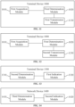
- FIG. 14 is a block diagram of a network device 1400 according to some embodiments of this application.
- the network device includes a third determination module 1410 and a second indication module 1420.
- the third determination module 1410 is configured to determine the channel-occupation spatial information.
- the second indication module 1420 is configured to indicate the channel-occupation spatial information.
- the second indication module 1420 is configured to indicate the channel-occupation spatial information by using the DCI carrying the UL grant.
- the channel-occupation spatial information is indicated by at least one of the following in the DCI carrying the UL grant:
- the second indication module 1420 is configured to indicate the channel-occupation spatial information by using Msg2 in the random access procedure.
- the channel-occupation spatial information is indicated by at least one of the following items in Msg2 in the random access procedure:
- the channel-occupation spatial information includes: channel-sensing spatial information of the terminal device.
- the second indication module 1420 is configured to indicate the channel-occupation spatial information by using a group common PDCCH.
- the second indication module 1420 is configured to indicate the channel-occupation spatial information by using the DCI format 2_0 in the group common PDCCH.
- the channel-occupation spatial information is indicated by using at least one of the following in DCI format 2_0:
- the channel-occupation spatial information includes: channel-sensing spatial information of the network device.
- the channel-occupation spatial information is used for determining the channel-sensing spatial information of the terminal device.
- the channel-sensing spatial information of the terminal device includes: LBT directional information of the terminal device.
- FIG. 15 is a block diagram of a network device 1500 according to some embodiments of this application.
- the network device includes a second acquisition module 1510 and a fourth determination module 1520.
- the second acquisition module 1510 is configured to acquire channel-occupation spatial information.
- the fourth determination module 1520 is configured to determine the channel-sensing spatial information of the network device according to the channel-occupation spatial information.
- the channel-occupation spatial information includes: channel-sensing spatial information of a terminal device or channel-sensing spatial information of the network device.
- the second acquisition module 1510 is configured to acquire the channel-occupation spatial information from the UCI carried in the CG-UL.
- the channel-sensing spatial information of the network device includes: LBT directional information of the network device.
- FIG. 16 is a block diagram of a communication device 1600 according to some embodiments of this application.
- the communication device 1600 shown in FIG. 16 includes a processor 1610, and the processor 1610 is configured to call and run a computer program from a memory to implement the method in some embodiments of this application.
- the communication device 1600 may further include a memory 1620.
- the processor 1610 is configured to call and run the computer program from the memory 1620 to implement the method in some embodiments of this application.
- the memory 1620 may be a separate device independent of the processor 1610, or may be integrated in the processor 1610.
- the communication device 1600 may further include a transceiver 1630, and the processor 1610 is configured to control the transceiver 1630 to communicate with other devices.
- the transceiver 1630 may send information or data to other devices, or receive information or data sent by the other devices.
- the transceiver 1630 may include a transmitter and a receiver.
- the transceiver 1630 may further include an antenna, and the number of antennas may be one or more.
- the communication device 1600 may be the network device in some embodiments of this application, and the communication device 1600 may implement corresponding processes implemented by the network device in each method according to the embodiments of this application. For brevity, details are not repeated herein.
- the communication device 1600 may be the terminal device in some embodiments of this application, and the communication device 1600 may implement corresponding processes implemented by the terminal device in each method according to the embodiments of this application. For brevity, details are not repeated herein.
- FIG. 17 is a block diagram of a chip 1700 according to some embodiments of this application.
- the chip 1700 shown in FIG. 17 includes a processor 1710, and the processor 1710 is configured to call and run a computer program from a memory to implement the method in some embodiments of this application.
- the chip 1700 may further include a memory 1720.
- the processor 1710 is configured to call and run the computer program from the memory 1720 to implement the method in some embodiments of this application.
- the memory 1720 may be a separate device independent of the processor 1710, or may be integrated in the processor 1710.
- the chip 1700 may further include an input interface 1730.
- the processor 1710 is configured to control the input interface 1730 to communicate with other devices or chips, and specifically, may obtain information or data sent by other devices or chips.
- the chip 1700 may further include an output interface 1740.
- the processor 1710 is configured to control the output interface 1740 to communicate with other devices or chips, and specifically, may output information or data to other devices or chips.
- the chip 1700 may be applied to the network device in some embodiments of this application, and the chip may implement the corresponding processes implemented by the network device in the various methods according to the embodiments of this application. For brevity, details are not repeated herein.
- the chip 1700 may be applied to the terminal device in some embodiments of this application, and the chip may implement the corresponding processes implemented by the terminal device in the various methods according to the embodiments of this application. For brevity, details are not repeated herein.
- the chip mentioned in some embodiments of this application may also be referred to as a system-level chip, a system chip, a chip system, a system-on-chip, or the like.
- the processors mentioned above may be general-purpose processors, digital signal processors (DSPs), field programmable gate arrays (FPGAs), application specific integrated circuits (ASICs), or other programmable logic devices, transistor logic devices, discrete hardware components, or the like.
- DSPs digital signal processors
- FPGAs field programmable gate arrays
- ASICs application specific integrated circuits
- the general-purpose processor may be a microprocessor or any conventional processor.
- the memory mentioned above may be volatile memory or non-volatile memory, or may include both volatile memory and non-volatile memory.
- the non-volatile memory may be read-only memory (ROM), programmable ROM (PROM), erasable PROM (EPROM), electrically EPROM (EEPROM) or flash memory.
- ROM read-only memory
- PROM programmable ROM
- EPROM erasable PROM
- EEPROM electrically EPROM
- flash memory may be random access memory (RAM).
- RAM random access memory
- the memories mentioned above are exemplary but not restrictive.
- the memory in some embodiments of this application may also be static RAM (SRAM), dynamic RAM (DRAM), synchronous DRAM (SDRAM), double data rate SDRAM (DDR SDRAM), enhanced SDRAM (ESDRAM), synch link DRAM (SLDRAM), direct rambus RAM (DR RAM), and the like.
- SRAM static RAM
- DRAM dynamic RAM
- SDRAM synchronous DRAM
- DDR SDRAM double data rate SDRAM
- ESDRAM enhanced SDRAM
- SLDRAM synch link DRAM
- DR RAM direct rambus RAM
- FIG. 18 is a block diagram of a communication system 1800 according to some embodiments of this application. As shown in FIG. 18 , the communication system 1800 includes a terminal device 1810 and a network device 1820.
- the terminal device 1810 is configured to acquire the channel-occupation spatial information; and determine, according to the channel-occupation spatial information, the channel-sensing spatial information of the terminal device. Alternatively, the terminal device 1810 is configured to determine the channel-occupation spatial information; and indicate the channel-occupation spatial information.
- the network device 1820 is configured to acquire the channel-occupation spatial information; and determine, according to the channel-occupation spatial information, the channel-sensing spatial information of the network device. Alternatively, the network device 1820 is configured to determine the channel-occupation spatial information; and indicate the channel-occupation spatial information.
- the terminal device 1810 is configured to implement the corresponding functions implemented by the terminal device in the above methods
- the network device 1820 is configured to implement the corresponding functions implemented by the network device in the above methods.
- the terminal device 1810 is configured to implement the corresponding functions implemented by the terminal device in the above methods
- the network device 1820 is configured to implement the corresponding functions implemented by the network device in the above methods.
- Embodiment 1 An information determination method, applied to a terminal device, comprising: acquiring channel-occupation spatial information; and determining, according to the channel-occupation spatial information, channel-sensing spatial information of the terminal device.
- Embodiment 2 The method according to embodiment 1, wherein acquiring the channel-occupation spatial information comprises: acquiring the channel-occupation spatial information from a downlink control signaling (DCI) carrying an uplink (UL) grant.
- DCI downlink control signaling
- UL uplink
- Embodiment 3 The method according to embodiment 2, wherein the channel-occupation spatial information indicated in the DCI carrying the UL grant is indicated by at least one of following: a synchronization signal/physical broadcast channel (SS/PBCH) block index; a non-zero power channel state information reference signal (NZP-CSI-RS) resource identification; a sounding reference signal (SRS) resource identification; a transmission configuration indication (TCI) state; and an SRS resource indicator.
- SS/PBCH synchronization signal/physical broadcast channel
- NZP-CSI-RS non-zero power channel state information reference signal
- SRS sounding reference signal
- TCI transmission configuration indication
- Embodiment 4 The method according to any one of embodiments 1 to 3, further comprising: performing, by the terminal device, a channel sensing according to the channel-sensing spatial information of the terminal device, and when a result of the channel sensing indicates a free channel, using the free channel for uplink transmission.
- Embodiment 5 The method according to any one of embodiments 1 to 4, further comprising: acquiring, by the terminal device, the channel-occupation spatial information in a preset manner.
- Embodiment 6 The method according to embodiment 5, wherein the preset manner comprises at least one of following: acquiring the channel-occupation spatial information from a system information message; acquiring the channel-occupation spatial information from a radio resource control (RRC) message; acquiring the channel-occupation spatial information according to spatial information measured by the terminal device; acquiring the channel-occupation spatial information according to spatial information received through a downlink channel; and acquiring the channel-occupation spatial information from TCI information indicated by a network device in a downlink scheduling.
- RRC radio resource control
- Embodiment 7 The method according to embodiment 1, wherein acquiring the channel-occupation spatial information comprises: acquiring the channel-occupation spatial information from a message Msg2 in a random access procedure.
- Embodiment 8 The method according to embodiment 7, wherein the channel-occupation spatial information indicated by the Msg2 in the random access procedure is indicated by at least one of following: an SS/PBCH block index; an NZP-CSI-RS resource identification; an SRS resource identification; and a TCI state.
- Embodiment 9 The method according to embodiment 1, 7 or 8, further comprising: performing, by the terminal device, a channel sensing according to the channel-sensing spatial information of the terminal device, and when a result of the channel sensing indicates a free channel, using the free channel for transmission of Msg 3 in a random access procedure.
- Embodiment 10 The method according to embodiment 1, 7, 8 or 9, comprising: acquiring, by the terminal device, the channel-occupation spatial information in a preset manner.
- Embodiment 11 The method according to embodiment 10, wherein the preset manner comprises at least one of following: determining the channel-occupation spatial information according to spatial information when sending Msg1 in a random access procedure; and acquiring the channel-occupation spatial information according to spatial information measured by the terminal device.
- Embodiment 12 The method according to any one of embodiments 1 to 11, wherein acquiring the channel-occupation spatial information comprises: acquiring the channel-occupation spatial information from a group common physical downlink control channel (PDCCH).
- PDCH physical downlink control channel
- Embodiment 13 The method according to embodiment 12, wherein acquiring the channel-occupation spatial information from the group common PDCCH comprises: acquiring the channel-occupation spatial information from a DCI format 2_0 in the group common PDCCH.
- Embodiment 14 The method according to embodiment 13, wherein the channel-occupation spatial information indicated in the DCI format 2_0 is indicated by at least one of following: an SS/PBCH block index; an NZP-CSI-RS resource identification; an SRS resource identification; and a TCI state.
- Embodiment 15 The method according to any one of embodiments 12 to 14, comprising: acquiring, by the terminal device, the channel-occupation spatial information in a preset manner.
- Embodiment 16 The method according to embodiment 15, wherein the preset manner comprises: determining the channel-occupation spatial information according to spatial information for receiving the DCI format 2_0.
- Embodiment 17 The method according to any one of embodiments 1 to 16, wherein the channel-occupation spatial information comprises: channel-occupation spatial information of a network device or the channel-sensing spatial information of the terminal device.
- Embodiment 18 The method according to any one of embodiments 1 to 17, wherein the channel-sensing spatial information of the terminal device comprises: listen-before-talk (LBT) directional information of the terminal device.
- LBT listen-before-talk
- Embodiment 19 An information indication method, applied to a terminal device, comprising: determining channel-occupation spatial information; and indicating the channel-occupation spatial information.
- Embodiment 20 The method according to embodiment 19, wherein the channel-occupation spatial information comprises: channel-sensing spatial information of the terminal device or channel-sensing spatial information of a network device.
- Embodiment 21 The method according to embodiment 19 or 20, wherein indicating the channel-occupation spatial information comprises: indicating the channel-occupation spatial information through an uplink control signaling (UCI) carried in a configured grant uplink (CG-UL).
- UCI uplink control signaling
- CG-UL configured grant uplink
- Embodiment 22 The method according to any one of embodiments 19 to 21, wherein the channel-occupation spatial information is used for determining channel-sensing spatial information of a network device.
- Embodiment 23 The method according to embodiment 22, wherein the channel-sensing spatial information of the network device comprises: listen-before-talk (LBT) directional information of the network device.
- LBT listen-before-talk
- Embodiment 24 An information indication method, applied to a network device, comprising: determining channel-occupation spatial information; and indicating the channel-occupation spatial information.
- Embodiment 25 The method according to embodiment 24, wherein indicating the channel-occupation spatial information comprises: indicating the channel-occupation spatial information by using a downlink control signaling (DCI) carrying an uplink (UL) grant.
- DCI downlink control signaling
- Embodiment 26 The method according to embodiment 25, wherein the channel-occupation spatial information is indicated by at least one of following in the DCI carrying the UL grant: a synchronization signal/physical broadcast channel (SS/PBCH) block index; a non-zero power channel state information reference signal (NZP-CSI-RS) resource identification; a sounding reference signal (SRS) resource identification; a transmission configuration indication (TCI) state; and an SRS resource indicator.
- SS/PBCH synchronization signal/physical broadcast channel
- NZP-CSI-RS non-zero power channel state information reference signal
- SRS sounding reference signal
- TCI transmission configuration indication
- Embodiment 27 The method according to embodiment 24, wherein indicating the channel-occupation spatial information comprises: indicating the channel-occupation spatial information by using a message Msg2 in a random access procedure.
- Embodiment 28 The method according to embodiment 27, wherein the channel-occupation spatial information is indicated by at least one of following in the Msg2 in the random access procedure: an SS/PBCH block index; an NZP-CSI-RS resource identification; an SRS resource identification; and a TCI state.
- Embodiment 29 The method according to any one of embodiments 24 to 28, wherein indicating the channel-occupation spatial information comprises: indicating the channel-occupation spatial information by using a group common physical downlink control channel (PDCCH).
- PDCH group common physical downlink control channel
- Embodiment 30 The method according to embodiment 29, wherein indicating the channel-occupation spatial information by using the group common PDCCH comprises: indicating the channel-occupation spatial information by using a DCI format 2_0 in the group common PDCCH.
- Embodiment 31 The method according to embodiment 30, wherein the channel-occupation spatial information is indicated by at least one of following in the DCI format 2_0: an SS/PBCH block index; an NZP-CSI-RS resource identification; an SRS resource identification; and a TCI state.
- Embodiment 32 The method according to any one of embodiments 24 to 31, wherein the channel-occupation spatial information comprises: the channel-occupation spatial information of the network device or channel-sensing spatial information of a terminal device.
- Embodiment 33 The method according to any one of embodiments 24 to 32, wherein the channel-occupation spatial information is used for determining channel-sensing spatial information of a terminal device.
- Embodiment 34 The method according to embodiment 33, wherein the channel-sensing spatial information of the terminal device comprises: listen-before-talk (LBT) directional information of the terminal device.
- LBT listen-before-talk
- Embodiment 35 An information determination method, applied to a network device, comprising: acquiring channel-occupation spatial information; and determining, according to the channel-occupation spatial information, channel-sensing spatial information of the network device.
- Embodiment 36 The method according to embodiment 35, wherein the channel-occupation spatial information comprises: channel-sensing spatial information of a terminal device or the channel-sensing spatial information of the network device.
- Embodiment 37 The method according to embodiment 35 or 36, wherein acquiring the channel-occupation spatial information comprises: acquiring the channel-occupation spatial information from an uplink control signaling (UCI) carried in a configured grant uplink (CG-UL).
- UCI uplink control signaling
- CG-UL configured grant uplink
- Embodiment 38 The method according to any one of embodiments 35 to 37, wherein the channel-sensing spatial information of the network device comprises: listen-before-talk (LBT) directional information of the network device.
- LBT listen-before-talk
- Embodiment 39 A terminal device, comprising: a first acquisition module, configured to acquire channel-occupation spatial information; and a first determination module, configured to determine, according to the channel-occupation spatial information, channel-sensing spatial information of the terminal device.
- Embodiment 40 The terminal device according to embodiment 39, wherein the first acquisition module is configured to: acquire the channel-occupation spatial information from a downlink control signaling (DCI) carrying an uplink (UL) grant.
- DCI downlink control signaling
- UL uplink
- Embodiment 41 The terminal device according to embodiment 39 or 40, further comprising: a first transmission module, configured to perform a channel sensing according to the channel-sensing spatial information of the terminal device, and when a result of the channel sensing indicates a free channel, using the free channel for uplink transmission.
- a first transmission module configured to perform a channel sensing according to the channel-sensing spatial information of the terminal device, and when a result of the channel sensing indicates a free channel, using the free channel for uplink transmission.
- Embodiment 42 The terminal device according to embodiment 39, wherein the first acquisition module is configured to: acquire the channel-occupation spatial information from a message Msg2 in a random access procedure.
- Embodiment 43 The terminal device according to embodiment 42, further comprising: a second transmission module, configured to perform a channel sensing according to the channel-sensing spatial information of the terminal device, and when a result of the channel sensing indicates a free channel, using the free channel for transmission of Msg 3 in a random access procedure.
- a second transmission module configured to perform a channel sensing according to the channel-sensing spatial information of the terminal device, and when a result of the channel sensing indicates a free channel, using the free channel for transmission of Msg 3 in a random access procedure.
- Embodiment 44 The terminal device according to any one of embodiments 39 to 43, wherein the first acquisition module is configured to: acquire the channel-occupation spatial information from a group common physical downlink control channel (PDCCH).
- PDCH physical downlink control channel
- Embodiment 45 The terminal device according to any one of embodiments 39 to 44, wherein the channel-occupation spatial information comprises: channel-occupation spatial information of a network device or the channel-sensing spatial information of the terminal device.
- Embodiment 46 The terminal device according to any one of embodiments 39 to 45, wherein the channel-sensing spatial information of the terminal device comprises: listen-before-talk (LBT) directional information of the terminal device.
- LBT listen-before-talk
- Embodiment 47 A terminal device, comprising: a second determination module, configured to determine channel-occupation spatial information; and a first indication module, configured to indicate the channel-occupation spatial information.
- Embodiment 48 The terminal device according to embodiment 47, wherein the channel-occupation spatial information comprises: channel-sensing spatial information of the terminal device or channel-sensing spatial information of a network device.
- Embodiment 49 The terminal device according to embodiment 47 or 48, wherein the first indication module is configured to indicate the channel-occupation spatial information through an uplink control signaling (UCI) carried in a configured grant uplink (CG-UL).
- UCI uplink control signaling
- CG-UL configured grant uplink
- Embodiment 50 The terminal device according to any one of embodiments 47 to 49, wherein the channel-occupation spatial information is used for determining channel-sensing spatial information of a network device.
- Embodiment 51 The terminal device according to embodiment 50, wherein the channel-sensing spatial information of the network device comprises: listen-before-talk (LBT) directional information of the network device.
- LBT listen-before-talk
- Embodiment 52 A network device, comprising: a third determination module, configured to determine channel-occupation spatial information; and a second indication module, configured to indicate the channel-occupation spatial information.
- Embodiment 53 The network device according to embodiment 52, wherein the second indication module is configured to: indicate the channel-occupation spatial information by using a downlink control signaling (DCI) carrying an uplink (UL) grant.
- DCI downlink control signaling
- Embodiment 54 The network device according to embodiment 52, wherein the second indication module is configured to: indicate the channel-occupation spatial information by using a message Msg2 in a random access procedure.
- Embodiment 55 The network device according to any one of embodiments 52 to 54, wherein the second indication module is configured to: indicate the channel-occupation spatial information by using a group common physical downlink control channel (PDCCH).
- PDCH group common physical downlink control channel
- Embodiment 56 The network device according to any one of embodiments 52 to 55, wherein the channel-occupation spatial information comprises: the channel-occupation spatial information of the network device or channel-sensing spatial information of a terminal device.
- Embodiment 57 The network device according to any one of embodiments 52 to 56, wherein the channel-occupation spatial information is used for determining channel-sensing spatial information of a terminal device.
- Embodiment 58 The network device according to embodiment 57, wherein the channel-sensing spatial information of the terminal device comprises: listen-before-talk (LBT) directional information of the terminal device.
- LBT listen-before-talk
- Embodiment 59 A network device, comprising: a second acquisition module, configured to acquire channel-occupation spatial information; and a fourth determination module, configured to determine, according to the channel-occupation spatial information, channel-sensing spatial information of the network device.
- Embodiment 60 The network device according to embodiment 59, wherein the channel-occupation spatial information comprises: channel-sensing spatial information of a terminal device or the channel-sensing spatial information of the network device.
- Embodiment 61 The network device according to embodiment 59 or 60, wherein the second acquisition module is configured to acquire the channel-occupation spatial information from an uplink control signaling (UCI) carried in a configured grant uplink (CG-UL).
- UCI uplink control signaling
- CG-UL configured grant uplink
- Embodiment 62 The network device according to any one of embodiments 59 to 61, wherein the channel-sensing spatial information of the network device comprises: listen-before-talk (LBT) directional information of the network device.
- LBT listen-before-talk
- Embodiment 63 A terminal device, comprising a processor and a memory, wherein the memory is configured to store a computer program, and the processor is configured to, through invoking and running the computer program stored in the memory, implement the method according to any one of embodiments 1-18.
- Embodiment 64 A terminal device, comprising a processor and a memory, wherein the memory is configured to store a computer program, and the processor is configured to, through invoking and running the computer program stored in the memory, implement the method according to any one of embodiments 19-23.
- Embodiment 65 A network device, comprising a processor and a memory, wherein the memory is configured to store a computer program, and the processor is configured to, through invoking and running the computer program stored in the memory, implement the method according to any one of embodiments 24-34.
- Embodiment 66 A network device, comprising a processor and a memory, wherein the memory is configured to store a computer program, and the processor is configured to, through invoking and running the computer program stored in the memory, implement the method according to any one of embodiments 35-38.
- Embodiment 67 A chip, comprising a processor, wherein the processor is configured to invoke and run a computer program stored in a memory, causing a device installed with the chip to implement the method according to any one of embodiments 1-18.
- Embodiment 68 A chip, comprising a processor, wherein the processor is configured to invoke and run a computer program stored in a memory, causing a device installed with the chip to implement the method according to any one of embodiments 19-23.
- Embodiment 69 A chip, comprising a processor, wherein the processor is configured to invoke and run a computer program stored in a memory, causing a device installed with the chip to implement the method according to any one of embodiments 24-34.
- Embodiment 70 A chip, comprising a processor, wherein the processor is configured to invoke and run a computer program stored in a memory, causing a device installed with the chip to implement the method according to any one of embodiments 35-38.
- Embodiment 71 A computer-readable storage medium, storing a computer program thereon, wherein the computer program is used for causing a computer to implement the method according to any one of embodiments 1-18.
- Embodiment 72 A computer-readable storage medium, storing a computer program thereon, wherein the computer program is used for causing a computer to implement the method according to any one of embodiments 19-23.
- Embodiment 73 A computer-readable storage medium, storing a computer program thereon, wherein the computer program is used for causing a computer to implement the method according to any one of embodiments 24-34.
- Embodiment 74 A computer-readable storage medium, storing a computer program thereon, wherein the computer program is used for causing a computer to implement the method according to any one of embodiments 35-38.
- Embodiment 75 A computer program product, comprising computer program instructions, wherein the computer program instructions are used for causing a computer to implement the method according to any one of embodiments 1-18.
- Embodiment 76 A computer program product, comprising computer program instructions, wherein the computer program instructions are used for causing a computer to implement the method according to any one of embodiments 19-23.
- Embodiment 77 A computer program product, comprising computer program instructions, wherein the computer program instructions are used for causing a computer to implement the method according to any one of embodiments 24-34.
- Embodiment 78 A computer program product, comprising computer program instructions, wherein the computer program instructions are used for causing a computer to implement the method according to any one of embodiments 35-38.
- Embodiment 79 A computer program, wherein the computer program is used for causing a computer to implement the method according to any one of embodiments 1-18.
- Embodiment 80 A computer program, wherein the computer program is used for causing a computer to implement the method according to any one of embodiments 19-23.
- Embodiment 81 A computer program, wherein the computer program is used for causing a computer to implement the method according to any one of embodiments 24-34.
- Embodiment 82 A computer program, wherein the computer program is used for causing a computer to implement the method according to any one of embodiments 35-38.
- the above embodiments may be implemented in whole or in part by software, hardware, firmware, or any combination thereof.
- software When implemented by software, they may be implemented in the form of a computer program product in whole or in part.
- the computer program product includes one or more computer instructions.
- the computer may be a general-purpose computer, a special-purpose computer, a computer network, or other programmable devices.
- the computer instructions may be stored in a computer-readable storage medium, or transmitted from one computer-readable storage medium to another computer-readable storage medium.
- the computer instructions may be transmitted from a website, computer, server, or data center through a cable (e.g., coaxial cable, optical fiber, digital subscriber line (DSL)) or a wireless manner (e.g., infrared, radio, microwave, and the like) to another website, computer, server or data center.
- the computer-readable storage medium may be any available medium that can be accessed by a computer or a data storage device such as a server or data center integrated with one or more available mediums.
- the available medium may be a magnetic medium (e.g., a floppy disk, a hard disk, and a magnetic tape), an optical medium (e.g., a DVD), or a semiconductor medium (e.g., a solid state disk (SSD)).
- SSD solid state disk
- the size of the sequence number of the above-mentioned processes does not mean the order of execution, and the execution order of each process should be determined by its function and internal logic, and should not constitute any limitation to the embodiments of this application.
Landscapes
- Engineering & Computer Science (AREA)
- Signal Processing (AREA)
- Computer Networks & Wireless Communication (AREA)
- Quality & Reliability (AREA)
- Computer Security & Cryptography (AREA)
- Mobile Radio Communication Systems (AREA)
- Communication Control (AREA)
Priority Applications (1)
| Application Number | Priority Date | Filing Date | Title |
|---|---|---|---|
| EP25155780.7A EP4531477A3 (de) | 2020-01-09 | 2020-01-09 | Informationsbestimmungsverfahren, informationsanzeigeverfahren, endgerätevorrichtung und netzwerkvorrichtung |
Applications Claiming Priority (3)
| Application Number | Priority Date | Filing Date | Title |
|---|---|---|---|
| PCT/CN2020/071122 WO2021138866A1 (zh) | 2020-01-09 | 2020-01-09 | 信息确定方法、信息指示方法、终端设备和网络设备 |
| EP25155780.7A EP4531477A3 (de) | 2020-01-09 | 2020-01-09 | Informationsbestimmungsverfahren, informationsanzeigeverfahren, endgerätevorrichtung und netzwerkvorrichtung |
| EP20912787.7A EP4080962B1 (de) | 2020-01-09 | 2020-01-09 | Informationsbestimmungsverfahren, informationsanzeigeverfahren, endgerät und netzwerkvorrichtung |
Related Parent Applications (2)
| Application Number | Title | Priority Date | Filing Date |
|---|---|---|---|
| EP20912787.7A Division-Into EP4080962B1 (de) | 2020-01-09 | 2020-01-09 | Informationsbestimmungsverfahren, informationsanzeigeverfahren, endgerät und netzwerkvorrichtung |
| EP20912787.7A Division EP4080962B1 (de) | 2020-01-09 | 2020-01-09 | Informationsbestimmungsverfahren, informationsanzeigeverfahren, endgerät und netzwerkvorrichtung |
Publications (2)
| Publication Number | Publication Date |
|---|---|
| EP4531477A2 true EP4531477A2 (de) | 2025-04-02 |
| EP4531477A3 EP4531477A3 (de) | 2025-04-09 |
Family
ID=76787403
Family Applications (2)
| Application Number | Title | Priority Date | Filing Date |
|---|---|---|---|
| EP20912787.7A Active EP4080962B1 (de) | 2020-01-09 | 2020-01-09 | Informationsbestimmungsverfahren, informationsanzeigeverfahren, endgerät und netzwerkvorrichtung |
| EP25155780.7A Pending EP4531477A3 (de) | 2020-01-09 | 2020-01-09 | Informationsbestimmungsverfahren, informationsanzeigeverfahren, endgerätevorrichtung und netzwerkvorrichtung |
Family Applications Before (1)
| Application Number | Title | Priority Date | Filing Date |
|---|---|---|---|
| EP20912787.7A Active EP4080962B1 (de) | 2020-01-09 | 2020-01-09 | Informationsbestimmungsverfahren, informationsanzeigeverfahren, endgerät und netzwerkvorrichtung |
Country Status (6)
| Country | Link |
|---|---|
| US (1) | US20220338262A1 (de) |
| EP (2) | EP4080962B1 (de) |
| KR (1) | KR20220124215A (de) |
| CN (2) | CN114845417B (de) |
| ES (1) | ES3029283T3 (de) |
| WO (1) | WO2021138866A1 (de) |
Families Citing this family (4)
| Publication number | Priority date | Publication date | Assignee | Title |
|---|---|---|---|---|
| US11917588B2 (en) * | 2020-03-31 | 2024-02-27 | Qualcomm Incorporated | Configured communications techniques in shared radio frequency spectrum based on channel occupancy time |
| US12224830B2 (en) * | 2020-04-08 | 2025-02-11 | Apple Inc. | Channel state information feedback in wireless communications |
| WO2022188097A1 (en) * | 2021-03-11 | 2022-09-15 | Lenovo (Beijing) Limited | Method and apparatus for monitoring downlink control information |
| CN117336872A (zh) * | 2022-06-22 | 2024-01-02 | 维沃移动通信有限公司 | 共享信道的方法、设备及可读存储介质 |
Family Cites Families (14)
| Publication number | Priority date | Publication date | Assignee | Title |
|---|---|---|---|---|
| CN105101300A (zh) * | 2014-05-09 | 2015-11-25 | 中兴通讯股份有限公司 | 基于竞争的资源选择方法及装置 |
| TWI767306B (zh) * | 2015-11-10 | 2022-06-11 | 美商Idac控股公司 | 波束成形系統下行控制頻道設計及傳訊 |
| CN106851839B (zh) * | 2017-03-14 | 2020-06-12 | 北京佰才邦技术有限公司 | 帧结构确定方法和基站 |
| CN110049559B (zh) * | 2018-01-17 | 2021-11-12 | 维沃移动通信有限公司 | 侦听指示方法、终端及网络设备 |
| US11051353B2 (en) * | 2018-03-19 | 2021-06-29 | Apple Inc. | PUCCH and PUSCH default beam considering beam failure recovery |
| CN110351881B (zh) * | 2018-04-04 | 2021-11-19 | 展讯通信(上海)有限公司 | 信道接入方法及装置、存储介质、终端、基站 |
| CN110366248B (zh) * | 2018-04-04 | 2024-04-30 | 中兴通讯股份有限公司 | 上行传输、通信方法、装置及基站、终端、存储介质 |
| WO2019193422A2 (en) * | 2018-04-06 | 2019-10-10 | Lenovo (Singapore) Pte. Ltd. | Configuring for bandwidth parts |
| CN110505026B (zh) * | 2018-05-18 | 2022-03-29 | 华为技术有限公司 | 信号侦听的方法、相关设备及系统 |
| US11140711B2 (en) * | 2018-08-08 | 2021-10-05 | Acer Incorporated | Method for downlink reception and user equipment using the same |
| CN110417525B (zh) * | 2018-09-28 | 2021-05-04 | 华为技术有限公司 | 一种通信方法、装置、处理装置及存储介质 |
| CN111343718B (zh) * | 2018-12-18 | 2022-09-09 | 北京紫光展锐通信技术有限公司 | 占有时隙的确定方法及装置、存储介质、用户终端 |
| CN110040550B (zh) * | 2019-04-22 | 2020-06-12 | 四川华净净化设备科技有限公司 | 用于彩钢夹芯板制造机的限位导向装置 |
| CN110536453B (zh) * | 2019-09-16 | 2023-09-26 | 中兴通讯股份有限公司 | 数据传输方法、装置和系统 |
-
2020
- 2020-01-09 WO PCT/CN2020/071122 patent/WO2021138866A1/zh not_active Ceased
- 2020-01-09 ES ES20912787T patent/ES3029283T3/es active Active
- 2020-01-09 CN CN202210551945.7A patent/CN114845417B/zh active Active
- 2020-01-09 CN CN202080076210.2A patent/CN114642057A/zh active Pending
- 2020-01-09 KR KR1020227026824A patent/KR20220124215A/ko not_active Ceased
- 2020-01-09 EP EP20912787.7A patent/EP4080962B1/de active Active
- 2020-01-09 EP EP25155780.7A patent/EP4531477A3/de active Pending
-
2022
- 2022-07-06 US US17/858,654 patent/US20220338262A1/en active Pending
Also Published As
| Publication number | Publication date |
|---|---|
| KR20220124215A (ko) | 2022-09-13 |
| ES3029283T3 (en) | 2025-06-23 |
| EP4080962B1 (de) | 2025-04-16 |
| CN114642057A (zh) | 2022-06-17 |
| EP4080962A1 (de) | 2022-10-26 |
| EP4531477A3 (de) | 2025-04-09 |
| CN114845417B (zh) | 2024-11-05 |
| WO2021138866A1 (zh) | 2021-07-15 |
| CN114845417A (zh) | 2022-08-02 |
| US20220338262A1 (en) | 2022-10-20 |
| EP4080962A4 (de) | 2022-12-14 |
Similar Documents
| Publication | Publication Date | Title |
|---|---|---|
| US12519535B2 (en) | Antenna switching method, terminal device and communication device | |
| US20220338262A1 (en) | Information determination method, information indication method, terminal device, and network device | |
| WO2021163937A1 (zh) | 天线切换能力指示方法、终端设备及通信设备 | |
| CN111757542B (zh) | 信号传输的方法和设备 | |
| US11463194B2 (en) | Information determination method, terminal apparatus, and network apparatus | |
| US20210007069A1 (en) | Signal transmission method, network device, and terminal device | |
| CN113169848A (zh) | 无线通信方法、终端设备和网络设备 | |
| US11546044B2 (en) | Wireless communication method, terminal device and network device | |
| US20230069646A1 (en) | Method for determining transmission resources and terminal device | |
| CN115699894A (zh) | 无线通信方法、终端设备和网络设备 | |
| EP4109938B1 (de) | Verfahren zum senden von sidelink-kapazität und endgerätevorrichtung | |
| CN113574944A (zh) | 无线通信方法、网络设备和终端设备 | |
| US11792831B2 (en) | Method and device for signal transmission | |
| EP4096323A1 (de) | Drahtloskommunikationsverfahren und -vorrichtung | |
| US12490206B2 (en) | Signal detection method, signal transmission method, terminal device, and network device | |
| WO2019242681A1 (zh) | 无线链路监测的方法和终端设备 | |
| CN117397331A (zh) | 无线通信的方法和终端设备 |
Legal Events
| Date | Code | Title | Description |
|---|---|---|---|
| PUAI | Public reference made under article 153(3) epc to a published international application that has entered the european phase |
Free format text: ORIGINAL CODE: 0009012 |
|
| STAA | Information on the status of an ep patent application or granted ep patent |
Free format text: STATUS: THE APPLICATION HAS BEEN PUBLISHED |
|
| PUAL | Search report despatched |
Free format text: ORIGINAL CODE: 0009013 |
|
| AC | Divisional application: reference to earlier application |
Ref document number: 4080962 Country of ref document: EP Kind code of ref document: P |
|
| AK | Designated contracting states |
Kind code of ref document: A2 Designated state(s): AL AT BE BG CH CY CZ DE DK EE ES FI FR GB GR HR HU IE IS IT LI LT LU LV MC MK MT NL NO PL PT RO RS SE SI SK SM TR |
|
| AK | Designated contracting states |
Kind code of ref document: A3 Designated state(s): AL AT BE BG CH CY CZ DE DK EE ES FI FR GB GR HR HU IE IS IT LI LT LU LV MC MK MT NL NO PL PT RO RS SE SI SK SM TR |
|
| RIC1 | Information provided on ipc code assigned before grant |
Ipc: H04W 72/04 20230101AFI20250304BHEP |
|
| STAA | Information on the status of an ep patent application or granted ep patent |
Free format text: STATUS: REQUEST FOR EXAMINATION WAS MADE |
|
| 17P | Request for examination filed |
Effective date: 20250929 |