EP4531424A1 - Thin panel surface mount microphone - Google Patents
Thin panel surface mount microphone Download PDFInfo
- Publication number
- EP4531424A1 EP4531424A1 EP24199503.4A EP24199503A EP4531424A1 EP 4531424 A1 EP4531424 A1 EP 4531424A1 EP 24199503 A EP24199503 A EP 24199503A EP 4531424 A1 EP4531424 A1 EP 4531424A1
- Authority
- EP
- European Patent Office
- Prior art keywords
- adhesive member
- pcba
- structure panel
- housing
- sensor
- Prior art date
- Legal status (The legal status is an assumption and is not a legal conclusion. Google has not performed a legal analysis and makes no representation as to the accuracy of the status listed.)
- Pending
Links
Images

Classifications
-
- H—ELECTRICITY
- H04—ELECTRIC COMMUNICATION TECHNIQUE
- H04R—LOUDSPEAKERS, MICROPHONES, GRAMOPHONE PICK-UPS OR LIKE ACOUSTIC ELECTROMECHANICAL TRANSDUCERS; ELECTRIC HEARING AIDS; PUBLIC ADDRESS SYSTEMS
- H04R1/00—Details of transducers, loudspeakers or microphones
- H04R1/08—Mouthpieces; Microphones; Attachments therefor
- H04R1/083—Special constructions of mouthpieces
-
- H—ELECTRICITY
- H04—ELECTRIC COMMUNICATION TECHNIQUE
- H04R—LOUDSPEAKERS, MICROPHONES, GRAMOPHONE PICK-UPS OR LIKE ACOUSTIC ELECTROMECHANICAL TRANSDUCERS; ELECTRIC HEARING AIDS; PUBLIC ADDRESS SYSTEMS
- H04R1/00—Details of transducers, loudspeakers or microphones
- H04R1/08—Mouthpieces; Microphones; Attachments therefor
- H04R1/083—Special constructions of mouthpieces
- H04R1/086—Protective screens, e.g. all weather or wind screens
-
- H—ELECTRICITY
- H04—ELECTRIC COMMUNICATION TECHNIQUE
- H04R—LOUDSPEAKERS, MICROPHONES, GRAMOPHONE PICK-UPS OR LIKE ACOUSTIC ELECTROMECHANICAL TRANSDUCERS; ELECTRIC HEARING AIDS; PUBLIC ADDRESS SYSTEMS
- H04R1/00—Details of transducers, loudspeakers or microphones
- H04R1/20—Arrangements for obtaining desired frequency or directional characteristics
- H04R1/22—Arrangements for obtaining desired frequency or directional characteristics for obtaining desired frequency characteristic only
- H04R1/222—Arrangements for obtaining desired frequency or directional characteristics for obtaining desired frequency characteristic only for microphones
-
- H—ELECTRICITY
- H04—ELECTRIC COMMUNICATION TECHNIQUE
- H04R—LOUDSPEAKERS, MICROPHONES, GRAMOPHONE PICK-UPS OR LIKE ACOUSTIC ELECTROMECHANICAL TRANSDUCERS; ELECTRIC HEARING AIDS; PUBLIC ADDRESS SYSTEMS
- H04R2201/00—Details of transducers, loudspeakers or microphones covered by H04R1/00 but not provided for in any of its subgroups
- H04R2201/02—Details casings, cabinets or mounting therein for transducers covered by H04R1/02 but not provided for in any of its subgroups
- H04R2201/021—Transducers or their casings adapted for mounting in or to a wall or ceiling
-
- H—ELECTRICITY
- H04—ELECTRIC COMMUNICATION TECHNIQUE
- H04R—LOUDSPEAKERS, MICROPHONES, GRAMOPHONE PICK-UPS OR LIKE ACOUSTIC ELECTROMECHANICAL TRANSDUCERS; ELECTRIC HEARING AIDS; PUBLIC ADDRESS SYSTEMS
- H04R2231/00—Details of apparatus or processes specially adapted for the manufacture of transducers or diaphragms therefor covered by H04R31/00, not provided for in its subgroups
- H04R2231/003—Manufacturing aspects of the outer suspension of loudspeaker or microphone diaphragms or of their connecting aspects to said diaphragms
-
- H—ELECTRICITY
- H04—ELECTRIC COMMUNICATION TECHNIQUE
- H04R—LOUDSPEAKERS, MICROPHONES, GRAMOPHONE PICK-UPS OR LIKE ACOUSTIC ELECTROMECHANICAL TRANSDUCERS; ELECTRIC HEARING AIDS; PUBLIC ADDRESS SYSTEMS
- H04R2499/00—Aspects covered by H04R or H04S not otherwise provided for in their subgroups
- H04R2499/10—General applications
- H04R2499/13—Acoustic transducers and sound field adaptation in vehicles
Definitions
- the present disclosure relates to a sound sensing device and more particularly, to a surface-mounted and environmentally sealed sound sensing device.
- a microphone element To achieve good acoustic performance, such as high sensitivity and wide bandwidth, a microphone element, by design, requires a port hole to provide a direct air path between the sensing element and the external environment. This makes the microphone element susceptible to damage caused by harsh environmental conditions or foreign contaminants.
- acoustic mesh or acoustic membrane in front of the port hole of a microphone element.
- the acoustic mesh or membrane is often made from materials (or structures) that have very small pore sizes, or micropores, that are typically several to several hundred micrometers in diameter.
- the micropores are big enough to allow air molecules to pass through yet are small enough to block dust particles. It is also difficult for liquid molecules to pass through due to the large surface tension formed among liquid molecules, thus making it waterproof. Therefore, the acoustic mesh or acoustic membrane forms a physical layer to isolate and protect the delicate sensing element from the external environment.
- acoustic mesh or membrane materials are PTFE (polytetrafluoroethylene) and PDMS (polydimethylsiloxane).
- acoustic mesh and acoustic membrane may be used interchangeably, the subtle difference between them is that mesh often refers to materials (or structures) with larger pore sizes whereas membrane often refers to materials (or structures) with smaller pore sizes.
- mesh often refers to materials (or structures) with larger pore sizes
- membrane often refers to materials (or structures) with smaller pore sizes.
- an acoustic mesh or membrane needs to be thin, flexible, and low in mass, which could make it easily damaged by sharp objects (e.g., road debris).
- sharp objects e.g., road debris
- liquids like water may penetrate through the pores, making it impossible to meet the IPx9K rating under high pressure high temperature spray.
- Another approach to address the problem is to attach an accelerometer to a structure surface (e.g., glass window or door panel of a vehicle) to measure the sound induced vibration of the panel that correlates with and represents the sound in the environment. Since, by design, accelerometers are entirely sealed to the environment, this approach solves the weatherproof problem perfectly.
- An example of such an accelerometer-based sound sensing solution using piezo-diaphragms can be found in a recent US patent No. 11,533,568B1 .
- piezo diaphragms are typically much larger in size than a microphone element (e.g., a MEMS or ECM microphone element) making it more difficult to integrate them into a protective housing while achieving good electromagnetic interference and electromagnetic compatibility (EMI/EMC) performance.
- a microphone element e.g., a MEMS or ECM microphone element
- a sound and vibration sensor having a housing, a PCBA attached to a perimeter edge inside the housing, an adhesive member sealed to both a perimeter edge of one end of the housing and a structure panel defining a sealed cavity wherein a microphone element senses a change in acoustic pressure inside the sealed cavity caused by sound waves striking the structure panel.
- a leak channel in the PCBA creates a ventilation path between the sealed cavity and a cavity inside the housing.
- the structure panel is thinned in an area that receives the adhesive member.
- the thinned area may be configured to match an outer perimeter of the adhesive member.
- the structure panel is a vehicle body panel.
- the adhesive member may adhere to a B-side of the vehicle body panel.
- the PCBA is flush-mounted at one end of the housing and a thickness of the adhesive member defines a small gap distance.
- the sound and vibration sensor has a vent in the cavity inside the housing to balance static air pressure.
- the vent is covered with a dense mesh layer.
- FIG. 1A is a cut away view of a sound sensing device 100 according to one or more embodiments.
- a printed circuit board assembly (PCBA) 102 is flush mounted inside a housing 104 at one end of the housing 104 so that a water-tight seal is created between the housing 104 and a perimeter edge 106 of the PCBA 102.
- PCBA printed circuit board assembly
- the PCBA 102 is a printed circuit board (PCB) 108 having a port hole, or an aperture, 110 and includes any components needed for the sound sensing device 100 to operate.
- Other circuit components may include, but are not limited to, a preamplifier, an analog-to-digital converter, a microphone element 112, and any other components necessary for the sound sensing device to operate.
- the microphone element 112 has an acoustic port 114 and is mounted on the PCB 108 so that the acoustic port 114 is aligned with the port hole 110 on the PCB 108 to allow sound waves external to the sound sensing device 100 to reach a first diaphragm (not shown) that is exposed via the acoustic port 114 of the microphone element 112.
- the microphone element 112 may be a micro-electro-mechanical system (MEMS) device. In one or more embodiments, the microphone element 112 may be an electret condenser microphone (ECM) device. In one or more embodiments, the sound sensing device 100 may include an adhesive member 116 shaped in a manner that matches an outer perimeter of the housing 104. In one or more embodiments, the adhesive member 116 is shaped as a ring, for example, as in the case of a circular housing 104.
- FIG. 1B is a cut away view of the sound sensing device 100 mounted to a structure panel 120.
- the adhesive member 116 aligns with and attaches to a bottom perimeter 118 of the housing 104 while also attaching to and creating a seal with the structure panel 120, for example, a vehicle body panel.
- the adhesive member 116 should be strong and durable for typical automotive applications and should be able to withstand extreme temperatures and humidity. Additionally, or alternatively, the adhesive member 116 may be conformable, for example, having a foam core, to ensure good contact, thus good seal, is achieved between surfaces that may be even just slightly mismatched.
- the sealed cavity 122 defines a first sealed volume, V1, based on the thickness, h, of the adhesive member 116 and the dimensions of the housing 104.
- Displacement of the structure panel 120 dynamically changes the first sealed volume, V1, generating acoustic pressure that is proportional to the volume change inside the sealed cavity 122 that is sensed by the microphone element 112.
- the structure panel 120 behaves as a second diaphragm for sound sensing.
- a first diaphragm (not shown) is inside the microphone element 112.
- the sound sensing device 100 uses the structure panel 120 to seal the cavity 122 and provide environmental protection for the microphone element 112 of the sound sensing device 100.
- a vehicle body panel made of sheet metal (e.g., steel or aluminum alloy) or plastic is undoubtably strong enough to meet the IP6K9K protection rating.
- Sensitivity, frequency response characteristics, and bandwidth of the sound sensing device 100 may be determined by the volume, V1, of the sealed cavity 122, an area of the structure panel 120 that is enclosed by the adhesive member 116, a material property of the structure panel 120, and a thickness of the adhesive member 116.
- a smaller sealed cavity, 122, or first sealed volume, V1 is preferred. This requires a small gap distance 128 between the structure panel 120 and the bottom surface 124 of the PCBA 102.
- a thicker adhesive member 116 will create a larger sealed cavity 122 and a thinner adhesive member will create a smaller sealed cavity 122.
- an enclosed area equivalent to a circular area of a diameter between 10 mm and 80 mm may be preferred.
- a total volume of the sealed cavity 122 may be kept below 350 mm 3 .
- the gap distance, 128, mostly controlled by the thickness of the adhesive member 116, may be preferably between 0.1 and 0.5 mm.
- automotive body panels are typically 0.5 mm to 2 mm thick depending on the type of material (e.g., steel panel is thinner). This thickness range, combined with the preferred ranges of the enclosed area, the gap distance 128, and the sealed cavity 122 volume, V1, is suitable to generate sufficient acoustic pressure in the small, sealed cavity 122 under the excitation of typical external sound pressure levels in the environment (e.g., on the order of 50 - 120 dB sound pressure level (SPL)).
- SPL sound pressure level
- FIG. 2 shows a vehicle 200 exemplary locations 202a-202n for mounting the sound sensing device on the vehicle 200. More than one sound sensing device may be positioned on the vehicle, and the locations may be selected depending upon the sounds being targeted for detection. For example, but not limited to the sound sensing device being surface-mounted for external or internal voice detection to transmit signals indicative of voice commands to one or more controllers 204 on the vehicle.
- the one or more controllers 204 may be responsible for activating or deactivating a vehicle operation (e.g., open/close a trunk, door, liftgate, etc.).
- the sound sensing device may be used in connection with detecting background noise signals that may be used by one or more controllers 204 in an active noise cancellation (ANC) and/or road noise cancellation (RNC) system.
- the microphone element (not shown in FIG. 2 ) may include an analog, or a digital, interface, such as A2B, to communicate with the one or more controllers 204 on the vehicle 200.
- the sound sensing device may be mounted on any thin structure panel of the vehicle 200 such as a door panel, a roof panel, a front/rear bumper panel, etc. Additionally, or alternatively, the sound sensing device may be mounted to an inner facing side, B-side, of the structure panel to entirely hide the device from view.
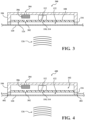
- FIG. 3 is a cutaway view of one or more embodiments of the sound sensing device 300 having a leak channel 302 in the PCBA 102 and a vent 304 in the housing 104.
- the leak channel 302 and the vent 304 define a ventilation path connecting the cavity 122 to the external environment wherein the ventilation path balances static air pressure between the cavity 122 and the external environment.
- a cross-sectional area of the leak channel 302 should be kept as small as possible.
- the vent 304 in the housing may have a circular (or equivalent) area with a diameter smaller than 1 mm.
- a dense mesh layer 306 may be positioned inside the housing 104 to cover the vent 304.
- the dense mesh layer 306 may have even smaller pore sizes than an air breathable acoustic mesh to not only prevent foreign objects, water, and moisture from entering the housing, and ultimately the microphone element 112 but also present high resistance for air molecules to pass through. Yet the dense mesh layer 306 still allows static pressure equalization when a difference between the internal and external static air pressure becomes large.
- An exemplary dense mesh layer 306 may be made of expanded polytetrafluororethylene (ePTFE) material with a thickness in a range of 0.1 to 0.5 mm.
- ePTFE expanded polytetrafluororethylene
- FIG. 4 is a cutaway view of one or more embodiments of a sound sensing device 400 that has a shape that matches a pre-molded, or built-in, recessed area 402 on the structure panel 120.
- An advantage is that the recessed area 402 of the structure panel that receives the adhesive member 116 of the sound sensing device is thinner than the surrounding body panel thereby increasing a sensitivity and a signal-to-noise ratio (SNR) of the sound sensing device 400.
- SNR signal-to-noise ratio
- the recessed area 402 also helps to ensure that the sound sensing device 400 is positioned and mounted to the proper location on the vehicle body during assembly.
- the sound sensing device 100, 300, 400 of the inventive subject matter attaches onto a structure panel 120 such as a vehicle body panel, providing an environmentally sealed surface mounted microphone suitable for external microphone applications. Attaching the sound sensing device to the structure panel in a fully sealed manner not only environmentally protects the microphone element, but the structure panel 120, 420 acts as a second diaphragm for the microphone element 112.
- An advantage over traditional microphones for use on an exterior of an automotive vehicle is that the sound sensing device 100, 300, 400 has a fully sealed attachment to the structure panel ensuring that the sound sensing device 100, 300, 400 will be able to meet the highest ingress protection rating (e.g., IP6K9K).
- the sound sensing device 100, 300, 400 presents over traditional microphones is that the sound sensing device 100, 300, 400 is integrated into vehicle structures, by way of the adhesive member, allowing it to be used externally, yet remaining totally hidden, for aesthetic reasons.
- the sound sensing device 100, 300, 400 is much smaller in size, in thickness and in height than the piezo-diaphragm.
- the device 100, 300, 400 may be integrated into a much smaller module housing 104 and provide improved EMI/EMC performance.
- a sound and vibration sensor comprises a housing, a printed circuit board assembly (PCBA) including a microphone element, the PCBA being attached to a perimeter edge within the housing, and an adhesive member having a first side adhered, in a sealed manner, to a perimeter edge of one end of the housing, the adhesive member having a second side adhered, in a sealed manner, to a structure panel, and a sealed cavity defined between the structure panel and an area below the PCBA.
- the microphone element senses a change in acoustic pressure inside the sealed cavity caused by sound waves striking the structure panel.
- the sensor may further comprise a ventilation path created by a leak channel in the PCBA between the sealed cavity below the PCBA and an area of the housing above the printed circuit board assembly and a vent in the housing above the PCBA.
- the leak channel may further comprise a circular cross-sectional area less than 0.4 mm in diameter and the vent further comprises a circular cross-sectional area less than 1.0 mm.
- the sensor may further comprise a dense mesh layer covering the vent.
- a portion of the structure panel that receives the second side of the adhesive member may be thinned in comparison to surrounding structure panel.
- an outer perimeter of the thinned structure panel may be configured to match an outer perimeter of the adhesive member to receive the adhesive member in a fully sealed manner.
- the adhesive member may have a conformable foam core.
- the structure panel may be a vehicle body panel. It is possible, according to some examples, that the second side of the adhesive member is adhered to a B-side of the vehicle body panel.
- a surface-mounted microphone module comprises a housing, a printed circuit board assembly (PCBA) having an aperture, a perimeter edge of the PCBA is flush-mounted inside the housing at one end of the housing, a microphone element mounted to the PCBA, the microphone element has an acoustic port aligned with the aperture of the PCBA, and an adhesive member having a first side that is adhered, in a sealed manner, to an outer perimeter of the housing at one end of the housing below the PCBA, the adhesive member has a second side that is adhered, in a sealed manner, to a structure panel defining a sealed cavity.
- PCBA printed circuit board assembly
- the module may further comprise a ventilation path created by a leak channel in the PCBA and a vent in the housing.
- the leak channel may be aligned with the vent.
- the module may further comprise a dense mesh layer covering the vent.
- an area of the structure panel that receives the second side of the adhesive member may be thinned in comparison to surrounding structure panel.
- an outer perimeter of the thinned structure panel may be configured to match an outer perimeter of the adhesive member to receive the adhesive member in a fully sealed manner.
- the adhesive member may have a conformable foam core.
- the structure panel may be a vehicle body panel.
- the second side of the adhesive member may be adhered to a B-side of the vehicle body panel.
- the sealed cavity may have a volume of less than 350 mm 3 .
- the adhesive member may have a thickness between 0.1mm and 0.5mm
- the structure panel may have a thickness between 0.1mm and 2.0mm
- an area of the structure panel enclosed by the adhesive ring may be equivalent to a circular area of a diameter between 10mm to 80mm.
Landscapes
- Physics & Mathematics (AREA)
- Engineering & Computer Science (AREA)
- Acoustics & Sound (AREA)
- Signal Processing (AREA)
- Health & Medical Sciences (AREA)
- Otolaryngology (AREA)
- Fittings On The Vehicle Exterior For Carrying Loads, And Devices For Holding Or Mounting Articles (AREA)
Abstract
A sound and vibration sensor having a sealed cavity defined between a microphone element and structure panel and an area below the microphone element wherein the microphone element senses a change in acoustic pressure inside the sealed cavity caused by sound waves striking the structure panel.
Description
- The present disclosure relates to a sound sensing device and more particularly, to a surface-mounted and environmentally sealed sound sensing device.
- With the growth of driving assistance technologies and autonomous driving vehicles, the number of sensors on a vehicle has grown extensively. As a result of the development of these technologies, it has become necessary to sense sound from outside the vehicle. Currently, sound sensing devices are being positioned on an exterior structure panel (e.g., body panel, frame, glass) of the vehicle that is directly exposed to various types of harsh environmental conditions such as water and dust ingress and close-range high temperature, high pressure spray (up to 85 ºC and 10 MPa) as described by the IP6K9K rating in ISO 20653.
- To achieve good acoustic performance, such as high sensitivity and wide bandwidth, a microphone element, by design, requires a port hole to provide a direct air path between the sensing element and the external environment. This makes the microphone element susceptible to damage caused by harsh environmental conditions or foreign contaminants.
- One approach to address the problem is to add acoustic mesh or acoustic membrane in front of the port hole of a microphone element. The acoustic mesh or membrane is often made from materials (or structures) that have very small pore sizes, or micropores, that are typically several to several hundred micrometers in diameter. The micropores are big enough to allow air molecules to pass through yet are small enough to block dust particles. It is also difficult for liquid molecules to pass through due to the large surface tension formed among liquid molecules, thus making it waterproof. Therefore, the acoustic mesh or acoustic membrane forms a physical layer to isolate and protect the delicate sensing element from the external environment. Examples of acoustic mesh or membrane materials are PTFE (polytetrafluoroethylene) and PDMS (polydimethylsiloxane).
- It should be noted that although the terms of acoustic mesh and acoustic membrane may be used interchangeably, the subtle difference between them is that mesh often refers to materials (or structures) with larger pore sizes whereas membrane often refers to materials (or structures) with smaller pore sizes. Nevertheless, to be acoustically breathable and not to significantly degrade the acoustic performance of the microphone, such an acoustic mesh or membrane needs to be thin, flexible, and low in mass, which could make it easily damaged by sharp objects (e.g., road debris). In addition, when pressurized, liquids like water may penetrate through the pores, making it impossible to meet the IPx9K rating under high pressure high temperature spray.
- Another approach to address the problem is to attach an accelerometer to a structure surface (e.g., glass window or door panel of a vehicle) to measure the sound induced vibration of the panel that correlates with and represents the sound in the environment. Since, by design, accelerometers are entirely sealed to the environment, this approach solves the weatherproof problem perfectly. An example of such an accelerometer-based sound sensing solution using piezo-diaphragms can be found in a recent
US patent No. 11,533,568B1 - There is a need for a surface mounted sound sensing device that, when mounted to the surface, creates a seal around a microphone element of the sound sensing device to weatherproof the sound sensing device and still achieve good acoustic performance.
- A sound and vibration sensor having a housing, a PCBA attached to a perimeter edge inside the housing, an adhesive member sealed to both a perimeter edge of one end of the housing and a structure panel defining a sealed cavity wherein a microphone element senses a change in acoustic pressure inside the sealed cavity caused by sound waves striking the structure panel.
- In one or more embodiments, a leak channel in the PCBA creates a ventilation path between the sealed cavity and a cavity inside the housing.
- In one or more embodiments, the structure panel is thinned in an area that receives the adhesive member. The thinned area may be configured to match an outer perimeter of the adhesive member.
- In one or more embodiments, the structure panel is a vehicle body panel. The adhesive member may adhere to a B-side of the vehicle body panel.
- In one or more embodiments, the PCBA is flush-mounted at one end of the housing and a thickness of the adhesive member defines a small gap distance.
- In one or more embodiments, the sound and vibration sensor has a vent in the cavity inside the housing to balance static air pressure.
- In one or more embodiments, the vent is covered with a dense mesh layer.
- The features, objects, and advantages of the present disclosure will become more apparent from the detailed description hereinafter when taken in conjunction with the drawings, in which like reference numbers refer to like elements.
-
FIG. 1A is a cut away view of one or more embodiments of a sound sensing device prior to being mounted to a structure panel; -
FIG. 1B is a cutaway view of the sound sensing device shown inFIG. 1A mounted to a thin panel surface; -
FIG. 2 shows exemplary locations for mounting the sound sensing device on a vehicle; -
FIG. 3 is a cutaway view of one or more embodiments of the sound sensing device; and -
FIG. 4 is a cutaway view of one or more embodiments of the sound sensing device. -
FIG. 1A is a cut away view of asound sensing device 100 according to one or more embodiments. A printed circuit board assembly (PCBA) 102 is flush mounted inside ahousing 104 at one end of thehousing 104 so that a water-tight seal is created between thehousing 104 and aperimeter edge 106 of the PCBA 102. - The PCBA 102 is a printed circuit board (PCB) 108 having a port hole, or an aperture, 110 and includes any components needed for the
sound sensing device 100 to operate. Other circuit components may include, but are not limited to, a preamplifier, an analog-to-digital converter, amicrophone element 112, and any other components necessary for the sound sensing device to operate. Themicrophone element 112 has anacoustic port 114 and is mounted on thePCB 108 so that theacoustic port 114 is aligned with theport hole 110 on the PCB 108 to allow sound waves external to thesound sensing device 100 to reach a first diaphragm (not shown) that is exposed via theacoustic port 114 of themicrophone element 112. In one or more embodiments, themicrophone element 112 may be a micro-electro-mechanical system (MEMS) device. In one or more embodiments, themicrophone element 112 may be an electret condenser microphone (ECM) device. In one or more embodiments, thesound sensing device 100 may include anadhesive member 116 shaped in a manner that matches an outer perimeter of thehousing 104. In one or more embodiments, theadhesive member 116 is shaped as a ring, for example, as in the case of acircular housing 104. -
FIG. 1B is a cut away view of thesound sensing device 100 mounted to astructure panel 120. Theadhesive member 116 aligns with and attaches to abottom perimeter 118 of thehousing 104 while also attaching to and creating a seal with thestructure panel 120, for example, a vehicle body panel. When thesound sensing device 100 is used on an automotive vehicle, theadhesive member 116 should be strong and durable for typical automotive applications and should be able to withstand extreme temperatures and humidity. Additionally, or alternatively, theadhesive member 116 may be conformable, for example, having a foam core, to ensure good contact, thus good seal, is achieved between surfaces that may be even just slightly mismatched. - Good contact of the
adhesive member 116 to thehousing 104, good contact of theadhesive member 116 to thestructure panel 120, and a thickness, h, of theadhesive member 116 create a sealedcavity 122 between thestructure panel 120 and abottom surface 124 of the PCBA 102. The sealedcavity 122 defines a first sealed volume, V1, based on the thickness, h, of theadhesive member 116 and the dimensions of thehousing 104. Mounting thesound sensing device 100 to thestructure panel 120 in a manner that is sealed, by way of theadhesive member 116, creates a surface mounted microphone. Whensound waves 126 strike thestructure panel 120,surface vibration 121 in the form of displacement (or velocity or acceleration) is induced in a direction perpendicular to thestructure panel 120. Displacement of thestructure panel 120 dynamically changes the first sealed volume, V1, generating acoustic pressure that is proportional to the volume change inside the sealedcavity 122 that is sensed by themicrophone element 112. Thestructure panel 120 behaves as a second diaphragm for sound sensing. A first diaphragm (not shown) is inside themicrophone element 112. - An advantage of the inventive subject matter is that the
sound sensing device 100 uses thestructure panel 120 to seal thecavity 122 and provide environmental protection for themicrophone element 112 of thesound sensing device 100. In the example of an automotive application, a vehicle body panel made of sheet metal (e.g., steel or aluminum alloy) or plastic is undoubtably strong enough to meet the IP6K9K protection rating. - Sensitivity, frequency response characteristics, and bandwidth of the
sound sensing device 100 may be determined by the volume, V1, of the sealedcavity 122, an area of thestructure panel 120 that is enclosed by theadhesive member 116, a material property of thestructure panel 120, and a thickness of theadhesive member 116. To increase sensitivity, a smaller sealed cavity, 122, or first sealed volume, V1, is preferred. This requires asmall gap distance 128 between thestructure panel 120 and thebottom surface 124 of thePCBA 102. A thickeradhesive member 116 will create a larger sealedcavity 122 and a thinner adhesive member will create a smaller sealedcavity 122. - On the other hand, a larger enclosed area helps introduce higher volume change in the
cavity 122. Therefore, for a circularsound sensing device 100, an enclosed area equivalent to a circular area of a diameter between 10 mm and 80 mm may be preferred. - A total volume of the sealed
cavity 122 may be kept below 350 mm3. The gap distance, 128, mostly controlled by the thickness of theadhesive member 116, may be preferably between 0.1 and 0.5 mm. Finally, automotive body panels are typically 0.5 mm to 2 mm thick depending on the type of material (e.g., steel panel is thinner). This thickness range, combined with the preferred ranges of the enclosed area, thegap distance 128, and the sealedcavity 122 volume, V1, is suitable to generate sufficient acoustic pressure in the small, sealedcavity 122 under the excitation of typical external sound pressure levels in the environment (e.g., on the order of 50 - 120 dB sound pressure level (SPL)). -
FIG. 2 shows avehicle 200exemplary locations 202a-202n for mounting the sound sensing device on thevehicle 200. More than one sound sensing device may be positioned on the vehicle, and the locations may be selected depending upon the sounds being targeted for detection. For example, but not limited to the sound sensing device being surface-mounted for external or internal voice detection to transmit signals indicative of voice commands to one ormore controllers 204 on the vehicle. The one ormore controllers 204 may be responsible for activating or deactivating a vehicle operation (e.g., open/close a trunk, door, liftgate, etc.). Additionally, or alternatively, and not limited to, the sound sensing device may be used in connection with detecting background noise signals that may be used by one ormore controllers 204 in an active noise cancellation (ANC) and/or road noise cancellation (RNC) system. The microphone element (not shown inFIG. 2 ) may include an analog, or a digital, interface, such as A2B, to communicate with the one ormore controllers 204 on thevehicle 200. - The sound sensing device may be mounted on any thin structure panel of the
vehicle 200 such as a door panel, a roof panel, a front/rear bumper panel, etc. Additionally, or alternatively, the sound sensing device may be mounted to an inner facing side, B-side, of the structure panel to entirely hide the device from view. - Altitude or environmental temperature changes may cause static pressure differences to occur between the
cavity 122 and the external environment. Static pressure differences may pre-stress thestructure panel 120 leading to unwanted changes in sensitivity and frequency response characteristics.FIG. 3 is a cutaway view of one or more embodiments of thesound sensing device 300 having aleak channel 302 in thePCBA 102 and avent 304 in thehousing 104. Theleak channel 302 and thevent 304 define a ventilation path connecting thecavity 122 to the external environment wherein the ventilation path balances static air pressure between thecavity 122 and the external environment. - For minimal effect on a low frequency response of the
microphone element 112, a cross-sectional area of theleak channel 302 should be kept as small as possible. For example, a circular (or equivalent) area with a diameter smaller than 0.4 mm. Thevent 304 in the housing may have a circular (or equivalent) area with a diameter smaller than 1 mm. - Optionally, a
dense mesh layer 306 may be positioned inside thehousing 104 to cover thevent 304. Thedense mesh layer 306 may have even smaller pore sizes than an air breathable acoustic mesh to not only prevent foreign objects, water, and moisture from entering the housing, and ultimately themicrophone element 112 but also present high resistance for air molecules to pass through. Yet thedense mesh layer 306 still allows static pressure equalization when a difference between the internal and external static air pressure becomes large. An exemplarydense mesh layer 306 may be made of expanded polytetrafluororethylene (ePTFE) material with a thickness in a range of 0.1 to 0.5 mm. -
FIG. 4 is a cutaway view of one or more embodiments of asound sensing device 400 that has a shape that matches a pre-molded, or built-in, recessedarea 402 on thestructure panel 120. An advantage is that the recessedarea 402 of the structure panel that receives theadhesive member 116 of the sound sensing device is thinner than the surrounding body panel thereby increasing a sensitivity and a signal-to-noise ratio (SNR) of thesound sensing device 400. The recessedarea 402 also helps to ensure that thesound sensing device 400 is positioned and mounted to the proper location on the vehicle body during assembly. - The
sound sensing device structure panel 120 such as a vehicle body panel, providing an environmentally sealed surface mounted microphone suitable for external microphone applications. Attaching the sound sensing device to the structure panel in a fully sealed manner not only environmentally protects the microphone element, but thestructure panel 120, 420 acts as a second diaphragm for themicrophone element 112. - An advantage over traditional microphones for use on an exterior of an automotive vehicle, is that the
sound sensing device sound sensing device sound sensing device sound sensing device - An advantage over piezo-diaphragm is that the
sound sensing device device smaller module housing 104 and provide improved EMI/EMC performance. - A sound and vibration sensor according to embodiments of the disclosure comprises a housing, a printed circuit board assembly (PCBA) including a microphone element, the PCBA being attached to a perimeter edge within the housing, and an adhesive member having a first side adhered, in a sealed manner, to a perimeter edge of one end of the housing, the adhesive member having a second side adhered, in a sealed manner, to a structure panel, and a sealed cavity defined between the structure panel and an area below the PCBA. The microphone element senses a change in acoustic pressure inside the sealed cavity caused by sound waves striking the structure panel.
- The sensor may further comprise a ventilation path created by a leak channel in the PCBA between the sealed cavity below the PCBA and an area of the housing above the printed circuit board assembly and a vent in the housing above the PCBA. According to some embodiments of the disclosure, the leak channel may further comprise a circular cross-sectional area less than 0.4 mm in diameter and the vent further comprises a circular cross-sectional area less than 1.0 mm. According to even further embodiments, the sensor may further comprise a dense mesh layer covering the vent.
- According to some embodiments, a portion of the structure panel that receives the second side of the adhesive member may be thinned in comparison to surrounding structure panel. According to an even further embodiment, an outer perimeter of the thinned structure panel may be configured to match an outer perimeter of the adhesive member to receive the adhesive member in a fully sealed manner. According to some embodiments, the adhesive member may have a conformable foam core. According to even further embodiments, the structure panel may be a vehicle body panel. It is possible, according to some examples, that the second side of the adhesive member is adhered to a B-side of the vehicle body panel.
- A surface-mounted microphone module according to embodiments of the disclosure comprises a housing, a printed circuit board assembly (PCBA) having an aperture, a perimeter edge of the PCBA is flush-mounted inside the housing at one end of the housing, a microphone element mounted to the PCBA, the microphone element has an acoustic port aligned with the aperture of the PCBA, and an adhesive member having a first side that is adhered, in a sealed manner, to an outer perimeter of the housing at one end of the housing below the PCBA, the adhesive member has a second side that is adhered, in a sealed manner, to a structure panel defining a sealed cavity. When sound waves strike the structure panel, surface vibration in a form of displacement in a direction perpendicular to the structure panel is induced and dynamically changes a volume of the sealed cavity thereby generating acoustic pressure that is proportional to a change in volume inside the sealed cavity, the acoustic pressure is sensed by the microphone element.
- According to some embodiments, the module may further comprise a ventilation path created by a leak channel in the PCBA and a vent in the housing. According to further embodiments, the leak channel may be aligned with the vent. According to even further embodiments, the module may further comprise a dense mesh layer covering the vent. According to even further embodiments, an area of the structure panel that receives the second side of the adhesive member may be thinned in comparison to surrounding structure panel.
- According to some embodiments, an outer perimeter of the thinned structure panel may be configured to match an outer perimeter of the adhesive member to receive the adhesive member in a fully sealed manner. According to further embodiments, the adhesive member may have a conformable foam core. According to even further embodiments, the structure panel may be a vehicle body panel. According to even further embodiments, the second side of the adhesive member may be adhered to a B-side of the vehicle body panel.
- According to some embodiments, the sealed cavity may have a volume of less than 350 mm3. According to even further embodiments, the adhesive member may have a thickness between 0.1mm and 0.5mm, the structure panel may have a thickness between 0.1mm and 2.0mm, and an area of the structure panel enclosed by the adhesive ring may be equivalent to a circular area of a diameter between 10mm to 80mm.
- What is claimed is:
Claims (15)
- A sound and vibration sensor comprising:a housing;a printed circuit board assembly (PCBA) including a microphone element, the PCBA being attached to a perimeter edge within the housing; andan adhesive member having a first side adhered, in a sealed manner, to a perimeter edge of one end of the housing, the adhesive member having a second side adhered, in a sealed manner, to a structure panel; anda sealed cavity defined between the structure panel and an area below the PCBA;wherein the microphone element senses a change in acoustic pressure inside the sealed cavity caused by sound waves striking the structure panel.
- The sensor as claimed in claim 1, further comprising a ventilation path created by a leak channel in the PCBA between the sealed cavity below the PCBA and an area of the housing above the printed circuit board assembly and a vent in the housing above the PCBA.
- The sensor as claimed in claim 2, wherein the leak channel further comprises a circular cross-sectional area less than 0.4 mm in diameter and the vent further comprises a circular cross-sectional area less than 1.0 mm.
- The sensor as claimed in claim 2, further comprising a dense mesh layer covering the vent.
- The sensor as claimed in claim 1, wherein a portion of the structure panel that receives the second side of the adhesive member is thinned in comparison to surrounding structure panel.
- The sensor as claimed in claim 5, wherein an outer perimeter of the thinned structure panel is configured to match an outer perimeter of the adhesive member to receive the adhesive member in a fully sealed manner.
- The sensor as claimed in claim 1, wherein the adhesive member has a conformable foam core.
- The sensor as claimed in claim 1, wherein the structure panel is a vehicle body panel.
- The sensor as claimed in claim 8, wherein the second side of the adhesive member is adhered to a B-side of the vehicle body panel.
- A surface-mounted microphone module, comprising:a housing;a printed circuit board assembly (PCBA) having an aperture, a perimeter edge of the PCBA is flush-mounted inside the housing at one end of the housing;a microphone element mounted to the PCBA, the microphone element has an acoustic port aligned with the aperture of the PCBA; andan adhesive member having a first side that is adhered, in a sealed manner, to an outer perimeter of the housing at one end of the housing below the PCBA, the adhesive member has a second side that is adhered, in a sealed manner, to a structure panel defining a sealed cavity;wherein when sound waves strike the structure panel, surface vibration in a form of displacement in a direction perpendicular to the structure panel is induced and dynamically changes a volume of the sealed cavity thereby generating acoustic pressure that is proportional to a change in volume inside the sealed cavity, the acoustic pressure is sensed by the microphone element.
- The module as claimed in claim 10, further comprising a ventilation path created by a leak channel in the PCBA and a vent in the housing.
- The module as claimed in claim 11, wherein the leak channel is aligned with the vent.
- The module as claimed in claim 11, further comprising a dense mesh layer covering the vent.
- The module as claimed in claim 10, wherein an area of the structure panel that receives the second side of the adhesive member is thinned in comparison to surrounding structure panel.
- The module as claimed in claim 14, wherein an outer perimeter of the thinned structure panel is configured to match an outer perimeter of the adhesive member to receive the adhesive member in a fully sealed manner.
Applications Claiming Priority (1)
| Application Number | Priority Date | Filing Date | Title |
|---|---|---|---|
| US18/478,325 US20250113132A1 (en) | 2023-09-29 | 2023-09-29 | Thin panel surface mount microphone |
Publications (1)
| Publication Number | Publication Date |
|---|---|
| EP4531424A1 true EP4531424A1 (en) | 2025-04-02 |
Family
ID=92746714
Family Applications (1)
| Application Number | Title | Priority Date | Filing Date |
|---|---|---|---|
| EP24199503.4A Pending EP4531424A1 (en) | 2023-09-29 | 2024-09-10 | Thin panel surface mount microphone |
Country Status (3)
| Country | Link |
|---|---|
| US (1) | US20250113132A1 (en) |
| EP (1) | EP4531424A1 (en) |
| CN (1) | CN119743711A (en) |
Citations (5)
| Publication number | Priority date | Publication date | Assignee | Title |
|---|---|---|---|---|
| US20170111721A1 (en) * | 2015-10-20 | 2017-04-20 | Motorola Solutions, Inc. | Internal vent structure for waterproof microphone acoustic cavity |
| CN115002630A (en) * | 2022-04-28 | 2022-09-02 | 青岛歌尔智能传感器有限公司 | Microphone assembly and electronic equipment |
| US20220321985A1 (en) * | 2021-04-02 | 2022-10-06 | Hosiden Corporation | Microphone assembly and headlining assembly |
| US11533568B1 (en) | 2021-05-27 | 2022-12-20 | Harman International Industries, Incorporated | Structure-borne sound and vibration sensor |
| CN116033310A (en) * | 2021-10-26 | 2023-04-28 | 哈曼国际工业有限公司 | Microphone device with a closed housing and a membrane |
Family Cites Families (5)
| Publication number | Priority date | Publication date | Assignee | Title |
|---|---|---|---|---|
| JP5356734B2 (en) * | 2008-06-20 | 2013-12-04 | 日本ゴア株式会社 | Acoustic component and manufacturing method thereof |
| EP2242288A1 (en) * | 2009-04-15 | 2010-10-20 | Nxp B.V. | Microphone with adjustable characteristics |
| WO2018215972A1 (en) * | 2017-05-25 | 2018-11-29 | Magna Exteriors Inc | Voice activated liftgate |
| WO2019222106A1 (en) * | 2018-05-18 | 2019-11-21 | Knowles Electronics, Llc | Systems and methods for reducing noise in microphones |
| JP7441132B2 (en) * | 2020-07-16 | 2024-02-29 | ホシデン株式会社 | waterproof microphone |
-
2023
- 2023-09-29 US US18/478,325 patent/US20250113132A1/en active Pending
-
2024
- 2024-08-14 CN CN202411111429.8A patent/CN119743711A/en active Pending
- 2024-09-10 EP EP24199503.4A patent/EP4531424A1/en active Pending
Patent Citations (5)
| Publication number | Priority date | Publication date | Assignee | Title |
|---|---|---|---|---|
| US20170111721A1 (en) * | 2015-10-20 | 2017-04-20 | Motorola Solutions, Inc. | Internal vent structure for waterproof microphone acoustic cavity |
| US20220321985A1 (en) * | 2021-04-02 | 2022-10-06 | Hosiden Corporation | Microphone assembly and headlining assembly |
| US11533568B1 (en) | 2021-05-27 | 2022-12-20 | Harman International Industries, Incorporated | Structure-borne sound and vibration sensor |
| CN116033310A (en) * | 2021-10-26 | 2023-04-28 | 哈曼国际工业有限公司 | Microphone device with a closed housing and a membrane |
| CN115002630A (en) * | 2022-04-28 | 2022-09-02 | 青岛歌尔智能传感器有限公司 | Microphone assembly and electronic equipment |
Also Published As
| Publication number | Publication date |
|---|---|
| CN119743711A (en) | 2025-04-01 |
| US20250113132A1 (en) | 2025-04-03 |
Similar Documents
| Publication | Publication Date | Title |
|---|---|---|
| US10587942B1 (en) | Liquid-resistant packaging for electro-acoustic transducers and electronic devices | |
| EP3650275B1 (en) | Invisible headliner microphone | |
| JP2020141404A (en) | Waterproof and dustproof external microphone device | |
| KR102859349B1 (en) | Microelectromechanical systems (MEMS) microphone assembly | |
| US20230092860A1 (en) | Protective microphone enclosure for automotive exterior | |
| US20230131440A1 (en) | Microphone Device with a Closed Housing and a Membrane | |
| US20210258672A1 (en) | Protection of integrated low power system designed to monitor the acoustic environment | |
| US20250088781A1 (en) | Closed sound receiver with sound-permeable boundary surface | |
| US11533568B1 (en) | Structure-borne sound and vibration sensor | |
| US20220386039A1 (en) | Multi-stage structure-borne sound and vibration sensor | |
| JP2019149698A (en) | Microphone | |
| KR102857704B1 (en) | Water proof microphone | |
| US20240056729A1 (en) | Vehicle Sensor Device with Integrated Ultrasonic Sensor and Microphone | |
| US20250113132A1 (en) | Thin panel surface mount microphone | |
| EP4531426A1 (en) | Waterproof sound and vibration sensing device | |
| US12078525B2 (en) | Vibration sensor having a surface-integrated transducer | |
| CN108139479A (en) | For sending and/or receiving the acoustic sensor of acoustic signal | |
| EP3893517B1 (en) | Microphone arrangement | |
| WO1995021512A1 (en) | Water submersible microphone | |
| US20030168278A1 (en) | Housing for a hands-free directional microphone | |
| JP7861160B2 (en) | Closed-type receiver with sound-transmitting interface | |
| KR200380429Y1 (en) | Microphone noise eliminating apparatus | |
| JPH0728741Y2 (en) | Waterproof radio | |
| JP2006238181A (en) | Portable housing and method for assembling speakers into portable housing |
Legal Events
| Date | Code | Title | Description |
|---|---|---|---|
| PUAI | Public reference made under article 153(3) epc to a published international application that has entered the european phase |
Free format text: ORIGINAL CODE: 0009012 |
|
| STAA | Information on the status of an ep patent application or granted ep patent |
Free format text: STATUS: THE APPLICATION HAS BEEN PUBLISHED |
|
| AK | Designated contracting states |
Kind code of ref document: A1 Designated state(s): AL AT BE BG CH CY CZ DE DK EE ES FI FR GB GR HR HU IE IS IT LI LT LU LV MC ME MK MT NL NO PL PT RO RS SE SI SK SM TR |
|
| STAA | Information on the status of an ep patent application or granted ep patent |
Free format text: STATUS: REQUEST FOR EXAMINATION WAS MADE |
|
| 17P | Request for examination filed |
Effective date: 20250925 |