JP2019149698A - Microphone - Google Patents
Microphone Download PDFInfo
- Publication number
- JP2019149698A JP2019149698A JP2018033419A JP2018033419A JP2019149698A JP 2019149698 A JP2019149698 A JP 2019149698A JP 2018033419 A JP2018033419 A JP 2018033419A JP 2018033419 A JP2018033419 A JP 2018033419A JP 2019149698 A JP2019149698 A JP 2019149698A
- Authority
- JP
- Japan
- Prior art keywords
- housing
- sound hole
- microphone
- cover member
- sound
- Prior art date
- Legal status (The legal status is an assumption and is not a legal conclusion. Google has not performed a legal analysis and makes no representation as to the accuracy of the status listed.)
- Pending
Links
Images


Abstract
Description
本発明は、車両の車室外に配置して、人の発話音声や他の車両の走行音等の集音に用いられるマイクロホンに関し、特に水やごみ等の浸入を防ぐ構造を備えたマイクロホンに関する。 The present invention relates to a microphone that is arranged outside a vehicle cabin and is used to collect a voice of a person or a running sound of another vehicle, and more particularly to a microphone having a structure that prevents intrusion of water, dust, and the like.
車両の車室外に設置されるマイクロホンの用途として、例えば特許文献1に記載された装置がある。該装置は、車室外に配置して使用する複数のマイクロホンを備え、これらのマイクロホンにて他の車両の走行音を検出し、検出した走行音を基に該車両の音源方向を推定するものである。また、特許文献2には、人体に接触させて人の発話音声の体内伝導音を集音する接触型マイクを車両外周部に配置して人の発話音声を集音し、集音した発話音声を処理して操作内容を認識し、認識した操作内容に従って車載機器を制御する装置が記載されている。
As an application of a microphone installed outside a vehicle compartment, for example, there is a device described in Patent Document 1. The apparatus includes a plurality of microphones arranged and used outside a passenger compartment, detects a traveling sound of another vehicle using these microphones, and estimates a sound source direction of the vehicle based on the detected traveling sound. is there. Further,
なお、車載用途ではないが、携帯電話・スマートフォンのような電子機器に搭載されるマイクロホンの構造として、例えば特許文献3に防水膜を使用する点が記載されている。
In addition, although it is not a vehicle-mounted use, as a structure of the microphone mounted in electronic devices, such as a mobile phone and a smart phone, the point which uses a waterproof film is described in
このように、車両の車室外に設置するマイクロホンを必要とする装置が開発されつつあるが、マイクロホンそのものは屋外での使用になるので、雨水やごみ等の浸入に対する耐久性が求められる。しかしながら、従来のマイクロホンにおいては、耐環境性が図られているものの、洗車時等の圧力の高い水流(以下、“高圧水流”と呼ぶ)が加わった場合に防水膜が損傷したりすることがあり、耐環境性は十分ではなかった。 As described above, devices that require a microphone installed outside the vehicle compartment are being developed. However, since the microphone itself is used outdoors, durability against intrusion of rainwater, dust, and the like is required. However, although the conventional microphone is environmentally resistant, the waterproof membrane may be damaged when a high-pressure water flow (hereinafter referred to as “high-pressure water flow”) is applied during car washing or the like. Yes, environmental resistance was not enough.
本発明は、上記事情に鑑みてなされたものであり、洗車時のような高圧水流に対しても防水膜が損傷したりすることがない耐環境性に優れたマイクロホンを提供することを目的とする。 The present invention has been made in view of the above circumstances, and an object of the present invention is to provide a microphone excellent in environmental resistance in which a waterproof film is not damaged even by a high-pressure water flow during car washing. To do.
本発明のマイクロホンは、電気音響変換素子を含む各種電子部品が回路基板に実装された音響変換モジュールと、内部に空間を有するとともに一面に前記内部に通ずる音孔を有し、前記音孔に前記電気音響変換素子が位置するように前記音響変換モジュールを収容する筐体と、前記筐体の音孔から前記筐体の内部への水やごみの浸入を防ぐ防水膜と、前記筐体の音孔が設けられた面から離間して配置され、前記筐体の音孔が設けられた面を該面と直交する方向から見たときに前記防水膜が見えない位置に配置される少なくとも1つの音孔を有する平板形状のカバー部材と、前記カバー部材を前記筐体に固定するための少なくとも1つの支柱部材と、を備える。 The microphone of the present invention has an acoustic conversion module in which various electronic components including an electroacoustic conversion element are mounted on a circuit board, a sound hole having a space inside and leading to the inside on one side, and the sound hole includes the sound hole. A housing that houses the acoustic conversion module so that the electroacoustic transducer is located, a waterproof film that prevents water and dust from entering the sound chamber through the sound holes of the housing, and a sound of the housing At least one disposed at a position where the waterproof film cannot be seen when the surface of the housing provided with the sound hole is viewed from a direction orthogonal to the surface. A flat cover member having a sound hole; and at least one support member for fixing the cover member to the housing.
上記構成によれば、筐体の音孔を覆う防水膜が設けられた面に対して直交する方向から来る水をカバー部材と筐体との隙間から流し出すことができる。したがって、洗車時のような高圧水流が加わっても防水膜が破損し難い高い耐環境性を獲得できる。 According to the said structure, the water which comes from the direction orthogonal to the surface in which the waterproof film which covers the sound hole of a housing | casing was provided can be poured out from the clearance gap between a cover member and a housing | casing. Therefore, even when a high-pressure water flow is applied as in car washing, it is possible to obtain high environmental resistance that prevents the waterproof membrane from being damaged.
上記構成において、前記筐体は、前記音孔が形成された部分を含む音孔周辺部が筐体表面に対して凹んだ断面凹状を成し、前記防水膜は、前記筐体の凹部内に配置される。 In the above configuration, the casing has a concave shape in cross section in which a peripheral portion of the sound hole including a portion where the sound hole is formed is recessed with respect to the surface of the casing, and the waterproof film is formed in the recess of the casing. Be placed.
上記構成によれば、カバー部材と筐体の隙間に水が流れても、その水流が防水膜に直接当たることがない。したがって、洗車時のような高圧水流が加わっても防水膜が破損し難い高い耐環境性を獲得できる。 According to the said structure, even if water flows into the clearance gap between a cover member and a housing | casing, the water flow does not hit a waterproof membrane directly. Therefore, even when a high-pressure water flow is applied as in car washing, it is possible to obtain high environmental resistance that prevents the waterproof membrane from being damaged.
上記構成において、前記カバー部材と前記筐体との間に、前記筐体の音孔が設けられた面の周縁部に沿って離間配置される複数の壁部材を有する。 The said structure WHEREIN: It has the some wall member spaced apart along the peripheral part of the surface in which the sound hole of the said housing | casing was provided between the said cover member and the said housing | casing.
上記構成によれば、筐体側面に向かって水が流れてきても、その水流が防水膜に直接当たることがない。したがって、洗車時のような高圧水流が加わっても防水膜が破損し難い高い耐環境性を獲得できる。 According to the above configuration, even when water flows toward the side of the housing, the water flow does not directly hit the waterproof membrane. Therefore, even when a high-pressure water flow is applied as in car washing, it is possible to obtain high environmental resistance that prevents the waterproof membrane from being damaged.
本発明によれば、洗車時のような高圧水流に対しても防水膜が損傷したりすることがない高い耐環境性を獲得できる。 According to the present invention, it is possible to obtain high environmental resistance that prevents the waterproof membrane from being damaged even by a high-pressure water flow such as during car washing.
以下、本発明を実施するための好適な実施の形態について、図面を参照して詳細に説明する。 DESCRIPTION OF EXEMPLARY EMBODIMENTS Hereinafter, preferred embodiments for carrying out the invention will be described in detail with reference to the drawings.
(第1実施形態)
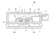
図1は、本発明の第1実施形態に係るマイクロホン100の外観を示す正面図及び底面図である。この場合、図1の(a)が正面図であり、(b)が底面図である。また、図2は、図1の(b)のA−A線を中心としたマイクロホン100の断面図である。図1及び図2に示すように、第1実施形態に係るマイクロホン100は、内部に空間を有し、また下部中央に音孔(以下、“筐体音孔”と呼ぶ)1h1が開けられた箱状の筐体1と、筐体1に収容される音響変換モジュール2と、音響変換モジュール2から出力される音声信号を外部機器(図示略)へ伝送するとともに、該外部機器からの電力を音響変換モジュール2へ供給するための配線3と、外部機器(図示略)との接続のためのワイヤーハーネス(図示略)に繋がるコネクタ4と、筐体1に開けられた筐体音孔1h1と音響変換モジュール2に開けられた音孔2hからの音漏れを防ぐためのシーリング用のパッキング5と、筐体1の筐体音孔1h1から筐体1の内部への水やごみの浸入を防ぐための防水膜6と、筐体1の筐体音孔1h1及び防水膜6を洗車時などの高圧水流から守るためのカバー部材7と、カバー部材7と筐体1との間に、筐体1に開けられた筐体音孔1h1の周囲に沿って離間配置され、カバー部材7を支持する4つの支柱部材8と、を備える。
(First embodiment)
1A and 1B are a front view and a bottom view showing the appearance of the
筐体1は、一面が開口した立方体状の容器部1aと、容器部1aの開口端を塞ぎ、中央部分には上述した筐体音孔1h1が開けられた方形板状の蓋部1bとから構成される。また、図2において、容器部1aの右側面には、上述した配線3を通すための貫通孔1h2が開けられている。また、図2において、音響変換モジュール2は、電気音響変換素子2aと、抵抗、コンデンサ、インダクタンス、IC(集積回路)及びトランジスタ等の表面実装部品2bと、表面実装部品2bを実装するための回路基板2cとを備える。回路基板2cの中央部には上述した音孔2hが開けられており、この音孔2h上に電気音響変換素子2aが配置される。また、回路基板2cの音孔2hの中心軸が筐体1の筐体音孔1h1の中心軸と一致するように、音響変換モジュール2が配置される。電気音響変換素子2aは、具体的にはECM(Electret Condenser Microphone)、MEMS(Micro Electro Mechanical System)技術あるいはマイク口マシニング技術を用いて製作される通称シリコンマイク、あるいはダイナミックマイクのいずれかが適宜選ばれる。
The casing 1 includes a
パッキング5には、筐体1の筐体音孔1h1と同径の貫通孔5hが開けられている。パッキング5は、貫通孔5hの軸心が回路基板2cの音孔2hの軸心及び筐体1の蓋部1bの筐体音孔1h1の軸心と一致するように配置される。
The
防水膜6は、筐体1の筐体音孔1h1を覆うようにして蓋部1bの表面に接着剤又は熱溶着等によって固定される。防水膜6には、PTFE(ポリテトラ・フルオロエチレン)などの材料が適宜選ばれる。カバー部材7は、筐体1の蓋部1bと略同じ大きさの平板形状を成し、筐体1の蓋部1bの表面から離間して配置される。カバー部材7には、防水膜6を覆う部分の外側に外部からの音を取り入れるための4つの音孔(以下、“カバー音孔”と呼ぶ)7h1〜7h4が開けられている。図1の(b)に示すように、カバー部材7の4つのカバー音孔7h1〜7h4は、筐体音孔1h1が設けられた筐体1の面を該面と直交する方向から見たときに筐体音孔1h1及び防水膜6が見えない(通常は、本実施形態のように筐体音孔1h1上に防水膜6が貼られるので、“防水膜6が見えない”)位置に配置される。即ち、カバー音孔7h1〜7h4から水等が浸入してきても、それが防水膜6に直接当たらない位置に配置される。4つのカバー音孔7h1〜7h4は、いずれも円弧状に形成され、同一円周上に一定の間隔で配置されている。なお、4つのカバー音孔7h1〜7h4は形状や個数は適宜変更してもかまわない。
The
支柱部材8は、円柱形状を成し、筐体1とカバー部材7の四隅に1つずつ配置されている。支柱部材8と筐体1の蓋部1b及び支柱部材8とカバー部材7は、それぞれ接着剤にて、又は嵌め込み、又は一体成型、又は熱溶着、レーザー溶着、ネジ止めによって固定される。
The
本実施形態に係るマイクロホン100は、上述したように構成されており、カバー部材7に開けられた4つのカバー音孔7h1〜7h4及びカバー部材7と筐体1の隙間から音を導入し、防水膜6を通して筐体1の筐体音孔1h1から電気音響変換素子2aに送り、電気音響変換素子2aで電気信号に変換する。変換された電気信号は、配線3を介し、コネクタ4に接続されるワイヤーハーネス(図示略)を通して外部機器(図示略)に送られる。
The
また、本実施形態に係るマイクロホン100においては、図3の(a)の断面図に示すように、洗車などの高圧な水流が正面から当たる場合、図1の(b)の底面図に示すように、カバー部材7のカバー音孔7h1〜7h4から防水膜6が見えないように、カバー音孔7h1〜7h4を配置しているので、カバー音孔7h1〜7h4を通った水流が防水膜6に直接当たることがない。これにより、洗車時のような高圧水流が防水膜6に加わることが無いため、防水膜6が損傷したりすることのない高い耐環境性を獲得できる。
Further, in the
また、本実施形態のマイクロホン100においは、図3の(b)の断面図に示すように、カバー部材7と筐体1の間に支柱部材8による隙間があるので、洗車などの高圧な水流が正面から当たる場合に、水流がカバー音孔7h1〜7h4から入り、その後は、カバー部材7と筐体1の隙間を通ってマイクロホン100の外に排出される。これにより、洗車時のような高圧水流が防水膜6に直接加わることが無いため、防水膜6が損傷したりすることのない高い耐環境性を獲得できる。また、カバー音孔7h1〜7h4から細い棒状の異物(針金・枝等)が侵入した場合でも当該異物による防水膜6の損傷が起こり難い。
In the
以上のように本実施形態に係るマイクロホン100によれば、音響変換モジュール2を収容する筐体1の筐体音孔1h1上に設けられた防水膜6を覆うとともに、音を通すための4つのカバー音孔7h1〜7h4を有するカバー部材7を備えたので、洗車時のような高圧水流が防水膜6に直接加わることが無いため、防水膜6が損傷したりすることのない高い耐環境性を獲得できる。
As described above, according to the
(第2実施形態)
次に、本発明の第2実施形態に係るマイクロホンについて説明する。
図4は、本発明の第2実施形態に係るマイクロホン110の構造を示す断面図である。同図に示すように、本実施形態に係るマイクロホン110は、前述した第1実施形態に係るマイクロホン100とは筐体の形状に一部違いがある。即ち、本実施形態に係るマイクロホン110は、筐体10の筐体音孔10h1の周辺部が、筐体音孔10h1の面に対して一段落ち込んだ凹状になっている。筐体音孔10h1の周辺部を凹状にすることで、筐体音孔10h1に配置した防水膜6も筐体10の表面に対して一段落ち込んだ位置となる。
(Second Embodiment)
Next, a microphone according to a second embodiment of the present invention will be described.
FIG. 4 is a cross-sectional view showing the structure of the
この構成により、図5の(a)の断面図に示すように、高圧水流がマイクロホン110の側面から当たっても、防水膜6がカバー部材7と筐体10の隙間から見えない位置に配置されていることから、カバー部材7と筐体10の隙間を通った直接の水流が防水膜6に当たることがない。これにより、洗車時のような高圧水流が防水膜6に直接加わることが無いため、防水膜6が損傷したりすることのない高い耐環境性を獲得できる。また、カバー部材7と筐体10の隙間に細い棒状の異物(針金・枝等)が侵入した場合でも防水膜6への異物による損傷が起こり難い。
With this configuration, as shown in the cross-sectional view of FIG. 5A, the
また、図5の(b)の断面図に示すように、マイクロホン110の外部から侵入し、筐体10の表面を伝う液体の粒(水滴および油滴等)20が防水膜6の周辺に留まり難くなるため、防水膜6が液体の粒20に浸ることで、防水膜6の材料が劣化することが起こり難い。
Further, as shown in the cross-sectional view of FIG. 5B, liquid particles (water droplets, oil droplets, etc.) 20 that enter from the outside of the
(第3実施形態)
次に、本発明の第3実施形態に係るマイクロホンついて説明する。
図6は、本発明の第3実施形態に係るマイクロホン120の外観を示す正面図及び底面図である。この場合、図6の(a)が正面図であり、(b)が底面図である。また、図7は、図6の(a)のB−B線断面図である。図6に示すように、本実施形態に係るマイクロホン120は、第1実施形態に係るマイクロホン100とは、カバー部材7と筐体1の間の隙間に壁部材11a及び11bを配置した点で異なっている。壁部材11a及び11bは、筐体1の4辺の周縁部それぞれに配置されている。この場合、筐体1の短辺側には短尺の壁部材11aが配置され、筐体1の長辺側には長尺の壁部材11bが配置される。
(Third embodiment)
Next, a microphone according to a third embodiment of the present invention will be described.
FIGS. 6A and 6B are a front view and a bottom view showing the appearance of the
この構成により、図7の断面図に示すように、防水膜6は、4つの壁部材11a,11bと支柱部材8によって、カバー部材7と筐体1の隙間から見えない位置になるので、洗車などの高圧な水流が側面から当たっても、カバー部材7と筐体1の隙間を通った直接の水流が防水膜6に当たることがない。これにより、洗車時のような高圧水流が防水膜6に直接加わることが無いため、防水膜6が損傷したりすることのない高い耐環境性を獲得できる。また、カバー部材7と筐体1の隙間に細い棒状の異物(針金・枝等)が侵入した場合でも防水膜6への異物による損傷が起こり難い。
With this configuration, as shown in the cross-sectional view of FIG. 7, the
なお、本発明のマイクロホンを用いることにより、耐環境性が高い、実用的な車両トランク開閉システムあるいは車両ドア開閉システムあるいは車両ライト照明システムあるいは音源方向推定装置を実現できる。 By using the microphone of the present invention, it is possible to realize a practical vehicle trunk opening / closing system, vehicle door opening / closing system, vehicle light illumination system, or sound source direction estimating device having high environmental resistance.
本発明は、車両外にいる発話者の音声の集音や、自車両に接近してくる他車両を検知することを目的とした車両に配置するマイクロホンとして有用である。 INDUSTRIAL APPLICABILITY The present invention is useful as a microphone disposed in a vehicle for the purpose of detecting the voice of a speaker who is outside the vehicle and detecting other vehicles approaching the host vehicle.
1,10 筐体
1h1,10h1 筐体音孔(音孔)
2 音響変換モジュール
2a 電気音響変換素子
2b 表面実装部品
2c 回路基板
2h 音孔
3 配線
4 コネクタ
5 パッキング
5h 貫通孔
6 防水膜
7 カバー部材
7h1〜7h4 カバー音孔
8 支柱部材
11a,11b 壁部材
100,110,120 マイクロホン
1,10 housing 1h1, 10h1 housing sound hole (sound hole)
2
Claims (3)
内部に空間を有するとともに一面に前記内部に通ずる音孔を有し、前記音孔に前記電気音響変換素子が位置するように前記音響変換モジュールを収容する筐体と、
前記筐体の音孔から前記筐体の内部への水やごみの浸入を防ぐ防水膜と、
前記筐体の音孔が設けられた面から離間して配置され、前記筐体の音孔が設けられた面を該面に直交する方向から見たときに前記防水膜が見えない位置に配置される少なくとも1つの音孔を有する平板形状のカバー部材と、
前記カバー部材を前記筐体に固定するための少なくとも1つの支柱部材と、
を備えるマイクロホン。 An acoustic conversion module in which various electronic components including an electroacoustic conversion element are mounted on a circuit board;
A housing that has a space inside and has a sound hole that communicates with the inside on one side, and that houses the acoustic conversion module so that the electroacoustic conversion element is positioned in the sound hole;
A waterproofing membrane that prevents water and dust from entering the housing from the sound holes of the housing;
Arranged at a position away from the surface provided with the sound hole of the housing, and at a position where the waterproof membrane cannot be seen when the surface provided with the sound hole of the housing is viewed from a direction orthogonal to the surface. A flat cover member having at least one sound hole;
At least one strut member for fixing the cover member to the housing;
A microphone equipped with.
Priority Applications (1)
| Application Number | Priority Date | Filing Date | Title |
|---|---|---|---|
| JP2018033419A JP2019149698A (en) | 2018-02-27 | 2018-02-27 | Microphone |
Applications Claiming Priority (1)
| Application Number | Priority Date | Filing Date | Title |
|---|---|---|---|
| JP2018033419A JP2019149698A (en) | 2018-02-27 | 2018-02-27 | Microphone |
Publications (1)
| Publication Number | Publication Date |
|---|---|
| JP2019149698A true JP2019149698A (en) | 2019-09-05 |
Family
ID=67850866
Family Applications (1)
| Application Number | Title | Priority Date | Filing Date |
|---|---|---|---|
| JP2018033419A Pending JP2019149698A (en) | 2018-02-27 | 2018-02-27 | Microphone |
Country Status (1)
| Country | Link |
|---|---|
| JP (1) | JP2019149698A (en) |
Cited By (2)
| Publication number | Priority date | Publication date | Assignee | Title |
|---|---|---|---|---|
| CN114885534A (en) * | 2021-02-05 | 2022-08-09 | 深圳富泰宏精密工业有限公司 | Electronic device |
| DE102020213964B4 (en) | 2020-11-06 | 2023-03-02 | Zf Friedrichshafen Ag | Device for detecting airborne noise for automotive applications, method for its production and automated driving system comprising such a device |
-
2018
- 2018-02-27 JP JP2018033419A patent/JP2019149698A/en active Pending
Cited By (2)
| Publication number | Priority date | Publication date | Assignee | Title |
|---|---|---|---|---|
| DE102020213964B4 (en) | 2020-11-06 | 2023-03-02 | Zf Friedrichshafen Ag | Device for detecting airborne noise for automotive applications, method for its production and automated driving system comprising such a device |
| CN114885534A (en) * | 2021-02-05 | 2022-08-09 | 深圳富泰宏精密工业有限公司 | Electronic device |
Similar Documents
| Publication | Publication Date | Title |
|---|---|---|
| JP6391053B2 (en) | Microphone | |
| US20070040231A1 (en) | Partially etched leadframe packages having different top and bottom topologies | |
| US10945060B2 (en) | Invisible headliner microphone | |
| US11310578B2 (en) | Water and dustproof external microphone apparatus | |
| US20080150104A1 (en) | Leadframe with different topologies for mems package | |
| US8724840B2 (en) | Offset acoustic channel for microphone systems | |
| US11638077B2 (en) | Invisible headliner microphone | |
| GB2200814A (en) | Background noise cancelling microphone | |
| US20210204044A1 (en) | Invisible microphone assembly for a vehicle | |
| JP2019149698A (en) | Microphone | |
| CN102131140B (en) | Micro-electro-mechanical systems (MEMS) microphone | |
| KR20220009867A (en) | Water proof microphone | |
| JP2010011340A (en) | Waterproofing structure, and microphone and speaker applied with waterproofing structure | |
| KR20230002340A (en) | Microelectromechanical systems (MEMS) microphone assembly | |
| JP2008092183A (en) | Microphone device and acoustic device | |
| JP2004297765A (en) | Microphone | |
| JP2007116620A (en) | Intercom | |
| EP1524881A1 (en) | Microphone | |
| JP2007060228A (en) | Silicon microphone package | |
| JP2001298784A (en) | Waterproof structure for microphone | |
| US20030168278A1 (en) | Housing for a hands-free directional microphone | |
| CN208015979U (en) | A kind of speaker | |
| JP2022118886A (en) | microphone unit | |
| JP2018117172A (en) | microphone | |
| JP2002152870A (en) | Speaker system |