EP4531082A1 - Container storage apparatus - Google Patents
Container storage apparatus Download PDFInfo
- Publication number
- EP4531082A1 EP4531082A1 EP23811538.0A EP23811538A EP4531082A1 EP 4531082 A1 EP4531082 A1 EP 4531082A1 EP 23811538 A EP23811538 A EP 23811538A EP 4531082 A1 EP4531082 A1 EP 4531082A1
- Authority
- EP
- European Patent Office
- Prior art keywords
- container
- bottom face
- side wall
- nozzle
- storage apparatus
- Prior art date
- Legal status (The legal status is an assumption and is not a legal conclusion. Google has not performed a legal analysis and makes no representation as to the accuracy of the status listed.)
- Pending
Links
Images





Classifications
-
- H—ELECTRICITY
- H10—SEMICONDUCTOR DEVICES; ELECTRIC SOLID-STATE DEVICES NOT OTHERWISE PROVIDED FOR
- H10P—GENERIC PROCESSES OR APPARATUS FOR THE MANUFACTURE OR TREATMENT OF DEVICES COVERED BY CLASS H10
- H10P72/00—Handling or holding of wafers, substrates or devices during manufacture or treatment thereof
- H10P72/30—Handling or holding of wafers, substrates or devices during manufacture or treatment thereof for conveying, e.g. between different workstations
- H10P72/34—Handling or holding of wafers, substrates or devices during manufacture or treatment thereof for conveying, e.g. between different workstations the wafers being stored in a carrier, involving loading and unloading
- H10P72/3404—Storage means
-
- H—ELECTRICITY
- H10—SEMICONDUCTOR DEVICES; ELECTRIC SOLID-STATE DEVICES NOT OTHERWISE PROVIDED FOR
- H10P—GENERIC PROCESSES OR APPARATUS FOR THE MANUFACTURE OR TREATMENT OF DEVICES COVERED BY CLASS H10
- H10P72/00—Handling or holding of wafers, substrates or devices during manufacture or treatment thereof
- H10P72/10—Handling or holding of wafers, substrates or devices during manufacture or treatment thereof using carriers specially adapted therefor, e.g. front opening unified pods [FOUP]
- H10P72/19—Handling or holding of wafers, substrates or devices during manufacture or treatment thereof using carriers specially adapted therefor, e.g. front opening unified pods [FOUP] closed carriers
- H10P72/1918—Handling or holding of wafers, substrates or devices during manufacture or treatment thereof using carriers specially adapted therefor, e.g. front opening unified pods [FOUP] closed carriers characterised by coupling elements, kinematic members, handles or elements to be externally gripped
-
- H—ELECTRICITY
- H10—SEMICONDUCTOR DEVICES; ELECTRIC SOLID-STATE DEVICES NOT OTHERWISE PROVIDED FOR
- H10P—GENERIC PROCESSES OR APPARATUS FOR THE MANUFACTURE OR TREATMENT OF DEVICES COVERED BY CLASS H10
- H10P72/00—Handling or holding of wafers, substrates or devices during manufacture or treatment thereof
- H10P72/10—Handling or holding of wafers, substrates or devices during manufacture or treatment thereof using carriers specially adapted therefor, e.g. front opening unified pods [FOUP]
- H10P72/19—Handling or holding of wafers, substrates or devices during manufacture or treatment thereof using carriers specially adapted therefor, e.g. front opening unified pods [FOUP] closed carriers
- H10P72/1922—Handling or holding of wafers, substrates or devices during manufacture or treatment thereof using carriers specially adapted therefor, e.g. front opening unified pods [FOUP] closed carriers characterised by the construction of the closed carrier
-
- H—ELECTRICITY
- H10—SEMICONDUCTOR DEVICES; ELECTRIC SOLID-STATE DEVICES NOT OTHERWISE PROVIDED FOR
- H10P—GENERIC PROCESSES OR APPARATUS FOR THE MANUFACTURE OR TREATMENT OF DEVICES COVERED BY CLASS H10
- H10P72/00—Handling or holding of wafers, substrates or devices during manufacture or treatment thereof
- H10P72/10—Handling or holding of wafers, substrates or devices during manufacture or treatment thereof using carriers specially adapted therefor, e.g. front opening unified pods [FOUP]
- H10P72/19—Handling or holding of wafers, substrates or devices during manufacture or treatment thereof using carriers specially adapted therefor, e.g. front opening unified pods [FOUP] closed carriers
- H10P72/1924—Handling or holding of wafers, substrates or devices during manufacture or treatment thereof using carriers specially adapted therefor, e.g. front opening unified pods [FOUP] closed carriers characterised by atmosphere control
- H10P72/1926—Handling or holding of wafers, substrates or devices during manufacture or treatment thereof using carriers specially adapted therefor, e.g. front opening unified pods [FOUP] closed carriers characterised by atmosphere control characterised by the presence of atmosphere modifying elements inside or attached to the closed carrier
-
- H—ELECTRICITY
- H10—SEMICONDUCTOR DEVICES; ELECTRIC SOLID-STATE DEVICES NOT OTHERWISE PROVIDED FOR
- H10P—GENERIC PROCESSES OR APPARATUS FOR THE MANUFACTURE OR TREATMENT OF DEVICES COVERED BY CLASS H10
- H10P72/00—Handling or holding of wafers, substrates or devices during manufacture or treatment thereof
- H10P72/30—Handling or holding of wafers, substrates or devices during manufacture or treatment thereof for conveying, e.g. between different workstations
- H10P72/32—Handling or holding of wafers, substrates or devices during manufacture or treatment thereof for conveying, e.g. between different workstations between different workstations
- H10P72/3221—Overhead conveying
-
- H—ELECTRICITY
- H10—SEMICONDUCTOR DEVICES; ELECTRIC SOLID-STATE DEVICES NOT OTHERWISE PROVIDED FOR
- H10P—GENERIC PROCESSES OR APPARATUS FOR THE MANUFACTURE OR TREATMENT OF DEVICES COVERED BY CLASS H10
- H10P72/00—Handling or holding of wafers, substrates or devices during manufacture or treatment thereof
- H10P72/30—Handling or holding of wafers, substrates or devices during manufacture or treatment thereof for conveying, e.g. between different workstations
- H10P72/32—Handling or holding of wafers, substrates or devices during manufacture or treatment thereof for conveying, e.g. between different workstations between different workstations
- H10P72/3222—Loading to or unloading from a conveyor
Definitions
- the present invention relates to a container storage apparatus.
- a container storage apparatus for temporarily storing containers that accommodate semiconductor wafers or other items may be provided (for example, see Patent Literature 1).
- the container storage apparatus may include a purger that supplies a purge gas, such as nitrogen gas, into the container.
- a purge gas such as nitrogen gas
- the container mentioned above is provided with a lid on a side face thereof for opening and closing the opening used for loading and unloading articles, and purge gas may leak from the periphery of the lid.
- the container storage apparatus disclosed in Patent Literature 1 is provided with a sucker that sucks the gas leaking from the lid while the purger supplies purge gas into the container.
- Patent Literature 1 Japanese Patent No. 6607314
- Patent Literature 1 The sucker disclosed in Patent Literature 1 is positioned opposite the lid of each container and has an opening larger than the lid to capture the gas leaking from the lid. As a result, the sucker not only becomes larger in size but also complicates the configuration of the container storage apparatus. Thus, there is a demand for a simpler configuration than conventional ones to suck the gas leaking from the lid.
- An object of the present invention is to provide a container storage apparatus capable of sucking gas leaking from a lid of a container, with a simpler configuration than conventional ones.
- a container storage apparatus comprises: a mounting table on which a container having a lid on a side face thereof is mounted; a purger that supplies a purge gas to the container; and a sucker that sucks gas leaking from the container, wherein the mounting table includes a bottom face on which the container is mounted, and a side wall extending upward from the bottom face and facing the lid of the container mounted on the bottom face, wherein the sucker sucks the gas leaking from a side face of the container where the lid is located through a first opening provided in the bottom face or the side wall, and wherein an upper end of the side wall is lower than an upper end of the lid of the container mounted on the bottom face.
- the sucker can be made smaller compared to conventional suckers that have an opening larger than the lid of the container. Additionally, gas that leaks from the periphery of the lid of the container can be sucked with a simpler configuration than conventional ones.
- the mounting table may be capable of mounting thereon a plurality of the containers, the bottom face and the side wall may be formed continuously across the plurality of containers, and a number of the first openings may be less than a number of the containers that can be mounted on the mounting table. According to such a configuration, the number of the first openings may be less than the number of the containers that can be mounted on the mounting table. It is thus possible to reduce the number of components such as covers that cover the first openings and pipes connected to the first openings and simplify the configuration further.
- the side wall may be provided so as to collectively enclose all four sides of the plurality of containers mounted on the bottom face. According to such a configuration, the side wall encloses a plurality of containers all together. It is thus possible to simplify the configuration further.
- a height of the upper end of the side wall may be set in a range from 80 mm to 120 mm from the bottom face or a bottom of the container. According to such a configuration, it is possible to suck the gas leaking from the container while keeping the height of the side wall low.
- the height of the upper end of the side wall may be set in a range from one-fourth to one-third of a height of the container mounted on the bottom face. According to such a configuration, even if the container tilts, the container abuts on the side wall, and thereby the container can be prevented from falling.
- the first opening may be provided in the bottom face between the side wall and the container mounted on the bottom face. According to such a configuration, the first opening is arranged below the lid side of the container. It is thus possible to efficiently suck the gas leaking from the periphery of the lid of the container through the first opening.
- the side wall may be provided so as to enclose all four sides of the container mounted on the bottom face. According to such a configuration, the gas leaking from the container accumulates on the inner side of the side wall. It is thus possible to suppress gas from diffusing below the container storage apparatus.
- the sucker may have a second opening provided in the bottom face and a nozzle that releases gas flowing out from an exhaust outlet formed in the bottom of the container to above the bottom face through the second opening and may suck the gas released from the nozzle through the first opening.
- the sucker 30 does not suck the interior of the container. It is thus possible to suppress the interior of the container from becoming a negative pressure.
- the nozzle may be arranged in a proximity of the first opening. According to such a configuration, the gas leaking from the periphery of the lid of the container and the gas released from the nozzle inside the container can be collectively sucked through the first opening.
- the mounting table may include a cover that covers the nozzle and the first opening and guides the gas released from the nozzle toward the first opening, and the cover may have a third opening formed in an upper face of the cover and guides the gas flowing in from the third opening toward the first opening. According to such a configuration, while suppressing the diffusion of gas released from the nozzle with the cover, the gas leaking from the container can be sucked through the first opening via the third opening.
- an XYZ coordinate system is used to describe the directions in each drawing.
- a plane that is parallel to a horizontal plane is defined as an XY plane.
- a direction perpendicular to the XY plane is denoted as Z direction.
- a direction indicated by an arrow is the positive (+) direction and a direction opposite to the direction indicated by the arrow is the negative (-) direction.
- a container storage apparatus 100 can, for example, receive a container 1 being transferred from an overhead transport vehicle 2 transporting the container 1, and is arranged near a ceiling C.
- the container storage apparatus 100 is fixed in place, suspended from the ceiling C by, for example, suspending brackets, and is arranged near the ceiling C.
- the container storage apparatus 100 is arranged, for example, at a position laterally offset from directly below the traveling rail (overhead track) R (see Fig. 3 ) for overhead transport vehicles 2.
- the container storage apparatus 100 is, for example, a buffer that temporarily stores containers 1 transported by the overhead transport vehicles 2.
- the container storage apparatus 100 may also be arranged directly below the traveling rail R.
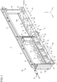
- Fig. 1 is a diagram showing an example of a schematic configuration of the container storage apparatus 100 according to the embodiment.
- Fig. 2 is a side view of a portion of the container 1 stored in the container storage apparatus 100.
- Fig. 3 is a diagram showing the process of transporting the container 1 to the container storage apparatus 100.
- the container storage apparatus 100 is capable of storing a plurality of containers 1.
- the container 1 accommodates articles such as wafers and reticles used for manufacturing semiconductor devices.
- the container 1 is, for example, a FOUP (Front Opening Unified Pod), a SMIF pod, a reticle pod, or the like, the interior of which can be purged with a purge gas.
- the container 1 may have another form that can be transported by the overhead transport vehicle 2.
- the container 1 includes a main body 1a, an opening 1b, a lid 1c, and a flange 1g.
- the main body 1a includes recesses 1d formed on the bottom side thereof for positioning.
- the main body 1a has an inlet 1e for gas and an exhaust outlet 1f for gas on the bottom side.
- the inlet 1e and the exhaust outlet 1f are each arranged in the proximity of the end in the X direction on the bottom side of the main body 1a.
- the inlet 1e and the exhaust outlet 1f each allow communication between the interior and the exterior of the main body 1a.
- the inlet 1e is used to introduce a purge gas into the main body 1a.
- the exhaust outlet 1f is used to expel gases within the main body 1a, including the purge gas, from the interior of the main body 1a.
- the inlet 1e and the exhaust outlet 1f may each be provided with a check valve not shown in the drawings to prevent backflow.
- the opening 1b is provided so as to face the horizontal direction (+Y direction). Articles such as wafers are placed inside the container 1 through the opening 1b.
- the lid 1c is provided for opening and closing the opening 1b and is provided on the container 1 in a detachable manner. Even if the lid 1c is tightly attached to the main body 1a, a gap still remains between the main body 1a and the lid 1c, allowing the possibility of purge gas or other substances leaking from the gap.
- a flange 1g is provided at the top of the container 1.
- the flange 1g is grasped by the overhead transport vehicle 2 for transportation.
- the container 1 is transported by the overhead transport vehicle 2 from the container storage apparatus 100 to a processing apparatus (not shown in the drawings) and from the processing apparatus to the container storage apparatus 100.
- This processing apparatus is, for example, a film forming device, a coater/developer, an exposure device, or an etching device, and performs various processes during the manufacturing of devices (for example, semiconductor devices).
- the container storage apparatus 100 is arranged, for example, on a transport route along which the containers 1 are transported and is used to temporarily store the containers 1.
- the overhead transport vehicle 2 travels along the traveling rail R by the driving force of a traveler 4.
- the traveling rail R is arranged in the vicinity of the ceiling C in a state of being suspended from the ceiling C of, for example, a clean room by means of suspending brackets Ra, and extends in the X direction.
- the overhead transport vehicle 2 includes a main body 3 and the traveler 4.
- the traveler 4 has wheels 4a, a driving source (not shown in the drawings) such as an electric rotary motor or a linear motor that drives the wheels 4a, and an encoder (not shown in the drawings).
- the wheels 4a are arranged so as to roll on rail surfaces provided on the inner side of the traveling rail R.
- the encoder detects the rotation speed of the wheels 4a and outputs the detection results to a controller (not shown in the drawings) included in the main body 3.
- the controller controls the drive source on the basis of the detection results of the encoder and controls the speed and so forth of the overhead transport vehicle 2.
- the main body 3 is attached to a coupler 3a extending downward from the traveler 4.
- the main body 3 is suspended from the traveler 4 via the coupler 3a.
- the main body 3 is capable of accommodating the container 1 therein.
- the main body 3 includes a lateral extender 5, an elevator 6, and a grasper 7.
- the lateral extender 5 is provided on the upper part of the main body 3.
- the lateral extender 5 changes the state of the container 1 between being accommodated inside the main body 3 and being extended laterally.
- the lateral extender 5 includes a base 5a and lateral extensions 5b.
- the base 5a may be provided with a rotary member that has an electric motor or the like and can rotate around the Z direction (vertical direction) being its rotation axis. The rotation of the rotary member causes the lateral extender 5 to rotate, allowing the lateral extension direction of the lateral extender 5 to change.
- the lateral extensions 5b are attached to the lower face side of the base 5a.
- the lateral extensions 5b are, for example, a plurality of movable plates arranged in a manner of being stacked in the Z direction.
- the plurality of lateral extensions 5b can be moved in the +Y direction or -Y direction (perpendicular to the traveling direction of the traveler 4) along a guide (not shown in the drawings) by the driving force of a power device such as an electric motor (not shown in the drawings).
- the elevator 6 is attached to the lowermost lateral extension 5b.
- the lateral extender 5 can move the movable plates, which are the lateral extensions 5b, using a driver and slide the elevator 6 and the grasper 7, which are attached to the lowermost lateral extension 5b, in a direction perpendicular to the traveling direction.
- the elevator 6 is controlled by the controller to raise or lower the grasper 7 at a predetermined speed. Also, the elevator 6 is controlled by the controller to maintain the grasper 7 at a target height.
- the grasper 7 suspends and holds the container 1 by grasping the flange 1c of the container 1.
- the grasper 7 is, for example, a chuck having claws movable in the horizontal direction.
- the overhead transport vehicle 2 can perform lateral transfer to deliver or receive the container 1 to or from a target position in the container storage apparatus 100 by sliding the lateral extensions 5b to laterally extend the elevator 6 and lowering the grasper 7 using the elevator 6.
- the overhead transport vehicle 2 can deliver or receive the container 1 by lowering the grasper 7 using the elevator 6 without sliding the lateral extensions 5b.
- the container storage apparatus 100 includes purgers 10, a mounting table 20, and suckers 30.
- the purger 10 supplies a purge gas to the container 1 stored in the container storage apparatus 100.
- the purgers 10 are provided on the mounting table 20.
- the purger 10 is provided for each container 1 stored in the container storage apparatus 100, however, the present invention is not limited to this example.
- the purger 10 may be provided for some of the containers 1 stored in the container storage apparatus 100.
- the purger 10 includes, for example, a purge nozzle 10a and a flow rate controller (not shown in the drawings) such as a mass flow controller that controls the flow rate of the purge gas.
- the purge nozzle 10a is provided in a state of projecting upward from the mounting table 20.
- the purge nozzle 10a is arranged so as to be connected to the inlet 1e of the container 1 when the container 1 is mounted on the mounting table 20.
- the purge nozzle 10a is connected to a supplier 11 (see Fig. 6 ) of the purge gas via a pipe 12 (see Fig. 6 ), which will be described later.
- the purge gas is a gas that is inert to the articles stored in the container 1, such as nitrogen gas, for example.
- the purger 10 supplies the purge gas from the supplier 11 through the pipe 12 to the interior of the container 1 from the inlet 1e and purges the interior of the container 1 with the purge gas.
- the mounting table 20 is arranged at a position laterally offset from directly below the track of the overhead transport vehicle 2.
- the container 1 is mounted on the mounting table 20 from the front side of the container storage apparatus 100 by a lateral transfer performed by the overhead transport vehicle 2.
- the front side of the container storage apparatus 100 is the side facing the overhead transport vehicle 2.
- the number of mounting tables 20 arranged in the container storage apparatus 100 is two and they are arranged side by side in the X direction, however, the invention is not limited to this example, and one or three or more mounting tables 20 may be arranged in the container storage apparatus 100.
- a plurality of containers 1 can be mounted on one mounting table 20.
- a single mounting table 20 may be configured to allow only one container 1 to be mounted thereon.
- Fig. 1 shows a state where four containers 1 are mounted on one of the mounting tables 20, and no containers 1 are mounted on the other mounting table 20.
- the mounting tables 20 may be arranged in parallel instead of being arranged in series in the X direction.
- the mounting table 20 includes a bottom face 21, a side wall 22, support columns 26, and a frame 27.
- the container 1 is to be mounted on the bottom face 21.
- a plurality of pins (kinematic pins) 17 for positioning the container 1 are provided on the bottom face 21.
- the pins 17 are arranged so as to correspond to the positions of the recesses 1d provided in the bottom of the container 1 and can fit into the recesses 1d.
- the pins 17 fit into the recesses 1d of the container 1, thereby positioning the container 1.
- the shape and number of the recesses 1d and the pins 17 are arbitrary.
- the side wall 22 is provided so as to enclose all four sides of one or more containers 1 mounted on the bottom face 21.
- the side wall 22 is provided so as to extend vertically upward from the bottom face 21.
- the side wall 22 is, for example, a plate-shaped member that encloses the periphery of the containers 1.
- the side wall 22 includes a first side wall 23, a second side wall 24, and a pair of third side walls 25.
- the first side wall 23 extends upward from the bottom face 21 and faces the lid 1c of the container 1 mounted on the bottom face 21.
- the first side wall 23 is provided on the front side of the container storage apparatus 100.
- the first side wall 23 may be formed continuously across the range corresponding to the plurality of containers 1.
- the invention is not limited to this example, and the first side wall 23 may be provided for each container 1.
- An upper end 23a of the first side wall 23 is lower than an upper end 1h of the lid 1c of the container 1 mounted on the bottom face 21.
- a height H2 of the upper end 23a of the first side wall 23 is lower than a height H1 of the upper end 1h of the lid 1c.
- the height H1 and the height H2 may be heights from the bottom of the container 1 or may be heights from the bottom face 21.
- the upper end 23a of the first side wall 23 is set in a range from 80 mm to 120 mm from the bottom of the container 1 or the bottom face 21.
- the height of the upper end 23 of the side wall 23 may be set in a range from one-fourth to one-third of the height of the container 1 mounted on the bottom face 21.
- the lid 1c even if the lid 1c inadvertently comes off from the container 1 in storage, the lid 1c will be restrained as it abuts on the upper end 23a of the first side wall 23. It is thus possible to prevent the lid 1c from falling off.
- the second side wall 24 is provided on the rear side, opposite the front side of the container storage apparatus 100.
- the second side wall 24 is provided on the side opposite the front side, where the front is defined as the face facing the overhead transport vehicle 2.
- the height of the upper end 24a of the second side wall 24 may be approximately the same as the height of the container 1 mounted on the bottom face 21 or may be a different height.
- the height of the upper end 24a of the second side wall 24 may be the same as the height of the upper end 23a of the first side wall 23.
- the second side wall 24 has the function of preventing the gas leaking from the container 1 from flowing around to the rear side and falling downward from the bottom face 21, while also preventing the container 1 mounted on the bottom face 21 from falling off the bottom face 21.
- the third side walls 25 are provided on the left and right sides of the container storage apparatus 100, that is, on both ends of the container storage apparatus 100 in the X direction.
- the third side walls 25, along with the support columns 26 described later, are provided on the +X side and -X side of the container 1.
- the third side walls 25 are provided so as to connect ends of the first side wall 23 to ends of the second side wall 24.
- the ends of the first side wall 23, the second side wall 24, and the pair of third side walls 25 enclose the plurality of containers 1.
- the ends of the first side wall 23, the second side wall 24, and the pair of third side walls 25 are arranged so as to coincide with the outer edge of the mounting table 20 in a plan view.
- the height of the upper ends 25a of the third side walls 25 may be approximately the same as the height of the container 1 mounted on the bottom face 21 or may be a different height.
- the height of the upper ends 25a of the third side walls 25 may be the same as the height of the upper end 23a of the first side wall 23.
- the support columns 26 are provided on the +X side and the -X side of the mounting table 20 and support the mounting table 20.
- the support columns 26 are connected to the bottom face 21, and as described above, a part of each support column 26 is used as a part of the third side wall 25.
- the frame 27 is provided at the upper ends of the support columns 26 so as to connect the two support columns 26 together.
- the frame 27 is arranged above the bottom face 21 and extends in the X direction.
- the frame 27 is suspended from the ceiling C by suspending brackets not shown in the drawings. By adjusting these suspending brackets, the height position of the frame 27 (container storage apparatus 100) can be adjusted.
- the sucker 30 sucks the purge gas leaking from the periphery of the lid 1c of the container 1.
- the purge gas purged into the container 1 may, in some cases, leak from the attachment part or other parts of the lid 1c of the container 1.
- the purge gas may affect human health, depending on the type or concentration of the gas.
- the purge gas leaking from the container 1 may cause deterioration of the surrounding environment.
- the concentration of the purge gas leaking from the container 1 may increase in the atmosphere around the container 1.
- a so-called downflow an air current in which clean air flows downward from a fan filter unit arranged in an upper part of the building, may be present, and if the container 1 is stored in an open environment, the downflow may cause the purge gas to flow toward the ground, resulting in the increased purge gas concentration near the ground.
- the sucker 30 according to the present embodiment sucks and recovers the purge gas leaking from the container 1 and prevents the purge gas from diffusing around the container storage apparatus 100 or near the ground.
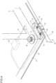
- Fig. 4 is a diagram showing an example of the sucker 30.
- the sucker 30 includes a suction portion 31, a pipe 32, and a pipe 33.
- the suction portion 31 includes the exhaust nozzle 40, a pipe 41, a flow rate measurer 42, a first nozzle 50, a second nozzle 60, and a cover 70.
- the suction portion 31 is provided for each container 1.
- the invention is not limited to this example, and the suction portion 31 may be provided for each set of multiple containers 1.
- the exhaust nozzle 40 releases the gas in the container 1 through the exhaust outlet 1f of the container 1 (see Fig. 6 ).
- the exhaust nozzle 40 is provided on the bottom face 21 so as to be connected to the exhaust outlet 1f of the container 1 when the container 1 is mounted on the mounting table 20.
- the gas in the interior of the container 1 flows out of the container 1 through the exhaust nozzle 40 and is sucked by the sucker 30.
- the exhaust nozzle 40 is an example of the second opening.
- the pipe 41 is provided, for example, on the back side of the bottom face 21.
- One end of the pipe 41 is connected to the exhaust nozzle 40 and the other end is connected to the second nozzle 60.
- the flow rate measurer 42 is provided, for example, on the back side of the bottom face 21.
- the flow rate measurer 42 is provided midway through the pipe 41 and measures the flow rate of the gas discharged from the exhaust nozzle 40 and flowing through the pipe 41.
- the flow rate measurer 42 may be, for example, a mass flow controller or the like.
- the first nozzle 50 is provided, for example, on the bottom face 21 or in the bottom face 21.
- the first nozzle 50 is provided on the bottom face 21 between the first side wall 23 and the container 1 mounted on the bottom face 21.
- the first nozzle 50 is arranged inside the cover 70 attached to the bottom face 21.
- the first nozzle 50 sends the gas inside the cover 70 to the pipe 32 through a connection 51 such as a joint.
- the connection 51 allows communication between the first nozzle 50 and the pipe 32.
- the first nozzle 50 projects upward from the upper surface of the bottom face 21 inside the cover 70.
- the first nozzle 50 may be provided with a check valve to prevent backflow of the gas. It should be noted that the exhaust nozzle 50 is an example of the first opening.
- the second nozzle 60 is provided on the bottom face 21.
- the second nozzle 60 is provided on the bottom face 21 between the first side wall 23 and the container 1 mounted on the bottom face 21.
- the second nozzle 60 projects upward from the upper surface of the bottom face 21 inside the cover 70.
- the second nozzle 60 is arranged in the vicinity of the first nozzle 50.
- the first nozzle 50 and the second nozzle 60 are arranged in line along the X direction, for example.
- the second nozzle 60 may be provided with a check valve to prevent backflow of the gas.
- the second nozzle 60 releases the gas flowing out from the exhaust outlet 1f on the bottom of the container 1 toward above the bottom face 21 via the exhaust nozzle 40.
- the second nozzle 60 communicates with the pipe 41 and releases the gas flowing through the pipe 41 into the cover 70.
- the cover 70 is provided on the bottom face 21 between the first side wall 23 and the container 1 mounted on the bottom face 21.
- the cover 70 is provided so as to cover the first nozzle 50 and the second nozzle 60.
- the cover 70 guides the gas released from the second nozzle 60 to flow into the pipe 32 through the first nozzle 50. In other words, the cover 70 guides the gas released from the second nozzle 60 toward the first nozzle 50.
- Fig. 5 is a diagram showing an example of the cover 70.
- the cover 70 includes a third opening 71, a first space 72, a second space 73, and a third space 74.
- the third opening 71 is formed in the upper face of the cover 70.
- the third opening 71 is a circular hole, however, the shape thereof is not particularly limited.
- the third opening 71 is a hole for introducing a gas G3 leaking from the periphery of the lid 1c of the container 1 into the cover 70.
- the upper face of the cover 70 is lower than the upper end 23a of the first side wall 23. That is to say, the third opening 71 is provided at a position lower than the upper end 23a of the first side wall 23.
- the gas G3 leaking from the periphery of the lid 1c of the container 1 is introduced into the cover 70 through the third opening 71 and is sucked by the first nozzle 50.
- the first space 72 is a space inside the cover 70, and a gas G2 from the second nozzle 60 is released thereinto.
- the first space 72 communicates with the pipe 41 via the second nozzle 60.
- the first space 72 is, for example, a cylindrical space.
- the second space 73 connects the first space 72 and the third space 74.
- the second space 73 guides the gas G2 in the first space 72 to the third space 74.
- the third space 74 connects the third opening 71 and the first nozzle 50 (first opening).
- the third space 74 is, for example, a cylindrical space.
- the third space 74 guides the gas G3 flowing in from the third opening 71 to the first nozzle 50.
- the third space 74 is connected to the first space 72 via the second space 73. Therefore, the third space 74 guides the gas G2 flowing into the second space 73 from the first space 72 to the first nozzle 50.
- the cover 70 has the function of guiding the gas G2 released from the second nozzle 60 to the first nozzle 50, and the function of guiding the gas G3 leaking from the periphery of the lid 1c of the container 1 from the third opening 71 to the first nozzle 50.
- the pipe 32 communicates with the first nozzle 50 via the connection 51.
- the pipe 32 is connected to the pipe 33 as shown in Fig. 1 .
- Fig. 1 shows a configuration in which one first nozzle 50 and the pipe 32 are connected, and the connections between other first nozzles 50 and pipes 32 are omitted.
- the gases G2, G3 sucked from the first nozzle 50 are sent to the pipe 33 via the pipe 32.
- the pipe 32 includes a portion extending in the X direction along the bottom of the bottom face 21 and a portion extending in the Z direction along the support column 26.
- the pipe 32 is connected to the pipe 33.
- the pipe 33 is attached to the frame 27.
- the pipe 33 extends along the frame 27 in the X direction.
- the gases G2, G3 are sent from the pipe 32 to the pipe 33 and are discharged from the pipe 33 to the outside.
- the sucker 30 includes a suction force generator that is connected to the pipe 33 and generates a suction force for sucking the gases G2, G3.
- the sucker 30 may be configured such that the pipe 33 is connected to a suction force generator (line) that is already installed in a factory or the like.
- the timing of sucking the gases G2, G3 is not particularly limited.
- suction may be performed in conjunction with the operation of the purger 10.
- the sucker 30 may start suction at a time when the container 1 is mounted on the bottom face 21 and the purger 10 starts supplying the purge gas to the container 1.
- the suction of the sucker 30 may be performed continuously without being in conjunction with the purger 10 or may be performed at a timing controlled by the operator.
- Fig. 6 is a diagram schematically showing the flows of the purge gases G2, G3 sucked by the sucker 30.
- Fig. 7 is a flowchart showing an example of a container storage method according to the embodiment.
- the overhead transport vehicle 2 mounts the container 1 at a target position on the bottom face 21 through lateral transfer (Step S101).
- Step S101 first, the overhead transport vehicle 2 moves to the container storage apparatus 100 and stops to the side of the target position where the container 1 is to be mounted.
- the overhead transport vehicle 2 laterally extends the container 1 to directly above the mounting table 20 by means of the lateral extender 5.
- the overhead transport vehicle 2 lowers the grasper 7 by means of the elevator 6, thereby mounting the container 1 at the target position on the bottom face 21.
- the container 1 is mounted on the bottom face 21.
- the operation of the overhead transport vehicle 2 is controlled by a controller (not shown in the drawings) included in the overhead transport vehicle 2.
- This controller acquires information related to the storage location (target position) of the container 1 from a host controller or the like and controls the overhead transport vehicle 2 to mount the container 1 at the storage location.
- the controller acquires information related to the storage location (target position) of the container 1 from a host controller or the like and controls the overhead transport vehicle 2 to mount the container 1 at the storage location.
- Step S102 the supply of a purge gas G1 to the container 1 mounted on the bottom face 21 is started (Step S102).
- Step S102 when the container 1 is mounted on the bottom face 21, the inlet 1e provided on the bottom of the container 1 and the purge nozzle 10a provided on the bottom face 21 are connected to each other.
- the purger 10 supplies the purge gas G1 sent from the supplier 11 into the container 1 via the pipe 12 and the purge nozzle 10a, as shown in Fig. 6 .
- the supply amount of the purge gas G1 is controlled by a controller (not shown in the drawings) included in the purger 10 on the basis of the flow rate of the purge gas G1 flowing through the pipe 12, for example.
- Step S103 When the supply of the purge gas G1 performed by the purger 10 is started, the sucker 30 starts sucking gas (Step S103).
- the container 1 When the container 1 is mounted on the bottom face 21, the exhaust outlet 1f provided on the bottom of the container 1 and the exhaust nozzle 40 provided on the bottom face 21 are connected to each other.
- the purge gas G1 is supplied into the container 1 in Step S102, the internal pressure of the container 1 increases.
- the gas G2 in the container 1 is discharged from the exhaust outlet 1f and is released from the second nozzle 60 into the cover 70 through the exhaust nozzle 40 and the pipe 41.
- Step S103 the gas G2 released into the cover 70 is sucked through the first nozzle 50.
- the gas G3 may leak from the periphery of the lid 1c of the container 1.
- the gas G3 accumulates on the inner side of the side wall 22 enclosing the container 1 and is sucked from the first nozzle 50 through the third opening 71 of the cover 70.
- the gases G2, G3 sucked by the first nozzle 50 are discharged through the pipes 32, 33 to the outside of the container storage apparatus 100 (or to the outside of the factory building).
- the suction of the gases G2, G3 performed by the sucker 30 may be performed when the purge gas is supplied to the container 1 or may be performed continuously while the container 1 is in storage. While the container 1 is stored in the container storage apparatus 100, the sucker 30 may be operated at predetermined intervals on the basis of the output of a timer (not shown in the drawings) or a similar device. The process is concluded through the series of operations described above.
- the sucker 30 does not have an opening larger than the lid 1c of the container 1, and thus the sucker 30 can be made smaller and configured in a simpler manner to suck the gases G2, G3 leaking from the container 1.
- the upper end 23a of the first side wall 23 is lower than the upper end of the lid 1c of the container 1 mounted on the bottom face 21, and it is thus possible to reduce the amount of vertical movement of the grasper 7 during lateral transfer of the container 1 on the overhead transport vehicle 2.
- the container 1 is transferred to and from the container storage apparatus 100 through the lateral transfer of the overhead transport vehicle 2 as described above.
- the upper end 23a of the first side wall 23 is lower than the upper end 1h of the lid 1c of the container 1 mounted on the bottom face 21, and it is thus possible to reduce the amount of vertical movement of the grasper 7 during lateral transfer of the container 1, allowing the container 1 to be transferred efficiently.
- the side wall 22 is provided to enclose the container 1, the gas G3 leaking from the periphery of the lid 1c of the container 1 accumulates on the inner side of the side wall 22 and is sucked by the first nozzle 50. This suppresses the gases G2, G3 from diffusing into the operator's area of activity below the mounting table 20.
- the first nozzle 50 (the third opening 71 of the cover 70) is provided on the bottom face 21 between the side face of the container 1 on the lid 1c side and the first side wall 23.
- the fist nozzle 50 is closer to the lid 1c of the container 1, and this enables efficient suction of the gas G3 leaking from the periphery of the lid 1c of the container 1 through the first nozzle 50.
- the gas G2 is discharged from the exhaust outlet 1f when the purge gas G1 is supplied to the container 1 along with the gas G3 leaked from the periphery of the lid 1c of the container 1. This eliminates the need for a gas recovery device or a similar device to recover the gas G2 discharged from the exhaust outlet 1f, thereby reducing the manufacturing cost of the container storage apparatus 100.
- the container storage apparatus 100 is typically installed in a clean room in which a downflow is present. Therefore, due to this downflow, the gas G3 leaking from the periphery of the lid 1c of the container 1 accumulates more efficiently on the inner side of the side wall 22 and is sucked through the first nozzle 50.
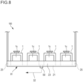
- FIG. 8 is a diagram showing a first modified example of the sucker 30.
- the configurations similar to those in the above embodiment are assigned with the same reference signs and the descriptions thereof are omitted or simplified.
- the number of first nozzles 50 may be less than the number of containers 1 mounted on the bottom face 21.
- one first nozzle 50 may be provided on the bottom face 21 for multiple containers 1.
- the side wall 22 is provided so as to enclose the multiple containers 1, and one first nozzle 50 is provided on the inner side of the side wall 22. Therefore, the gas G3 leaking from the periphery of the lid 1c of each of the multiple containers 1 is collectively accumulated on the inner side of the side wall 22.
- the cover 70 is provided on the inner side of the side wall 22, with one cover corresponding to one first nozzle 50.
- the pipe 41 is connected from each exhaust nozzle 40 of the multiple containers 1 to a single second nozzle 60, and the gas G2 from the multiple containers 1 is sent collectively to the one second nozzle 60 and then released into the cover 70.
- the single first nozzle 50 sucks the gas G3 accumulated on the inner side of the side wall 22 and the gas G2 released into the cover 70 and discharges them to the outside.
- the first modified example provides the effects similar to those of the above embodiment, and the gases G2, G3 from multiple containers 1 are sucked by fewer first nozzles 50 than the number of containers 1. It is thus possible, compared to the above embodiment, to reduce the number of the first nozzles 50, the pipes 32, and other associated components, and the manufacturing cost of the container storage apparatus 100.
- FIG. 9 is a diagram showing a second modified example of the sucker 30.
- the configurations similar to those in the above embodiment are assigned with the same reference signs and the descriptions thereof are omitted or simplified.
- the first nozzle 50 (first opening) may be provided in the first side wall 23 instead of the bottom face 21. It is preferable that the first nozzle 50 be provided in a lower part of the first sidewall 23 near the bottom face 21.
- the number of first nozzles 50 in the second modified example may be less than the number of containers 1 mounted on the mounting table 20, as in the above first modified example.
- the second nozzle 60 is provided in the bottom face 21 so as to release the gas G2 upward, for example.
- a cover or the like may be provided above the second nozzle 60 to block the flow of the gas G2.
- the gas G2 sent from the exhaust nozzle 40 is released from the second nozzle 60 toward above the bottom face 21 and accumulated on the inner side of the side wall 22.
- the gas G3 leaking from the periphery of the lid 1c of the container 1 is also accumulated on the inner side of the side wall 22 in a similar manner.
- the first nozzle 50 sucks the gases G2, G3 accumulated on the inner side of the side wall 22 and discharges them to the outside.
- the second modified example it provides the effects similar to those of the above embodiment. Since the first nozzle 50 is provided in the side wall 22, even if there is no space for the first nozzle 50 to be arranged in the bottom face 21, it is still possible to reliably suck the gases G2, G3 accumulating on the inner side of the side wall 22.
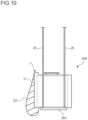
- Fig. 10 is a schematic diagram showing a state of the gas G3 in the periphery of the lid 1c of the container 1 stored in a container storage apparatus 100A according to a comparative example.
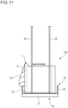
- Fig. 11 is a schematic diagram showing a state of the gas G3 in the periphery of the lid 1c of the container 1 stored in the container storage apparatus 100 according to the embodiment.
- Fig. 10 and Fig. 11 show a state of the gas G3 in an environment where a downflow is present.
- the container storage apparatus 100A does not have a configuration corresponding to the sucker 30. Therefore, as shown in Fig. 10 , the gas G3 leaking from the periphery of the lid 1c of the container 1 diffuses so as to spread along the lower side of a mounting table 20A, on which the container 1 is mounted. On the other hand, since the container storage apparatus 100 of the present embodiment includes the side wall 22, the gas G3 leaking from the periphery of the lid 1c of the container 1 is guided to the region between the lid 1c and the first side wall 23 and accumulates on the inner side of the side wall 22.
- the gas G3 accumulated on the inner side of the side wall 22 is sucked through the first nozzle 50. It should be noted that illustration of the first nozzle 50 is omitted in Fig. 11 . Therefore, the gas G3 diffusing downward from the side wall 22 to the outer side is drawn to the inner side of the side wall 22, thereby preventing the gas G3 from diffusing downward from the bottom face 21. As a result, according to the present embodiment, it is confirmed that the diffusion of the gas G3 below the container storage apparatus 100 is suppressed.
Landscapes
- Container, Conveyance, Adherence, Positioning, Of Wafer (AREA)
- Filling Or Discharging Of Gas Storage Vessels (AREA)
Abstract
[Problem] To provide a container storage apparatus capable of sucking gas leaking from a lid of a container with a simpler configuration than conventional ones.[Means to Solve Problem] A container storage apparatus 10 comprises: a mounting table 20 on which a container 1 having a lid 1c on a side face thereof is mounted; a purger 10 that supplies a purge gas to the container 1; and a sucker 30 that sucks gas leaking from the container 1. The mounting table 20 includes a bottom face 21 on which the container 1 is mounted, and a side wall 23 extending upward from the bottom face and facing the lid of the container mounted on the bottom face. The sucker 30 sucks gas leaking from a side face of the container 1 where the lid 1c is located through a first opening 50 provided in the bottom face 21 or the side wall. An upper end 23 of the side wall 23 is lower than an upper end 1h of the lid 1c of the container 1 mounted on the bottom face 21.
Description
- The present invention relates to a container storage apparatus.
- In semiconductor manufacturing factories, a container storage apparatus for temporarily storing containers that accommodate semiconductor wafers or other items may be provided (for example, see Patent Literature 1). For example, the container storage apparatus may include a purger that supplies a purge gas, such as nitrogen gas, into the container. The container mentioned above is provided with a lid on a side face thereof for opening and closing the opening used for loading and unloading articles, and purge gas may leak from the periphery of the lid. For this reason, the container storage apparatus disclosed in
Patent Literature 1 is provided with a sucker that sucks the gas leaking from the lid while the purger supplies purge gas into the container. - [Patent Literature 1]
Japanese Patent No. 6607314 - The sucker disclosed in
Patent Literature 1 is positioned opposite the lid of each container and has an opening larger than the lid to capture the gas leaking from the lid. As a result, the sucker not only becomes larger in size but also complicates the configuration of the container storage apparatus. Thus, there is a demand for a simpler configuration than conventional ones to suck the gas leaking from the lid. - An object of the present invention is to provide a container storage apparatus capable of sucking gas leaking from a lid of a container, with a simpler configuration than conventional ones.
- A container storage apparatus according to an aspect of the present invention comprises: a mounting table on which a container having a lid on a side face thereof is mounted; a purger that supplies a purge gas to the container; and a sucker that sucks gas leaking from the container, wherein the mounting table includes a bottom face on which the container is mounted, and a side wall extending upward from the bottom face and facing the lid of the container mounted on the bottom face, wherein the sucker sucks the gas leaking from a side face of the container where the lid is located through a first opening provided in the bottom face or the side wall, and wherein an upper end of the side wall is lower than an upper end of the lid of the container mounted on the bottom face.
- According to the container storage apparatus of the above aspect, the sucker can be made smaller compared to conventional suckers that have an opening larger than the lid of the container. Additionally, gas that leaks from the periphery of the lid of the container can be sucked with a simpler configuration than conventional ones.
- The mounting table may be capable of mounting thereon a plurality of the containers, the bottom face and the side wall may be formed continuously across the plurality of containers, and a number of the first openings may be less than a number of the containers that can be mounted on the mounting table. According to such a configuration, the number of the first openings may be less than the number of the containers that can be mounted on the mounting table. It is thus possible to reduce the number of components such as covers that cover the first openings and pipes connected to the first openings and simplify the configuration further. The side wall may be provided so as to collectively enclose all four sides of the plurality of containers mounted on the bottom face. According to such a configuration, the side wall encloses a plurality of containers all together. It is thus possible to simplify the configuration further. A height of the upper end of the side wall may be set in a range from 80 mm to 120 mm from the bottom face or a bottom of the container. According to such a configuration, it is possible to suck the gas leaking from the container while keeping the height of the side wall low. The height of the upper end of the side wall may be set in a range from one-fourth to one-third of a height of the container mounted on the bottom face. According to such a configuration, even if the container tilts, the container abuts on the side wall, and thereby the container can be prevented from falling.
- The first opening may be provided in the bottom face between the side wall and the container mounted on the bottom face. According to such a configuration, the first opening is arranged below the lid side of the container. It is thus possible to efficiently suck the gas leaking from the periphery of the lid of the container through the first opening. The side wall may be provided so as to enclose all four sides of the container mounted on the bottom face. According to such a configuration, the gas leaking from the container accumulates on the inner side of the side wall. It is thus possible to suppress gas from diffusing below the container storage apparatus.
- The sucker may have a second opening provided in the bottom face and a nozzle that releases gas flowing out from an exhaust outlet formed in the bottom of the container to above the bottom face through the second opening and may suck the gas released from the nozzle through the first opening. According to such a configuration, the
sucker 30 does not suck the interior of the container. It is thus possible to suppress the interior of the container from becoming a negative pressure. The nozzle may be arranged in a proximity of the first opening. According to such a configuration, the gas leaking from the periphery of the lid of the container and the gas released from the nozzle inside the container can be collectively sucked through the first opening. The mounting table may include a cover that covers the nozzle and the first opening and guides the gas released from the nozzle toward the first opening, and the cover may have a third opening formed in an upper face of the cover and guides the gas flowing in from the third opening toward the first opening. According to such a configuration, while suppressing the diffusion of gas released from the nozzle with the cover, the gas leaking from the container can be sucked through the first opening via the third opening. -
-
Fig. 1 is a diagram showing an example of a schematic configuration of a container storage apparatus according to an embodiment. -
Fig. 2 is a side view of a portion of a container stored in the container storage apparatus. -
Fig. 3 is a diagram showing the process of transporting a container to the container storage apparatus. -
Fig. 4 is a diagram showing an example of a sucker. -
Fig. 5 is a diagram showing an example of a cover. -
Fig. 6 is a diagram showing the flow of purge gas. -
Fig. 7 is a flowchart showing an example of a container storage method according to the embodiment. -
Fig. 8 is a diagram showing a first modified example of the sucker. -
Fig. 9 is a diagram showing a second modified example of the sucker. -
Fig. 10 is a schematic diagram showing a state of gas in the periphery of a lid of the container in a container storage apparatus according to a comparative example. -
Fig. 11 is a schematic diagram showing a state of gas in the periphery of a lid of the container in the container storage apparatus according to the present embodiment. - Hereinafter, the present invention will be described through an embodiment of the invention. However, the invention defined in the claims is not limited to the following embodiment, and not all combinations of features described in the embodiment are essential to the means by which the present invention solves the above problems. In the drawings, the same or similar members are denoted by the same reference signs, and redundant descriptions may be omitted. Additionally, the shapes and sizes of elements in the drawings may be exaggerated for clarity, and the dimensions and shapes may differ from the actual product. In the following drawings, an XYZ coordinate system is used to describe the directions in each drawing. In the XYZ coordinate system, a plane that is parallel to a horizontal plane is defined as an XY plane. A direction perpendicular to the XY plane is denoted as Z direction. For each of the X direction, the Y direction, and the Z direction, description is made with a definition in which a direction indicated by an arrow is the positive (+) direction and a direction opposite to the direction indicated by the arrow is the negative (-) direction.
- A
container storage apparatus 100 can, for example, receive acontainer 1 being transferred from anoverhead transport vehicle 2 transporting thecontainer 1, and is arranged near a ceiling C. Thecontainer storage apparatus 100 is fixed in place, suspended from the ceiling C by, for example, suspending brackets, and is arranged near the ceiling C. Thecontainer storage apparatus 100 is arranged, for example, at a position laterally offset from directly below the traveling rail (overhead track) R (seeFig. 3 ) foroverhead transport vehicles 2. Thecontainer storage apparatus 100 is, for example, a buffer that temporarily storescontainers 1 transported by theoverhead transport vehicles 2. Thecontainer storage apparatus 100 may also be arranged directly below the traveling rail R. -
Fig. 1 is a diagram showing an example of a schematic configuration of thecontainer storage apparatus 100 according to the embodiment.Fig. 2 is a side view of a portion of thecontainer 1 stored in thecontainer storage apparatus 100.Fig. 3 is a diagram showing the process of transporting thecontainer 1 to thecontainer storage apparatus 100. As shown inFig. 1 , thecontainer storage apparatus 100 is capable of storing a plurality ofcontainers 1. Thecontainer 1 accommodates articles such as wafers and reticles used for manufacturing semiconductor devices. Thecontainer 1 is, for example, a FOUP (Front Opening Unified Pod), a SMIF pod, a reticle pod, or the like, the interior of which can be purged with a purge gas. Thecontainer 1 may have another form that can be transported by theoverhead transport vehicle 2. - As shown in
Fig. 2 andFig. 3 , thecontainer 1 includes amain body 1a, anopening 1b, alid 1c, and aflange 1g. Themain body 1a includesrecesses 1d formed on the bottom side thereof for positioning. Themain body 1a has aninlet 1e for gas and anexhaust outlet 1f for gas on the bottom side. As an example, theinlet 1e and theexhaust outlet 1f are each arranged in the proximity of the end in the X direction on the bottom side of themain body 1a. Theinlet 1e and theexhaust outlet 1f each allow communication between the interior and the exterior of themain body 1a. Theinlet 1e is used to introduce a purge gas into themain body 1a. Theexhaust outlet 1f is used to expel gases within themain body 1a, including the purge gas, from the interior of themain body 1a. Theinlet 1e and theexhaust outlet 1f may each be provided with a check valve not shown in the drawings to prevent backflow. - The
opening 1b is provided so as to face the horizontal direction (+Y direction). Articles such as wafers are placed inside thecontainer 1 through theopening 1b. For example, thelid 1c is provided for opening and closing theopening 1b and is provided on thecontainer 1 in a detachable manner. Even if thelid 1c is tightly attached to themain body 1a, a gap still remains between themain body 1a and thelid 1c, allowing the possibility of purge gas or other substances leaking from the gap. - A
flange 1g, for example, is provided at the top of thecontainer 1. When thecontainer 1 is transported by theoverhead transport vehicle 2, theflange 1g is grasped by theoverhead transport vehicle 2 for transportation. Thecontainer 1 is transported by theoverhead transport vehicle 2 from thecontainer storage apparatus 100 to a processing apparatus (not shown in the drawings) and from the processing apparatus to thecontainer storage apparatus 100. This processing apparatus is, for example, a film forming device, a coater/developer, an exposure device, or an etching device, and performs various processes during the manufacturing of devices (for example, semiconductor devices). Thecontainer storage apparatus 100 is arranged, for example, on a transport route along which thecontainers 1 are transported and is used to temporarily store thecontainers 1. - As shown in
Fig. 3 , theoverhead transport vehicle 2 travels along the traveling rail R by the driving force of atraveler 4. The traveling rail R is arranged in the vicinity of the ceiling C in a state of being suspended from the ceiling C of, for example, a clean room by means of suspending brackets Ra, and extends in the X direction. Theoverhead transport vehicle 2 includes amain body 3 and thetraveler 4. Thetraveler 4 haswheels 4a, a driving source (not shown in the drawings) such as an electric rotary motor or a linear motor that drives thewheels 4a, and an encoder (not shown in the drawings). Thewheels 4a are arranged so as to roll on rail surfaces provided on the inner side of the traveling rail R. The encoder detects the rotation speed of thewheels 4a and outputs the detection results to a controller (not shown in the drawings) included in themain body 3. The controller controls the drive source on the basis of the detection results of the encoder and controls the speed and so forth of theoverhead transport vehicle 2. - An upper part of the
main body 3 is attached to acoupler 3a extending downward from thetraveler 4. Themain body 3 is suspended from thetraveler 4 via thecoupler 3a. Themain body 3 is capable of accommodating thecontainer 1 therein. Themain body 3 includes alateral extender 5, anelevator 6, and a grasper 7. Thelateral extender 5 is provided on the upper part of themain body 3. Thelateral extender 5 changes the state of thecontainer 1 between being accommodated inside themain body 3 and being extended laterally. Thelateral extender 5 includes abase 5a andlateral extensions 5b. Thebase 5a may be provided with a rotary member that has an electric motor or the like and can rotate around the Z direction (vertical direction) being its rotation axis. The rotation of the rotary member causes thelateral extender 5 to rotate, allowing the lateral extension direction of thelateral extender 5 to change. - The
lateral extensions 5b are attached to the lower face side of thebase 5a. Thelateral extensions 5b are, for example, a plurality of movable plates arranged in a manner of being stacked in the Z direction. The plurality oflateral extensions 5b can be moved in the +Y direction or -Y direction (perpendicular to the traveling direction of the traveler 4) along a guide (not shown in the drawings) by the driving force of a power device such as an electric motor (not shown in the drawings). Theelevator 6 is attached to the lowermostlateral extension 5b. Thelateral extender 5 can move the movable plates, which are thelateral extensions 5b, using a driver and slide theelevator 6 and the grasper 7, which are attached to the lowermostlateral extension 5b, in a direction perpendicular to the traveling direction. - The
elevator 6 is controlled by the controller to raise or lower the grasper 7 at a predetermined speed. Also, theelevator 6 is controlled by the controller to maintain the grasper 7 at a target height. The grasper 7 suspends and holds thecontainer 1 by grasping theflange 1c of thecontainer 1. The grasper 7 is, for example, a chuck having claws movable in the horizontal direction. Thus, theoverhead transport vehicle 2 can perform lateral transfer to deliver or receive thecontainer 1 to or from a target position in thecontainer storage apparatus 100 by sliding thelateral extensions 5b to laterally extend theelevator 6 and lowering the grasper 7 using theelevator 6. Also, theoverhead transport vehicle 2 can deliver or receive thecontainer 1 by lowering the grasper 7 using theelevator 6 without sliding thelateral extensions 5b. - The
container storage apparatus 100 includespurgers 10, a mounting table 20, andsuckers 30. Thepurger 10 supplies a purge gas to thecontainer 1 stored in thecontainer storage apparatus 100. Thepurgers 10 are provided on the mounting table 20. InFig. 1 , thepurger 10 is provided for eachcontainer 1 stored in thecontainer storage apparatus 100, however, the present invention is not limited to this example. Thepurger 10 may be provided for some of thecontainers 1 stored in thecontainer storage apparatus 100. - The
purger 10 includes, for example, apurge nozzle 10a and a flow rate controller (not shown in the drawings) such as a mass flow controller that controls the flow rate of the purge gas. Thepurge nozzle 10a is provided in a state of projecting upward from the mounting table 20. Thepurge nozzle 10a is arranged so as to be connected to theinlet 1e of thecontainer 1 when thecontainer 1 is mounted on the mounting table 20. Thepurge nozzle 10a is connected to a supplier 11 (seeFig. 6 ) of the purge gas via a pipe 12 (seeFig. 6 ), which will be described later. The purge gas is a gas that is inert to the articles stored in thecontainer 1, such as nitrogen gas, for example. Thepurger 10 supplies the purge gas from thesupplier 11 through thepipe 12 to the interior of thecontainer 1 from theinlet 1e and purges the interior of thecontainer 1 with the purge gas. - The mounting table 20 is arranged at a position laterally offset from directly below the track of the
overhead transport vehicle 2. Thecontainer 1 is mounted on the mounting table 20 from the front side of thecontainer storage apparatus 100 by a lateral transfer performed by theoverhead transport vehicle 2. The front side of thecontainer storage apparatus 100 is the side facing theoverhead transport vehicle 2. InFig. 1 , the number of mounting tables 20 arranged in thecontainer storage apparatus 100 is two and they are arranged side by side in the X direction, however, the invention is not limited to this example, and one or three or more mounting tables 20 may be arranged in thecontainer storage apparatus 100. - In the present embodiment, a plurality of
containers 1 can be mounted on one mounting table 20. However, instead of this configuration, a single mounting table 20 may be configured to allow only onecontainer 1 to be mounted thereon.Fig. 1 shows a state where fourcontainers 1 are mounted on one of the mounting tables 20, and nocontainers 1 are mounted on the other mounting table 20. The mounting tables 20 may be arranged in parallel instead of being arranged in series in the X direction. - The mounting table 20 includes a
bottom face 21, aside wall 22,support columns 26, and aframe 27. Thecontainer 1 is to be mounted on thebottom face 21. A plurality of pins (kinematic pins) 17 for positioning thecontainer 1 are provided on thebottom face 21. Thepins 17 are arranged so as to correspond to the positions of therecesses 1d provided in the bottom of thecontainer 1 and can fit into therecesses 1d. When thecontainer 1 is mounted on thebottom face 21, thepins 17 fit into therecesses 1d of thecontainer 1, thereby positioning thecontainer 1. The shape and number of therecesses 1d and thepins 17 are arbitrary. - The
side wall 22 is provided so as to enclose all four sides of one ormore containers 1 mounted on thebottom face 21. Theside wall 22 is provided so as to extend vertically upward from thebottom face 21. Theside wall 22 is, for example, a plate-shaped member that encloses the periphery of thecontainers 1. Theside wall 22 includes afirst side wall 23, asecond side wall 24, and a pair ofthird side walls 25. Thefirst side wall 23 extends upward from thebottom face 21 and faces thelid 1c of thecontainer 1 mounted on thebottom face 21. Thefirst side wall 23 is provided on the front side of thecontainer storage apparatus 100. It should be noted that when the mounting table 20 is capable of storing a plurality ofcontainers 1, thefirst side wall 23 may be formed continuously across the range corresponding to the plurality ofcontainers 1. However, the invention is not limited to this example, and thefirst side wall 23 may be provided for eachcontainer 1. - An
upper end 23a of thefirst side wall 23 is lower than anupper end 1h of thelid 1c of thecontainer 1 mounted on thebottom face 21. A height H2 of theupper end 23a of thefirst side wall 23 is lower than a height H1 of theupper end 1h of thelid 1c. As shown inFig. 2 , the height H1 and the height H2 may be heights from the bottom of thecontainer 1 or may be heights from thebottom face 21. Theupper end 23a of thefirst side wall 23 is set in a range from 80 mm to 120 mm from the bottom of thecontainer 1 or thebottom face 21. - The height of the
upper end 23 of theside wall 23 may be set in a range from one-fourth to one-third of the height of thecontainer 1 mounted on thebottom face 21. As a result of setting the height of thefirst side wall 23 in this manner, the gas leaking from thecontainer 1 is suppressed from falling downward from thebottom face 21, and even if thecontainer 1 tilts, thecontainer 1 will be restrained as it abuts on theupper end 23a of thefirst side wall 23, anupper end 24a of thesecond side wall 24, or anupper end 25a of thethird side wall 25. It is thus possible to prevent thecontainer 1 mounted on thebottom face 21 from falling from thebottom face 21. Moreover, even if thelid 1c inadvertently comes off from thecontainer 1 in storage, thelid 1c will be restrained as it abuts on theupper end 23a of thefirst side wall 23. It is thus possible to prevent thelid 1c from falling off. - The
second side wall 24 is provided on the rear side, opposite the front side of thecontainer storage apparatus 100. In other words, thesecond side wall 24 is provided on the side opposite the front side, where the front is defined as the face facing theoverhead transport vehicle 2. The height of theupper end 24a of thesecond side wall 24 may be approximately the same as the height of thecontainer 1 mounted on thebottom face 21 or may be a different height. The height of theupper end 24a of thesecond side wall 24 may be the same as the height of theupper end 23a of thefirst side wall 23. Thesecond side wall 24 has the function of preventing the gas leaking from thecontainer 1 from flowing around to the rear side and falling downward from thebottom face 21, while also preventing thecontainer 1 mounted on thebottom face 21 from falling off thebottom face 21. - The
third side walls 25 are provided on the left and right sides of thecontainer storage apparatus 100, that is, on both ends of thecontainer storage apparatus 100 in the X direction. Thethird side walls 25, along with thesupport columns 26 described later, are provided on the +X side and -X side of thecontainer 1. Thethird side walls 25 are provided so as to connect ends of thefirst side wall 23 to ends of thesecond side wall 24. As a result, the ends of thefirst side wall 23, thesecond side wall 24, and the pair ofthird side walls 25 enclose the plurality ofcontainers 1. By enclosing thecontainer 1 with theside wall 22, the gas leaking from the periphery of thelid 1c of thecontainer 1 can be collected on the inner side of theside wall 22, thereby preventing it from diffusing downward. - The ends of the
first side wall 23, thesecond side wall 24, and the pair ofthird side walls 25 are arranged so as to coincide with the outer edge of the mounting table 20 in a plan view. The height of the upper ends 25a of thethird side walls 25 may be approximately the same as the height of thecontainer 1 mounted on thebottom face 21 or may be a different height. The height of the upper ends 25a of thethird side walls 25 may be the same as the height of theupper end 23a of thefirst side wall 23. - The
support columns 26 are provided on the +X side and the -X side of the mounting table 20 and support the mounting table 20. Thesupport columns 26 are connected to thebottom face 21, and as described above, a part of eachsupport column 26 is used as a part of thethird side wall 25. Theframe 27 is provided at the upper ends of thesupport columns 26 so as to connect the twosupport columns 26 together. Theframe 27 is arranged above thebottom face 21 and extends in the X direction. Theframe 27 is suspended from the ceiling C by suspending brackets not shown in the drawings. By adjusting these suspending brackets, the height position of the frame 27 (container storage apparatus 100) can be adjusted. - The
sucker 30 sucks the purge gas leaking from the periphery of thelid 1c of thecontainer 1. Here, the purge gas purged into thecontainer 1 may, in some cases, leak from the attachment part or other parts of thelid 1c of thecontainer 1. The purge gas may affect human health, depending on the type or concentration of the gas. In the case where thecontainer 1 is stored in an open environment, the purge gas leaking from thecontainer 1 may cause deterioration of the surrounding environment. In particular, when an operator is working near thecontainer 1, the concentration of the purge gas leaking from thecontainer 1 may increase in the atmosphere around thecontainer 1. Also, in a clean room, a so-called downflow, an air current in which clean air flows downward from a fan filter unit arranged in an upper part of the building, may be present, and if thecontainer 1 is stored in an open environment, the downflow may cause the purge gas to flow toward the ground, resulting in the increased purge gas concentration near the ground. Thesucker 30 according to the present embodiment sucks and recovers the purge gas leaking from thecontainer 1 and prevents the purge gas from diffusing around thecontainer storage apparatus 100 or near the ground. - The
sucker 30 sucks the gas (including purge gas) leaking from the periphery of thelid 1c of thecontainer 1. Thesucker 30 also sucks the gas released from the interior of thecontainer 1 through anexhaust nozzle 40. Theexhaust nozzle 40 will be described later. Thesucker 30 discharges the sucked gas from thecontainer storage apparatus 100.Fig. 4 is a diagram showing an example of thesucker 30. As shown inFig. 4 , thesucker 30 includes asuction portion 31, apipe 32, and apipe 33. Thesuction portion 31 includes theexhaust nozzle 40, apipe 41, aflow rate measurer 42, afirst nozzle 50, asecond nozzle 60, and acover 70. In the example shown inFig. 1 , thesuction portion 31 is provided for eachcontainer 1. However, the invention is not limited to this example, and thesuction portion 31 may be provided for each set ofmultiple containers 1. - When the
purger 10 supplies the purge gas into thecontainer 1 from thepurge nozzle 10a through theinlet 1e of thecontainer 1, theexhaust nozzle 40 releases the gas in thecontainer 1 through theexhaust outlet 1f of the container 1 (seeFig. 6 ). Theexhaust nozzle 40 is provided on thebottom face 21 so as to be connected to theexhaust outlet 1f of thecontainer 1 when thecontainer 1 is mounted on the mounting table 20. The gas in the interior of thecontainer 1 flows out of thecontainer 1 through theexhaust nozzle 40 and is sucked by thesucker 30. Theexhaust nozzle 40 is an example of the second opening. - The
pipe 41 is provided, for example, on the back side of thebottom face 21. One end of thepipe 41 is connected to theexhaust nozzle 40 and the other end is connected to thesecond nozzle 60. Theflow rate measurer 42 is provided, for example, on the back side of thebottom face 21. Theflow rate measurer 42 is provided midway through thepipe 41 and measures the flow rate of the gas discharged from theexhaust nozzle 40 and flowing through thepipe 41. Theflow rate measurer 42 may be, for example, a mass flow controller or the like. - The
first nozzle 50 is provided, for example, on thebottom face 21 or in thebottom face 21. Thefirst nozzle 50 is provided on thebottom face 21 between thefirst side wall 23 and thecontainer 1 mounted on thebottom face 21. Thefirst nozzle 50 is arranged inside thecover 70 attached to thebottom face 21. Thefirst nozzle 50 sends the gas inside thecover 70 to thepipe 32 through aconnection 51 such as a joint. Theconnection 51 allows communication between thefirst nozzle 50 and thepipe 32. Thefirst nozzle 50 projects upward from the upper surface of thebottom face 21 inside thecover 70. Thefirst nozzle 50 may be provided with a check valve to prevent backflow of the gas. It should be noted that theexhaust nozzle 50 is an example of the first opening. - The
second nozzle 60 is provided on thebottom face 21. Thesecond nozzle 60 is provided on thebottom face 21 between thefirst side wall 23 and thecontainer 1 mounted on thebottom face 21. Thesecond nozzle 60 projects upward from the upper surface of thebottom face 21 inside thecover 70. Thesecond nozzle 60 is arranged in the vicinity of thefirst nozzle 50. Thefirst nozzle 50 and thesecond nozzle 60 are arranged in line along the X direction, for example. Thesecond nozzle 60 may be provided with a check valve to prevent backflow of the gas. Thesecond nozzle 60 releases the gas flowing out from theexhaust outlet 1f on the bottom of thecontainer 1 toward above thebottom face 21 via theexhaust nozzle 40. - The
second nozzle 60 communicates with thepipe 41 and releases the gas flowing through thepipe 41 into thecover 70. Thecover 70 is provided on thebottom face 21 between thefirst side wall 23 and thecontainer 1 mounted on thebottom face 21. Thecover 70 is provided so as to cover thefirst nozzle 50 and thesecond nozzle 60. Thecover 70 guides the gas released from thesecond nozzle 60 to flow into thepipe 32 through thefirst nozzle 50. In other words, thecover 70 guides the gas released from thesecond nozzle 60 toward thefirst nozzle 50. -
Fig. 5 is a diagram showing an example of thecover 70. As shown inFig. 5 , for example, thecover 70 includes athird opening 71, afirst space 72, asecond space 73, and athird space 74. Thethird opening 71 is formed in the upper face of thecover 70. Thethird opening 71 is a circular hole, however, the shape thereof is not particularly limited. Thethird opening 71 is a hole for introducing a gas G3 leaking from the periphery of thelid 1c of thecontainer 1 into thecover 70. The upper face of thecover 70 is lower than theupper end 23a of thefirst side wall 23. That is to say, thethird opening 71 is provided at a position lower than theupper end 23a of thefirst side wall 23. The gas G3 leaking from the periphery of thelid 1c of thecontainer 1 is introduced into thecover 70 through thethird opening 71 and is sucked by thefirst nozzle 50. - The
first space 72 is a space inside thecover 70, and a gas G2 from thesecond nozzle 60 is released thereinto. Thefirst space 72 communicates with thepipe 41 via thesecond nozzle 60. Thefirst space 72 is, for example, a cylindrical space. Thesecond space 73 connects thefirst space 72 and thethird space 74. Thesecond space 73 guides the gas G2 in thefirst space 72 to thethird space 74. Thethird space 74 connects thethird opening 71 and the first nozzle 50 (first opening). Thethird space 74 is, for example, a cylindrical space. Thethird space 74 guides the gas G3 flowing in from thethird opening 71 to thefirst nozzle 50. Thethird space 74 is connected to thefirst space 72 via thesecond space 73. Therefore, thethird space 74 guides the gas G2 flowing into thesecond space 73 from thefirst space 72 to thefirst nozzle 50. - Thus, the
cover 70 has the function of guiding the gas G2 released from thesecond nozzle 60 to thefirst nozzle 50, and the function of guiding the gas G3 leaking from the periphery of thelid 1c of thecontainer 1 from thethird opening 71 to thefirst nozzle 50. - The
pipe 32 communicates with thefirst nozzle 50 via theconnection 51. Thepipe 32 is connected to thepipe 33 as shown inFig. 1 . It should be noted thatFig. 1 shows a configuration in which onefirst nozzle 50 and thepipe 32 are connected, and the connections between otherfirst nozzles 50 andpipes 32 are omitted. The gases G2, G3 sucked from thefirst nozzle 50 are sent to thepipe 33 via thepipe 32. Thepipe 32 includes a portion extending in the X direction along the bottom of thebottom face 21 and a portion extending in the Z direction along thesupport column 26. Thepipe 32 is connected to thepipe 33. Thepipe 33 is attached to theframe 27. Thepipe 33 extends along theframe 27 in the X direction. The gases G2, G3 are sent from thepipe 32 to thepipe 33 and are discharged from thepipe 33 to the outside. - The
sucker 30 includes a suction force generator that is connected to thepipe 33 and generates a suction force for sucking the gases G2, G3. However, the invention is not limited to this example, and thesucker 30 may be configured such that thepipe 33 is connected to a suction force generator (line) that is already installed in a factory or the like. In thecontainer storage apparatus 100, the timing of sucking the gases G2, G3 is not particularly limited. For example, suction may be performed in conjunction with the operation of thepurger 10. For example, thesucker 30 may start suction at a time when thecontainer 1 is mounted on thebottom face 21 and thepurger 10 starts supplying the purge gas to thecontainer 1. Also, the suction of thesucker 30 may be performed continuously without being in conjunction with thepurger 10 or may be performed at a timing controlled by the operator. - Next, a method for sucking the gases G2, G3 using the
sucker 30 will be described, with reference toFig. 6 andFig. 7 .Fig. 6 is a diagram schematically showing the flows of the purge gases G2, G3 sucked by thesucker 30.Fig. 7 is a flowchart showing an example of a container storage method according to the embodiment. As shown inFig. 7 , theoverhead transport vehicle 2 mounts thecontainer 1 at a target position on thebottom face 21 through lateral transfer (Step S101). In Step S101, first, theoverhead transport vehicle 2 moves to thecontainer storage apparatus 100 and stops to the side of the target position where thecontainer 1 is to be mounted. Next, theoverhead transport vehicle 2 laterally extends thecontainer 1 to directly above the mounting table 20 by means of thelateral extender 5. Next, theoverhead transport vehicle 2 lowers the grasper 7 by means of theelevator 6, thereby mounting thecontainer 1 at the target position on thebottom face 21. Next, by releasing thecontainer 1 from the grasp of the grasper 7, thecontainer 1 is mounted on thebottom face 21. - The operation of the
overhead transport vehicle 2 is controlled by a controller (not shown in the drawings) included in theoverhead transport vehicle 2. This controller acquires information related to the storage location (target position) of thecontainer 1 from a host controller or the like and controls theoverhead transport vehicle 2 to mount thecontainer 1 at the storage location. When thecontainer 1 is mounted on thebottom face 21, as described above, thepins 17 provided on thebottom face 21 fit into therecesses 1d provided on the bottom of thecontainer 1, thereby positioning thecontainer 1 on the mounting table 20. - Next, the supply of a purge gas G1 to the
container 1 mounted on thebottom face 21 is started (Step S102). In Step S102, when thecontainer 1 is mounted on thebottom face 21, theinlet 1e provided on the bottom of thecontainer 1 and thepurge nozzle 10a provided on thebottom face 21 are connected to each other. In this state, thepurger 10 supplies the purge gas G1 sent from thesupplier 11 into thecontainer 1 via thepipe 12 and thepurge nozzle 10a, as shown inFig. 6 . The supply amount of the purge gas G1 is controlled by a controller (not shown in the drawings) included in thepurger 10 on the basis of the flow rate of the purge gas G1 flowing through thepipe 12, for example. - When the supply of the purge gas G1 performed by the
purger 10 is started, thesucker 30 starts sucking gas (Step S103). When thecontainer 1 is mounted on thebottom face 21, theexhaust outlet 1f provided on the bottom of thecontainer 1 and theexhaust nozzle 40 provided on thebottom face 21 are connected to each other. When the purge gas G1 is supplied into thecontainer 1 in Step S102, the internal pressure of thecontainer 1 increases. As a result of the increase in the internal pressure in thecontainer 1, the gas G2 in thecontainer 1 is discharged from theexhaust outlet 1f and is released from thesecond nozzle 60 into thecover 70 through theexhaust nozzle 40 and thepipe 41. In Step S103, the gas G2 released into thecover 70 is sucked through thefirst nozzle 50. - When the internal pressure in the
container 1 increases as a result of the supply of the purge gas to thecontainer 1, the gas G3 may leak from the periphery of thelid 1c of thecontainer 1. The gas G3 accumulates on the inner side of theside wall 22 enclosing thecontainer 1 and is sucked from thefirst nozzle 50 through thethird opening 71 of thecover 70. The gases G2, G3 sucked by thefirst nozzle 50 are discharged through thepipes sucker 30 may be performed when the purge gas is supplied to thecontainer 1 or may be performed continuously while thecontainer 1 is in storage. While thecontainer 1 is stored in thecontainer storage apparatus 100, thesucker 30 may be operated at predetermined intervals on the basis of the output of a timer (not shown in the drawings) or a similar device. The process is concluded through the series of operations described above. - As described above, according to the present embodiment, the
sucker 30 does not have an opening larger than thelid 1c of thecontainer 1, and thus thesucker 30 can be made smaller and configured in a simpler manner to suck the gases G2, G3 leaking from thecontainer 1. Theupper end 23a of thefirst side wall 23 is lower than the upper end of thelid 1c of thecontainer 1 mounted on thebottom face 21, and it is thus possible to reduce the amount of vertical movement of the grasper 7 during lateral transfer of thecontainer 1 on theoverhead transport vehicle 2. Thecontainer 1 is transferred to and from thecontainer storage apparatus 100 through the lateral transfer of theoverhead transport vehicle 2 as described above. Therefore, when a sucker with an upper end positioned higher than thelid 1c of thecontainer 1 is arranged, during lateral transfer by theoverhead transport vehicle 2, it is necessary to laterally extend the grasper 7 and thecontainer 1 while avoiding the sucker, and to raise or lower them with a long stroke using theelevator 6. In the present embodiment, theupper end 23a of thefirst side wall 23 is lower than theupper end 1h of thelid 1c of thecontainer 1 mounted on thebottom face 21, and it is thus possible to reduce the amount of vertical movement of the grasper 7 during lateral transfer of thecontainer 1, allowing thecontainer 1 to be transferred efficiently. - Since the
side wall 22 is provided to enclose thecontainer 1, the gas G3 leaking from the periphery of thelid 1c of thecontainer 1 accumulates on the inner side of theside wall 22 and is sucked by thefirst nozzle 50. This suppresses the gases G2, G3 from diffusing into the operator's area of activity below the mounting table 20. Moreover, the first nozzle 50 (thethird opening 71 of the cover 70) is provided on thebottom face 21 between the side face of thecontainer 1 on thelid 1c side and thefirst side wall 23. Thus, thefist nozzle 50 is closer to thelid 1c of thecontainer 1, and this enables efficient suction of the gas G3 leaking from the periphery of thelid 1c of thecontainer 1 through thefirst nozzle 50. The gas G2 is discharged from theexhaust outlet 1f when the purge gas G1 is supplied to thecontainer 1 along with the gas G3 leaked from the periphery of thelid 1c of thecontainer 1. This eliminates the need for a gas recovery device or a similar device to recover the gas G2 discharged from theexhaust outlet 1f, thereby reducing the manufacturing cost of thecontainer storage apparatus 100. - The
container storage apparatus 100 is typically installed in a clean room in which a downflow is present. Therefore, due to this downflow, the gas G3 leaking from the periphery of thelid 1c of thecontainer 1 accumulates more efficiently on the inner side of theside wall 22 and is sucked through thefirst nozzle 50. - In the above embodiment, an example has been described in which the first nozzle 50 (first opening) is provided for each
container 1 mounted on thebottom face 21. However, the invention is not limited to this example.Fig. 8 is a diagram showing a first modified example of thesucker 30. InFig. 8 , the configurations similar to those in the above embodiment are assigned with the same reference signs and the descriptions thereof are omitted or simplified. As shown inFig. 8 , the number offirst nozzles 50 may be less than the number ofcontainers 1 mounted on thebottom face 21. For example, onefirst nozzle 50 may be provided on thebottom face 21 formultiple containers 1. In such a case, theside wall 22 is provided so as to enclose themultiple containers 1, and onefirst nozzle 50 is provided on the inner side of theside wall 22. Therefore, the gas G3 leaking from the periphery of thelid 1c of each of themultiple containers 1 is collectively accumulated on the inner side of theside wall 22. Thecover 70 is provided on the inner side of theside wall 22, with one cover corresponding to onefirst nozzle 50. - In the case where a single
first nozzle 50 is provided formultiple containers 1, for example, thepipe 41 is connected from eachexhaust nozzle 40 of themultiple containers 1 to a singlesecond nozzle 60, and the gas G2 from themultiple containers 1 is sent collectively to the onesecond nozzle 60 and then released into thecover 70. The singlefirst nozzle 50 sucks the gas G3 accumulated on the inner side of theside wall 22 and the gas G2 released into thecover 70 and discharges them to the outside. - Thus, according to the first modified example, it provides the effects similar to those of the above embodiment, and the gases G2, G3 from
multiple containers 1 are sucked by fewerfirst nozzles 50 than the number ofcontainers 1. It is thus possible, compared to the above embodiment, to reduce the number of thefirst nozzles 50, thepipes 32, and other associated components, and the manufacturing cost of thecontainer storage apparatus 100. - In the above embodiment, an example has been described in which the
first nozzle 50 serving as the first opening is provided in thebottom face 21. However, the invention is not limited to this example.Fig. 9 is a diagram showing a second modified example of thesucker 30. InFig. 9 , the configurations similar to those in the above embodiment are assigned with the same reference signs and the descriptions thereof are omitted or simplified. As shown inFig. 9 , the first nozzle 50 (first opening) may be provided in thefirst side wall 23 instead of thebottom face 21. It is preferable that thefirst nozzle 50 be provided in a lower part of thefirst sidewall 23 near thebottom face 21. It should be noted that the number offirst nozzles 50 in the second modified example may be less than the number ofcontainers 1 mounted on the mounting table 20, as in the above first modified example. - The
second nozzle 60 is provided in thebottom face 21 so as to release the gas G2 upward, for example. A cover or the like may be provided above thesecond nozzle 60 to block the flow of the gas G2. The gas G2 sent from theexhaust nozzle 40 is released from thesecond nozzle 60 toward above thebottom face 21 and accumulated on the inner side of theside wall 22. The gas G3 leaking from the periphery of thelid 1c of thecontainer 1 is also accumulated on the inner side of theside wall 22 in a similar manner. Thefirst nozzle 50 sucks the gases G2, G3 accumulated on the inner side of theside wall 22 and discharges them to the outside. - Thus, according to the second modified example, it provides the effects similar to those of the above embodiment. Since the
first nozzle 50 is provided in theside wall 22, even if there is no space for thefirst nozzle 50 to be arranged in thebottom face 21, it is still possible to reliably suck the gases G2, G3 accumulating on the inner side of theside wall 22. - Next, a method for sucking the gas G3 using the
sucker 30 will be described, with reference toFig. 10 andFig. 11 .Fig. 10 is a schematic diagram showing a state of the gas G3 in the periphery of thelid 1c of thecontainer 1 stored in acontainer storage apparatus 100A according to a comparative example.Fig. 11 is a schematic diagram showing a state of the gas G3 in the periphery of thelid 1c of thecontainer 1 stored in thecontainer storage apparatus 100 according to the embodiment.Fig. 10 andFig. 11 show a state of the gas G3 in an environment where a downflow is present. - As shown in
Fig. 10 , thecontainer storage apparatus 100A according to the comparative example does not have a configuration corresponding to thesucker 30. Therefore, as shown inFig. 10 , the gas G3 leaking from the periphery of thelid 1c of thecontainer 1 diffuses so as to spread along the lower side of a mounting table 20A, on which thecontainer 1 is mounted. On the other hand, since thecontainer storage apparatus 100 of the present embodiment includes theside wall 22, the gas G3 leaking from the periphery of thelid 1c of thecontainer 1 is guided to the region between thelid 1c and thefirst side wall 23 and accumulates on the inner side of theside wall 22. - The gas G3 accumulated on the inner side of the
side wall 22 is sucked through thefirst nozzle 50. It should be noted that illustration of thefirst nozzle 50 is omitted inFig. 11 . Therefore, the gas G3 diffusing downward from theside wall 22 to the outer side is drawn to the inner side of theside wall 22, thereby preventing the gas G3 from diffusing downward from thebottom face 21. As a result, according to the present embodiment, it is confirmed that the diffusion of the gas G3 below thecontainer storage apparatus 100 is suppressed. - The embodiment has been described above. However, the technical scope of the invention is not limited to the description of the above embodiment. It is also apparent to those skilled in the art that various modifications or improvements can be added to the above embodiment. It is also apparent from the scope of claims that the present invention also encompasses one or more of such modifications or improvements. One or more of the requirements described in the above embodiment may be omitted in some cases. One or more of the requirements described in the above embodiment may be combined where appropriate. The order of executing procedures shown in the present embodiment can be implemented in an arbitrary order unless the result of the previous procedure is used in the following procedure. While operations in the above embodiment have been described with expressions such as "first", "next", and "subsequently" for the sake of convenience, the operations need not always be implemented in that order. The contents of
Japanese Patent Application No. 2022-083746 -
- C:
- Ceiling
- R:
- Rail
- 1:
- Container
- 2:
- Overhead transport vehicle
- 10:
- Purger
- 20:
- Mounting table
- 30:
- Sucker
- 21:
- Bottom face
- 22:
- Side wall
- 40:
- Exhaust nozzle (second opening)
- 50:
- First nozzle (first opening)
- 60:
- Second nozzle (nozzle)
- 70:
- Cover
- 71:
- Third opening
- 100:
- Container storage apparatus
Claims (10)
- A container storage apparatus comprising:a mounting table on which a container having a lid on a side face thereof is mounted;a purger that supplies a purge gas to the container; anda sucker that sucks gas leaking from the container,wherein the mounting table includes a bottom face on which the container is mounted, and a side wall extending upward from the bottom face and facing the lid of the container mounted on the bottom face,wherein the sucker sucks gas leaking from a side face of the container where the lid is located through a first opening provided in the bottom face or the side wall, andwherein an upper end of the side wall is lower than an upper end of the lid of the container mounted on the bottom face.
- The container storage apparatus according to claim 1,wherein the mounting table is capable of mounting thereon a plurality of the containers,wherein the bottom face and the side wall are formed continuously across the plurality of containers, andwherein a number of the first openings is less than a number of the containers that can be mounted on the mounting table.
- The container storage apparatus according to claim 2,
wherein the side wall is provided so as to collectively enclose all four sides of the plurality of containers mounted on the bottom face. - The container storage apparatus according to claim 1,
wherein a height of the upper end of the side wall is set in a range from 80 mm to 120 mm from the bottom face or a bottom of the container. - The container storage apparatus according to claim 1,
wherein the height of the upper end of the side wall is set in a range from one-fourth to one-third of a height of the container mounted on the bottom face. - The container storage apparatus according to claim 1,
wherein the first opening is provided in the bottom face between the side wall and the container mounted on the bottom face. - The container storage apparatus according to claim 1,
wherein the side wall is provided so as to enclose all four sides of the container mounted on the bottom face. - The container storage apparatus according to claim 1,
wherein the sucker has a second opening provided in the bottom face and a nozzle that releases gas flowing out from an exhaust port formed in the bottom of the container to above the bottom face through the second opening, and sucks the gas released from the nozzle through the first opening. - The container storage apparatus according to claim 8,
wherein the nozzle is arranged in a proximity of the first opening. - The container storage apparatus according to claim 9,wherein the mounting table includes a cover that covers the nozzle and the first opening and guides the gas released from the nozzle toward the first opening, andwherein the cover has a third opening formed in an upper face of the cover, and guides the gas flowing in from the third opening toward the first opening.
Applications Claiming Priority (2)
| Application Number | Priority Date | Filing Date | Title |
|---|---|---|---|
| JP2022083746 | 2022-05-23 | ||
| PCT/JP2023/016103 WO2023228660A1 (en) | 2022-05-23 | 2023-04-24 | Container storage apparatus |
Publications (1)
| Publication Number | Publication Date |
|---|---|
| EP4531082A1 true EP4531082A1 (en) | 2025-04-02 |
Family
ID=88919192
Family Applications (1)
| Application Number | Title | Priority Date | Filing Date |
|---|---|---|---|
| EP23811538.0A Pending EP4531082A1 (en) | 2022-05-23 | 2023-04-24 | Container storage apparatus |
Country Status (6)
| Country | Link |
|---|---|
| EP (1) | EP4531082A1 (en) |
| JP (1) | JP7827141B2 (en) |
| KR (1) | KR102863547B1 (en) |
| CN (1) | CN119213542A (en) |
| TW (1) | TW202412158A (en) |
| WO (1) | WO2023228660A1 (en) |
Family Cites Families (9)
| Publication number | Priority date | Publication date | Assignee | Title |
|---|---|---|---|---|
| JP2004233021A (en) * | 2003-02-03 | 2004-08-19 | Namiki Precision Jewel Co Ltd | Clean room exhaust system |
| US9142437B2 (en) * | 2013-04-10 | 2015-09-22 | Globalfoundries Inc. | System for separately handling different size FOUPs |
| KR101434951B1 (en) * | 2013-09-30 | 2014-08-28 | 크린팩토메이션 주식회사 | Apparatus of inhalation type for stocking wafer at ceiling and inhaling type wafer stocking system having the same |
| KR102141493B1 (en) * | 2013-12-27 | 2020-08-05 | 삼성전자주식회사 | Purge apparatus |
| WO2015114981A1 (en) * | 2014-01-29 | 2015-08-06 | 村田機械株式会社 | Purge device and method for diffusing gas containing purge gas |
| JP6607314B2 (en) | 2016-06-08 | 2019-11-20 | 村田機械株式会社 | Container storage device and container storage method |
| KR101841925B1 (en) * | 2017-07-28 | 2018-03-26 | 크린팩토메이션 주식회사 | Ground furging station for wafer accomodating foup |
| JP7299474B2 (en) * | 2019-03-13 | 2023-06-28 | シンフォニアテクノロジー株式会社 | EFEM |
| JP7774956B2 (en) | 2020-11-25 | 2025-11-25 | 株式会社三共 | gaming machines |
-
2023
- 2023-04-24 EP EP23811538.0A patent/EP4531082A1/en active Pending
- 2023-04-24 KR KR1020247038318A patent/KR102863547B1/en active Active
- 2023-04-24 CN CN202380040567.9A patent/CN119213542A/en active Pending
- 2023-04-24 WO PCT/JP2023/016103 patent/WO2023228660A1/en not_active Ceased
- 2023-04-24 JP JP2024522982A patent/JP7827141B2/en active Active
- 2023-05-09 TW TW112117124A patent/TW202412158A/en unknown
Also Published As
| Publication number | Publication date |
|---|---|
| KR102863547B1 (en) | 2025-09-22 |
| JPWO2023228660A1 (en) | 2023-11-30 |
| WO2023228660A1 (en) | 2023-11-30 |
| TW202412158A (en) | 2024-03-16 |
| CN119213542A (en) | 2024-12-27 |
| JP7827141B2 (en) | 2026-03-10 |
| KR20250002560A (en) | 2025-01-07 |
Similar Documents
| Publication | Publication Date | Title |
|---|---|---|
| KR101291630B1 (en) | Clean stocker and keeping method of article | |
| TWI867379B (en) | EFEM and gas replacement method of EFEM | |
| TWI830825B (en) | wafer storage | |
| JP6607314B2 (en) | Container storage device and container storage method | |
| JP4541232B2 (en) | Processing system and processing method | |
| KR102245902B1 (en) | Chemical liquid container replacement device, container mounting module, chemical liquid container replacement method, and substrate processing apparatus | |
| KR20160108141A (en) | Door opening and closing apparatus, conveying apparatus, sorter apparatus and method for opening container | |
| KR100236273B1 (en) | Cleanroom Storage | |
| US11460766B2 (en) | Article storage facility | |
| KR20230036977A (en) | Efem | |
| KR20220113726A (en) | Linear motion mechanism and method of suppressing particle scattering | |
| US20120051873A1 (en) | Substrate processing apparatus and method of manufacturing a semiconductor device | |
| JP7827141B2 (en) | container storage device | |
| JP4790326B2 (en) | Processing system and processing method | |
| JP3942025B2 (en) | Substrate processing equipment | |
| JP2004319889A (en) | Manufacturing object delivery apparatus and manufacturing object delivery method | |
| JP2014110299A (en) | Lid opening/closing device | |
| KR102247041B1 (en) | Crane assumbly and stocker including the same | |
| KR20240169533A (en) | Processing liquid supply apparatus and processing liquid supply method | |
| CN121359627A (en) | Storage system | |
| HK1112068A (en) | Clean stocker and method of storing articles |
Legal Events
| Date | Code | Title | Description |
|---|---|---|---|
| STAA | Information on the status of an ep patent application or granted ep patent |
Free format text: STATUS: THE INTERNATIONAL PUBLICATION HAS BEEN MADE |
|
| PUAI | Public reference made under article 153(3) epc to a published international application that has entered the european phase |
Free format text: ORIGINAL CODE: 0009012 |
|
| STAA | Information on the status of an ep patent application or granted ep patent |
Free format text: STATUS: REQUEST FOR EXAMINATION WAS MADE |
|
| 17P | Request for examination filed |
Effective date: 20241118 |
|
| AK | Designated contracting states |
Kind code of ref document: A1 Designated state(s): AL AT BE BG CH CY CZ DE DK EE ES FI FR GB GR HR HU IE IS IT LI LT LU LV MC ME MK MT NL NO PL PT RO RS SE SI SK SM TR |
|
| DAV | Request for validation of the european patent (deleted) | ||
| DAX | Request for extension of the european patent (deleted) |