EP4531069A1 - Circuit breaker - Google Patents
Circuit breaker Download PDFInfo
- Publication number
- EP4531069A1 EP4531069A1 EP23200498.6A EP23200498A EP4531069A1 EP 4531069 A1 EP4531069 A1 EP 4531069A1 EP 23200498 A EP23200498 A EP 23200498A EP 4531069 A1 EP4531069 A1 EP 4531069A1
- Authority
- EP
- European Patent Office
- Prior art keywords
- housing
- interrupter
- deflection
- housing member
- breaker
- Prior art date
- Legal status (The legal status is an assumption and is not a legal conclusion. Google has not performed a legal analysis and makes no representation as to the accuracy of the status listed.)
- Pending
Links
Images
Classifications
-
- H—ELECTRICITY
- H01—ELECTRIC ELEMENTS
- H01H—ELECTRIC SWITCHES; RELAYS; SELECTORS; EMERGENCY PROTECTIVE DEVICES
- H01H33/00—High-tension or heavy-current switches with arc-extinguishing or arc-preventing means
- H01H33/02—Details
- H01H33/42—Driving mechanisms
-
- H—ELECTRICITY
- H01—ELECTRIC ELEMENTS
- H01H—ELECTRIC SWITCHES; RELAYS; SELECTORS; EMERGENCY PROTECTIVE DEVICES
- H01H33/00—High-tension or heavy-current switches with arc-extinguishing or arc-preventing means
- H01H33/02—Details
- H01H33/53—Cases; Reservoirs, tanks, piping or valves, for arc-extinguishing fluid; Accessories therefor, e.g. safety arrangements, pressure relief devices
- H01H33/56—Gas reservoirs
-
- H—ELECTRICITY
- H01—ELECTRIC ELEMENTS
- H01H—ELECTRIC SWITCHES; RELAYS; SELECTORS; EMERGENCY PROTECTIVE DEVICES
- H01H33/00—High-tension or heavy-current switches with arc-extinguishing or arc-preventing means
- H01H33/70—Switches with separate means for directing, obtaining, or increasing flow of arc-extinguishing fluid
- H01H33/72—Switches with separate means for directing, obtaining, or increasing flow of arc-extinguishing fluid having stationary parts for directing the flow of arc-extinguishing fluid, e.g. arc-extinguishing chamber
-
- H—ELECTRICITY
- H01—ELECTRIC ELEMENTS
- H01H—ELECTRIC SWITCHES; RELAYS; SELECTORS; EMERGENCY PROTECTIVE DEVICES
- H01H33/00—High-tension or heavy-current switches with arc-extinguishing or arc-preventing means
- H01H33/70—Switches with separate means for directing, obtaining, or increasing flow of arc-extinguishing fluid
- H01H33/88—Switches with separate means for directing, obtaining, or increasing flow of arc-extinguishing fluid the flow of arc-extinguishing fluid being produced or increased by movement of pistons or other pressure-producing parts
- H01H2033/888—Deflection of hot gasses and arcing products
Definitions
- the invention relates to a circuit breaker, especially a high-voltage live tank circuit breaker.
- the circuit breaker comprises a housing structure configured to contain a fluid.
- the circuit breaker further comprises, at least partially arranged in the housing structure, an interrupter and at least one apparatus, wherein the at least one apparatus is configured to interact with the interrupter.
- the housing structure is configured to contain or is filled with a fluid, especially a gas, including but not limited to a dielectric gas and/or air, surrounding the interrupter.
- a fluid especially a gas, including but not limited to a dielectric gas and/or air, surrounding the interrupter.
- an electric arc may be formed providing a heat source heating up the inside of the housing structure and typically the fluid. Heated up fluid and/or debris may be carried through the housing structure and possibly arrive at the at least one apparatus.
- a high-voltage live tank circuit breaker comprising
- a high-voltage live tank circuit breaker comprising a housing structure having at least two housing members including a first housing member and a second housing member, and an interrupter arranged in the first housing member. Furthermore, one or more of a unit configured to work in combination with the interrupter, especially an electrical apparatus and/or a drive apparatus, is/are provided at least partially arranged in the second housing member. The unit particularly is electrically and/or mechanically coupled to the interrupter. It is proposed that the housing structure has and/or forms a passage, wherein the passage is configured for guiding a fluid between the first housing member and the second housing member. The passage has an end section particularly at least partially arranged within the second housing member. For particularly enhancing the lifetime of the circuit breaker it is suggested that the end section faces away from and/or faces past, particularly does not face, does not point towards and/or points beyond, at least one component of the unit or the entire unit.
- the present invention suggests a circuit breaker of a high-voltage and live tank type which has a housing comprising at least two housing parts, wherein a duct is formed guiding an electrically isolating fluid between the two housing parts, wherein an interrupter is at least partially arranged in one housing part, and wherein the duct has an end in the other housing part in which at least one of an electrical and/or mechanical and/or electro-mechanical apparatus, especially either a drive means, or an electrical means, or both, is/are arranged at least partially or sectionally or in their entirety.
- the end of the duct should not point towards, or at least substantially not towards, at least one of the apparatus, e.g. the drive means and the electrical means, typically which is/are located in the second housing member. This significantly reduces or avoids hot fluid being guided thereto and enhances lifetime of the breaker.
- hot fluid or dielectric gas is not directed towards the drive apparatus or towards the electrical apparatus. Rather, the hot fluid or dielectric gas is avoided to hit said apparatus or device when hot.
- An elongated path for the gas to travel reduces its temperature and/or speed so that fewer debris may reach said apparatus or device.
- functionality can be ensured for a longer time and/or maintenance effort is reduced.
- the passage, particularly the end section faces towards a bottom in the housing structure, more particularly a bottom of the second housing member.
- High or medium voltage devices such as circuit breakers and switchgears are essential for the protection of technical equipment, especially in the high voltage range.
- circuit breakers are predominantly used for interrupting a current, when an electrical fault occurs.
- circuit breakers have the task of opening arcing contacts, quench an arc, and keeping the arcing contacts apart from one another in order to avoid a current flow even in case of high electrical potential originating from the electrical fault itself.
- Circuit breakers may break medium to high short circuit currents of typically 1 kA to 80 kA at medium to high voltages of 12 kV to 72 kV and up to 1200 kV.
- high or medium voltage devices accommodate high-voltage conductors such as conductors to which a high voltage is applied.
- interrupter or interrupter unit The component of a circuit breaker or switchgear designed to make or break the current is called interrupter or interrupter unit.
- the interrupter is subject to wear, in particular due to the electric arc that builds between the arcing contacts when breaking current.
- An electric arc is made up by a flux of electrons and a flux of ions which circulate in opposite directions between the arcing contacts.
- the wear of the interrupter accumulates during arcing and may change the operational characteristics of the interrupter and/or of the electrical apparatus.
- the interrupter may have two or more contacts or contact members, of which at least one is movable in order to switch or actuate the interrupter.
- the circuit breaker may be moved between an open position and a closed position, wherein in the open position an electrical connection is established and in the closed position and electrical connection is decoupled.
- the interrupter is preferably an interrupter for an electrical apparatus, such as a gas-insulated high or medium voltage device.
- the electrical apparatus is preferably configured as a current transformer or voltage transformer and/or configured for current or voltage transformation.
- the electrical apparatus may be at least partially housed or arranged in the circuit breaker, especially at least partially arranged in the housing structure, particularly the first and/or second housing member.
- the electrical apparatus - if present - is typically coupled to the interrupter, particularly electrically and/or mechanically.
- high voltage means preferably a voltage above 12 kV or 36 kV or 72 kV or 1100 kV.
- a high voltage preferably relates to nominal voltages in the range from above 12 kV, 36 kV or 72 kV to 550 kV or 1100 kV, like 145 kV, 245 kV or 420 kV, or even more.
- the at least one apparatus can interact with the interrupter.
- the at least one apparatus may mechanically interact with the interrupter, e.g. in that the at least one apparatus assists in switching the interrupter.
- the at least one apparatus may electrically interact with the interrupter, e.g. in that the at least one apparatus can be switched on and off by means of the interrupter. Interaction is particularly meant in the sense that components cooperate and/or depend on each other.
- the at least one apparatus is meant as one or more auxiliary unit(s) assisting the interrupter and/or cooperating with the interrupter with respect to functions of the circuit breaker.
- the housing structure has at least two housing members including the first housing member and the second housing member.
- the housing structure may comprise more than two housing members, for example three or four or more.
- the (at least two) housing members may be attached to one another especially to form an inside of the housing structure.
- the housing members may be arranged and/or attached to one another in a row, for example wherein the first housing member is attached to the second housing member, and for example wherein the second is attached to the third housing member.
- At least one, more than one or all of the housing members may be at least partially or sectionally hollow.
- the housing structure is at least partially or sectionally hollow.
- the housing members may comprise mounting faces, especially wherein mounting faces of two housing members correspond to each other so that the housing structure can be sealed at the mounting faces so that the housing structure is at least substantially fluid tight, at least in the region of the mounting faces.
- the mounting faces may comprise an annular shape, ring shape and/or flat shape.
- the mounting faces may surround the passage.
- the mounting face may constitute and/or be arranged in a transition between the first and the second housing members or another housing member.
- the mounting face may hold a gasket.
- the at least one of the housing members has an at least substantially elongated shape.
- the respective, especially the first, housing member may extend along a switching axis, wherein the switching axis substantially represents the direction along which the interrupter may be switched.
- Other housing members for example the second and/or third housing member, may be shaped similarly as the first housing member. Two or more housing members may be arranged in line or may be arranged oblique or perpendicular to one another.
- first housing member may comprise a hull or cover member and/or an exhaust member.
- the hull or cover member may form the shell of the first housing member and may be formed at least partially or sectionally electrically insulating.
- the exhaust member may form a duct for the fluid and/or a support for the interrupter, especially for the movable coupling member.
- the housing structure may be understood as a rigid structural component and/or housing of the circuit breaker.
- the housing structure may serve to house and/or be filled with the fluid, especially dielectric gas.
- the housing structure may be shaped to at least substantially hold the fluid and other components inside.
- the housing structure may serve to encase the interrupter, the electrical apparatus, the drive apparatus, and further components particularly supporting the function of the circuit breaker.
- the passage is meant or configured to guide the fluid, particularly the dielectric gas.
- an inner surface may form a duct or the like in order to provide the passage.
- the passage could comprise a bore or a hole or a duct.
- the passage may be understood as a section formed in the housing structure.
- the passage may be formed in a transition between the first and the second housing member or another housing member.
- the passage may be formed from at least one section including the end section and particularly a further end section opposite the end section. Particularly, said end sections may form start or end of the passage for the fluid to enter or leave the passage.
- the drive apparatus is typically understood as a means configured for switching or assisting in switching the interrupter, for example including but not limited to a gearbox, a gear, meshing gears, a lever mechanism, a motor, an actuator and/or an energy storage.
- the drive apparatus is merely a mechanical converter between a motor and the interrupter. It may be that the drive apparatus is a passive component of the circuit breaker which cannot move the interrupter without external energy input, and/or it may be that the drive apparatus is an active component which can actively move the interrupter.
- “Facing away” or “face away” in the context of the end section facing away from the electrical apparatus or the drive apparatus typically refers to the orientation or positioning of an object/section in such a way that a specific surface or side is directed or oriented to not point towards a reference point, or in this case the corresponding device or apparatus.
- “Facing away” or “face away” particularly denotes the spatial arrangement of an object or component where one of its surfaces, typically an end or side, is oriented in the opposite direction from a designated point of reference or a device.
- This positioning implies that the object's relevant surface is not directed towards or in close proximity to the device, emphasizing a state of disengagement or non-alignment, particularly so that fluid or dielectric gas guided through the passage would not be directed towards the electrical apparatus and/or the drive apparatus.
- the end section may be oriented away from the electrical apparatus and/or the drive apparatus.
- the interrupter may comprise a movable coupling member and a movable contact member.
- the movable coupling member may be provided for mechanical access to the movable contact member.
- the movable contact member may be the component directly subject to the electrical arc during interruption or actuation or the interrupter.
- the coupling member may extend along and/or substantially in parallel to the first housing member, especially with the first housing member having a substantially elongated shape.
- the coupling member may be mechanically coupled to the movable contact member, for example attached thereto.
- the movable coupling member may extend at least partially into and/or through the passage, especially for the fluid or dielectric gas to pass past the movable coupling member and away from the movable contact member.
- the circuit breaker particularly the first housing member, may have an/the exhaust member.
- the exhaust member may surround, support and/or guide the movable contact member.
- the exhaust member may be configured for guiding the fluid.
- the exhaust member may comprise one or more openings for letting fluid in or out.
- the exhaust member may be made from a metal alloy.
- the exhaust member may be attached to the second housing member particularly to form a/the further end section of the passage at least sectionally.
- the coupling member may have a conduit for guiding the fluid.
- the coupling member may comprise a tube shape and/or hollow shape.
- the coupling member may serve as an exhaust passage for the fluid.
- the arc may be arranged in the vicinity of one end of the conduit and the passage may be arranged in the vicinity of another end of the conduit for the conduit to guide fluid heated by the arc.
- the coupling member may have at least one or more than one radial opening(s) for guiding the fluid from the conduit towards the passage. This makes the circuit breaker more compact.
- the movable coupling member may be mechanically coupled, particularly via a joint, to the drive apparatus.
- the drive apparatus may comprise a conrod and/or an insulating switching rod to which the movable coupling member is mechanically coupled.
- the insulating switching rod may be arranged oblique to or substantially in line with and/or coaxial to and/or parallel to the movable coupling member.
- the insulating switching rod may be coupled directly to the coupling member, preferably via the joint to balance out stresses.
- the insulating switching rod may be coupled via the conrod to the coupling member to particularly enable insulating switching rod and coupling member to be arranged oblique to one another, preferably also including the joint to balance out stresses and/or to enable pivoting of the conrod.
- the insulating switching rod may be substantially in line with and/or parallel to the coupling member.
- the insulating switching rod may be substantially perpendicular to and/or oblique to the coupling member.
- the insulating switching rod may be configured to move the coupling member upon a movement, especially a translational and/or rotational movement, of the insulating switching rod.
- the insulating switching rod may be arranged at least sectionally in the second housing member and/or in a third housing member. This makes the circuit breaker more compact and flexible with respect to different applications.
- the first housing member may extends axially, especially along the switching axis.
- the first housing member may have a tube shape or pipe shape.
- the first housing member may comprise a/the hull or cover member on the outside and/or between axial ends of the first housing member.
- the first housing member may have fins or ribs facing radially outside. This decreases likeliness for short circuits from environmental influences, e.g. humidity or the like. This may also enhance convective cooling from ambient air.
- an exhaust member may be provided inside the first housing member, particularly inside the hull or cover member.
- the movable coupling member may be provided inside the exhaust member.
- the hull or cover member and/or the exhaust member may be attached to the second housing member.
- the electrical apparatus and/or the drive apparatus may be arranged at one axial end of the first housing member.
- the one axial end of the first housing member may have a substantially annular shape and/or may be open to form the passage.
- the second housing member is particularly attached, e.g. bolted, to the one axial end of the first housing member and/or an/the hull or cover member and/or an/the exhaust member for the end section to be formed in the first housing member.
- the first and second housing member may be coupled in a fluid tight manner for avoiding leakage of fluid from the housing structure and/or from the passage.
- the circuit breaker is more compact and more robust.
- a deflection structure may be provided.
- the circuit breaker may comprise the deflection structure.
- the deflection structure is particularly configured for at least sectionally forming the passage and/or for guiding the fluid.
- the deflection structure may partially or fully comprise or form the passage.
- the deflection structure is particularly formed as a structural unit arranged in and/or coupled to the housing structure.
- the deflection structure is particularly configured for a deflection of the fluid, particularly the fluid guided through the passage.
- the deflection structure may be arranged in and/or fastened to the housing structure.
- the deflection structure may be arranged in the first housing member, in the second housing member, or in the first and the second housing member.
- the deflection structure may be arranged in a transition between at least any two housing members, especially the first and second housing member.
- the deflection structure may at least sectionally form the passage and/or may be at least sectionally arranged in the passage.
- the deflection structure may comprise or consist of a metal alloy, for example including iron and/or aluminum, particularly steel. To provide sufficient structural integrity, metal alloys have been proven as a suitable material.
- the housing structure particularly at least one or all of the housing members, may comprise or consist of a metal alloy and/or may be produced by metal casting. This provides stability and capability for conducting both electricity and heat. Particularly, iron or steel (iron alloy including carbon), aluminum alloy are materials of choice for best properties and a long service life.
- the deflection structure may be at least sectionally or partially arranged in the passage and/or surrounds the movable coupling member.
- the movable coupling member may be arranged to point towards the second housing member and/or the passage, and/or may be arranged in the transition between two housing members, and particularly the movable coupling member may be arranged to point through the deflection structure. Again, this provides a compact circuit breaker with enhanced properties due to the deflection structure.
- the deflection structure may have a first deflection element e.g. with a substantially cylindrical shape and/or (preferably substantially cylindrical) inside and/or outside surface(s).
- the first deflection element may be arranged to surround the movable coupling member and/or the movable contact member.
- the circuit breaker may have a gasket, particularly the gasket configured to seal on the movable coupling member and/or the movable contact member relative to the deflection structure, especially the first deflection element, particularly the inside surface, e.g. so that the fluid coming from the arc and particularly through the conduit primarily is guided through a/the outside surface of the deflection structure and is not or substantially not guided through a/the inside surface of the first deflection element.
- the outside surface may face the housing structure and thus form the passage.
- the gasket may have an annular shape and/or may comprise or consist of a polymer compound and/or plastic material, preferably a thermoplastic, e.g. Polytetrafluoroethylene (PTFE for short).
- the gasket may be attached to the movable coupling member, e.g. by means of an annular ring and/or radial bolts, especially the radial bolts fixing via the ring the gasket to the movable coupling member.
- the first deflection element may form a further end section of the passage.
- the further end section leads to the end section and particularly faces towards the interrupter. It may be that the end section and the further end section form the entire passage.
- the further end section may be arranged radially outside of the first deflection element and/or may surround the movable coupling member.
- the (preferably substantially cylindrical) outside surface of the first deflection element may form a radial inside of the further end section.
- a radial outside of the further end section may be formed by means of the first and/or the second housing member(s) and/or the exhaust member.
- the further end section may comprise a substantially cylindrical shape and/or may be arranged in an axial direction, e.g. in parallel to and/or coaxial to the movable coupling member and/or the movable contact member.
- the deflection structure may have a second deflection element forming the end section.
- the second deflection element may be arranged and/or pointing in a substantially radial direction, especially in or inside the second housing member.
- the deflection elements may be attached to one another and/or may be formed from one piece of material and/or may be monolithically formed.
- the second deflection element may be arranged to form the end section.
- the end section may be arranged axially next to the second deflection element and/or may surround the movable coupling member and/or the movable contact member and/or the insulating switching rod.
- An axial face of the second deflection element may form one axial side of the end section.
- the end section may be formed by means of the second and/or the second housing member(s), particularly by an/the inner surface.
- the end section may comprise a substantially annular and/or collar shape and/or may be arranged in a radial direction, e.g. in oblique to and/or perpendicular to the movable coupling member and/or the movable contact member and/or the insulating switching rod.
- the deflection structure may have an L-shape.
- the second deflection element may have a substantially annular shape and/or is arranged oblique to the movable coupling member and/or the movable contact member and/or the first deflection element.
- the second deflection element may have a flange shape particularly in order to form the end section.
- the second deflection element may have at least two radially extending portions including a first radially extending portion and a second radially extending portion.
- the first radially extending portion may form a first gap particularly in the end section.
- the second radially extending portion may form a second gap particularly in end section.
- the first gap is preferably smaller than the second gap.
- the first gap is oriented upwards and the second gap is oriented downwards.
- the first and second gap may be oriented in different radial directions.
- the first gap may be substantially zero to stop the fluid and/or to provide that the majority or all of the fluid goes past another or the second gap.
- a gap may be formed due to the second deflection element comprising a bent section.
- the gap may be formed on one side by means of the second deflection element and on the opposite side by means of the second housing member.
- the deflection structure may form the end section together with an/the inner surface of the housing structure, in particular of the second housing member.
- the second deflection element and the inner surface may together delimit the end section at least sectionally or fully.
- the inner surface may face towards the electrical apparatus and/or the drive apparatus. Alternatively or additionally, the inner surface may face away from the first housing member and/or the interrupter and/or the movable coupling member and/or the movable contact member.
- the inner surface may be arranged oblique to the movable coupling member and/or the movable contact member.
- the inner surface may at least sectionally delimit an inside of the second housing member.
- the inner surface may be formed by the second housing member, e.g. may be a cast surface and/or may be a metallic surface.
- the deflection structure may be fastened, particularly bolted, to the housing structure, particularly to the second housing member and/or to the hull or cover member and/or to the exhaust member.
- At least one bolt or two or more bolts may be arranged substantially axially, especially projecting for fastening into the first and/or second housing member and/or into the exhaust member.
- a deflection structure configured to be used in a housing structure of a high-voltage live tank circuit breaker, the housing structure configured to be filled with a fluid, wherein the circuit breaker comprises at least partially arranged inside the housing structure an interrupter and at least one apparatus configured to interact with the interrupter, wherein
- the deflection structure and/or a use of the deflection structure is provided particularly independent or separately from an entire circuit breaker.
- the deflection structure as described herein may be used in a housing structure of a high-voltage live tank circuit breaker to form a passage for a fluid and/or to deflect the fluid in the housing structure.
- the suggested use of the deflection structure in a housing structure of a high-voltage live tank circuit breaker which housing structure is configured to be filled with a fluid includes that the circuit breaker comprises at least partially arranged inside the housing structure an interrupter and at least one apparatus configured to interact with the interrupter, wherein the deflection structure is used in the housing structure to form a passage for the fluid and/or to deflect the fluid away from and/or past the at least one apparatus.
- the invention may as well relate to the deflection structure on its own comprising any one of the features as described herein.
- existing circuit breakers may be retrofitted for enhancement.
- the drive apparatus may comprise an/the insulating switching rod and particularly a grounded shield tube.
- the insulating switching rod may be arranged in the grounded shield tube and/or in a third housing member of the housing structure, particularly the third housing member attached to the second housing member.
- the insulating switching rod is preferably mechanically coupled to the interrupter, for example either directly or through a mechanism or drive mechanism or gear.
- the circuit breaker may be filled with a fluid, especially a dielectric gas or insulating gas.
- a fluid especially a dielectric gas or insulating gas.
- Sulphur hexa-fluoride (SF6) is typically used as the fluid.
- organofluorine compounds in a dielectric gas has been suggested as a substitute for SF6, such as for example a fluoroketone having high insulation capabilities, in particular a high dielectric strength, as well as high arc extinction capabilities.
- GWP Global Warming Potential
- An arrangement of two or three circuit breakers as described herein may be provided in order to break two or three different phases of an electrical line.
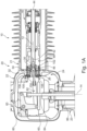
- Fig. 1A shows a high-voltage live tank circuit breaker 10 in a cross-section with the shown plane in parallel to a switching axis 12 and an operation axis 14.
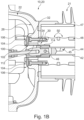
- Fig. 2B shows a detail of Fig. 1A .
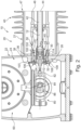
- Fig. 2 shows the circuit breaker 10 in a cross-section with the shown plane in parallel to the switching axis and perpendicular to the operation axis 14.
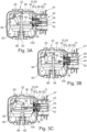
- Fig. 3A-C show the circuit breaker 10 in different states, wherein the breaker 10 is closed in Fig. 3A , is semi-open in Fig. 3B and is open in Fig. 3C .
- Fig. 4 shows another embodiment of a circuit breaker 10 with a first 21 and a third 23 housing member in line with each other which will be referred to later on.
- the circuit breaker 10 as shown in Fig. 1A comprises a housing structure 20 configured to be filled with a fluid, especially a dielectric gas like SF6 gas, an interrupter 40 arranged in the housing structure 20, and at least one apparatus 60, 80 configured to mechanically and electrically interact with the interrupter 40 and coupled to the interrupter 40 and at least partially arranged in a second housing member 22 of the housing structure 20.
- the circuit breaker 10 comprises an electrical apparatus 60 in the form of a current transformer arranged in the housing structure 20 and electrically coupled to the interrupter 40, and a drive apparatus 80 arranged in the housing structure 20 and mechanically coupled to the interrupter 40.
- the housing structure 20 has three housing members 21, 22, 23, particularly a first housing member 21, the second housing member 22 and a third housing member 23.
- the second housing member 22 is arranged between the first 21 and the third 23 housing member.
- the first 21 and the third 23 housing members are arranged oblique, e.g. substantially perpendicular, to one another with respect to their directions of elongation. Particularly, said directions of elongation extend along the axes 12 or 14, respectively.
- the housing structure 20 has a passage 30 which is configured for guiding the fluid between the first housing member 21 and the second housing member 22.
- the passage 30 has an end section 32 arranged in/within the first housing member 21.
- the passage 30 is limited by means of a substantially cylindrical bore in the second housing member 22.
- the electrical apparatus 60 and the drive apparatus 80 are at least partially arranged in the second housing member 22.
- the interrupter 40 is at least partially arranged in the first housing member 22.
- the passage 30 is formed between the first 21 and the second 22 housing member and points along the switching axis 12.
- the end section 32 of the passage 30 faces away from and/or past the at least one apparatus 60, 80, namely the electrical apparatus 60 and the drive apparatus 80.
- the interrupter 40 has a movable coupling member 42 and a movable contact member (not shown), wherein the coupling member 42 extends along and substantially in parallel to the first housing member 21.
- the coupling member 42 is mechanically coupled or fixed to the movable contact member.
- the movable coupling member 42 extends through the passage 30.
- the coupling member 42 is hollow and has a conduit 44 for guiding the fluid.
- the coupling member 42 furthermore has radial openings 45 in fluid connection to the conduit 44 for the fluid.
- the movable coupling member 42 is mechanically coupled via a joint 46 to the drive apparatus 80.
- the drive apparatus 80 essentially relates to a drive mechanism acting like a gear or gearbox.
- the drive apparatus 80 may have a motor, an actuator and/or an especially spring-based mechanical energy storage (not shown), particularly which is/are mechanically coupled to an insulating switching rod 84.
- the drive apparatus 80 has a conrod 82, a gear element 83 and an/the insulating switching rod 84 to which the movable coupling member 42 is mechanically coupled.
- the insulating switching rod 84 is coupled indirectly to the movable contact member 42.
- the insulating switching rod 84 is movable along the operation axis 14 and is arranged oblique to the movable coupling member 42, which coupling member is movable along the switching axis 12.
- the gear element 83 is pivotably and/or rotatably mounted inside the second housing member 22. Moving the rod 84 will pivot the gear element 83 and thereby move the conrod 82 and the movable coupling member 42.
- the first housing member 21 extends axially along the switching axis 12.
- the first housing member 21 is attached via an annular mounting face 36 to another annular mounting face 38 of the second housing member 22.
- the mounting faces 36, 38 are provided with an annular gasket.
- the first housing member 21 has an exhaust member 48 and a hull or cover member 47 surrounding the exhaust member 48.
- the hull or cover member 47 has fins on the outside facing radially outwards.
- the hull or cover member 47 is built electrically insulated at least on the outside.
- the hull or cover member 47 and the exhaust member 48 are attached to the second housing member 22.
- the exhaust member 48 surrounds, supports and guides the movable contact member 42.
- the exhaust member 48 is configured for guiding the fluid.
- the exhaust member 48 comprises openings 50 for letting fluid in or out.
- the exhaust member 48 is made from steel.
- the exhaust member 48 is attached to the second housing member 22 particularly to form the further end section 32 of the passage 30 sectionally.
- the at least one apparatus 60, 80 namely the electrical apparatus 60 and the drive apparatus 80, is/are arranged at one axial end 24 of the first housing member 21.
- the circuit breaker has a deflection structure 100 configured for a deflection of the fluid guided through the passage 30.
- the deflection structure 100 is arranged in and fastened, particularly bolted, to the housing structure 20 and is made of a metal alloy, particularly steel.
- the deflection structure 100 is arranged substantially in the passage 30 and at least in some switching positions or states surrounds the movable coupling member 42.
- the deflection structure 100 has, particularly is made from, a first deflection element 102 and a second deflection element 104.
- the first deflection element 102 has a substantially cylindrical shape.
- a gasket 110 is provided and configured to seal between the movable coupling member 42 and the first deflection element 102.
- the gasket 110 is attached to the movable coupling member 42.
- the gasket 110 runs on a cylindrical inside surface 112 of the first deflection element 102.
- the first deflection element 102 forms a further end section 34 of the passage 30, wherein the further end section 34 leads to the end section 32 and faces towards the interrupter 40.
- the further end section 34 is arranged radially outside of the first deflection element 102 and surrounds the movable coupling member 42.
- a cylindrical outside surface 114 of the first deflection element 102 forms with a/the cylindrical bore in the second housing element 22 and/or with the exhaust member 48 the further end section 34 of the passage 30.
- the second deflection element 104 forms the end section 32.
- the second deflection element 104 has a substantially annular shape and is arranged oblique to the movable coupling member 42 and the first deflection element 102.
- the second deflection element 104 has at least two radially extending portions 106, 108 of which a first radially extending portion 106 forms a first gap 107 in the end section 32 and a second radially extending portion 108 forms a second gap 109 in the end section 32, wherein the first gap 107 is smaller than the second gap 109.
- the second gap 109 thus is meant as a primary path for the dielectric fluid coming through the passage 30 into the second housing member 22.
- the deflection structure 100 namely the second deflection element 104, forms the end section 32 together with an inner surface 26 of the housing structure 20, namely of the second housing member 22.
- the inner surface 26 faces towards the at least one electrical apparatus 60, 80, particularly the electrical apparatus 60 and the drive apparatus 80, and away from the first housing member 21 and the interrupter 40.
- the fluid is guided not directly towards any one of the at least one apparatus 60, 80, particularly the electric apparatus 60 and/or the drive apparatus 80, but rather towards sides inside the housing structure 20 allowing for the fluid to cool down.
- the deflection structure 100 is fastened, particularly bolted, to the housing structure 20, namely to the second housing member 22, particularly to the exhaust member 48.
- the drive apparatus 80 comprises the insulating switching rod 84 and a grounded shield tube 86 surrounding the insulating switching rod 84.
- the insulating switching rod 84 is arranged in the grounded shield tube 86.
- the insulating switching rod 84 is mechanically coupled to the interrupter 40 through a drive mechanism including the conrod 82.
- the drive mechanism enabled that the insulating switching rod 84 is arranged perpendicular to the movable contact member 42.
- the circuit breaker 10 is shown in different states, namely a closed state (A), an open state (C) and a state in between closed and open states, namely semi-open state (B).
- a closed state A
- an open state C
- a state in between closed and open states namely semi-open state (B).
- the closed state the movable contact member is in electrical contact to the other contact member (not shown).
- the coupling member 42 In the closed state, the coupling member 42 is fully inserted into the first housing member 21 for making the contact members to contact one another.
- the insulating switching rod 84 is partially inserted into the second housing member 22, wherein a gear element 83 pivotably mounted inside the housing structure 20 is arranged to push in the conrod 82 which is coupled via the joint 46 to the movable coupling member 42.
- the movable coupling member 42 In the open state, the movable coupling member 42 is partially retracted from the first housing member 21 to disconnecting the contact members.
- the insulating switching rod 84 is partially retracted from the second housing member 22, wherein the gear element 83 has pivoted relative to the closed state in a clockwise direction in order to pull out the movable contact member via the conrod 84.
- the semi-open state illustrates a state between open and closed states wherein the directions of movement of each component elucidates. Furthermore, it becomes clear that the present invention provides that the fluid coming from the first housing member 21 guided into the second housing member 22 is not going directly onto the electrical apparatus 60 or the drive apparatus 80 - independent from the state the circuit breaker 10 assumes.
- the insulating switching rod 84 is mechanically coupled to the interrupter 40 directly in that the movement of the insulating switching rod 84 is proportionately and without a gear mechanism in between coupled to the interrupter 40.
- the insulating switching rod 84 is arranged in line with the movable contact member 42.
- the third housing member 23 is arranged substantially in line with the first housing member 21.
- the second housing member 22 is arranged between the first 21 and the third 23 housing member.
- the first 21 and the third 23 housing members are arranged line line with one another, e.g. substantially coaxially and/or in parallel, with respect to their directions of elongation. Particularly, said directions of elongation extend along the axes 12 or 14, respectively.
Landscapes
- Driving Mechanisms And Operating Circuits Of Arc-Extinguishing High-Tension Switches (AREA)
Abstract
a housing structure (20) configured to be filled with a fluid, having at least two housing members (21, 22, 23) including a first (21) and a second (22) housing member, and having a passage (30), the passage (30) configured for guiding a fluid between the first (21) and the second (22) housing member and having an end section (32) arranged within the second housing member (22);
an interrupter (40) arranged in the first housing member (21); and
at least one apparatus (60, 80) configured to interact with the interrupter and at least partially arranged in the second housing member (22), particularly wherein the at least one apparatus (60, 80) comprises an electrical apparatus (60) electrically coupled to the interrupter (40) and/or a drive apparatus (80) mechanically coupled to the interrupter (40);
wherein the end section (32) faces away from and/or past the at least one apparatus (60, 80).

Description
- The invention relates to a circuit breaker, especially a high-voltage live tank circuit breaker. The circuit breaker comprises a housing structure configured to contain a fluid. The circuit breaker further comprises, at least partially arranged in the housing structure, an interrupter and at least one apparatus, wherein the at least one apparatus is configured to interact with the interrupter.
- Typically, the housing structure is configured to contain or is filled with a fluid, especially a gas, including but not limited to a dielectric gas and/or air, surrounding the interrupter. When the interrupter is actuated or switched, an electric arc may be formed providing a heat source heating up the inside of the housing structure and typically the fluid. Heated up fluid and/or debris may be carried through the housing structure and possibly arrive at the at least one apparatus.
- It is of interest to provide enhancement with regard to handling the heat, heated up fluid and debris originating from a switching operation, especially from electric arcs inside the housing structure, to enhance or reduce in cost maintenance tasks, to increase lifetime of a breaker and to provide sufficient safety against failure of the breaker.
- It is therefore an object of the invention to provide solutions with respect to circuit breakers that provide an enhanced maintenance, reduced cost and increased lifetime. Particularly it is an object to avoid or reduce disadvantages of known solutions.
- The object of the invention is solved by the features of the independent claims. Preferred implementations are detailed in the dependent claims, the description and the figures.
- The object is particularly solved by a high-voltage live tank circuit breaker, comprising
- a housing structure configured to be filled with a fluid, the housing structure having at least two housing members including a first and a second housing member and having a passage, the passage configured for guiding the fluid between the first and the second housing member, and the housing structure having an end section arranged within the second housing member;
- an interrupter arranged in the first housing member; and
- at least one apparatus configured to, especially mechanically and/or electrically, interact with the interrupter and at least partially arranged in the second housing member, particularly the at least one apparatus comprising an electrical apparatus electrically coupled to the interrupter and/or a drive apparatus mechanically coupled to the interrupter;
- wherein the end section faces away from and/or past the at least one apparatus, particularly at least one of the electrical apparatus and the drive apparatus.
- Thus, the object is particularly solved by a high-voltage live tank circuit breaker comprising a housing structure having at least two housing members including a first housing member and a second housing member, and an interrupter arranged in the first housing member. Furthermore, one or more of a unit configured to work in combination with the interrupter, especially an electrical apparatus and/or a drive apparatus, is/are provided at least partially arranged in the second housing member. The unit particularly is electrically and/or mechanically coupled to the interrupter. It is proposed that the housing structure has and/or forms a passage, wherein the passage is configured for guiding a fluid between the first housing member and the second housing member. The passage has an end section particularly at least partially arranged within the second housing member. For particularly enhancing the lifetime of the circuit breaker it is suggested that the end section faces away from and/or faces past, particularly does not face, does not point towards and/or points beyond, at least one component of the unit or the entire unit.
- In other words, particularly, the present invention suggests a circuit breaker of a high-voltage and live tank type which has a housing comprising at least two housing parts, wherein a duct is formed guiding an electrically isolating fluid between the two housing parts, wherein an interrupter is at least partially arranged in one housing part, and wherein the duct has an end in the other housing part in which at least one of an electrical and/or mechanical and/or electro-mechanical apparatus, especially either a drive means, or an electrical means, or both, is/are arranged at least partially or sectionally or in their entirety. The end of the duct should not point towards, or at least substantially not towards, at least one of the apparatus, e.g. the drive means and the electrical means, typically which is/are located in the second housing member. This significantly reduces or avoids hot fluid being guided thereto and enhances lifetime of the breaker.
- By means of the invention and by means of aspects described in the present application, it is advantageously realized that hot fluid or dielectric gas is not directed towards the drive apparatus or towards the electrical apparatus. Rather, the hot fluid or dielectric gas is avoided to hit said apparatus or device when hot. An elongated path for the gas to travel reduces its temperature and/or speed so that fewer debris may reach said apparatus or device. Thus, functionality can be ensured for a longer time and/or maintenance effort is reduced. It may particularly be provided that the passage, particularly the end section, faces towards a bottom in the housing structure, more particularly a bottom of the second housing member.
- High or medium voltage devices, such as circuit breakers and switchgears are essential for the protection of technical equipment, especially in the high voltage range. For example, circuit breakers are predominantly used for interrupting a current, when an electrical fault occurs. As an example, circuit breakers have the task of opening arcing contacts, quench an arc, and keeping the arcing contacts apart from one another in order to avoid a current flow even in case of high electrical potential originating from the electrical fault itself. Circuit breakers may break medium to high short circuit currents of typically 1 kA to 80 kA at medium to high voltages of 12 kV to 72 kV and up to 1200 kV. Thus, high or medium voltage devices accommodate high-voltage conductors such as conductors to which a high voltage is applied.
- The component of a circuit breaker or switchgear designed to make or break the current is called interrupter or interrupter unit. During the service life of an/the electrical apparatus electrically coupled to the interrupter, such as a high or medium voltage device, the interrupter is subject to wear, in particular due to the electric arc that builds between the arcing contacts when breaking current. An electric arc is made up by a flux of electrons and a flux of ions which circulate in opposite directions between the arcing contacts. The wear of the interrupter accumulates during arcing and may change the operational characteristics of the interrupter and/or of the electrical apparatus. The interrupter may have two or more contacts or contact members, of which at least one is movable in order to switch or actuate the interrupter.
- The circuit breaker may be moved between an open position and a closed position, wherein in the open position an electrical connection is established and in the closed position and electrical connection is decoupled.
- The interrupter is preferably an interrupter for an electrical apparatus, such as a gas-insulated high or medium voltage device. The electrical apparatus is preferably configured as a current transformer or voltage transformer and/or configured for current or voltage transformation. The electrical apparatus may be at least partially housed or arranged in the circuit breaker, especially at least partially arranged in the housing structure, particularly the first and/or second housing member. Thus, the electrical apparatus - if present - is typically coupled to the interrupter, particularly electrically and/or mechanically.
- The term high voltage means preferably a voltage above 12 kV or 36 kV or 72 kV or 1100 kV. A high voltage preferably relates to nominal voltages in the range from above 12 kV, 36 kV or 72 kV to 550 kV or 1100 kV, like 145 kV, 245 kV or 420 kV, or even more.
- The at least one apparatus can interact with the interrupter. For example, the at least one apparatus may mechanically interact with the interrupter, e.g. in that the at least one apparatus assists in switching the interrupter. For example, the at least one apparatus may electrically interact with the interrupter, e.g. in that the at least one apparatus can be switched on and off by means of the interrupter. Interaction is particularly meant in the sense that components cooperate and/or depend on each other. As another example, the at least one apparatus is meant as one or more auxiliary unit(s) assisting the interrupter and/or cooperating with the interrupter with respect to functions of the circuit breaker.
- According to the suggested solution, the housing structure has at least two housing members including the first housing member and the second housing member. The housing structure may comprise more than two housing members, for example three or four or more. The (at least two) housing members may be attached to one another especially to form an inside of the housing structure. The housing members may be arranged and/or attached to one another in a row, for example wherein the first housing member is attached to the second housing member, and for example wherein the second is attached to the third housing member.
- At least one, more than one or all of the housing members may be at least partially or sectionally hollow. Typically, the housing structure is at least partially or sectionally hollow. The housing members may comprise mounting faces, especially wherein mounting faces of two housing members correspond to each other so that the housing structure can be sealed at the mounting faces so that the housing structure is at least substantially fluid tight, at least in the region of the mounting faces. The mounting faces may comprise an annular shape, ring shape and/or flat shape. The mounting faces may surround the passage. The mounting face may constitute and/or be arranged in a transition between the first and the second housing members or another housing member. The mounting face may hold a gasket.
- Typically, the at least one of the housing members, for example the first and/or the third, has an at least substantially elongated shape. The respective, especially the first, housing member may extend along a switching axis, wherein the switching axis substantially represents the direction along which the interrupter may be switched. Other housing members, for example the second and/or third housing member, may be shaped similarly as the first housing member. Two or more housing members may be arranged in line or may be arranged oblique or perpendicular to one another.
- Any one of the housing members may be made of more than one parts. For example, first housing member may comprise a hull or cover member and/or an exhaust member. The hull or cover member may form the shell of the first housing member and may be formed at least partially or sectionally electrically insulating. The exhaust member may form a duct for the fluid and/or a support for the interrupter, especially for the movable coupling member.
- The housing structure may be understood as a rigid structural component and/or housing of the circuit breaker. The housing structure may serve to house and/or be filled with the fluid, especially dielectric gas. The housing structure may be shaped to at least substantially hold the fluid and other components inside. The housing structure may serve to encase the interrupter, the electrical apparatus, the drive apparatus, and further components particularly supporting the function of the circuit breaker.
- The passage is meant or configured to guide the fluid, particularly the dielectric gas. Thus, an inner surface may form a duct or the like in order to provide the passage. The passage could comprise a bore or a hole or a duct. The passage may be understood as a section formed in the housing structure. The passage may be formed in a transition between the first and the second housing member or another housing member. The passage may be formed from at least one section including the end section and particularly a further end section opposite the end section. Particularly, said end sections may form start or end of the passage for the fluid to enter or leave the passage. There may be more than one passage, for example a plurality of passages like two, three or more. If there is a plurality of passages, the passages may be arranged next to each other and/or substantially in parallel to one another and/or may each end with one end section in the first housing member and/or may each end with another end section in the second housing member.
- The drive apparatus is typically understood as a means configured for switching or assisting in switching the interrupter, for example including but not limited to a gearbox, a gear, meshing gears, a lever mechanism, a motor, an actuator and/or an energy storage. In a basic configuration, the drive apparatus is merely a mechanical converter between a motor and the interrupter. It may be that the drive apparatus is a passive component of the circuit breaker which cannot move the interrupter without external energy input, and/or it may be that the drive apparatus is an active component which can actively move the interrupter.
- "Facing away" or "face away" in the context of the end section facing away from the electrical apparatus or the drive apparatus typically refers to the orientation or positioning of an object/section in such a way that a specific surface or side is directed or oriented to not point towards a reference point, or in this case the corresponding device or apparatus. "Facing away" or "face away" particularly denotes the spatial arrangement of an object or component where one of its surfaces, typically an end or side, is oriented in the opposite direction from a designated point of reference or a device. This positioning implies that the object's relevant surface is not directed towards or in close proximity to the device, emphasizing a state of disengagement or non-alignment, particularly so that fluid or dielectric gas guided through the passage would not be directed towards the electrical apparatus and/or the drive apparatus. The end section may be oriented away from the electrical apparatus and/or the drive apparatus.
- Further advantageous implementations of the invention are given as follows. The features named in the implementations may be individually combined with each other or considered alone.
- The interrupter may comprise a movable coupling member and a movable contact member. The movable coupling member may be provided for mechanical access to the movable contact member. The movable contact member may be the component directly subject to the electrical arc during interruption or actuation or the interrupter. The coupling member may extend along and/or substantially in parallel to the first housing member, especially with the first housing member having a substantially elongated shape. The coupling member may be mechanically coupled to the movable contact member, for example attached thereto. The movable coupling member may extend at least partially into and/or through the passage, especially for the fluid or dielectric gas to pass past the movable coupling member and away from the movable contact member.
- The circuit breaker, particularly the first housing member, may have an/the exhaust member. The exhaust member may surround, support and/or guide the movable contact member. The exhaust member may be configured for guiding the fluid. The exhaust member may comprise one or more openings for letting fluid in or out. The exhaust member may be made from a metal alloy. The exhaust member may be attached to the second housing member particularly to form a/the further end section of the passage at least sectionally.
- The coupling member may have a conduit for guiding the fluid. The coupling member may comprise a tube shape and/or hollow shape. The coupling member may serve as an exhaust passage for the fluid. For example, the arc may be arranged in the vicinity of one end of the conduit and the passage may be arranged in the vicinity of another end of the conduit for the conduit to guide fluid heated by the arc. The coupling member may have at least one or more than one radial opening(s) for guiding the fluid from the conduit towards the passage. This makes the circuit breaker more compact.
- The movable coupling member may be mechanically coupled, particularly via a joint, to the drive apparatus. The drive apparatus may comprise a conrod and/or an insulating switching rod to which the movable coupling member is mechanically coupled. The insulating switching rod may be arranged oblique to or substantially in line with and/or coaxial to and/or parallel to the movable coupling member. For example, the insulating switching rod may be coupled directly to the coupling member, preferably via the joint to balance out stresses. For example, the insulating switching rod may be coupled via the conrod to the coupling member to particularly enable insulating switching rod and coupling member to be arranged oblique to one another, preferably also including the joint to balance out stresses and/or to enable pivoting of the conrod. Particularly, the insulating switching rod may be substantially in line with and/or parallel to the coupling member. Alternatively, particularly, the insulating switching rod may be substantially perpendicular to and/or oblique to the coupling member. Particularly, the insulating switching rod may be configured to move the coupling member upon a movement, especially a translational and/or rotational movement, of the insulating switching rod. The insulating switching rod may be arranged at least sectionally in the second housing member and/or in a third housing member. This makes the circuit breaker more compact and flexible with respect to different applications.
- The first housing member may extends axially, especially along the switching axis. The first housing member may have a tube shape or pipe shape. The first housing member may comprise a/the hull or cover member on the outside and/or between axial ends of the first housing member. The first housing member may have fins or ribs facing radially outside. This decreases likeliness for short circuits from environmental influences, e.g. humidity or the like. This may also enhance convective cooling from ambient air.
- Inside the first housing member, particularly inside the hull or cover member, an exhaust member may be provided. Inside the exhaust member, the movable coupling member may be provided. The hull or cover member and/or the exhaust member may be attached to the second housing member.
- The electrical apparatus and/or the drive apparatus may be arranged at one axial end of the first housing member. The one axial end of the first housing member may have a substantially annular shape and/or may be open to form the passage. The second housing member is particularly attached, e.g. bolted, to the one axial end of the first housing member and/or an/the hull or cover member and/or an/the exhaust member for the end section to be formed in the first housing member. The first and second housing member may be coupled in a fluid tight manner for avoiding leakage of fluid from the housing structure and/or from the passage. Thus, the circuit breaker is more compact and more robust.
- A deflection structure may be provided. The circuit breaker may comprise the deflection structure. The deflection structure is particularly configured for at least sectionally forming the passage and/or for guiding the fluid. In some embodiments, the deflection structure may partially or fully comprise or form the passage. The deflection structure is particularly formed as a structural unit arranged in and/or coupled to the housing structure.
- The deflection structure is particularly configured for a deflection of the fluid, particularly the fluid guided through the passage. The deflection structure may be arranged in and/or fastened to the housing structure. For example, the deflection structure may be arranged in the first housing member, in the second housing member, or in the first and the second housing member. The deflection structure may be arranged in a transition between at least any two housing members, especially the first and second housing member. The deflection structure may at least sectionally form the passage and/or may be at least sectionally arranged in the passage.
- The deflection structure may comprise or consist of a metal alloy, for example including iron and/or aluminum, particularly steel. To provide sufficient structural integrity, metal alloys have been proven as a suitable material. The housing structure, particularly at least one or all of the housing members, may comprise or consist of a metal alloy and/or may be produced by metal casting. This provides stability and capability for conducting both electricity and heat. Particularly, iron or steel (iron alloy including carbon), aluminum alloy are materials of choice for best properties and a long service life.
- The deflection structure may be at least sectionally or partially arranged in the passage and/or surrounds the movable coupling member. For example, the movable coupling member may be arranged to point towards the second housing member and/or the passage, and/or may be arranged in the transition between two housing members, and particularly the movable coupling member may be arranged to point through the deflection structure. Again, this provides a compact circuit breaker with enhanced properties due to the deflection structure.
- The deflection structure may have a first deflection element e.g. with a substantially cylindrical shape and/or (preferably substantially cylindrical) inside and/or outside surface(s). The first deflection element may be arranged to surround the movable coupling member and/or the movable contact member. The circuit breaker may have a gasket, particularly the gasket configured to seal on the movable coupling member and/or the movable contact member relative to the deflection structure, especially the first deflection element, particularly the inside surface, e.g. so that the fluid coming from the arc and particularly through the conduit primarily is guided through a/the outside surface of the deflection structure and is not or substantially not guided through a/the inside surface of the first deflection element. The outside surface may face the housing structure and thus form the passage. The gasket may have an annular shape and/or may comprise or consist of a polymer compound and/or plastic material, preferably a thermoplastic, e.g. Polytetrafluoroethylene (PTFE for short). The gasket may be attached to the movable coupling member, e.g. by means of an annular ring and/or radial bolts, especially the radial bolts fixing via the ring the gasket to the movable coupling member.
- The first deflection element may form a further end section of the passage. Typically, the further end section leads to the end section and particularly faces towards the interrupter. It may be that the end section and the further end section form the entire passage. The further end section may be arranged radially outside of the first deflection element and/or may surround the movable coupling member. The (preferably substantially cylindrical) outside surface of the first deflection element may form a radial inside of the further end section. A radial outside of the further end section may be formed by means of the first and/or the second housing member(s) and/or the exhaust member. The further end section may comprise a substantially cylindrical shape and/or may be arranged in an axial direction, e.g. in parallel to and/or coaxial to the movable coupling member and/or the movable contact member.
- The deflection structure may have a second deflection element forming the end section. The second deflection element may be arranged and/or pointing in a substantially radial direction, especially in or inside the second housing member. The deflection elements may be attached to one another and/or may be formed from one piece of material and/or may be monolithically formed. The second deflection element may be arranged to form the end section. The end section may be arranged axially next to the second deflection element and/or may surround the movable coupling member and/or the movable contact member and/or the insulating switching rod. An axial face of the second deflection element may form one axial side of the end section. Another axial side of the end section may be formed by means of the second and/or the second housing member(s), particularly by an/the inner surface. The end section may comprise a substantially annular and/or collar shape and/or may be arranged in a radial direction, e.g. in oblique to and/or perpendicular to the movable coupling member and/or the movable contact member and/or the insulating switching rod. In a cross section, the deflection structure may have an L-shape.
- The second deflection element may have a substantially annular shape and/or is arranged oblique to the movable coupling member and/or the movable contact member and/or the first deflection element. The second deflection element may have a flange shape particularly in order to form the end section.
- The second deflection element may have at least two radially extending portions including a first radially extending portion and a second radially extending portion. The first radially extending portion may form a first gap particularly in the end section. The second radially extending portion may form a second gap particularly in end section. The first gap is preferably smaller than the second gap. Particularly, the first gap is oriented upwards and the second gap is oriented downwards. The first and second gap may be oriented in different radial directions. The first gap may be substantially zero to stop the fluid and/or to provide that the majority or all of the fluid goes past another or the second gap. For example, a gap may be formed due to the second deflection element comprising a bent section. The gap may be formed on one side by means of the second deflection element and on the opposite side by means of the second housing member.
- The deflection structure, particularly the second deflection element, may form the end section together with an/the inner surface of the housing structure, in particular of the second housing member. The second deflection element and the inner surface may together delimit the end section at least sectionally or fully. The inner surface may face towards the electrical apparatus and/or the drive apparatus. Alternatively or additionally, the inner surface may face away from the first housing member and/or the interrupter and/or the movable coupling member and/or the movable contact member. The inner surface may be arranged oblique to the movable coupling member and/or the movable contact member. The inner surface may at least sectionally delimit an inside of the second housing member. The inner surface may be formed by the second housing member, e.g. may be a cast surface and/or may be a metallic surface.
- The deflection structure, particularly the second deflection element, may be fastened, particularly bolted, to the housing structure, particularly to the second housing member and/or to the hull or cover member and/or to the exhaust member. At least one bolt or two or more bolts may be arranged substantially axially, especially projecting for fastening into the first and/or second housing member and/or into the exhaust member.
- According to another solution suggested by the invention, a deflection structure is suggested that is configured to be used in a housing structure of a high-voltage live tank circuit breaker, the housing structure configured to be filled with a fluid, wherein the circuit breaker comprises at least partially arranged inside the housing structure an interrupter and at least one apparatus configured to interact with the interrupter, wherein
- the deflection structure comprises of a metal alloy, a substantially cylindrical first deflection element and a particularly substantially annular second deflection element, particularly wherein the first and second deflection elements are attached to each other to form a structural unit, and particularly
- the deflection structure is configured to form a passage in the housing structure for the fluid and/or is configured to deflect the fluid away from and/or past the at least one apparatus.
- Thus, the deflection structure and/or a use of the deflection structure is provided particularly independent or separately from an entire circuit breaker. The deflection structure as described herein may be used in a housing structure of a high-voltage live tank circuit breaker to form a passage for a fluid and/or to deflect the fluid in the housing structure. Particularly, the suggested use of the deflection structure in a housing structure of a high-voltage live tank circuit breaker which housing structure is configured to be filled with a fluid includes that the circuit breaker comprises at least partially arranged inside the housing structure an interrupter and at least one apparatus configured to interact with the interrupter, wherein the deflection structure is used in the housing structure to form a passage for the fluid and/or to deflect the fluid away from and/or past the at least one apparatus. The invention may as well relate to the deflection structure on its own comprising any one of the features as described herein. Thus, existing circuit breakers may be retrofitted for enhancement.
- The drive apparatus may comprise an/the insulating switching rod and particularly a grounded shield tube. The insulating switching rod may be arranged in the grounded shield tube and/or in a third housing member of the housing structure, particularly the third housing member attached to the second housing member. The insulating switching rod is preferably mechanically coupled to the interrupter, for example either directly or through a mechanism or drive mechanism or gear.
- The circuit breaker may be filled with a fluid, especially a dielectric gas or insulating gas. Sulphur hexa-fluoride (SF6) is typically used as the fluid. Recently, the use of organofluorine compounds in a dielectric gas has been suggested as a substitute for SF6, such as for example a fluoroketone having high insulation capabilities, in particular a high dielectric strength, as well as high arc extinction capabilities. At the same time, they have a very low Global Warming Potential (GWP) and very low toxicity.
- An arrangement of two or three circuit breakers as described herein may be provided in order to break two or three different phases of an electrical line.
- The term 'or' may be replaced by 'and/or' throughout the present disclosure. As such, where 'or' is used, it is not necessarily meant that merely alternatives are named.
- These and other aspects of the invention will be apparent from and elucidated with reference to the implementations described hereinafter.
- In the drawings:
-
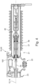
Fig. 1A-B shows a schematic cross-section of a circuit breaker with a housing structure, an interrupter, an electrical apparatus and a drive apparatus, -
Fig. 2 shows another schematic cross-section of the circuit breaker ofFig. 1 ; -
Fig. 3A-C shows a schematic cross-section of the circuit breaker ofFig. 1 with the interrupter in a closed state (A), between the closed state and an open state (B) and in the open state (C); and -
Fig. 4 shows a schematic cross-section of a circuit breaker of a further embodiment. - The description contains procedural or methodical aspects upon describing structural features of the invention; the structural features can be understood well in that way. It is emphasized to the reader that such structural features can be lifted from the described context without hesitation or the question of an intermediate generalization to form aspects of the invention. It is also emphasized to the reader that any the structural features described in the following can be understood as individual aspects of the invention to distinguish from known solutions, despite being possibly lifted from the context.
-
Fig. 1A shows a high-voltage livetank circuit breaker 10 in a cross-section with the shown plane in parallel to a switchingaxis 12 and anoperation axis 14. Fig. 2B shows a detail ofFig. 1A .Fig. 2 shows thecircuit breaker 10 in a cross-section with the shown plane in parallel to the switching axis and perpendicular to theoperation axis 14.Fig. 3A-C show thecircuit breaker 10 in different states, wherein thebreaker 10 is closed inFig. 3A , is semi-open inFig. 3B and is open inFig. 3C . -
Fig. 4 shows another embodiment of acircuit breaker 10 with a first 21 and a third 23 housing member in line with each other which will be referred to later on. - The
circuit breaker 10 as shown inFig. 1A comprises ahousing structure 20 configured to be filled with a fluid, especially a dielectric gas like SF6 gas, aninterrupter 40 arranged in thehousing structure 20, and at least oneapparatus interrupter 40 and coupled to theinterrupter 40 and at least partially arranged in asecond housing member 22 of thehousing structure 20. Particularly, thecircuit breaker 10 comprises anelectrical apparatus 60 in the form of a current transformer arranged in thehousing structure 20 and electrically coupled to theinterrupter 40, and adrive apparatus 80 arranged in thehousing structure 20 and mechanically coupled to theinterrupter 40. - The
housing structure 20 has threehousing members first housing member 21, thesecond housing member 22 and athird housing member 23. Thesecond housing member 22 is arranged between the first 21 and the third 23 housing member. The first 21 and the third 23 housing members are arranged oblique, e.g. substantially perpendicular, to one another with respect to their directions of elongation. Particularly, said directions of elongation extend along theaxes - The
housing structure 20 has apassage 30 which is configured for guiding the fluid between thefirst housing member 21 and thesecond housing member 22. Thepassage 30 has anend section 32 arranged in/within thefirst housing member 21. - In a radial outside direction with respect to the switching
axis 12, thepassage 30 is limited by means of a substantially cylindrical bore in thesecond housing member 22. - The
electrical apparatus 60 and thedrive apparatus 80 are at least partially arranged in thesecond housing member 22. Theinterrupter 40 is at least partially arranged in thefirst housing member 22. Thepassage 30 is formed between the first 21 and the second 22 housing member and points along the switchingaxis 12. - The
end section 32 of thepassage 30 faces away from and/or past the at least oneapparatus electrical apparatus 60 and thedrive apparatus 80. - The
interrupter 40 has amovable coupling member 42 and a movable contact member (not shown), wherein thecoupling member 42 extends along and substantially in parallel to thefirst housing member 21. Thecoupling member 42 is mechanically coupled or fixed to the movable contact member. Themovable coupling member 42 extends through thepassage 30. - The
coupling member 42 is hollow and has aconduit 44 for guiding the fluid. Thecoupling member 42 furthermore hasradial openings 45 in fluid connection to theconduit 44 for the fluid. - The
movable coupling member 42 is mechanically coupled via a joint 46 to thedrive apparatus 80. Thedrive apparatus 80 essentially relates to a drive mechanism acting like a gear or gearbox. Optionally, thedrive apparatus 80 may have a motor, an actuator and/or an especially spring-based mechanical energy storage (not shown), particularly which is/are mechanically coupled to an insulatingswitching rod 84. - The
drive apparatus 80 has aconrod 82, agear element 83 and an/the insulatingswitching rod 84 to which themovable coupling member 42 is mechanically coupled. Thus, the insulatingswitching rod 84 is coupled indirectly to themovable contact member 42. - The insulating
switching rod 84 is movable along theoperation axis 14 and is arranged oblique to themovable coupling member 42, which coupling member is movable along the switchingaxis 12. Thegear element 83 is pivotably and/or rotatably mounted inside thesecond housing member 22. Moving therod 84 will pivot thegear element 83 and thereby move theconrod 82 and themovable coupling member 42. - The
first housing member 21 extends axially along the switchingaxis 12. Thefirst housing member 21 is attached via an annular mountingface 36 to another annular mountingface 38 of thesecond housing member 22. The mounting faces 36, 38 are provided with an annular gasket. - The
first housing member 21 has anexhaust member 48 and a hull or covermember 47 surrounding theexhaust member 48. The hull or covermember 47 has fins on the outside facing radially outwards. The hull or covermember 47 is built electrically insulated at least on the outside. - The hull or cover
member 47 and theexhaust member 48 are attached to thesecond housing member 22. Theexhaust member 48 surrounds, supports and guides themovable contact member 42. Theexhaust member 48 is configured for guiding the fluid. Theexhaust member 48 comprisesopenings 50 for letting fluid in or out. Theexhaust member 48 is made from steel. Theexhaust member 48 is attached to thesecond housing member 22 particularly to form thefurther end section 32 of thepassage 30 sectionally. - The at least one
apparatus electrical apparatus 60 and thedrive apparatus 80, is/are arranged at oneaxial end 24 of thefirst housing member 21. - The circuit breaker has a
deflection structure 100 configured for a deflection of the fluid guided through thepassage 30. Thedeflection structure 100 is arranged in and fastened, particularly bolted, to thehousing structure 20 and is made of a metal alloy, particularly steel. - The
deflection structure 100 is arranged substantially in thepassage 30 and at least in some switching positions or states surrounds themovable coupling member 42. - The
deflection structure 100 has, particularly is made from, afirst deflection element 102 and asecond deflection element 104. Thefirst deflection element 102 has a substantially cylindrical shape. - A
gasket 110 is provided and configured to seal between themovable coupling member 42 and thefirst deflection element 102. Thegasket 110 is attached to themovable coupling member 42. Thegasket 110 runs on a cylindrical insidesurface 112 of thefirst deflection element 102. - The
first deflection element 102 forms afurther end section 34 of thepassage 30, wherein thefurther end section 34 leads to theend section 32 and faces towards theinterrupter 40. Thefurther end section 34 is arranged radially outside of thefirst deflection element 102 and surrounds themovable coupling member 42. - A cylindrical
outside surface 114 of thefirst deflection element 102 forms with a/the cylindrical bore in thesecond housing element 22 and/or with theexhaust member 48 thefurther end section 34 of thepassage 30. - The
second deflection element 104 forms theend section 32. Thesecond deflection element 104 has a substantially annular shape and is arranged oblique to themovable coupling member 42 and thefirst deflection element 102. - The
second deflection element 104 has at least two radially extendingportions radially extending portion 106 forms afirst gap 107 in theend section 32 and a secondradially extending portion 108 forms asecond gap 109 in theend section 32, wherein thefirst gap 107 is smaller than thesecond gap 109. Thesecond gap 109 thus is meant as a primary path for the dielectric fluid coming through thepassage 30 into thesecond housing member 22. - The
deflection structure 100, namely thesecond deflection element 104, forms theend section 32 together with aninner surface 26 of thehousing structure 20, namely of thesecond housing member 22. Theinner surface 26 faces towards the at least oneelectrical apparatus electrical apparatus 60 and thedrive apparatus 80, and away from thefirst housing member 21 and theinterrupter 40. - Due to the
deflection structure 100, the fluid is guided not directly towards any one of the at least oneapparatus electric apparatus 60 and/or thedrive apparatus 80, but rather towards sides inside thehousing structure 20 allowing for the fluid to cool down. - The
deflection structure 100 is fastened, particularly bolted, to thehousing structure 20, namely to thesecond housing member 22, particularly to theexhaust member 48. - Presently, the
drive apparatus 80 comprises the insulatingswitching rod 84 and a groundedshield tube 86 surrounding the insulatingswitching rod 84. Thus, the insulatingswitching rod 84 is arranged in the groundedshield tube 86. Here, the insulatingswitching rod 84 is mechanically coupled to theinterrupter 40 through a drive mechanism including theconrod 82. The drive mechanism enabled that the insulatingswitching rod 84 is arranged perpendicular to themovable contact member 42. - With reference to
Figs. 3A-C , thecircuit breaker 10 is shown in different states, namely a closed state (A), an open state (C) and a state in between closed and open states, namely semi-open state (B). In the closed state the movable contact member is in electrical contact to the other contact member (not shown). - In the closed state, the
coupling member 42 is fully inserted into thefirst housing member 21 for making the contact members to contact one another. Here, the insulatingswitching rod 84 is partially inserted into thesecond housing member 22, wherein agear element 83 pivotably mounted inside thehousing structure 20 is arranged to push in theconrod 82 which is coupled via the joint 46 to themovable coupling member 42. - In the open state, the
movable coupling member 42 is partially retracted from thefirst housing member 21 to disconnecting the contact members. The insulatingswitching rod 84 is partially retracted from thesecond housing member 22, wherein thegear element 83 has pivoted relative to the closed state in a clockwise direction in order to pull out the movable contact member via theconrod 84. - The semi-open state illustrates a state between open and closed states wherein the directions of movement of each component elucidates. Furthermore, it becomes clear that the present invention provides that the fluid coming from the
first housing member 21 guided into thesecond housing member 22 is not going directly onto theelectrical apparatus 60 or the drive apparatus 80 - independent from the state thecircuit breaker 10 assumes. - With reference to the embodiment shown in
Fig. 4 , the insulatingswitching rod 84 is mechanically coupled to theinterrupter 40 directly in that the movement of the insulatingswitching rod 84 is proportionately and without a gear mechanism in between coupled to theinterrupter 40. Particularly, the insulatingswitching rod 84 is arranged in line with themovable contact member 42. Thethird housing member 23 is arranged substantially in line with thefirst housing member 21. - With further reference to
Fig. 4 , thesecond housing member 22 is arranged between the first 21 and the third 23 housing member. The first 21 and the third 23 housing members are arranged line line with one another, e.g. substantially coaxially and/or in parallel, with respect to their directions of elongation. Particularly, said directions of elongation extend along theaxes -
- 10
- breaker
- 12
- switching axis
- 14
- operation axis
- 20
- housing structure
- 21
- first housing member
- 22
- second housing member
- 23
- third housing member
- 24
- axial end
- 26
- inner surface
- 30
- passage
- 32
- end section
- 34
- further end section
- 36
- mounting face
- 38
- mounting face
- 40
- interrupter
- 42
- coupling member
- 44
- conduit
- 45
- opening
- 46
- joint
- 47
- hull or cover member
- 48
- exhaust member
- 50
- opening
- 60
- electrical apparatus
- 80
- drive apparatus
- 82
- conrod
- 83
- gear element
- 84
- insulating switching rod
- 86
- grounded shield tube
- 100
- deflection structure
- 102
- first deflection element
- 104
- second deflection element
- 106
- radially extending portion
- 107
- gap
- 108
- radially extending portion
- 109
- gap
- 110
- gasket
- 112
- inside surface
- 114
- outside surface
Claims (15)
- High-voltage live tank circuit breaker (10), comprisinga housing structure (20) configured to be filled with a fluid, having at least two housing members (21, 22, 23) including a first (21) and a second (22) housing member, and having a passage (30), the passage (30) configured for guiding a fluid between the first (21) and the second (22) housing member and having an end section (32) arranged within the second housing member (22);an interrupter (40) arranged in the first housing member (21); andat least one apparatus (60, 80) configured to interact with the interrupter and at least partially arranged in the second housing member (22), particularly wherein the at least one apparatus (60, 80) comprises an electrical apparatus (60) electrically coupled to the interrupter (40) and/or a drive apparatus (80) mechanically coupled to the interrupter (40);wherein the end section (32) faces away from and/or past the at least one apparatus (60, 80).
- Breaker (10) according to the preceding claim, the interrupter (40) comprising a movable coupling member (42) and a movable contact member, wherein the coupling member (42) extends along and/or substantially in parallel to the first housing member (21) and is mechanically coupled to the movable contact member, particularly wherein the movable coupling member (42) extends through the passage (30).
- Breaker (10) according to the preceding claim, wherein the coupling member (42) has a conduit (44) for guiding the fluid.
- Breaker (10) according to any one of the preceding two claims, wherein the movable coupling member (42) is mechanically coupled, particularly via a joint (46), to the drive apparatus (80), particularly wherein the drive apparatus (80) comprises a conrod (82) and/or an insulating switching rod (84) to which the movable coupling member (42) is mechanically coupled, particularly the insulating switching rod (84) arranged oblique to or substantially in line with the movable coupling member (42).
- Breaker (10) according to any one of the preceding claims, wherein the first housing member (21) extends axially and wherein the at least one apparatus, especially an electrical apparatus (60) and/or a drive apparatus (80), are arranged at one axial end (24) of the first housing member (21).
- Breaker (10) according to any one of the preceding claims, comprising a deflection structure (100) configured for a deflection of the fluid guided through the passage (30), particularly arranged in and/or fastened to the housing structure (20) and/or particularly comprising or consisting of a metal alloy.
- Breaker (10) according to the preceding claim, wherein the deflection structure (100) is at least sectionally arranged in the passage (30) and/or surrounds the movable coupling member (42).
- Breaker (10) according to any one of the preceding two claims, wherein the deflection structure (100) has a first deflection element (102) with a substantially cylindrical shape and particularly with a gasket (110) configured to seal on the movable coupling member (42).
- Breaker (10) according to the preceding claim, wherein the first deflection element (102) forms a further end section (34) of the passage (30), wherein the further end section (34) leads to the end section (32) and particularly faces towards the interrupter (40), particularly the further end section (34) arranged radially outside of the first deflection element (102) and/or surrounding the movable coupling member (42).
- Breaker (10) according to any one of the preceding four claims, wherein the deflection structure (100) has a second deflection element (104) forming the end section (32).
- Breaker (10) according to any one of the preceding claim, wherein the second deflection element (104) has a substantially annular shape and/or is arranged oblique to the movable coupling member (42) and/or the first deflection element (102).
- Breaker (10) according to any one of the preceding two claims, wherein the second deflection element (104) has at least two radially extending portions (106, 108) of whicha first radially extending portion (106) forms a first gap (107) in the end section (32) anda second radially extending portion (108) forms a second gap (109) in end section (32), wherein the first gap (107) is smaller than the second gap (109).
- Breaker (10) according to any one of the preceding seven claims, whereinthe deflection structure (100), particularly the second deflection element (104), forms the end section (32) together with an inner surface (26) of the housing structure (20), in particular of the second housing member (22), particularly the inner surface (26) facing towards the at least one apparatus (60, 80), and/or away from the first housing member (21) and/or the interrupter (40); and/orthe deflection structure (100), particularly the second deflection element (102), is fastened, particularly bolted, to the housing structure (20), particularly to the second housing member (22).
- Breaker (10) according to any one of the preceding claims, wherein the drive apparatus (80) comprises an/the insulating switching rod (84) and particularly a grounded shield tube (86), particularly the insulating switching rod (84) arranged in the grounded shield tube (86) and/or in a third housing member (23) of the housing structure (20), which insulating switching rod (84) is mechanically coupled to the interrupter (40) either directly or through a drive mechanism.
- Deflection structure (100) configured to be used in a housing structure (20) of a high-voltage live tank circuit breaker (10), the housing structure (20) configured to be filled with a fluid, wherein the circuit breaker (10) comprises at least partially arranged inside the housing structure (20) an interrupter (40) and at least one apparatus (60, 80) configured to interact with the interrupter (40), whereinthe deflection structure (100) comprises a metal alloy, a substantially cylindrical first deflection element (102) and a particularly substantially annular second deflection element (104), andthe deflection structure (100) is configured to form a passage (30) in the housing structure (20) for the fluid and/or is configured to deflect the fluid away from and/or past the at least one apparatus (60, 80).
Priority Applications (1)
| Application Number | Priority Date | Filing Date | Title |
|---|---|---|---|
| EP23200498.6A EP4531069A1 (en) | 2023-09-28 | 2023-09-28 | Circuit breaker |
Applications Claiming Priority (1)
| Application Number | Priority Date | Filing Date | Title |
|---|---|---|---|
| EP23200498.6A EP4531069A1 (en) | 2023-09-28 | 2023-09-28 | Circuit breaker |
Publications (1)
| Publication Number | Publication Date |
|---|---|
| EP4531069A1 true EP4531069A1 (en) | 2025-04-02 |
Family
ID=88236715
Family Applications (1)
| Application Number | Title | Priority Date | Filing Date |
|---|---|---|---|
| EP23200498.6A Pending EP4531069A1 (en) | 2023-09-28 | 2023-09-28 | Circuit breaker |
Country Status (1)
| Country | Link |
|---|---|
| EP (1) | EP4531069A1 (en) |
Citations (5)
| Publication number | Priority date | Publication date | Assignee | Title |
|---|---|---|---|---|
| US4500762A (en) * | 1982-03-25 | 1985-02-19 | Mitsubishi Denki Kabushiki Kaisha | Resistor-type disconnecting switch for circuit breaker |
| JPH06119852A (en) * | 1992-10-01 | 1994-04-28 | Mitsubishi Electric Corp | Gas-insulated ground switchgear |
| US5850065A (en) * | 1996-02-22 | 1998-12-15 | Hitachi, Ltd. | Gas circuit breaker |
| DE102012209307A1 (en) * | 2012-06-01 | 2013-12-05 | Siemens Aktiengesellschaft | Compressed gas-insulated electric power transmission unit, has active conductors retained in receiving space of housing that is supported at supporting insulator, where receiving spaces of housing and insulator are separated from each other |
| FR3012690A1 (en) * | 2013-10-30 | 2015-05-01 | Alstom Technology Ltd | MODULE FOR PSEM |
-
2023
- 2023-09-28 EP EP23200498.6A patent/EP4531069A1/en active Pending
Patent Citations (5)
| Publication number | Priority date | Publication date | Assignee | Title |
|---|---|---|---|---|
| US4500762A (en) * | 1982-03-25 | 1985-02-19 | Mitsubishi Denki Kabushiki Kaisha | Resistor-type disconnecting switch for circuit breaker |
| JPH06119852A (en) * | 1992-10-01 | 1994-04-28 | Mitsubishi Electric Corp | Gas-insulated ground switchgear |
| US5850065A (en) * | 1996-02-22 | 1998-12-15 | Hitachi, Ltd. | Gas circuit breaker |
| DE102012209307A1 (en) * | 2012-06-01 | 2013-12-05 | Siemens Aktiengesellschaft | Compressed gas-insulated electric power transmission unit, has active conductors retained in receiving space of housing that is supported at supporting insulator, where receiving spaces of housing and insulator are separated from each other |
| FR3012690A1 (en) * | 2013-10-30 | 2015-05-01 | Alstom Technology Ltd | MODULE FOR PSEM |
Similar Documents
| Publication | Publication Date | Title |
|---|---|---|
| US10553377B2 (en) | Arrangement and method for guiding a switch rod of a high-voltage circuit breaker | |
| US6927355B2 (en) | Circuit breaker | |
| JP7118992B2 (en) | vacuum switch | |
| CN101465236A (en) | Vacuum insulated switchgear | |
| EP1152444B1 (en) | Switch gear | |
| KR101919125B1 (en) | Gas insulated switch device of high voltage distributer | |
| KR100474173B1 (en) | Insulated Switchgear | |
| US11348748B2 (en) | Switch device | |
| US5625179A (en) | Isolator for a metal-encapsulated, gas-insulated, high-voltage switching installation | |
| KR101246696B1 (en) | Ground disconnect switch and method for making same | |
| US3794799A (en) | Gas insulated switch with adjustable overcenter toggle actuator therefore | |
| US4301341A (en) | Electrical switchgear | |
| EP0011972A2 (en) | Electrical switchgear | |
| KR100374239B1 (en) | Switch gear | |
| US3582589A (en) | Fluid-blast circuit interrupter with piston assembly and electromagnetic driving means | |
| KR20210047623A (en) | Vacuum interrupter and vacuum circuit breaker having the same | |
| EP1320860B1 (en) | Circuit breaker | |
| CA2189322A1 (en) | Electrical switching device | |
| US20240313512A1 (en) | Switchgear architecture | |
| EP4459653B1 (en) | A switching apparatus for electrical systems | |
| EP4738409A1 (en) | Switchgear, method and use | |
| EP4345858A1 (en) | A switch, a load break switch and a switchgear | |
| JP2009129855A (en) | Vacuum circuit breaker | |
| GB2044538A (en) | Electrical switchgear | |
| CA2410703A1 (en) | Combination of a vacuum interruption device and oil-filled transformer |
Legal Events
| Date | Code | Title | Description |
|---|---|---|---|
| PUAI | Public reference made under article 153(3) epc to a published international application that has entered the european phase |
Free format text: ORIGINAL CODE: 0009012 |
|
| STAA | Information on the status of an ep patent application or granted ep patent |
Free format text: STATUS: THE APPLICATION HAS BEEN PUBLISHED |
|
| AK | Designated contracting states |
Kind code of ref document: A1 Designated state(s): AL AT BE BG CH CY CZ DE DK EE ES FI FR GB GR HR HU IE IS IT LI LT LU LV MC ME MK MT NL NO PL PT RO RS SE SI SK SM TR |
|
| STAA | Information on the status of an ep patent application or granted ep patent |
Free format text: STATUS: REQUEST FOR EXAMINATION WAS MADE |
|
| 17P | Request for examination filed |
Effective date: 20251002 |
|
| STAA | Information on the status of an ep patent application or granted ep patent |
Free format text: STATUS: EXAMINATION IS IN PROGRESS |
|
| 17Q | First examination report despatched |
Effective date: 20260130 |