EP4530992A1 - Mehrere beleuchtungsbedingungen für biometrische authentifizierung - Google Patents
Mehrere beleuchtungsbedingungen für biometrische authentifizierung Download PDFInfo
- Publication number
- EP4530992A1 EP4530992A1 EP24201173.2A EP24201173A EP4530992A1 EP 4530992 A1 EP4530992 A1 EP 4530992A1 EP 24201173 A EP24201173 A EP 24201173A EP 4530992 A1 EP4530992 A1 EP 4530992A1
- Authority
- EP
- European Patent Office
- Prior art keywords
- images
- illumination
- light
- illumination channels
- biometric
- Prior art date
- Legal status (The legal status is an assumption and is not a legal conclusion. Google has not performed a legal analysis and makes no representation as to the accuracy of the status listed.)
- Pending
Links
Images




Classifications
-
- G—PHYSICS
- G06—COMPUTING OR CALCULATING; COUNTING
- G06F—ELECTRIC DIGITAL DATA PROCESSING
- G06F21/00—Security arrangements for protecting computers, components thereof, programs or data against unauthorised activity
- G06F21/30—Authentication, i.e. establishing the identity or authorisation of security principals
- G06F21/31—User authentication
- G06F21/32—User authentication using biometric data, e.g. fingerprints, iris scans or voiceprints
-
- G—PHYSICS
- G06—COMPUTING OR CALCULATING; COUNTING
- G06V—IMAGE OR VIDEO RECOGNITION OR UNDERSTANDING
- G06V10/00—Arrangements for image or video recognition or understanding
- G06V10/10—Image acquisition
- G06V10/12—Details of acquisition arrangements; Constructional details thereof
- G06V10/14—Optical characteristics of the device performing the acquisition or on the illumination arrangements
- G06V10/141—Control of illumination
-
- G—PHYSICS
- G06—COMPUTING OR CALCULATING; COUNTING
- G06V—IMAGE OR VIDEO RECOGNITION OR UNDERSTANDING
- G06V10/00—Arrangements for image or video recognition or understanding
- G06V10/10—Image acquisition
- G06V10/12—Details of acquisition arrangements; Constructional details thereof
- G06V10/14—Optical characteristics of the device performing the acquisition or on the illumination arrangements
- G06V10/143—Sensing or illuminating at different wavelengths
-
- G—PHYSICS
- G06—COMPUTING OR CALCULATING; COUNTING
- G06V—IMAGE OR VIDEO RECOGNITION OR UNDERSTANDING
- G06V10/00—Arrangements for image or video recognition or understanding
- G06V10/10—Image acquisition
- G06V10/12—Details of acquisition arrangements; Constructional details thereof
- G06V10/14—Optical characteristics of the device performing the acquisition or on the illumination arrangements
- G06V10/145—Illumination specially adapted for pattern recognition, e.g. using gratings
-
- G—PHYSICS
- G06—COMPUTING OR CALCULATING; COUNTING
- G06V—IMAGE OR VIDEO RECOGNITION OR UNDERSTANDING
- G06V40/00—Recognition of biometric, human-related or animal-related patterns in image or video data
- G06V40/10—Human or animal bodies, e.g. vehicle occupants or pedestrians; Body parts, e.g. hands
- G06V40/16—Human faces, e.g. facial parts, sketches or expressions
- G06V40/172—Classification, e.g. identification
-
- G—PHYSICS
- G06—COMPUTING OR CALCULATING; COUNTING
- G06V—IMAGE OR VIDEO RECOGNITION OR UNDERSTANDING
- G06V40/00—Recognition of biometric, human-related or animal-related patterns in image or video data
- G06V40/10—Human or animal bodies, e.g. vehicle occupants or pedestrians; Body parts, e.g. hands
- G06V40/18—Eye characteristics, e.g. of the iris
-
- G—PHYSICS
- G06—COMPUTING OR CALCULATING; COUNTING
- G06V—IMAGE OR VIDEO RECOGNITION OR UNDERSTANDING
- G06V40/00—Recognition of biometric, human-related or animal-related patterns in image or video data
- G06V40/10—Human or animal bodies, e.g. vehicle occupants or pedestrians; Body parts, e.g. hands
- G06V40/18—Eye characteristics, e.g. of the iris
- G06V40/197—Matching; Classification
Definitions
- Biometric authentication technology uses one or more biometric aspects of a person to identify that person, for example for secure, authenticated access to devices, systems, etc.
- one or more images are captured of biometric aspects to be tracked (e.g., images of a person's iris(es) may be captured), and the images are processed to generate a set of metrics that are unique to, and thus uniquely identify, that person.
- images of the person's biometric aspects are again captured and processed using a similar algorithm to the one used during registration. Metrics determined from the data captured at the later time are compared to stored metrics from the registration and, if a match between the two is sufficiently good, the person is authenticated.
- Biometric authentication systems using multiple illumination channels to capture images of a biometric aspect may be able to derive more information than biometric authentication systems which do not use multiple illumination channels.
- the biometric authentication system may use the multiple illumination channels in a quality assurance algorithm, for example, to identify instances wherein a non-real representation of a biometric aspect is being presented in place of a real biometric aspect, such as a printout of a picture of an eye being presented instead of an actual person engaging with the system to have an image of the person's eye captured.
- the multiple illumination channels may provide additional information streams that may be used to increase a robustness of a biometric authentication process.
- images captured under different illumination conditions may be considered to be images of "different illumination channels.”
- a biometric aspect match such as an iris match
- the biometric authentication process may further evaluate matching properties of several versions of iris images captured with different illumination channels. This may increase the security of the biometric authentication process.
- an order in which illumination channels are applied may be tracked, or otherwise known by the biometric authentication process, and the biometric authentication process may verify not only an iris match, but also that the iris image illumination channel matches the illumination channel applied for a given image capture.
- using multiple illumination channels in a quality assurance algorithm may conserve computer resources by bypassing further processing of images that have a non-matching illumination channel property.
- a machine learning assisted quality assurance algorithm may be used to further reduce computer resources expended to identify matching and non-matching illumination channel properties.
- a machine learning model may be trained to generate inferences as to an illumination channel property of a given image, which can then be compared to a known illumination channel applied when capturing the given image.
- multiple illumination channels may be used to evaluate multiple types of biometric aspects, such as biometric aspects in the periocular region, and/or in the eye, such as the iris.
- images of a periocular region captured using multiple illumination channels may provide information about a three-dimensional (3D) structure of a periocular region.
- Other biometric aspects may include a face, an ear, and a hand.
- a biometric authentication system may use such information about 3D structures of biometric aspects to perform authentication or may use such information in combination with an iris-based biometric authentication process or another kind of authentication system.
- Configured To Various units, circuits, or other components may be described or claimed as “configured to” perform a task or tasks.
- “configured to” is used to connote structure by indicating that the units/circuits/components include structure (e.g., circuitry) that performs those task or tasks during operation.
- the unit/circuit/component can be said to be configured to perform the task even when the specified unit/circuit/component is not currently operational (e.g., is not on).
- the units/circuits/components used with the "configured to” language include hardware - for example, circuits, memory storing program instructions executable to implement the operation, etc.
- a unit/circuit/component is “configured to” perform one or more tasks is expressly intended not to invoke 35 U.S.C. ⁇ 112, paragraph (f), for that unit/circuit/component.
- "configured to” can include generic structure (e.g., generic circuitry) that is manipulated by software or firmware (e.g., an FPGA or a general-purpose processor executing software) to operate in manner that is capable of performing the task(s) at issue.
- "Configure to” may also include adapting a manufacturing process (e.g., a semiconductor fabrication facility) to fabricate devices (e.g., integrated circuits) that are adapted to implement or perform one or more tasks.
- Second “First,” “Second,” etc. As used herein, these terms are used as labels for nouns that they precede, and do not imply any type of ordering (e.g., spatial, temporal, logical, etc.).
- a buffer circuit may be described herein as performing write operations for "first” and “second” values.
- the terms “first” and “second” do not necessarily imply that the first value must be written before the second value.
- An illumination channel may correspond to a configuration of illumination elements used to capture an image of a biometric aspect, such as an iris of an eye or a periocular region surrounding the eye.
- Such configurations of the illumination elements may be varied across multiple image captures to produce a set of multiple illumination channel images of the same biometric aspect.
- images of the same iris may be captured under a set of varied illumination configurations to generate a set of multiple illumination channel images of the iris.
- Quality assurance using multiple illumination channels may identify attempts to satisfy biometric authentication without actually presenting an actual biometric aspect of a user, such as the periocular region of an enrolled user or an iris of an enrolled user.
- images captured using different illumination configurations comprise different illumination channels and thus provide a more robust dataset about a given biometric aspect than images captured using the same illumination configuration.
- a biometric authentication system may use additional information resulting from the multiple illumination channels to make a biometric authentication process more robust, such as by avoiding false positives and false negatives.
- a biometric authentication system may obtain information about a three-dimensional (3D) structure of a periocular region by capturing images using different illumination configurations. The information about the 3D structure and other qualities of the periocular region captured using the different illumination channels may be used to perform biometric authentication.
- a generated biometric template may be an enrollment template, and the enrollment template may be stored such that a processor may later compare the enrollment template to a subsequently received biometric input, which may be processed into a match template, associated with a request for authentication.
- Biometric authentication may include biometric identification of a user, for example, identifying one enrolled user from a set of enrolled users based on a comparison of a match template to enrollment templates corresponding to users of the set of users.
- a biometric authentication system may generate different illumination configurations, and corresponding different illumination channels, by varying the wavelengths, intensities, and/or directions of light being emitted by one or more illumination sources.
- the biometric authentication system may use different illumination channels in a quality assurance system that may include a trained machine learning model which checks that the illumination channel a captured image appears to have as an image property corresponds to a recorded, or otherwise known, illumination configuration that was used to capture the image.
- a biometric authentication system may determine, based on a non-match in this quality assurance system, that the captured image is not an image of a biometric aspect of an actual person that was presented to the sensor or otherwise has been faked or manipulated.
- resulting shadows in an image may indicate the illumination configuration used and thus the illumination channel property of that image. If another image is presented that was not captured using the same illumination configuration, the shadows in the other image may not match the expected illumination channel and thus the biometric authentication system may reject the captured image as a low-quality image (e.g., a faked image capture, etc.).
- multiple illumination channel images may increase entropy in a dataset used for biometric authentication and thus make the biometric authentication system more robust. For example, if two people have very similar biometric aspects that are difficult to distinguish (just as an example for purposes of illustration) a biometric authentication system may make a false positive authentication. To avoid this, a similarity score threshold used by the biometric authentication system may be set sufficiently high to avoid false positives. However, though the two people have similar biometric aspects, the biometric authentication system may use differences to distinguish between the two people. These differences may manifest themselves differently in images captured under different lighting conditions.
- the biometric authentication system capturing multiple images of a given biometric aspect under different lighting conditions results in the biometric authentication system having multiple illumination channel images, which provide more information about the biometric aspect and capture more differences (e.g., greater entropy).
- the biometric authentication system may adjust thresholds for determining an authentication to avoid both false positives and false negatives. In this way, a biometric authentication system using multiple illumination channel images can improve a robustness of the biometric authentication system.
- a biometric authentication system using multiple illumination channels may be included in devices such as mobile user devices (e.g., smartphones and smart watches), vehicles (e.g., automobiles), stationary devices (e.g., displays, televisions, doorbells, smart home control units, and smart speakers), and head-mounted display devices (e.g., headset-type display devices and glasses-type display devices).
- a biometric authentication system using multiple illumination channels may analyze biometric aspects such as an iris, a periocular region, a face, an ear, a hand, and other biometric aspects of a user.
- FIG. 1A is a front view of an illumination source with multiple independent light-emitting elements, according to some embodiments.
- FIG. 1A shows an example illumination source 110 that includes multiple light-emitting elements 102 and 104.
- the light-emitting elements may be light-emitting diodes (LEDs), and in some embodiments other light-emitting elements other than LEDs may be used, or a combination of LEDs and other light-emitting elements may be used.
- some of the light-emitting elements may be configured to emit light at a first wavelength and other light-emitting elements may be configured to emit light at a different wavelength.
- wavelengths may be used.
- individual light-emitting elements may be configured to selectively emit light at two or more different wavelengths.
- Individual light-emitting elements may also be configured to emit light at various intensities.
- FIG. 1B is a side view of an illumination source using an illumination configuration to generate an illumination channel, as well as a controller, a camera, and a biometric aspect, according to some embodiments.
- FIG. 1B illustrates an example imaging system that includes an illumination source, according to some embodiments.
- the imaging system may include, but is not limited to, one or more cameras 140, an illumination source 110, and a controller 160.
- the eye camera 140 is pointed towards the eye which is being used as a biometric aspect 150 to receive reflected light from the illumination source 110 that has been reflected off of the biometric aspect 150.
- the eye camera 140 may instead or also capture images of the periocular region and portions of the face.
- the controller 160 has sent an illumination configuration for a first illumination channel 120 to the illumination source 110, which caused one light-emitting element 102 to be activated.
- the camera 140 has captured an image of the biometric aspect 150 illuminated using the first illumination channel 122 and has sent the image to the controller 160.
- more than one camera may be used to capture images of the biometric aspect.
- a camera may be a visible light camera or a non-visible light camera, for example, an infrared or near-infrared camera.
- FIG. 1C is a side view of an illumination source using a different illumination configuration than the one in use in FIG. 1B , as well as a controller, a camera, and a biometric aspect, according to some embodiments.
- the controller 160 has selected a second illumination configuration for a second illumination channel 130 and has sent control instructions to the illumination source 110, causing a different light-emitting element 104 to be activated.
- the camera 140 has captured an image of the biometric aspect 150 illuminated using the second illumination channel 132 and has sent the image to the controller 160.
- the controller 160 may use the images captured at the different illumination configurations in a multiple illumination channel analysis system.
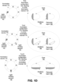
- FIG. 1D is a graphical representation of three illumination configurations and three illumination channels that may be generated by the respective illumination configurations, according to some embodiments.
- the top pair of images of FIG. 1D show the illumination source 110 at the first illumination configuration 120 that was shown in FIG. 1B , where light-emitting element 102 is active at a specific wavelength and intensity, and the first illumination channel 124 that resulted from the first illumination configuration 120.
- the illumination channel 124 of the periocular region 190 has shadows 194 around the area of the eyes 192 where there is a change in depth.
- the second pair of images shows a third illumination configuration 170 not seen in FIGs. 1B and 1C where two light-emitting elements 102 and 104 are active, and the third illumination channel 174 that results from this third illumination configuration 170. Because there is more than one light-emitting element 102 and 104 active, there are different shadows 196 caused by the depth change around the eyes 192. Illumination channels may comprise multiple active light-emitting elements which may be active at different wavelengths and intensities from each other.
- the third pair of images shows a fourth illumination configuration 180 where a light-emitting element 106 not previously used is active, and the fourth illumination channel 184 that results from the fourth illumination configuration 180. Because this is a different illumination channel 184, it has generated different shadows 198 than the shadows 194 and 196 that were generated by other illumination channels 124 and 174.
- the three shown illumination channels 124, 174, and 184 may be used in a quality assurance system and/or part of a biometric analysis system.
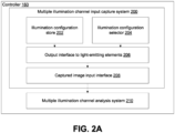
- FIG. 2A is a block diagram illustrating components of a multiple illumination channel input capture system that may be implemented by a controller used to capture images for evaluation by a multiple illumination channel analysis system, such as with regard to illumination channels applied when capturing the images, according to some embodiments.
- FIG. 2A shows possible components of a multiple illumination channel input capture system 200 that may be implemented via the controller 160.
- a multiple illumination channel input capture system 200 may be used to generate input using multiple illumination channels for use in a multiple illumination channel analysis system 210.
- the multiple illumination channel input capture system 200 may include an illumination configuration store 202 and an illumination configuration selector 204, both of which may communicate with an output interface to light-emitting elements 206 to send a selected illumination configuration to control the light-emitting elements.
- the multiple illumination channel input capture system 200 may also include a captured image input interface 208 to receive the images taken using selected illumination channels.
- the captured image input interface 208 may provide the captured images to a multiple illumination channel analysis system 210 which may use the captured images and the recorded, or otherwise known, order of the illumination configurations sent by the output interface to light-emitting elements 206.
- the multiple illumination channel analysis system 210 is further described in FIG. 2B .
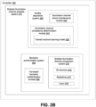
- FIG. 2B is a block diagram illustrating components of an example multiple illumination channel analysis system that may be implemented by a controller, according to some embodiments.
- FIG. 2B shows possible components of the multiple illumination channel analysis system 210 being implemented via the controller 160.
- the multiple illumination channel analysis system 210 may include a quality assurance system 220.
- the quality assurance system 220 may include an illumination channel record maintenance module 230 to record the illumination channels that images were taken at.
- There may also be an illumination channel consistency determination module 240 comprising a trained machine learning model 250.
- the illumination channel consistency determination module is expanded on in FIG. 4 .
- the multiple illumination channel analysis system 210 may also include a biometric authentication system 260.
- the biometric authentication system 260 may include a multiple illumination channel comparison system 270 comprising a module to analyze 3D structure 272, a module to analyze reflectivity 274, and a module to analyze color 276.
- the multiple illumination channel comparison system 270 may include one or more trained machine learning models to derive information from captured images.
- the multiple illumination channel comparison system 270 may compare information about a biometric aspect's 3D structure, reflectivity, and color in an image at an illumination channel to information about an enrolled user's biometric aspect's 3D structure, reflectivity, and color from a stored template generated from one or more images captured at the same illumination channel during enrollment.
- the use of multiple illumination channels in a single authentication process may increase certainty that the person is an enrolled user by increasing the number of chances for the multiple illumination channel comparison system to detect abnormalities, and increasing the difficulty of mimicking an enrolled user, by using illumination channels that result in dissimilar light interactions with the biometric aspect, such as a periocular region.
- the multiple illumination channel comparison system 270 may use a similarity scoring algorithm in this comparison to determine whether 3D structure, reflectivity, and color of the periocular region match 3D structure, reflectivity, and color of an enrolled user's periocular region.
- Various thresholds may be used, such as a similarity score indicating a match of greater than X% (e.g., 90%, 95%, 99%, etc.) is required to consider an image as a match to a stored image captured at the same illumination channel.
- the biometric authentication system 260 may require a threshold to be reached at one or more than one illumination channel.
- the biometric authentication system 260 may also include an iris-based biometric authentication process 280 which may interact with the multiple illumination channel comparison system 270 as shown in FIG. 5 .
- determining a 3D structure match may be a preceding or subsequent step to determining an iris match, as an example.
- an iris-based biometric authentication process may be a component of a multiple illumination channel comparison system 270 where images of an iris are compared to stored images of an iris captured at the same illumination channels.
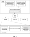
- FIG. 3 is a block diagram illustrating a remote training system that trains a machine learning model for use in a quality assurance system and a set of devices that use the trained machine learning model to evaluate illumination channels, according to some embodiments.
- a machine learning model is trained (310) in a training process 380 so that it may be used in a runtime evaluation process 390.
- the two training datasets 320 and 330 are sets of training data which may be used in some embodiments to create a trained machine learning model 250.
- Machine learning model training 310 may use one or more sets of training data.
- a set of training data comprising periocular region images labeled according to the illumination channels used to capture the images (320) may be used to train the machine learning model on what the illumination channels look like when they are applied to a periocular region.
- the training data may be information derived from images, for example, the training data may include 3D structure data, reflectivity, and the wavelengths of reflected light.
- a set of training data comprising images labeled according to whether they are valid images which can be used for authentication may be used to train the machine learning model that some images are not useful and may be ignored without the controller needing to calculate objective standards of image quality.
- Images that are valid may be images that are known to be images of a biometric aspect and have been captured at a known illumination configuration.
- Valid images may include information that may be used in a biometric authentication system.
- Invalid images may be images that are not of a biometric aspect and may include images of objects such as an image of an image of a periocular region, images with significant blurring or obstruction, and images captured at a non-informative illumination configuration, such as a complete absence of light.
- machine learning model training 310 may use more than one set of training data, or machine learning model training 310 may use a set of training data that uses a combination of labeling systems.
- the trained machine learning model 250 may be sent over a network 340 to various devices, such as devices 350, 352, and 354, and may be used in a runtime evaluation process 390 at the respective devices to determine illumination channel properties of images by analyzing images captured using varying illumination source configurations (360) and generating inferences, such as embedded features, about characteristics of the images' illumination channels 370.
- the generated inferences may be used by an illumination channel consistency determination module 240 as further described in FIG. 4 to decide whether the inferred illumination channels match the recorded illumination channels.
- FIG. 4 is a process flow diagram illustrating an example illumination channel consistency determination process, according to some embodiments.
- FIG. 4 shows an illumination channel consistency determination module 240 that is being implemented via a controller 160.
- a trained machine learning model trained on images which may be information derived from images, that are labeled according to the illumination channel used to capture them may estimate which illumination channel was used while images were being captured.
- the illumination channel consistency determination module 240 may compare the estimated illumination channel to a recorded, or otherwise known, illumination channel.
- the illumination channel consistency determination module 240 decides whether the variations in the images are consistent with the illumination channel as indicated by the recorded order, or order that is otherwise known by the illumination channel consistency module 240. In some embodiments, the illumination channel consistency determination module 240 may make such a decision by determining whether the percentage of correctly estimated illumination channels meets a threshold percentage.
- the illumination channel consistency determination module 240 may determine the images are of sufficient quality. For example, if images of the same biometric aspect are captured using five illumination channels and it is determined that four or more of the illumination channel properties of the image are a match with the recorded or otherwise known illumination channels used, then the set of images may pass the quality check. Though it should be understood that different numbers of illumination channels and different thresholds may be used in a quality check.
- the illumination channel consistency determination module 240 may determine the images are not of sufficient quality. In some embodiments, a determination that the images are not of sufficient quality may trigger additional authentication requirements.
- FIG. 5 is a process flow diagram illustrating a possible biometric authentication process that uses a 3D structure in combination with iris-based biometric authentication, according to some embodiments.
- the biometric authentication system 260 begins at 510 by causing an input image of the periocular region to be captured. The biometric authentication system 260 then decides at 512 whether there is an open eye in the image. If there is an open eye in the image, the biometric authentication system 260 may proceed to 280, an iris-based biometric authentication process. If there is not an open eye in the image, the biometric authentication system 260 may proceed to 270, a multiple illumination channel comparison system.
- a biometric authentication system may derive information about an image, for example whether the image includes an open eye, by using a trained machine learning model. A biometric authentication system may use one or more trained machine learning models to derive additional information from images, such as information indicating three-dimensional structure, reflectivity, and wavelengths of reflected light.
- a similarity scoring algorithm may be used to generate a match score.
- Various thresholds may be used, such as match score indicating a match of greater than X% (e.g., 90%, 95%, 99%, etc.) is required to determine a match is sufficiently "high” and a match score indicating a match of less than Y% (e.g., 90%, 85%, 80%, etc.) is required to determine a match is sufficiently “low.”
- X% may be higher than Y%.
- a similarity scoring algorithm may be used in both an iris-based biometric authentication process and a multiple illumination channel comparison system.
- a match score is generated in the iris-based authentication process by comparing information about an iris in the input image to stored information about a registered user's iris.
- the biometric authentication system 260 may authenticate 522.
- the match score is sufficiently low the biometric authentication system 260 may not authenticate. If the match score for the iris-based authentication process is not sufficiently high or low, the match score may be indeterminate and the biometric authentication system 260 may proceed to 270 a multiple illumination channel comparison system.
- a match score 514 is generated in the multiple illumination channel comparison system by comparing information derived from the input image such as periocular region 3D structure, reflectivity, and color to a stored multiple illumination channel template including information derived from an image labeled as corresponding to the illumination channel of the input image, such as periocular region 3D structure, reflectivity, and color.
- the match score is sufficiently high the biometric authentication system 260 may authenticate.
- the match score is sufficiently low the biometric authentication system 260 may not authenticate.
- the biometric authentication system 260 may retry by returning to 510 the image capture step.
- a multiple illumination channel comparison system may prevent a biometric authentication system 260 from failing due to lack of an open eye or an indeterminate iris match.
- the biometric authentication system 260 uses the iris-based authentication process 280 if possible, but note that some embodiments may conserve computer resources by using the multiple illumination channel comparison system 270 before or instead of the iris-based authentication process 280. In some embodiments, other types of authentication systems (e.g., such as a fingerprint-based authentication system) may be additionally used.
- FIGs. 6A-D illustrate examples of information about 3D structure and other biometric surface information that may be used by a multiple illumination channel analysis system, according to some embodiments.
- FIG. 6A depicts a portion of the periocular region (e.g., such as a nose) that has been divided into four planes 612, each of which has a surface normal 610 associated with it.
- Surface normals 610 are vectors normal to the plane of a surface 612.
- Surface normals 610 may be information about 3D structure that may be used in a biometric authentication system.
- surface normals may be generated by first dividing an image into sections and determining the surface normals of the sections or by finding the surface normals at some set frequency across the image.
- a biometric authentication system may use a trained machine learning model to determine surface normals, for example, by using one or more of shading information of an individual image and perspective from multiple images captured at different angles.
- a biometric authentication system may use surface normals as information indicating three-dimensional structure. Three-dimensional structure may include information about the size and shape of the biometric aspect.
- FIG. 6B depicts a contour map, which may represent 3D structure.
- This contour map has four depth ranges, 620, 622, 624, and 626.
- the outside of the contour map is uniformly in the second depth range 622. Moving inward from the outside edge, the depth increases to the deepest depth range, the first depth range 620. Moving further inward, the depth decreases to the second depth range 622 again, and then continues decreasing through the third depth range 624 to the highest depth range, the fourth depth range 626 in the center.
- a contour map such as this one may represent an approximation of 3D structure in a two-dimensional format.
- a biometric authentication system may use a trained machine learning model to determine a depth map, such as a contour map, as information derived from one or more images.
- a biometric authentication system may use a depth sensor to obtain depth information.
- a biometric authentication system may use a depth map as information indicating three-dimensional structure.
- FIG. 6C depicts emitted light 630 being reflected off of a surface 636 and becoming reflected light 632.
- emitted light 630 is reflected off of a surface 636
- some light may be absorbed 634, so the reflected light 632 may have a lower intensity than the emitted light 630.
- the change in intensity from emitted light 630 to reflected light 632 may allow calculation of the surface's 636 reflectivity.
- Some of the absorbed light 634 may be light of specific wavelengths, as shown in FIG. 6D .
- FIG. 6D also shows a change that may occur when light is reflected off a surface 636, focusing on the absorption 634 of some wavelengths of emitted light 630 by the surface 626 so that the reflected light 632 may not include some wavelengths or may partially include some wavelengths.
- the wavelengths of reflected light for a biometric authentication system may correspond to one or more of wavelengths in the visible spectrum and wavelengths not in the visible spectrum.
- the first wavelength 644A of emitted light 640 is unchanged 644B after interacting with the surface 636 and becoming reflected light 642.
- the second wavelength 646A was completely absorbed by the surface 636 and is not present among the wavelengths of reflected light 642.
- the third wavelength 648 was partially absorbed by the surface 636 and is less intense as reflected light 648B.
- illumination configurations may vary with regard to additional qualities of light, for example, illumination profiles.
- An illumination profile indicates the combination of position and intensity of one or more illumination elements, and therefore indicate the uniformity or the lack of uniformity of illumination intensity across a surface, for example, a biometric aspect.
- FIGs. 7A-C illustrate example devices that could be used to implement a multiple illumination channel analysis system, according to some embodiments.
- FIG. 7A illustrates an example head-mounted device (HMD) that may include components and implement methods as illustrated in FIGs. 1 through 6 , according to some embodiments.
- the HMD may be positioned on the user's head 790 such that the display is disposed in front of the user's eyes. The user looks through the eyepieces onto the display.
- FIGs. 7A-C illustrate example devices in which the methods of FIGs. 1 through 6 may be implemented, according to some embodiments.
- the devices 350 as illustrated in FIGs. 7A through 7C are given by way of example and are not intended to be limiting.
- the shape, size, and other features of an HMD may differ, as may the locations, numbers, types, and other features of the components of an HMD and of the eye imaging system.
- FIG. 7A shows a side view of an example HMD
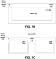
- FIGs. 7B and 7C show alternative front views of example HMDs, with FIG. 7B showing a device 350 that has one lens 730 that covers both eyes 740 and FIG. 7C showing a device 350 that has right 730A and left 730B lenses.
Landscapes
- Engineering & Computer Science (AREA)
- Theoretical Computer Science (AREA)
- Physics & Mathematics (AREA)
- General Physics & Mathematics (AREA)
- Multimedia (AREA)
- Human Computer Interaction (AREA)
- Health & Medical Sciences (AREA)
- General Health & Medical Sciences (AREA)
- Computer Security & Cryptography (AREA)
- Ophthalmology & Optometry (AREA)
- General Engineering & Computer Science (AREA)
- Computer Hardware Design (AREA)
- Software Systems (AREA)
- Computer Vision & Pattern Recognition (AREA)
- Artificial Intelligence (AREA)
- Oral & Maxillofacial Surgery (AREA)
- Image Input (AREA)
- Collating Specific Patterns (AREA)
- Measurement Of The Respiration, Hearing Ability, Form, And Blood Characteristics Of Living Organisms (AREA)
Applications Claiming Priority (2)
| Application Number | Priority Date | Filing Date | Title |
|---|---|---|---|
| US202363585681P | 2023-09-27 | 2023-09-27 | |
| US18/625,883 US20250103693A1 (en) | 2023-09-27 | 2024-04-03 | Multiple Illumination Conditions for Biometric Authentication |
Publications (1)
| Publication Number | Publication Date |
|---|---|
| EP4530992A1 true EP4530992A1 (de) | 2025-04-02 |
Family
ID=92843228
Family Applications (1)
| Application Number | Title | Priority Date | Filing Date |
|---|---|---|---|
| EP24201173.2A Pending EP4530992A1 (de) | 2023-09-27 | 2024-09-18 | Mehrere beleuchtungsbedingungen für biometrische authentifizierung |
Country Status (3)
| Country | Link |
|---|---|
| US (1) | US20250103693A1 (de) |
| EP (1) | EP4530992A1 (de) |
| CN (1) | CN119723006A (de) |
Citations (3)
| Publication number | Priority date | Publication date | Assignee | Title |
|---|---|---|---|---|
| US20180349721A1 (en) * | 2017-06-06 | 2018-12-06 | Microsoft Technology Licensing, Llc | Biometric object spoof detection based on image intensity variations |
| US20200311238A1 (en) * | 2017-12-13 | 2020-10-01 | Princeton Identity, Inc. | Systems and methods of multi-modal biometric analysis |
| US20210365533A1 (en) * | 2020-05-20 | 2021-11-25 | Facebook Technologies, Llc | Systems and methods for authenticating a user of a head-mounted display |
Family Cites Families (12)
| Publication number | Priority date | Publication date | Assignee | Title |
|---|---|---|---|---|
| CN100498837C (zh) * | 2004-05-10 | 2009-06-10 | 松下电器产业株式会社 | 虹彩注册方法、虹彩注册装置 |
| WO2008131201A1 (en) * | 2007-04-19 | 2008-10-30 | Global Rainmakers, Inc. | Method and system for biometric recognition |
| US8334900B2 (en) * | 2008-07-21 | 2012-12-18 | The Hong Kong University Of Science And Technology | Apparatus and method of optical imaging for medical diagnosis |
| US8254768B2 (en) * | 2010-12-22 | 2012-08-28 | Michael Braithwaite | System and method for illuminating and imaging the iris of a person |
| CN105093492B (zh) * | 2014-05-22 | 2018-06-26 | 宁波舜宇光电信息有限公司 | 一种摄像光学镜组及虹膜摄像模组 |
| EP3259734B1 (de) * | 2015-02-20 | 2024-07-24 | Seeing Machines Limited | Verminderung von blendung |
| JP2019506694A (ja) * | 2016-01-12 | 2019-03-07 | プリンストン・アイデンティティー・インコーポレーテッド | 生体測定分析のシステムおよび方法 |
| US11151235B2 (en) * | 2017-08-01 | 2021-10-19 | Apple Inc. | Biometric authentication techniques |
| CN109325394B (zh) * | 2017-08-01 | 2022-06-21 | 苹果公司 | 确定稀疏图案照明与密集图案照明 |
| US11200408B2 (en) * | 2017-11-28 | 2021-12-14 | Fingerprint Cards Anacatum Ip Ab | Biometric imaging system and method for controlling the system |
| US20200334478A1 (en) * | 2019-04-16 | 2020-10-22 | GM Global Technology Operations LLC | Occupant monitoring appartus and applications thereof |
| US12131585B2 (en) * | 2019-06-06 | 2024-10-29 | Nec Corporation | Processing system, processing method, and non-transitory storage medium |
-
2024
- 2024-04-03 US US18/625,883 patent/US20250103693A1/en active Pending
- 2024-09-18 EP EP24201173.2A patent/EP4530992A1/de active Pending
- 2024-09-19 CN CN202411303241.3A patent/CN119723006A/zh active Pending
Patent Citations (3)
| Publication number | Priority date | Publication date | Assignee | Title |
|---|---|---|---|---|
| US20180349721A1 (en) * | 2017-06-06 | 2018-12-06 | Microsoft Technology Licensing, Llc | Biometric object spoof detection based on image intensity variations |
| US20200311238A1 (en) * | 2017-12-13 | 2020-10-01 | Princeton Identity, Inc. | Systems and methods of multi-modal biometric analysis |
| US20210365533A1 (en) * | 2020-05-20 | 2021-11-25 | Facebook Technologies, Llc | Systems and methods for authenticating a user of a head-mounted display |
Also Published As
| Publication number | Publication date |
|---|---|
| US20250103693A1 (en) | 2025-03-27 |
| CN119723006A (zh) | 2025-03-28 |
Similar Documents
| Publication | Publication Date | Title |
|---|---|---|
| CN108664783B (zh) | 基于虹膜识别的识别方法和支持该方法的电子设备 | |
| US11151234B2 (en) | Augmented reality virtual reality touchless palm print identification | |
| US12462518B2 (en) | Flexible illumination for imaging systems | |
| US20170061647A1 (en) | Biometric Based Authentication for Head-Mountable Displays | |
| US20230377370A1 (en) | Multi-camera biometric imaging system | |
| CN110266916B (zh) | 用于在眼睛追踪中处理眩光的方法和系统 | |
| US20230367857A1 (en) | Pose optimization in biometric authentication systems | |
| US20230334909A1 (en) | Multi-wavelength biometric imaging system | |
| US10872402B2 (en) | Specular reflection reduction using polarized light sources | |
| US20230379564A1 (en) | Biometric authentication system | |
| US9934583B2 (en) | Expectation maximization to determine position of ambient glints | |
| EP4530992A1 (de) | Mehrere beleuchtungsbedingungen für biometrische authentifizierung | |
| CN118871822A (zh) | 包括透镜阵列的摄像头 | |
| EP4217920A1 (de) | Automatische auswahl von biometrik auf der basis der qualität eines erfassten bildes | |
| US20260016602A1 (en) | Frequency Modulated Continuous Wave Optical Authentication System | |
| TWI853329B (zh) | 具有立體影像處理功能的立體影像感測裝置及應用於其上之立體影像處理方法 | |
| US20260101115A1 (en) | Apparatus and method for controlling light sources for eye tracking | |
| WO2025186947A1 (ja) | 認証装置、車両、認証方法及び記録媒体 | |
| KR101424515B1 (ko) | 등록 얼굴 생성 장치 및 방법 |
Legal Events
| Date | Code | Title | Description |
|---|---|---|---|
| PUAI | Public reference made under article 153(3) epc to a published international application that has entered the european phase |
Free format text: ORIGINAL CODE: 0009012 |
|
| STAA | Information on the status of an ep patent application or granted ep patent |
Free format text: STATUS: REQUEST FOR EXAMINATION WAS MADE |
|
| 17P | Request for examination filed |
Effective date: 20240918 |
|
| AK | Designated contracting states |
Kind code of ref document: A1 Designated state(s): AL AT BE BG CH CY CZ DE DK EE ES FI FR GB GR HR HU IE IS IT LI LT LU LV MC ME MK MT NL NO PL PT RO RS SE SI SK SM TR |