EP4530736A1 - Developing device and image forming apparatus - Google Patents
Developing device and image forming apparatus Download PDFInfo
- Publication number
- EP4530736A1 EP4530736A1 EP24158571.0A EP24158571A EP4530736A1 EP 4530736 A1 EP4530736 A1 EP 4530736A1 EP 24158571 A EP24158571 A EP 24158571A EP 4530736 A1 EP4530736 A1 EP 4530736A1
- Authority
- EP
- European Patent Office
- Prior art keywords
- developer
- holder
- toner
- image
- developing
- Prior art date
- Legal status (The legal status is an assumption and is not a legal conclusion. Google has not performed a legal analysis and makes no representation as to the accuracy of the status listed.)
- Granted
Links
Images





Classifications
-
- G—PHYSICS
- G03—PHOTOGRAPHY; CINEMATOGRAPHY; ANALOGOUS TECHNIQUES USING WAVES OTHER THAN OPTICAL WAVES; ELECTROGRAPHY; HOLOGRAPHY
- G03G—ELECTROGRAPHY; ELECTROPHOTOGRAPHY; MAGNETOGRAPHY
- G03G15/00—Apparatus for electrographic processes using a charge pattern
- G03G15/06—Apparatus for electrographic processes using a charge pattern for developing
- G03G15/08—Apparatus for electrographic processes using a charge pattern for developing using a solid developer, e.g. powder developer
- G03G15/09—Apparatus for electrographic processes using a charge pattern for developing using a solid developer, e.g. powder developer using magnetic brush
- G03G15/0942—Apparatus for electrographic processes using a charge pattern for developing using a solid developer, e.g. powder developer using magnetic brush with means for preventing toner scattering from the magnetic brush, e.g. magnetic seals
-
- G—PHYSICS
- G03—PHOTOGRAPHY; CINEMATOGRAPHY; ANALOGOUS TECHNIQUES USING WAVES OTHER THAN OPTICAL WAVES; ELECTROGRAPHY; HOLOGRAPHY
- G03G—ELECTROGRAPHY; ELECTROPHOTOGRAPHY; MAGNETOGRAPHY
- G03G15/00—Apparatus for electrographic processes using a charge pattern
- G03G15/06—Apparatus for electrographic processes using a charge pattern for developing
- G03G15/08—Apparatus for electrographic processes using a charge pattern for developing using a solid developer, e.g. powder developer
- G03G15/09—Apparatus for electrographic processes using a charge pattern for developing using a solid developer, e.g. powder developer using magnetic brush
- G03G15/0921—Details concerning the magnetic brush roller structure, e.g. magnet configuration
-
- G—PHYSICS
- G03—PHOTOGRAPHY; CINEMATOGRAPHY; ANALOGOUS TECHNIQUES USING WAVES OTHER THAN OPTICAL WAVES; ELECTROGRAPHY; HOLOGRAPHY
- G03G—ELECTROGRAPHY; ELECTROPHOTOGRAPHY; MAGNETOGRAPHY
- G03G15/00—Apparatus for electrographic processes using a charge pattern
- G03G15/06—Apparatus for electrographic processes using a charge pattern for developing
- G03G15/08—Apparatus for electrographic processes using a charge pattern for developing using a solid developer, e.g. powder developer
- G03G15/0806—Apparatus for electrographic processes using a charge pattern for developing using a solid developer, e.g. powder developer on a donor element, e.g. belt, roller
- G03G15/081—Apparatus for electrographic processes using a charge pattern for developing using a solid developer, e.g. powder developer on a donor element, e.g. belt, roller characterised by the developer handling means after the supply and before the regulating, e.g. means for preventing developer blocking
-
- G—PHYSICS
- G03—PHOTOGRAPHY; CINEMATOGRAPHY; ANALOGOUS TECHNIQUES USING WAVES OTHER THAN OPTICAL WAVES; ELECTROGRAPHY; HOLOGRAPHY
- G03G—ELECTROGRAPHY; ELECTROPHOTOGRAPHY; MAGNETOGRAPHY
- G03G15/00—Apparatus for electrographic processes using a charge pattern
- G03G15/06—Apparatus for electrographic processes using a charge pattern for developing
- G03G15/08—Apparatus for electrographic processes using a charge pattern for developing using a solid developer, e.g. powder developer
- G03G15/0896—Arrangements or disposition of the complete developer unit or parts thereof not provided for by groups G03G15/08 - G03G15/0894
- G03G15/0898—Arrangements or disposition of the complete developer unit or parts thereof not provided for by groups G03G15/08 - G03G15/0894 for preventing toner scattering during operation, e.g. seals
Definitions
- the present invention relates to a developing device and an image forming apparatus.
- JP1994-11970A discloses a developing apparatus of an image forming apparatus that includes a development magnetic pole; and at least one conveyance magnetic pole arranged on the downstream side of the development magnetic pole, in which, using a developer carrier in which the polarity of the conveyance magnetic pole adjacent to the development magnetic pole is different from the polarity of the development magnetic pole, a magnetic brush of a two-component developer containing toner and carrier as main components is formed on the developer carrier to develop an electrostatic latent image formed on a photoreceptor, a member for collecting the carrier separated from the developer carrier is provided close to the conveyance magnetic pole adjacent to the development magnetic pole, and a magnetic pole having the identical polarity as the development magnetic pole is provided inside the carrier collecting member.
- An object of the present invention is to efficiently collect the floating toner in the developing device as compared with a case where an electric field is provided that collects the normal electrode toner but does not collect the reverse polarity toner.
- a developing device including a developer holder that holds a developer containing toner and carrier and being supplied to an image holder forming an electrostatic latent image; a first member that is provided on a downstream side of a developing position that is a position where the developer held by the developer holder is supplied to the image holder; and a second member that is provided between the developer holder, the image holder, and the first member, that has a surface facing the developer holder, and to which an intermediate potential as a potential between a potential applied to the developer holder and a potential applied to the first member is applied.
- the developing device in which the developer holder may have a magnet for forming a brush containing the carrier of the developer, toward a center direction of the first member.
- the developing device in which the magnet may be adjacent to different polarity magnets, which have magnetic poles different from the magnet and are arranged on an upstream side and a downstream side of the magnet in the developer holder.
- the developing device in which in a case where reverse polarity toner drawn to the second member is collected by the developer that comes into contact with the first member on the downstream side of the position where the developer of the developer holder is supplied, the developer may come into contact with the first member in a range in which, among brushes, each of the brushes on the upstream side and the downstream side has a predetermined angle with respect to the center direction.
- the developing device in which the intermediate potential of the second member may be set such that, among a distance between the second member and the developer holder and a distance between the second member and the first member, a potential difference of the shorter distance is smaller than a potential difference of the far distance.
- the developing device in which the setting may be performed according to a ratio of the distance between the second member and the developer holder and the distance between the second member and the first member.
- the developing device according to any one of the first aspect to the sixth aspect, in which the second member may have a polygonal shape having the surface as a slope.
- the developing device in which the polygonal shape may have a surface facing the developer holder at a position adjacent to the first member.
- the developing device in which the surface facing the developer holder may extend in a center direction of the first member.
- the developing device according to any one of the seventh aspect to the ninth aspect, in which the slope may be provided in a tangential direction of the developer holder such that a distance from the developer holder is not changed from one end portion to the other end portion of the slope.
- an image forming apparatus including an image holder that forms an electrostatic latent image; a developing section that develops the electrostatic latent image formed on the image holder into a toner image; a transfer section that transfers the toner image by the developing section onto a recording material; and a fixing section that fixes the toner image transferred onto the recording material to the recording material
- the developing section includes a developer holder that holds a developer containing toner and carrier and being supplied to the image holder forming the electrostatic latent image, a first member that is provided on a downstream side of a developing position that is a position where the developer held by the developer holder is supplied to the image holder, and a second member that is provided between the developer holder, the image holder, and the first member, that has a surface facing the developer holder, and to which an intermediate potential as a potential between a potential applied to the developer holder and a potential applied to the first member is applied.
- the floating toner in the developing device can be efficiently collected as compared with a case where an electric field is provided that collects the normal electrode toner but does not collect the reverse polarity toner.
- the efficiency of collecting the developer adhering to the first member can be improved as compared with a case without a configuration in which the developer holder has the magnet for forming the brush containing the carrier of the developer, toward the center direction of the first member.
- the efficiency of collecting the developer adhering to the first member can be improved as compared with a case without a configuration in which the magnet is adjacent to different polarity magnets, which have magnetic poles different from the magnet and are arranged on the upstream side and the downstream side of the magnet in the developer holder.
- the positioning accuracy of the first member with respect to the developer holder can be lowered as compared with a case without a configuration in which the developer comes into contact with the first member in a range in which, among brushes, each of the brushes on the upstream side and the downstream side has a predetermined angle with respect to the center direction.
- the leakage of the floating toner to the outside of the device can be suppressed as compared with a case in which the intermediate potential of the second member is not set such that, among the distance between the second member and the developer holder and the distance between the second member and the first member, the potential difference of the shorter distance is smaller than the potential difference of the far distance.
- the leakage of the floating toner to the outside of the device can be suppressed as compared with a case without a configuration in which the setting is performed according to the ratio of the distance between the second member and the developer holder and the distance between the second member and the first member.
- the leakage of the floating toner to the outside of the device can be suppressed as compared with a case without a configuration in which the second member has a polygonal shape having the surface as the slope.
- the amount of the floating toner to be collected can be increased as compared with a case without a configuration in which the polygonal shape has the surface facing the developer holder at the position adjacent to the first member.
- the amount of the floating toner to be collected can be increased as compared with a case without a configuration in which the surface facing the developer holder extends in a center direction of the first member.
- the amount of the floating toner to be collected can be increased as compared with a case without a configuration in which the slope is provided in the tangential direction of the developer holder such that the distance from the developer holder is not changed from one end portion to the other end portion of the slope.
- the floating toner in the developing device can be efficiently collected as compared with a case where an electric field is provided that collects the normal electrode toner but does not collect the reverse polarity toner.
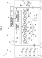
- Fig. 1 is a diagram illustrating an image forming apparatus 1.
- the image forming apparatus 1 includes a paper feeding unit 1A, a printing unit 1B, and a paper discharge unit 1C.
- the paper feeding unit 1A includes a first paper accommodation portion 11 to a fourth paper accommodation portion 14 that accommodate paper P as an example of a recording medium.
- the paper feeding unit 1A is provided with feeding rolls 15 to 18 that are provided respectively corresponding to the first paper accommodation portion 11 to the fourth paper accommodation portion 14, and that feed the paper P accommodated in each paper accommodation portion to a conveyance route connected to the printing unit 1B.
- the printing unit 1B includes an image forming portion 20 that forms an image on the paper P.
- the printing unit 1B is provided with a control unit 21 that controls each unit of the image forming apparatus 1.
- the printing unit 1B also includes an image processing unit 22.
- the image processing unit 22 performs image processing on image data transmitted from an image reading apparatus 4 and a personal computer (PC) 5.
- the printing unit 1B is provided with a user interface (UI) 23 that is configured by a touch panel or the like and that notifies a user of information and receives an input of information from the user.
- UI user interface
- the image forming portion 20 as an example of an image forming section is provided with six image forming units 30T, 30P, 30Y, 30M, 30C, and 30K (hereinafter simply referred to as "image forming unit 30") arranged in parallel at regular intervals.
- Each image forming unit 30 includes a photosensitive drum 31 on which an electrostatic latent image is formed while rotating in a direction of arrow A, a charging roll 32 that charges a surface of the photosensitive drum 31, a developing device 33 that develops the electrostatic latent image formed on the photosensitive drum 31, and a drum cleaner 34 that removes toner or the like on the surface of the photosensitive drum 31.
- the photosensitive drum 31 is an example of an image holder.
- the image forming portion 20 is provided with a laser exposure device 26 that exposes each photosensitive drum 31 of each image forming unit 30 with laser light.
- each image forming unit 30 may be provided with a light source such as a light emitting diode (LED), and the exposure of the photosensitive drum 31 may be performed using light emitted from the light source.
- a light source such as a light emitting diode (LED)
- the respective image forming units 30 have a similar configuration except for the toner housed in the developing device 33.
- the image forming units 30Y, 30M, 30C, and 30K form yellow (Y), magenta (M), cyan (C), and black (K) toner images, respectively.
- the image forming units 30T and 30P form toner images using toner corresponding to corporate colors, foamed toner for braille, fluorescent toner, toner to improve glossiness, and the like.
- the image forming units 30T and 30P form toner images using special color toner.
- the image forming portion 20 is provided with an intermediate transfer belt 41 to which the toner image of each color formed on the photosensitive drum 31 of each image forming unit 30 is transferred.
- the image forming portion 20 is provided with a primary transfer roll 42 that transfers each color toner image of each image forming unit 30 onto the intermediate transfer belt 41 at a primary transfer portion T1.
- the image forming portion 20 is provided with a secondary transfer roll 40 that transfers the toner images transferred onto the intermediate transfer belt 41 all at once onto the paper P at a secondary transfer portion T2.
- the image forming portion 20 is provided with a belt cleaner 45 that removes toner or the like on the surface of the intermediate transfer belt 41, and a fixing device 80 that fixes the secondarily transferred image onto the paper P.
- the developing device 33 is an example of a developing section
- the intermediate transfer belt 41 is an example of a transfer section
- the fixing device 80 is an example of a fixing section.
- the image forming portion 20 performs an image forming operation on the basis of a control signal from the control unit 21.
- image processing is performed by the image processing unit 22 on the image data input from the image reading apparatus 4 or the PC 5, and the image data after the image processing is performed is supplied to the laser exposure device 26.
- the photosensitive drum 31 is irradiated by the laser exposure device 26 with the laser light modulated with the image data obtained from the image processing unit 22.
- the electrostatic latent image is formed on the photosensitive drum 31.
- the formed electrostatic latent image is developed by the developing device 33, and a magenta toner image is formed on the photosensitive drum 31.
- Each color toner image formed in each image forming unit 30 is sequentially electrostatically transferred by the primary transfer roll 42, onto the intermediate transfer belt 41 that rotates in a direction of arrow C in Fig. 1 , and superimposed toner images are formed on the intermediate transfer belt 41.
- the superimposed toner images formed on the intermediate transfer belt 41 are conveyed to the secondary transfer portion T2 that is configured by the secondary transfer roll 40 and a backup roll 49, as the intermediate transfer belt 41 is moved.
- the paper P is taken out from the first paper accommodation portion 11 by, for example, the feeding roll 15, and then is conveyed to a position of a registration roll 74 via the conveyance route.
- the paper P is supplied from the registration roll 74 to the secondary transfer portion T2 at the same time.
- the superimposed toner images are electrostatically transferred all at once onto the paper P by the action of a transfer electric field formed between the secondary transfer roll 40 and the backup roll 49.
- the paper P on which the unfixed toner image is formed is pressurized and heated, and fixing processing of the toner image on the paper P is performed.
- the paper P on which the fixing processing has been performed is conveyed to a paper stacking portion (not illustrated) after passing through a curl correction portion 81 provided in the paper discharge unit 1C.
- Fig. 2 is a diagram illustrating the developing device 33 of the image forming apparatus 1.
- the developing device 33 includes an accommodation portion 331 that accommodates a developer (not illustrated) therein.
- the accommodation portion 331 is configured by an accommodation case 332 made of resin.
- Such a developer is configured by magnetic carrier and colored toner, and is a so-called two-component developer.
- the accommodation case 332 of the developing device 33 is arranged to extend along a direction perpendicular to the paper surface of Fig. 2 , which is a direction from the front side to the rear side of the image forming apparatus 1 (refer to Fig. 1 ), and has a front side member (not illustrated) on the front side and a rear side member (not illustrated) on the rear side.
- the accommodation case 332 is provided with an opening portion 333 at a location facing the photosensitive drum 31 (refer to Fig. 1 ).
- a developing roll 334 that causes the developer to adhere to the surface of the photosensitive drum 31 is provided in the opening portion 333.
- the developing roll 334 holds the developer to be supplied to the photosensitive drum 31.
- a position at which the developer of the developing roll 334 is supplied to the photosensitive drum 31 is sometimes referred to as a developing position T0 (for example, refer to Figs. 3A to 3C ).
- the developing roll 334 as an example of the developer holder is formed in a cylindrical shape, and is arranged to extend along the direction from the front side to the rear side of the image forming apparatus 1. Additionally, the developing roll 334 is arranged along a longitudinal direction of the developing device 33.
- the developing roll 334 is provided with a developing sleeve 334A that is configured by a cylindrical body and is rotationally driven, and with a magnet roll 334B arranged on the inner side of the developing sleeve 334A.
- the developing sleeve 334A is configured by metal such as SUS, for example.
- the developing sleeve 334A rotates in a direction of arrow D in the figure.
- the developing roll 334 is an example of the developer holder.
- the developing sleeve 334A and the photosensitive drum 31 rotate such that the developing sleeve 334A and the photosensitive drum 31 are moved in the same direction at the primary transfer portion T1 (refer to Fig. 1 ) between the developing roll 334 and the photosensitive drum 31.
- the developing device 33 is provided with a layer regulating member 335 that regulates a layer thickness of the developer held on the developing roll 334.
- the developing device 33 is provided with a first conveyance member 336 and a second conveyance member 337 that convey the developer.
- the first conveyance member 336 and the second conveyance member 337 are provided on a side opposite to the side where the photosensitive drum 31 (refer to Fig. 1 ) is installed with respect to the developing roll 334.
- the first conveyance member 336 includes a rotation axis along a rotation axis of the developing sleeve 334A that is rotationally driven, rotates around the rotation axis, and conveys the developer in the accommodation portion 331.
- new toner or toner to which a very small amount of carrier is added is conveyed in circulation by being agitated and conveyed between the first conveyance member 336 and the second conveyance member 337. More specifically, by delivering the developer through connection ports formed at both ends of a partition wall extending in an axial direction, the developer agitated by the first conveyance member 336 is agitated by the second conveyance member 337, and can be further agitated by the first conveyance member 336.
- circulation routes as routes circulating in the axial direction due to the rotation of each of the first conveyance member 336 and the second conveyance member 337 are formed.
- a third conveyance member 338 adjacent to the second conveyance member 337 is provided.
- a pickup roll 339 positioned above the third conveyance member 338 is provided.
- the conveyance route formed by the rotation of the third conveyance member 338 is connected to the above-mentioned circulation route, and the developer from the circulation route is delivered.
- the third conveyance member 338 supplies the developer to the pickup roll 339.
- the pickup roll 339 supplies the developer to the developing roll 334.
- the first conveyance member 336 performs the conveyance to the front side of the page
- the second conveyance member 337 performs the conveyance to the back side of the page
- the third conveyance member 338 performs the conveyance to the front side of the page.
- the developing roll 334, the layer regulating member 335, the first conveyance member 336, the second conveyance member 337, the third conveyance member 338, and the pickup roll 339 are arranged substantially parallel to the photosensitive drum 31 (refer to Fig. 1 ).
- the developing device 33 according to the first exemplary embodiment includes a seal roll 51 as an example of a first member (for example, refer to Figs. 3A to 3C ).
- the developing device 33 according to the second exemplary embodiment includes a carrier collection roll 53 as an example of the first member (refer to Fig. 10 ).
- Figs. 3A to 3C are diagrams illustrating the developing device 33 according to the first exemplary embodiment
- Fig. 3A illustrates the developing device 33 together with the photosensitive drum 31
- Fig. 3B illustrates an electrode member 52 alone
- Fig. 3C illustrates a positional relationship between the seal roll 51 and the electrode member 52.
- the developing device 33 includes the seal roll 51 provided to face the photosensitive drum 31 and the developing roll 334, and the electrode member 52 provided to be surrounded by the photosensitive drum 31, the developing roll 334, and the seal roll 51.
- the seal roll 51 is an example of the first member
- the electrode member 52 is an example of a second member.
- the seal roll 51 is positioned on the downstream side of the developing position T0 where the developer of the developing roll 334 is supplied to the photosensitive drum 31, and rotates in a clockwise direction that is a direction opposite to a counterclockwise direction in which the developing roll 334 rotates.
- the seal roll 51 has a smaller diameter than the diameters of the photosensitive drum 31 and the developing roll 334.
- the downstream side here refers to a downstream side in the rotation direction of the photosensitive drum 31 or the developing roll 334 with respect to the developing position T0.
- the electrode member 52 is a fixed member.
- the electrode member 52 has a shape based on a triangular shape that can be accommodated in a space formed by the developing roll 334, the photosensitive drum 31, and the seal roll 51, as illustrated in Fig. 3A .
- the space here is a region surrounded by tangents of the developing roll 334, the photosensitive drum 31, and the seal roll 51, and is an example of a region between the developer holder the image holder, and the first member.
- the electrode member 52 has a surface 52a facing the developing roll 334 between the developing roll 334, the photosensitive drum 31, and the seal roll 51.
- the surface 52a is an example of a surface facing the developer holder, and is an example of a slope.
- the electrode member 52 has the above-mentioned surface 52a, a surface 52b that is formed at a position adjacent to the surface 52a to face the developing roll 334, a surface 52c that is formed at a position adjacent to the surface 52b to face the seal roll 51, and a surface 52d that is formed at a position adjacent to the surfaces 52c and 52a to face the photosensitive drum 31.
- the surface 52a of the electrode member 52 is provided in a tangential direction of the developing roll 334 so that the distance from the developing roll 334 is not changed from an upstream end portion to a downstream end portion of the surface 52a. Note that the surface 52a may be provided in a direction other than the tangential direction.
- the electrode member 52 has a polygonal shape in which the surface 52b is formed by cutting out one corner 52e near the developing roll 334 and the seal roll 51 in the triangular shape.
- the surface 52b of the electrode member 52 is an example of a surface facing the developer holder.
- the surface 52b of the electrode member 52 is provided at a position adjacent to the seal roll 51, and extends in a direction toward a center 51a of the seal roll 51. In this manner, the electrode member 52 is arranged such that a gap ⁇ 1 between the electrode member 52 and the seal roll 51 is small.
- the surface 52b is not limited to the case of extending in the direction toward the center 51a of the seal roll 51, and may be configured to extend in other directions. It is preferable that the other directions here are, for example, directions that become closer to the seal roll 51 as the surface 52b approaches the seal roll 51.
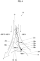
- Figs. 4 and 5 are diagrams illustrating an action of the potential applied to the electrode member 52
- Fig. 4 illustrates a case of the first exemplary embodiment
- Fig. 5 illustrates a comparative example. Note that in Figs. 4 and 5 , the direction of the electric field is indicated by thin dashed arrows.
- illustration of a developer layer 60 illustrated in Figs. 6 and 7 which will be described later, is omitted for convenience of description.
- a potential of -500 V is applied to the developing roll 334, and a potential of -800 V is applied to the seal roll 51.
- a potential of -600 V which is an intermediate potential between the potential of the developing roll 334 and the potential of the seal roll 51, is applied to the electrode member 52. In this manner, an electric field that collects the floating toner is formed.
- the power supply to the electrode member 52 can be divided from the power supply of the seal roll 51.
- the photosensitive drum 31 has a potential of -200 to -620 V More specifically, a part of the photosensitive drum 31 where the electrostatic latent image is formed has a potential of -200 V, and a part of the photosensitive drum 31 where the electrostatic latent image is not formed has a potential of -620 V
- the positive (+) side is the developing roll 334.
- the positive (+) side is the electrode member 52.
- the above-mentioned floating toner may include normal electrode toner 60a (indicated by a white circle) which is negatively charged (-), and reverse electrode toner 60b (indicated by a black circle) which is positively charged (+). Although it is assumed that the floating toner does not include the reverse electrode toner 60b, the reverse electrode toner 60b may be included.
- the amount of the normal electrode toner 60a is greater than the amount of the reverse electrode toner 60b, the ratio thereof fluctuates depending on the decrease in the charge amount and deterioration of the developer due to various conditions such as the ratio of toner in the developer or the like, and a case where the reverse electrode toner 60b is included in about 10% of the floating toner can be described as an example.
- the airflow includes an airflow passing between the photosensitive drum 31 and the electrode member 52 and an airflow passing between the developing roll 334 and the electrode member 52.
- the gap ⁇ 2 in a case of comparing a gap ⁇ 2 between the photosensitive drum 31 and the electrode member 52 and a gap ⁇ 3 between the developing roll 334 and the electrode member 52, the gap ⁇ 2 is smaller than the gap ⁇ 3 ( ⁇ 2 ⁇ ⁇ 3). Therefore, the amount of airflow passing through the gap ⁇ 3 is large, and the amount of airflow passing through the gap 62 is small.
- the surface 52a of the electrode member 52 faces toward the developing roll 334 to block the airflow passing through the gap ⁇ 2 and to promote the airflow passing through the gap ⁇ 3.
- the normal electrode toner 60a in the floating toner is drawn toward the developing roll 334 by the action of repelling the electrode member 52 and being attracted to the developing roll 334, as indicated by a thick dashed arrow.
- the reverse electrode toner 60b is drawn toward the electrode member 52 by the action of repelling the developing roll 334 and being attracted to the electrode member 52, as indicated by a thick solid arrow.
- the floating toner moves by riding on the airflow passing through the gap ⁇ 3.
- the negatively charged normal electrode toner 60a is drawn toward the developing roll 334 between the developing roll 334 and the electrode member 52, while the positively charged reverse electrode toner 60b repels the developing roll 334 and is drawn toward the electrode member 52.
- the positively charged reverse electrode toner 60b that has been drawn toward the electrode member 52 is drawn toward the seal roll 51.
- the surface 52b of the electrode member 52 extends in a center direction of the seal roll 51 such that a gap ⁇ 4 between the electrode member 52 and the seal roll 51 does not become large.
- the reverse electrode toner 60b drawn to the electrode member 52 is prevented from riding on the airflow passing through the gap ⁇ 2 from the gap 64.
- the size relationship of the gaps ⁇ 1 to ⁇ 4 is not limited to that described above, and the gaps ⁇ 1 to ⁇ 4 may have a size relationship different from the size relationship described above.
- a potential of -500 V is applied to the developing roll 334
- a potential of -800 V is applied to the seal roll 51
- a potential of -600 V is applied as the intermediate potential to the electrode member 52. Due to this intermediate potential, the potential difference between the developing roll 334 and the electrode member 52 is 100 V, and the potential difference between the seal roll 51 and the electrode member 52 is 200 V
- a potential difference is not limited thereto.
- the gap ⁇ 3 between the developing roll 334 and the electrode member 52 and the gap ⁇ 4 between the electrode member 52 and the seal roll 51 may be compared, and the potential difference of the closer one may be set to be smaller than the potential difference of the far one. More specifically, in the present exemplary embodiment, as illustrated in Fig. 4 , since the gap ⁇ 4 is smaller than the gap ⁇ 3 ( ⁇ 4 ⁇ ⁇ 3), the potential difference between the electrode member 52 and the seal roll 51 is set to be smaller than the potential difference between the developing roll 334 and the electrode member 52. That is, in this case, the intermediate potential applied to the electrode member 52 is, for example, -700 V
- the gap ⁇ 3 in this case is the shortest distance between the developing roll 334 and the electrode member 52
- the gap ⁇ 4 refers to a position 60d (refer to Fig. 6 ) closest to the electrode member 52 among the contact positions in a case where the developer layer 60 held by the developing roll 334 comes into contact with the seal roll 51 (refer to Fig. 6 ).
- the position 60d here is a position of the upstream end of the developer layer 60 in contact with the seal roll 51 in the rotational direction of the seal roll 51.
- the gap ⁇ 3 described above is an example of the distance between the second member and the developer holder, and the gap ⁇ 4 is an example of the distance between the second member and the first member.
- the intermediate potential it is conceivable to set the potential difference according to the ratio of gaps. For example, a ratio between the gap ⁇ 3 and the gap ⁇ 4 is obtained, and the intermediate potential is set by dividing the ratio proportionally. More specifically, in a case where the potential difference between the developing roll 334 and the seal roll 51 is 300 V and the ratio between the gap ⁇ 3 and the gap ⁇ 4 is 5:1, the potential difference for the gap ⁇ 3 is 250 V, and the potential difference for the gap ⁇ 4 is 50 V That is, in this case, the intermediate potential applied to the electrode member 52 is -750 V
- a configuration in which the electrode member 52 illustrated in Fig. 4 is not included is illustrated in Fig. 5 .
- the configuration other than the configuration in which the electrode member 52 is not included is the same as in the case of Fig. 4 , and the use of the thick solid arrow, the thick dashed arrow, the thin dashed arrow, and the arrow k is the same as in the case of Fig. 4 .
- reverse electrode toner 60c not illustrated in Fig. 4 is illustrated in Fig. 5 .
- the normal electrode toner 60a is drawn to the developing roll 334
- the reverse electrode toner 60b is drawn to the seal roll 51
- the reverse electrode toner 60c moves by riding on the airflow passing between the photosensitive drum 31 and the seal roll 51. In this manner, the reverse electrode toner 60c leaks to the outside of the device, and the amount of leakage is not suppressed.
- Fig. 6 is a diagram illustrating a case where the developer held by the developing roll 334 comes into contact with the seal roll 51.
- the developer layer 60 held by the developing roll 334 is illustrated in Fig. 6 .
- the developer layer 60 comes into contact with the photosensitive drum 31 at the developing position T0, and also comes into contact with the seal roll 51 at a position on the downstream side thereof. That is, the space between the developing roll 334 and the seal roll 51 is closed by the developer layer 60.
- the normal electrode toner 60a and the reverse electrode toner 60b as the floating toner that moves by riding on the airflow passing through the gap ⁇ 3 between the developing roll 334 and the electrode member 52 are collected by the developer layer 60. In this manner, the leakage of the floating toner to the outside of the developing device 33 is suppressed.
- Fig. 6 illustrates a state in which the developer layer 60 comes into contact with the seal roll 51, but the present invention is not limited thereto, and the developer layer 60 may not come into contact with the seal roll 51.
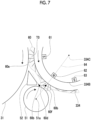
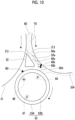
- Fig. 7 is a diagram illustrating a magnetic field of the developer layer 60 held by the developing roll 334.
- the magnet roll 334B of the developing roll 334 is provided with a plurality of magnetic poles arranged along a circumferential direction. More specifically, the magnet roll 334B is provided with, as the plurality of magnetic poles, for example, an S pole 61 at a position corresponding to the developing position T0, and an N pole 62 is provided at a position facing the seal roll 51 on the downstream side thereof. Further, an S pole 63 is provided on the downstream side.
- the layer thickness of the developer layer 60 is changed depending on the position in the circumferential direction.
- the layer thickness in contact with the photosensitive drum 31 is formed by the S pole 61
- the layer thickness in contact with the seal roll 51 is formed by the N pole 62.
- magnetic lines of force are formed by the magnetic field of the developer layer 60. More specifically, as illustrated in Fig. 7 , a magnetic brush 60e by the magnetic lines of force is formed in the developer layer 60 at the developing position T0, and a magnetic brush 60f by the magnetic lines of force is formed in the developer layer 60 at the position facing the seal roll 51.
- the magnetic brushes 60e and 60f contain the carrier of the developer layer 60.
- the magnetic brush 60f stands up to overlap a dashed line 64 connecting a center 334C of the developing roll 334 and the center 51a of the seal roll 51.
- the above-mentioned N pole 62 of the developing roll 334 is arranged toward the center 51a of the seal roll 51.
- the N pole 62 is a magnet for forming the magnetic brush 60f toward the center 51a of the seal roll 51.
- the magnet is arranged from the center 334C of the developing roll 334 toward the center 51a of the seal roll 51 such that the magnetic brush 60f from the developing roll 334 stands up.
- the direction of the magnetic brushes 60e and 60f is the direction of the magnetic lines of force.
- the S poles 61 and 63 which are magnetic poles different from the N pole 62, are arranged on the upstream side and the downstream side of the N pole 62 of the developing roll 334.
- the N pole 62 is adjacent to the S poles 61 and 63.
- the magnetic brushes other than the magnetic brushes 60e and 60f are inclined in accordance with the magnetic field generated by such adjacent arrangement.
- the N pole 62 is an example of a magnet
- the S poles 61 and 63 are examples of different polarity magnets.
- the plurality of magnetic poles in the developing roll 334 are not limited to the above-mentioned arrangement of magnets, and other arrangements of magnets may be adopted.
- the tip of the magnetic brush 60f in the developer layer 60 moves faster than the part other than the tip, and has a high ability to collect the reverse electrode toner 60b during the contact with the seal roll 51. Therefore, even in a case where the reverse electrode toner 60b gathered around the position 60d of the electrode member 52 due to the electric field formed by the electrode adheres to the seal roll 51, the sliding force of the magnetic brush 60f with the developer is increased, and the reverse electrode toner 60b is collected in the developer layer 60.
- the magnetic brush 60f and magnetic brushes 60g and 60h stand along the direction of the magnetic lines of force, it is not necessary to increase the positioning accuracy of the seal roll 51 with respect to the developing roll 334. That is, even in a case where the error in the distance between the developing roll 334 and the seal roll 51 is set to a large value, it is possible to collect the reverse electrode toner 60b that has adhered to the seal roll 51.
- Fig. 8 is a diagram illustrating the magnetic brush of the developer layer 60 held by the developing roll 334. Note that, in Fig. 8 , a normal line 334D of the developing roll 334 is illustrated instead of the outer circumferential surface of the developing roll 334 for convenience of calculating the magnetic lines of force. The normal line 334D intersects the line 64 (refer to Fig. 7 ).
- the magnetic brushes 60f, 60g, and 60h are positioned within a range of a predetermined angle ⁇ with respect to the line 64. More specifically, the angle ⁇ is 30 degrees in the present exemplary embodiment, the magnetic brush 60g is inclined by 30 degrees to the upstream side with respect to the line 64, and the magnetic brush 60h is inclined by 30 degrees to the downstream side with respect to the line 64.
- the angle ⁇ is determined by various boundary conditions and is an example of a predetermined angle.
- the developer in the developer layer 60 comes into contact with the seal roll 51 within a range in which each of the magnetic brushes 60g and 60h on the upstream side and the downstream side has the angle ⁇ (30 degrees in the present exemplary embodiment) with respect to the line 64.
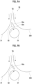
- Figs. 9A and 9B are diagrams illustrating modification examples of the electrode member 52 according to the first exemplary embodiment, Fig. 9A is one modification example, and Fig. 9B is another modification example.
- the electrode member 52 has a triangular shape, and unlike the first exemplary embodiment (refer to Figs. 3A to 3C ), no notch is formed at the corner 52e. As in the other modification example, the electrode member 52 has the surface 52a facing the developing roll 334.
- the electrode member 52 has plate shape, and has a rectangular cross section. Also in the other modification example, the electrode member 52 has the surface 52a facing the developing roll 334.
- Fig. 10 is a diagram illustrating the developing device 33 according to a second exemplary embodiment, and corresponds to Fig. 6 among Figs. 3A to 9B illustrating the first exemplary embodiment. Therefore, the description of parts common to Fig. 6 may be omitted.
- the carrier collection roll 53 as an example of the first member is provided. More specifically, the developing device 33 according to the second exemplary embodiment does not include the seal roll 51 (for example, refer to Figs. 3A to 3C ) included in the developing device 33 according to the first exemplary embodiment, and the carrier collection roll 53 is arranged at the position of the seal roll 51.
- the seal roll 51 can be replaced with the carrier collection roll 53.
- the carrier collection roll 53 is an example of the first member.
- the carrier collection roll 53 is provided with a sleeve 53A that is configured by a cylindrical body and is rotationally driven, and with a magnet roll 53B arranged on the inner side of the sleeve 53A.
- the magnet roll 53B of the carrier collection roll 53 is provided with a plurality of magnetic poles arranged along the circumferential direction. More specifically, the magnet roll 53B is provided with, as the plurality of magnetic poles, for example, an S pole 65 at a location where the developer layer 60 comes into contact with the sleeve 53A, and a N pole 66 on the upstream side of the location facing the electrode member 52. Further, the magnet roll 53B is provided with, as the plurality of magnetic poles, an S pole 67 at a position shifted by 180 degrees from the location where the developer layer 60 comes into contact with the sleeve 53A.
- the reverse electrode toner 60i Since the reverse electrode toner 60i is positively charged, the reverse electrode toner 60i is easily drawn to the N pole 66 of the carrier collection roll 53. Therefore, in a case where the reverse electrode toner 60i adheres to the circumferential surface of the sleeve 53A, the reverse electrode toner 60i is collected into the developer layer 60 by the rotation of the sleeve 53A.
- the floating toner in the developing device can be efficiently collected as compared with a case where an electric field is provided that collects the normal electrode toner but does not collect the reverse polarity toner.
- the efficiency of collecting the developer adhering to the first member can be improved as compared with a case without a configuration in which the developer holder has the magnet for forming the brush containing the carrier of the developer, toward the center direction of the first member.
- the efficiency of collecting the developer adhering to the first member can be improved as compared with a case without a configuration in which the magnet is adjacent to different polarity magnets, which have magnetic poles different from the magnet and are arranged on the upstream side and the downstream side of the magnet in the developer holder.
- the positioning accuracy of the first member with respect to the developer holder can be lowered as compared with a case without a configuration in which the developer comes into contact with the first member in a range in which, among brushes, each of the brushes on the upstream side and the downstream side has a predetermined angle with respect to the center direction.
- the leakage of the floating toner to the outside of the device can be suppressed as compared with a case in which the intermediate potential of the second member is not set such that, among the distance between the second member and the developer holder and the distance between the second member and the first member, the potential difference of the shorter distance is smaller than the potential difference of the far distance.
- the leakage of the floating toner to the outside of the device can be suppressed as compared with a case without a configuration in which the setting is performed according to the ratio of the distance between the second member and the developer holder and the distance between the second member and the first member.
- the leakage of the floating toner to the outside of the device can be suppressed as compared with a case without a configuration in which the second member has a polygonal shape having the surface as the slope.
- the amount of the floating toner to be collected can be increased as compared with a case without a configuration in which the polygonal shape has the surface facing the developer holder at the position adjacent to the first member.
- the amount of the floating toner to be collected can be increased as compared with a case without a configuration in which the surface facing the developer holder extends in a center direction of the first member.
- the amount of the floating toner to be collected can be increased as compared with a case without a configuration in which the slope is provided in the tangential direction of the developer holder such that the distance from the developer holder is not changed from one end portion to the other end portion of the slope.
- the floating toner in the developing device can be efficiently collected as compared with a case where an electric field is provided that collects the normal electrode toner but does not collect the reverse polarity toner.
Landscapes
- Physics & Mathematics (AREA)
- General Physics & Mathematics (AREA)
- Dry Development In Electrophotography (AREA)
- Developing For Electrophotography (AREA)
Abstract
Description
- The present invention relates to a developing device and an image forming apparatus.
- For example,
JP1994-11970A - Here, in a case of collecting floating toner inside a developing device to prevent the floating toner from leaking to the outside, since the floating toner includes normal electrode toner and reverse polarity toner which have different magnetic poles, an electric field used to collect the normal electrode toner cannot collect the reverse polarity toner, which is difficult to efficiently collect the floating toner.
- An object of the present invention is to efficiently collect the floating toner in the developing device as compared with a case where an electric field is provided that collects the normal electrode toner but does not collect the reverse polarity toner.
- According to a first aspect of the present disclosure, there is provided a developing device including a developer holder that holds a developer containing toner and carrier and being supplied to an image holder forming an electrostatic latent image; a first member that is provided on a downstream side of a developing position that is a position where the developer held by the developer holder is supplied to the image holder; and a second member that is provided between the developer holder, the image holder, and the first member, that has a surface facing the developer holder, and to which an intermediate potential as a potential between a potential applied to the developer holder and a potential applied to the first member is applied.
- According to a second aspect of the present disclosure, there is provided the developing device according to the first aspect, in which the developer holder may have a magnet for forming a brush containing the carrier of the developer, toward a center direction of the first member.
- According to a third aspect of the present disclosure, there is provided the developing device according to the second aspect, in which the magnet may be adjacent to different polarity magnets, which have magnetic poles different from the magnet and are arranged on an upstream side and a downstream side of the magnet in the developer holder.
- According to a fourth aspect of the present disclosure, there is provided the developing device according to the second aspect, in which in a case where reverse polarity toner drawn to the second member is collected by the developer that comes into contact with the first member on the downstream side of the position where the developer of the developer holder is supplied, the developer may come into contact with the first member in a range in which, among brushes, each of the brushes on the upstream side and the downstream side has a predetermined angle with respect to the center direction.
- According to a fifth aspect of the present disclosure, there is provided the developing device according to the first aspect, in which the intermediate potential of the second member may be set such that, among a distance between the second member and the developer holder and a distance between the second member and the first member, a potential difference of the shorter distance is smaller than a potential difference of the far distance.
- According to a sixth aspect of the present disclosure, there is provided the developing device according to the fifth aspect, in which the setting may be performed according to a ratio of the distance between the second member and the developer holder and the distance between the second member and the first member.
- According to a seventh aspect of the present disclosure, there is provided the developing device according to any one of the first aspect to the sixth aspect, in which the second member may have a polygonal shape having the surface as a slope.
- According to an eighth aspect of the present disclosure, there is provided the developing device according to the seventh aspect, in which the polygonal shape may have a surface facing the developer holder at a position adjacent to the first member.
- According to a ninth aspect of the present disclosure, there is provided the developing device according to the eighth aspect, in which the surface facing the developer holder may extend in a center direction of the first member.
- According to a tenth aspect of the present disclosure, there is provided the developing device according to any one of the seventh aspect to the ninth aspect, in which the slope may be provided in a tangential direction of the developer holder such that a distance from the developer holder is not changed from one end portion to the other end portion of the slope.
- According to an eleventh aspect of the present disclosure, there is provided an image forming apparatus including an image holder that forms an electrostatic latent image; a developing section that develops the electrostatic latent image formed on the image holder into a toner image; a transfer section that transfers the toner image by the developing section onto a recording material; and a fixing section that fixes the toner image transferred onto the recording material to the recording material, wherein the developing section includes a developer holder that holds a developer containing toner and carrier and being supplied to the image holder forming the electrostatic latent image, a first member that is provided on a downstream side of a developing position that is a position where the developer held by the developer holder is supplied to the image holder, and a second member that is provided between the developer holder, the image holder, and the first member, that has a surface facing the developer holder, and to which an intermediate potential as a potential between a potential applied to the developer holder and a potential applied to the first member is applied.
- According to the first aspect, the floating toner in the developing device can be efficiently collected as compared with a case where an electric field is provided that collects the normal electrode toner but does not collect the reverse polarity toner.
- According to the second aspect, the efficiency of collecting the developer adhering to the first member can be improved as compared with a case without a configuration in which the developer holder has the magnet for forming the brush containing the carrier of the developer, toward the center direction of the first member.
- According to the third aspect, the efficiency of collecting the developer adhering to the first member can be improved as compared with a case without a configuration in which the magnet is adjacent to different polarity magnets, which have magnetic poles different from the magnet and are arranged on the upstream side and the downstream side of the magnet in the developer holder.
- According to the fourth aspect, the positioning accuracy of the first member with respect to the developer holder can be lowered as compared with a case without a configuration in which the developer comes into contact with the first member in a range in which, among brushes, each of the brushes on the upstream side and the downstream side has a predetermined angle with respect to the center direction.
- According to the fifth aspect, the leakage of the floating toner to the outside of the device can be suppressed as compared with a case in which the intermediate potential of the second member is not set such that, among the distance between the second member and the developer holder and the distance between the second member and the first member, the potential difference of the shorter distance is smaller than the potential difference of the far distance.
- According to the sixth aspect, the leakage of the floating toner to the outside of the device can be suppressed as compared with a case without a configuration in which the setting is performed according to the ratio of the distance between the second member and the developer holder and the distance between the second member and the first member.
- According to the seventh aspect, the leakage of the floating toner to the outside of the device can be suppressed as compared with a case without a configuration in which the second member has a polygonal shape having the surface as the slope.
- According to the eighth aspect, the amount of the floating toner to be collected can be increased as compared with a case without a configuration in which the polygonal shape has the surface facing the developer holder at the position adjacent to the first member.
- According to the ninth aspect, the amount of the floating toner to be collected can be increased as compared with a case without a configuration in which the surface facing the developer holder extends in a center direction of the first member.
- According to the tenth aspect, the amount of the floating toner to be collected can be increased as compared with a case without a configuration in which the slope is provided in the tangential direction of the developer holder such that the distance from the developer holder is not changed from one end portion to the other end portion of the slope.
- According to the eleventh aspect, the floating toner in the developing device can be efficiently collected as compared with a case where an electric field is provided that collects the normal electrode toner but does not collect the reverse polarity toner.
- Exemplary embodiment(s) of the present invention will be described in detail based on the following figures, wherein:
-
Fig. 1 is a diagram illustrating an image forming apparatus; -
Fig. 2 is a diagram illustrating a developing device of the image forming apparatus; -
Figs. 3A to 3C are diagrams illustrating a developing device according to a first exemplary embodiment,Fig. 3A illustrates the developing device together with a photosensitive drum,Fig. 3B illustrates an electrode member alone, andFig. 3C illustrates a positional relationship between a seal roll and the electrode member; -
Fig. 4 is a diagram illustrating an action of a potential applied to the electrode member according to the first exemplary embodiment; -
Fig. 5 is a diagram illustrating an action of a potential applied to the electrode member according to a comparative example; -
Fig. 6 is a diagram illustrating a case where a developer held by a developing roll comes into contact with the seal roll; -
Fig. 7 is a diagram illustrating a magnetic field of a developer layer held by the developing roll; -
Fig. 8 is a diagram illustrating a magnetic brush of the developer layer held by the developing roll; -
Figs. 9A and 9B are diagrams illustrating modification examples of the electrode member according to the first exemplary embodiment,Fig. 9A is one modification example, andFig. 9B is another modification example; and -
Fig. 10 is a diagram illustrating a developing device according to a second exemplary embodiment. - Hereinafter, exemplary embodiments of the invention will be described in detail with reference to the accompanying drawings.
-
Fig. 1 is a diagram illustrating an image forming apparatus 1. - The image forming apparatus 1 according to the present exemplary embodiment includes a
paper feeding unit 1A, aprinting unit 1B, and apaper discharge unit 1C. - The
paper feeding unit 1A includes a firstpaper accommodation portion 11 to a fourthpaper accommodation portion 14 that accommodate paper P as an example of a recording medium. - In addition, the
paper feeding unit 1A is provided withfeeding rolls 15 to 18 that are provided respectively corresponding to the firstpaper accommodation portion 11 to the fourthpaper accommodation portion 14, and that feed the paper P accommodated in each paper accommodation portion to a conveyance route connected to theprinting unit 1B. - The
printing unit 1B includes animage forming portion 20 that forms an image on the paper P. In addition, theprinting unit 1B is provided with acontrol unit 21 that controls each unit of the image forming apparatus 1. - In addition, the
printing unit 1B also includes animage processing unit 22. Theimage processing unit 22 performs image processing on image data transmitted from animage reading apparatus 4 and a personal computer (PC) 5. - In addition, the
printing unit 1B is provided with a user interface (UI) 23 that is configured by a touch panel or the like and that notifies a user of information and receives an input of information from the user. - The
image forming portion 20 as an example of an image forming section is provided with siximage forming units - Each image forming unit 30 includes a
photosensitive drum 31 on which an electrostatic latent image is formed while rotating in a direction of arrow A, acharging roll 32 that charges a surface of thephotosensitive drum 31, a developingdevice 33 that develops the electrostatic latent image formed on thephotosensitive drum 31, and adrum cleaner 34 that removes toner or the like on the surface of thephotosensitive drum 31. - The
photosensitive drum 31 is an example of an image holder. - In addition, the
image forming portion 20 is provided with alaser exposure device 26 that exposes eachphotosensitive drum 31 of each image forming unit 30 with laser light. - Note that the exposure of the
photosensitive drum 31 by thelaser exposure device 26 is not limited to using laser light. For example, each image forming unit 30 may be provided with a light source such as a light emitting diode (LED), and the exposure of thephotosensitive drum 31 may be performed using light emitted from the light source. - The respective image forming units 30 have a similar configuration except for the toner housed in the developing
device 33. Theimage forming units - In addition, the
image forming units image forming units - In addition, the
image forming portion 20 is provided with anintermediate transfer belt 41 to which the toner image of each color formed on thephotosensitive drum 31 of each image forming unit 30 is transferred. - In addition, the
image forming portion 20 is provided with aprimary transfer roll 42 that transfers each color toner image of each image forming unit 30 onto theintermediate transfer belt 41 at a primary transfer portion T1. - In addition, the
image forming portion 20 is provided with asecondary transfer roll 40 that transfers the toner images transferred onto theintermediate transfer belt 41 all at once onto the paper P at a secondary transfer portion T2. - Further, the
image forming portion 20 is provided with abelt cleaner 45 that removes toner or the like on the surface of theintermediate transfer belt 41, and a fixingdevice 80 that fixes the secondarily transferred image onto the paper P. - The developing
device 33 is an example of a developing section, theintermediate transfer belt 41 is an example of a transfer section, and the fixingdevice 80 is an example of a fixing section. - The
image forming portion 20 performs an image forming operation on the basis of a control signal from thecontrol unit 21. - Specifically, in the
image forming portion 20, first, image processing is performed by theimage processing unit 22 on the image data input from theimage reading apparatus 4 or thePC 5, and the image data after the image processing is performed is supplied to thelaser exposure device 26. - Then, for example, in the
image forming unit 30M for magenta (M), after the surface of thephotosensitive drum 31 is charged by the chargingroll 32, thephotosensitive drum 31 is irradiated by thelaser exposure device 26 with the laser light modulated with the image data obtained from theimage processing unit 22. - In this manner, the electrostatic latent image is formed on the
photosensitive drum 31. - The formed electrostatic latent image is developed by the developing
device 33, and a magenta toner image is formed on thephotosensitive drum 31. - Similarly, in the
image forming units image forming units - Each color toner image formed in each image forming unit 30 is sequentially electrostatically transferred by the
primary transfer roll 42, onto theintermediate transfer belt 41 that rotates in a direction of arrow C inFig. 1 , and superimposed toner images are formed on theintermediate transfer belt 41. - The superimposed toner images formed on the
intermediate transfer belt 41 are conveyed to the secondary transfer portion T2 that is configured by thesecondary transfer roll 40 and abackup roll 49, as theintermediate transfer belt 41 is moved. - On the other hand, the paper P is taken out from the first
paper accommodation portion 11 by, for example, the feedingroll 15, and then is conveyed to a position of aregistration roll 74 via the conveyance route. - In a case where the superimposed toner images are conveyed to the secondary transfer portion T2, the paper P is supplied from the
registration roll 74 to the secondary transfer portion T2 at the same time. - Then, at the secondary transfer portion T2, the superimposed toner images are electrostatically transferred all at once onto the paper P by the action of a transfer electric field formed between the
secondary transfer roll 40 and thebackup roll 49. - Thereafter, the paper P on which the superimposed toner images have been electrostatically transferred is conveyed to the fixing
device 80. - In the fixing
device 80, the paper P on which the unfixed toner image is formed is pressurized and heated, and fixing processing of the toner image on the paper P is performed. - Then, the paper P on which the fixing processing has been performed is conveyed to a paper stacking portion (not illustrated) after passing through a
curl correction portion 81 provided in thepaper discharge unit 1C. -
Fig. 2 is a diagram illustrating the developingdevice 33 of the image forming apparatus 1. - The developing
device 33 includes anaccommodation portion 331 that accommodates a developer (not illustrated) therein. Theaccommodation portion 331 is configured by anaccommodation case 332 made of resin. Such a developer is configured by magnetic carrier and colored toner, and is a so-called two-component developer. - The
accommodation case 332 of the developingdevice 33 is arranged to extend along a direction perpendicular to the paper surface ofFig. 2 , which is a direction from the front side to the rear side of the image forming apparatus 1 (refer toFig. 1 ), and has a front side member (not illustrated) on the front side and a rear side member (not illustrated) on the rear side. - The
accommodation case 332 is provided with anopening portion 333 at a location facing the photosensitive drum 31 (refer toFig. 1 ). A developingroll 334 that causes the developer to adhere to the surface of thephotosensitive drum 31 is provided in theopening portion 333. The developingroll 334 holds the developer to be supplied to thephotosensitive drum 31. A position at which the developer of the developingroll 334 is supplied to thephotosensitive drum 31 is sometimes referred to as a developing position T0 (for example, refer toFigs. 3A to 3C ). - The developing
roll 334 as an example of the developer holder is formed in a cylindrical shape, and is arranged to extend along the direction from the front side to the rear side of the image forming apparatus 1. Additionally, the developingroll 334 is arranged along a longitudinal direction of the developingdevice 33. - The developing
roll 334 is provided with a developingsleeve 334A that is configured by a cylindrical body and is rotationally driven, and with amagnet roll 334B arranged on the inner side of the developingsleeve 334A. - The developing
sleeve 334A is configured by metal such as SUS, for example. In addition, the developingsleeve 334A rotates in a direction of arrow D in the figure. - The developing
roll 334 is an example of the developer holder. - Further, in the present exemplary embodiment, the developing
sleeve 334A and thephotosensitive drum 31 rotate such that the developingsleeve 334A and thephotosensitive drum 31 are moved in the same direction at the primary transfer portion T1 (refer toFig. 1 ) between the developingroll 334 and thephotosensitive drum 31. - The developing
device 33 is provided with alayer regulating member 335 that regulates a layer thickness of the developer held on the developingroll 334. - In addition, as illustrated in
Fig. 2 , the developingdevice 33 is provided with afirst conveyance member 336 and asecond conveyance member 337 that convey the developer. - The
first conveyance member 336 and thesecond conveyance member 337 are provided on a side opposite to the side where the photosensitive drum 31 (refer toFig. 1 ) is installed with respect to the developingroll 334. - The
first conveyance member 336 includes a rotation axis along a rotation axis of the developingsleeve 334A that is rotationally driven, rotates around the rotation axis, and conveys the developer in theaccommodation portion 331. - In the developing
device 33 configured as described above, new toner or toner to which a very small amount of carrier is added is conveyed in circulation by being agitated and conveyed between thefirst conveyance member 336 and thesecond conveyance member 337. More specifically, by delivering the developer through connection ports formed at both ends of a partition wall extending in an axial direction, the developer agitated by thefirst conveyance member 336 is agitated by thesecond conveyance member 337, and can be further agitated by thefirst conveyance member 336. In the developingdevice 33, circulation routes as routes circulating in the axial direction due to the rotation of each of thefirst conveyance member 336 and thesecond conveyance member 337 are formed. - In the developing
device 33, athird conveyance member 338 adjacent to thesecond conveyance member 337 is provided. In addition, in the developingdevice 33, apickup roll 339 positioned above thethird conveyance member 338 is provided. - The conveyance route formed by the rotation of the
third conveyance member 338 is connected to the above-mentioned circulation route, and the developer from the circulation route is delivered. Thethird conveyance member 338 supplies the developer to thepickup roll 339. Thepickup roll 339 supplies the developer to the developingroll 334. - For example, the
first conveyance member 336 performs the conveyance to the front side of the page, thesecond conveyance member 337 performs the conveyance to the back side of the page, and thethird conveyance member 338 performs the conveyance to the front side of the page. - Note that the developing
roll 334, thelayer regulating member 335, thefirst conveyance member 336, thesecond conveyance member 337, thethird conveyance member 338, and thepickup roll 339 are arranged substantially parallel to the photosensitive drum 31 (refer toFig. 1 ). - Next, a more specific configuration of the developing
device 33 will be described. As such specific configurations, a first exemplary embodiment and a second exemplary embodiment will be described. The developingdevice 33 according to the first exemplary embodiment includes aseal roll 51 as an example of a first member (for example, refer toFigs. 3A to 3C ). In addition, the developingdevice 33 according to the second exemplary embodiment includes acarrier collection roll 53 as an example of the first member (refer toFig. 10 ). -
Figs. 3A to 3C are diagrams illustrating the developingdevice 33 according to the first exemplary embodiment,Fig. 3A illustrates the developingdevice 33 together with thephotosensitive drum 31,Fig. 3B illustrates anelectrode member 52 alone, andFig. 3C illustrates a positional relationship between theseal roll 51 and theelectrode member 52. - As illustrated in
Fig. 3A , the developingdevice 33 includes theseal roll 51 provided to face thephotosensitive drum 31 and the developingroll 334, and theelectrode member 52 provided to be surrounded by thephotosensitive drum 31, the developingroll 334, and theseal roll 51. Theseal roll 51 is an example of the first member, and theelectrode member 52 is an example of a second member. - The
seal roll 51 is positioned on the downstream side of the developing position T0 where the developer of the developingroll 334 is supplied to thephotosensitive drum 31, and rotates in a clockwise direction that is a direction opposite to a counterclockwise direction in which the developingroll 334 rotates. Theseal roll 51 has a smaller diameter than the diameters of thephotosensitive drum 31 and the developingroll 334. - The downstream side here refers to a downstream side in the rotation direction of the
photosensitive drum 31 or the developingroll 334 with respect to the developing position T0. - Unlike the
seal roll 51, theelectrode member 52 is a fixed member. In addition, in the present exemplary embodiment, theelectrode member 52 has a shape based on a triangular shape that can be accommodated in a space formed by the developingroll 334, thephotosensitive drum 31, and theseal roll 51, as illustrated inFig. 3A . The space here is a region surrounded by tangents of the developingroll 334, thephotosensitive drum 31, and theseal roll 51, and is an example of a region between the developer holder the image holder, and the first member. - In more detail, the
electrode member 52 has asurface 52a facing the developingroll 334 between the developingroll 334, thephotosensitive drum 31, and theseal roll 51. Thesurface 52a is an example of a surface facing the developer holder, and is an example of a slope. - To describe the
electrode member 52 in more detail, as illustrated inFig. 3B , theelectrode member 52 has the above-mentionedsurface 52a, asurface 52b that is formed at a position adjacent to thesurface 52a to face the developingroll 334, asurface 52c that is formed at a position adjacent to thesurface 52b to face theseal roll 51, and asurface 52d that is formed at a position adjacent to thesurfaces photosensitive drum 31. - The
surface 52a of theelectrode member 52 is provided in a tangential direction of the developingroll 334 so that the distance from the developingroll 334 is not changed from an upstream end portion to a downstream end portion of thesurface 52a. Note that thesurface 52a may be provided in a direction other than the tangential direction. - In addition, the
electrode member 52 has a polygonal shape in which thesurface 52b is formed by cutting out onecorner 52e near the developingroll 334 and theseal roll 51 in the triangular shape. - The
surface 52b of theelectrode member 52 is an example of a surface facing the developer holder. - In more detail, as illustrated in
Fig. 3C , thesurface 52b of theelectrode member 52 is provided at a position adjacent to theseal roll 51, and extends in a direction toward acenter 51a of theseal roll 51. In this manner, theelectrode member 52 is arranged such that a gap δ1 between theelectrode member 52 and theseal roll 51 is small. - Note that the
surface 52b is not limited to the case of extending in the direction toward thecenter 51a of theseal roll 51, and may be configured to extend in other directions. It is preferable that the other directions here are, for example, directions that become closer to theseal roll 51 as thesurface 52b approaches theseal roll 51. - Next, the potential applied to the
electrode member 52 will be described. -
Figs. 4 and5 are diagrams illustrating an action of the potential applied to theelectrode member 52,Fig. 4 illustrates a case of the first exemplary embodiment, andFig. 5 illustrates a comparative example. Note that inFigs. 4 and5 , the direction of the electric field is indicated by thin dashed arrows. In addition, inFigs. 4 and5 , illustration of adeveloper layer 60 illustrated inFigs. 6 and7 , which will be described later, is omitted for convenience of description. - In the present exemplary embodiment, as illustrated in
Fig. 4 , a potential of -500 V is applied to the developingroll 334, and a potential of -800 V is applied to theseal roll 51. A potential of -600 V, which is an intermediate potential between the potential of the developingroll 334 and the potential of theseal roll 51, is applied to theelectrode member 52. In this manner, an electric field that collects the floating toner is formed. - The power supply to the
electrode member 52 can be divided from the power supply of theseal roll 51. - Note that the
photosensitive drum 31 has a potential of -200 to -620 V More specifically, a part of thephotosensitive drum 31 where the electrostatic latent image is formed has a potential of -200 V, and a part of thephotosensitive drum 31 where the electrostatic latent image is not formed has a potential of -620 V - Hereinafter, the formation of the electric field that collects the floating toner will be described.
- In a case of adopting the above-mentioned relationship of applied potentials, focusing on the developing
roll 334 and theelectrode member 52, the positive (+) side is the developingroll 334. On the other hand, in a case of focusing on theelectrode member 52 and theseal roll 51, the positive (+) side is theelectrode member 52. - In addition, the above-mentioned floating toner may include
normal electrode toner 60a (indicated by a white circle) which is negatively charged (-), andreverse electrode toner 60b (indicated by a black circle) which is positively charged (+). Although it is assumed that the floating toner does not include thereverse electrode toner 60b, thereverse electrode toner 60b may be included. - In a case of comparing the amounts of the
normal electrode toner 60a and thereverse electrode toner 60b in the floating toner, the amount of thenormal electrode toner 60a is greater than the amount of thereverse electrode toner 60b, the ratio thereof fluctuates depending on the decrease in the charge amount and deterioration of the developer due to various conditions such as the ratio of toner in the developer or the like, and a case where thereverse electrode toner 60b is included in about 10% of the floating toner can be described as an example. - Here, in accordance with the rotation of the
photosensitive drum 31 and the developingroll 334, an airflow from the developing position T0 (refer toFig. 6 ) to the downstream side is generated, and thus the floating toner moves by riding on the airflow. More specifically, since theelectrode member 52 is positioned on the downstream side of the developing position T0, the airflow includes an airflow passing between thephotosensitive drum 31 and theelectrode member 52 and an airflow passing between the developingroll 334 and theelectrode member 52. In more detail, in the first exemplary embodiment, in a case of comparing a gap δ2 between thephotosensitive drum 31 and theelectrode member 52 and a gap δ3 between the developingroll 334 and theelectrode member 52, the gap δ2 is smaller than the gap δ3 (δ2 < δ3). Therefore, the amount of airflow passing through the gap δ3 is large, and the amount of airflow passing through thegap 62 is small. In addition, thesurface 52a of theelectrode member 52 faces toward the developingroll 334 to block the airflow passing through the gap δ2 and to promote the airflow passing through the gap δ3. - In addition, by applying the intermediate potential to the
electrode member 52 described above, thenormal electrode toner 60a in the floating toner is drawn toward the developingroll 334 by the action of repelling theelectrode member 52 and being attracted to the developingroll 334, as indicated by a thick dashed arrow. In addition, thereverse electrode toner 60b is drawn toward theelectrode member 52 by the action of repelling the developingroll 334 and being attracted to theelectrode member 52, as indicated by a thick solid arrow. - Due to the action of the intermediate potential of the
electrode member 52, the floating toner moves by riding on the airflow passing through the gap δ3. - Note that a case will be described in which a smaller amount of
reverse electrode toner 60b than thenormal electrode toner 60a rides on the airflow passing through the gap δ2. Focusing on thephotosensitive drum 31 and theelectrode member 52, since the positive (+) side is thephotosensitive drum 31, thereverse electrode toner 60b repels thephotosensitive drum 31 and is attracted to theelectrode member 52. In this manner, it is assumed that thereverse electrode toner 60b is drawn to theelectrode member 52 and adheres to, for example, thesurface 52d. - In the floating toner that moves by riding on the airflow passing through the gap δ3, the negatively charged
normal electrode toner 60a is drawn toward the developingroll 334 between the developingroll 334 and theelectrode member 52, while the positively chargedreverse electrode toner 60b repels the developingroll 334 and is drawn toward theelectrode member 52. - In addition, the positively charged
reverse electrode toner 60b that has been drawn toward theelectrode member 52 is drawn toward theseal roll 51. In addition, thesurface 52b of theelectrode member 52 extends in a center direction of theseal roll 51 such that a gap δ4 between theelectrode member 52 and theseal roll 51 does not become large. - Therefore, the
reverse electrode toner 60b drawn to theelectrode member 52 is prevented from riding on the airflow passing through the gap δ2 from thegap 64. - Note that it is assumed that, even in a case where the
reverse electrode toner 60b moves by riding on the airflow passing through thegap 62, thereverse electrode toner 60b is drawn to theelectrode member 52 and adheres to, for example, thesurface 52d. In this manner, the amount of thereverse electrode toner 60b leaking to the outside of the device by riding on the airflow (arrow k illustrated inFig. 4 ) passing through thegap 62 is suppressed. - In addition, the size relationship of the gaps δ1 to δ4 is not limited to that described above, and the gaps δ1 to δ4 may have a size relationship different from the size relationship described above.
- Here, a setting method of the intermediate potential applied to the
electrode member 52 as an example of the second member will be described. - In the present exemplary embodiment, as described above, a potential of -500 V is applied to the developing
roll 334, a potential of -800 V is applied to theseal roll 51, and a potential of -600 V is applied as the intermediate potential to theelectrode member 52. Due to this intermediate potential, the potential difference between the developingroll 334 and theelectrode member 52 is 100 V, and the potential difference between theseal roll 51 and theelectrode member 52 is 200 V However, such a potential difference is not limited thereto. - For example, it is conceivable to associate the size relationship of the potential differences with the size relationship of the gaps.
- The gap δ3 between the developing
roll 334 and theelectrode member 52 and the gap δ4 between theelectrode member 52 and theseal roll 51 may be compared, and the potential difference of the closer one may be set to be smaller than the potential difference of the far one. More specifically, in the present exemplary embodiment, as illustrated inFig. 4 , since the gap δ4 is smaller than the gap δ3 (δ4 < δ3), the potential difference between theelectrode member 52 and theseal roll 51 is set to be smaller than the potential difference between the developingroll 334 and theelectrode member 52. That is, in this case, the intermediate potential applied to theelectrode member 52 is, for example, -700 V - Note that the gap δ3 in this case is the shortest distance between the developing
roll 334 and theelectrode member 52, and the gap δ4 refers to aposition 60d (refer toFig. 6 ) closest to theelectrode member 52 among the contact positions in a case where thedeveloper layer 60 held by the developingroll 334 comes into contact with the seal roll 51 (refer toFig. 6 ). Theposition 60d here is a position of the upstream end of thedeveloper layer 60 in contact with theseal roll 51 in the rotational direction of theseal roll 51. - The gap δ3 described above is an example of the distance between the second member and the developer holder, and the gap δ4 is an example of the distance between the second member and the first member.
- In addition, as another setting method of the intermediate potential, it is conceivable to set the potential difference according to the ratio of gaps. For example, a ratio between the gap δ3 and the gap δ4 is obtained, and the intermediate potential is set by dividing the ratio proportionally. More specifically, in a case where the potential difference between the developing
roll 334 and theseal roll 51 is 300 V and the ratio between the gap δ3 and the gap δ4 is 5:1, the potential difference for the gap δ3 is 250 V, and the potential difference for the gap δ4 is 50 V That is, in this case, the intermediate potential applied to theelectrode member 52 is -750 V - Here, a comparative example with respect to the first exemplary embodiment will be described.
- As such a comparative example, a configuration in which the
electrode member 52 illustrated inFig. 4 is not included is illustrated inFig. 5 . In the comparative example illustrated inFig. 5 , the configuration other than the configuration in which theelectrode member 52 is not included is the same as in the case ofFig. 4 , and the use of the thick solid arrow, the thick dashed arrow, the thin dashed arrow, and the arrow k is the same as in the case ofFig. 4 . Note that, for convenience of description, in addition to thenormal electrode toner 60a and thereverse electrode toner 60b illustrated inFig. 4 , reverseelectrode toner 60c not illustrated inFig. 4 is illustrated inFig. 5 . - In the comparative example illustrated in
Fig. 5 , thenormal electrode toner 60a is drawn to the developingroll 334, thereverse electrode toner 60b is drawn to theseal roll 51, and thereverse electrode toner 60c moves by riding on the airflow passing between thephotosensitive drum 31 and theseal roll 51. In this manner, thereverse electrode toner 60c leaks to the outside of the device, and the amount of leakage is not suppressed. - On the other hand, in the first exemplary embodiment illustrated in
Fig. 4 , as described above, by applying the intermediate potential to theelectrode member 52 having thesurface 52a facing the developingroll 334, the amount of thereverse electrode toner 60b leaking to the outside of the device is suppressed. -
Fig. 6 is a diagram illustrating a case where the developer held by the developingroll 334 comes into contact with theseal roll 51. - The
developer layer 60 held by the developingroll 334 is illustrated inFig. 6 . Thedeveloper layer 60 comes into contact with thephotosensitive drum 31 at the developing position T0, and also comes into contact with theseal roll 51 at a position on the downstream side thereof. That is, the space between the developingroll 334 and theseal roll 51 is closed by thedeveloper layer 60. - Therefore, the
normal electrode toner 60a and thereverse electrode toner 60b as the floating toner that moves by riding on the airflow passing through the gap δ3 between the developingroll 334 and theelectrode member 52 are collected by thedeveloper layer 60. In this manner, the leakage of the floating toner to the outside of the developingdevice 33 is suppressed. - Note that
Fig. 6 illustrates a state in which thedeveloper layer 60 comes into contact with theseal roll 51, but the present invention is not limited thereto, and thedeveloper layer 60 may not come into contact with theseal roll 51. -
Fig. 7 is a diagram illustrating a magnetic field of thedeveloper layer 60 held by the developingroll 334. - As illustrated in
Fig. 7 , themagnet roll 334B of the developingroll 334 is provided with a plurality of magnetic poles arranged along a circumferential direction. More specifically, themagnet roll 334B is provided with, as the plurality of magnetic poles, for example, anS pole 61 at a position corresponding to the developing position T0, and anN pole 62 is provided at a position facing theseal roll 51 on the downstream side thereof. Further, anS pole 63 is provided on the downstream side. - Due to the plurality of magnetic poles, the layer thickness of the
developer layer 60 is changed depending on the position in the circumferential direction. In other words, the layer thickness in contact with thephotosensitive drum 31 is formed by theS pole 61, and the layer thickness in contact with theseal roll 51 is formed by theN pole 62. - In more detail, magnetic lines of force are formed by the magnetic field of the
developer layer 60. More specifically, as illustrated inFig. 7 , amagnetic brush 60e by the magnetic lines of force is formed in thedeveloper layer 60 at the developing position T0, and amagnetic brush 60f by the magnetic lines of force is formed in thedeveloper layer 60 at the position facing theseal roll 51. Themagnetic brushes developer layer 60. - The
magnetic brush 60f stands up to overlap a dashedline 64 connecting acenter 334C of the developingroll 334 and thecenter 51a of theseal roll 51. In more detail, the above-mentionedN pole 62 of the developingroll 334 is arranged toward thecenter 51a of theseal roll 51. - The
N pole 62 is a magnet for forming themagnetic brush 60f toward thecenter 51a of theseal roll 51. In other words, the magnet is arranged from thecenter 334C of the developingroll 334 toward thecenter 51a of theseal roll 51 such that themagnetic brush 60f from the developingroll 334 stands up. The direction of themagnetic brushes - In addition, the
S poles N pole 62, are arranged on the upstream side and the downstream side of theN pole 62 of the developingroll 334. In other words, theN pole 62 is adjacent to theS poles magnetic brushes N pole 62 is an example of a magnet, and theS poles - Note that the plurality of magnetic poles in the developing
roll 334 are not limited to the above-mentioned arrangement of magnets, and other arrangements of magnets may be adopted. - Here, the tip of the
magnetic brush 60f in thedeveloper layer 60 moves faster than the part other than the tip, and has a high ability to collect thereverse electrode toner 60b during the contact with theseal roll 51. Therefore, even in a case where thereverse electrode toner 60b gathered around theposition 60d of theelectrode member 52 due to the electric field formed by the electrode adheres to theseal roll 51, the sliding force of themagnetic brush 60f with the developer is increased, and thereverse electrode toner 60b is collected in thedeveloper layer 60. - In more detail, since the
magnetic brush 60f andmagnetic brushes Fig. 8 ) stand along the direction of the magnetic lines of force, it is not necessary to increase the positioning accuracy of theseal roll 51 with respect to the developingroll 334. That is, even in a case where the error in the distance between the developingroll 334 and theseal roll 51 is set to a large value, it is possible to collect thereverse electrode toner 60b that has adhered to theseal roll 51. -
Fig. 8 is a diagram illustrating the magnetic brush of thedeveloper layer 60 held by the developingroll 334. Note that, inFig. 8 , anormal line 334D of the developingroll 334 is illustrated instead of the outer circumferential surface of the developingroll 334 for convenience of calculating the magnetic lines of force. Thenormal line 334D intersects the line 64 (refer toFig. 7 ). - In a contact state in which the
developer layer 60 comes into contact with theseal roll 51, for example, as illustrated inFig. 8 , it is preferable that themagnetic brushes line 64. More specifically, the angle θ is 30 degrees in the present exemplary embodiment, themagnetic brush 60g is inclined by 30 degrees to the upstream side with respect to theline 64, and themagnetic brush 60h is inclined by 30 degrees to the downstream side with respect to theline 64. The angle θ is determined by various boundary conditions and is an example of a predetermined angle. - As illustrated in
Fig. 8 , the developer in thedeveloper layer 60 comes into contact with theseal roll 51 within a range in which each of themagnetic brushes line 64. - In such a contact state, since the density of the magnetic brush tip is high, the
reverse electrode toner 60b (refer toFig. 7 ) on the surface of theseal roll 51 is rubbed and the cleaning effect is enhanced. -
Figs. 9A and 9B are diagrams illustrating modification examples of theelectrode member 52 according to the first exemplary embodiment,Fig. 9A is one modification example, andFig. 9B is another modification example. - In one modification example illustrated in
Fig. 9A , theelectrode member 52 has a triangular shape, and unlike the first exemplary embodiment (refer toFigs. 3A to 3C ), no notch is formed at thecorner 52e. As in the other modification example, theelectrode member 52 has thesurface 52a facing the developingroll 334. - In the other modification example illustrated in
Fig. 9B , theelectrode member 52 has plate shape, and has a rectangular cross section. Also in the other modification example, theelectrode member 52 has thesurface 52a facing the developingroll 334. -
Fig. 10 is a diagram illustrating the developingdevice 33 according to a second exemplary embodiment, and corresponds toFig. 6 amongFigs. 3A to 9B illustrating the first exemplary embodiment. Therefore, the description of parts common toFig. 6 may be omitted. - As illustrated in
Fig. 10 , in the second exemplary embodiment, thecarrier collection roll 53 as an example of the first member is provided. More specifically, the developingdevice 33 according to the second exemplary embodiment does not include the seal roll 51 (for example, refer toFigs. 3A to 3C ) included in the developingdevice 33 according to the first exemplary embodiment, and thecarrier collection roll 53 is arranged at the position of theseal roll 51. - Note that in the description of the first exemplary embodiment, the
seal roll 51 can be replaced with thecarrier collection roll 53. Thecarrier collection roll 53 is an example of the first member. - The
carrier collection roll 53 is provided with a sleeve 53A that is configured by a cylindrical body and is rotationally driven, and with amagnet roll 53B arranged on the inner side of the sleeve 53A. - The
magnet roll 53B of thecarrier collection roll 53 is provided with a plurality of magnetic poles arranged along the circumferential direction. More specifically, themagnet roll 53B is provided with, as the plurality of magnetic poles, for example, anS pole 65 at a location where thedeveloper layer 60 comes into contact with the sleeve 53A, and aN pole 66 on the upstream side of the location facing theelectrode member 52. Further, themagnet roll 53B is provided with, as the plurality of magnetic poles, an S pole 67 at a position shifted by 180 degrees from the location where thedeveloper layer 60 comes into contact with the sleeve 53A. - Here, in the second exemplary embodiment illustrated in
Fig. 10 , a case will be described in which reverseelectrode toner 60i moves toward the outside of the device due to the airflow passing through the gap δ2. - Since the
reverse electrode toner 60i is positively charged, thereverse electrode toner 60i is easily drawn to theN pole 66 of thecarrier collection roll 53. Therefore, in a case where thereverse electrode toner 60i adheres to the circumferential surface of the sleeve 53A, thereverse electrode toner 60i is collected into thedeveloper layer 60 by the rotation of the sleeve 53A. -
- (((1))) A developing device comprising:
- a developer holder that holds a developer containing toner and carrier and being supplied to an image holder forming an electrostatic latent image;
- a first member that is provided on a downstream side of a developing position that is a position where the developer held by the developer holder is supplied to the image holder; and
- a second member that is provided between the developer holder, the image holder, and the first member, that has a surface facing the developer holder, and to which an intermediate potential as a potential between a potential applied to the developer holder and a potential applied to the first member is applied.
- (((2))) The developing device according to (((1))),
wherein the developer holder has a magnet for forming a brush containing the carrier of the developer, toward a center direction of the first member. - (((3))) The developing device according to (((2))),
wherein the magnet is adjacent to different polarity magnets, which have magnetic poles different from the magnet and are arranged on an upstream side and a downstream side of the magnet in the developer holder. - (((4))) The developing device according to (((2))),
wherein in a case where reverse polarity toner drawn to the second member is collected by the developer that comes into contact with the first member on the downstream side of the position where the developer of the developer holder is supplied, the developer comes into contact with the first member in a range in which, among brushes, each of the brushes on the upstream side and the downstream side has a predetermined angle with respect to the center direction. - (((5))) The developing device according to (((1))),
wherein the intermediate potential of the second member is set such that, among a distance between the second member and the developer holder and a distance between the second member and the first member, a potential difference of the shorter distance is smaller than a potential difference of the far distance. - (((6))) The developing device according to (((5))),
wherein the setting is performed according to a ratio of the distance between the second member and the developer holder and the distance between the second member and the first member. - (((7))) The developing device according to any one of (((1))) to (((6))),
wherein the second member has a polygonal shape having the surface as a slope. - (((8))) The developing device according to (((7))),
wherein the polygonal shape has a surface facing the developer holder at a position adjacent to the first member. - (((9))) The developing device according to (((8))),
wherein the surface facing the developer holder extends in a center direction of the first member. - (((10))) The developing device according to any one of (((7))) to (((9))),
wherein the slope is provided in a tangential direction of the developer holder such that a distance from the developer holder is not changed from one end portion to the other end portion of the slope. - (((11))) An image forming apparatus comprising:
- an image holder that forms an electrostatic latent image;
- a developing section that develops the electrostatic latent image formed on the image holder into a toner image;
- a transfer section that transfers the toner image by the developing section onto a recording material; and
- a fixing section that fixes the toner image transferred onto the recording material to the recording material,
- wherein the developing section includes
- a developer holder that holds a developer containing toner and carrier and being supplied to the image holder forming the electrostatic latent image,
- a first member that is provided on a downstream side of a developing position that is a position where the developer held by the developer holder is supplied to the image holder, and
- a second member that is provided between the developer holder, the image holder, and the first member, that has a surface facing the developer holder, and to which an intermediate potential as a potential between a potential applied to the developer holder and a potential applied to the first member is applied.
- According to (((1))), the floating toner in the developing device can be efficiently collected as compared with a case where an electric field is provided that collects the normal electrode toner but does not collect the reverse polarity toner.
- According to (((2))), the efficiency of collecting the developer adhering to the first member can be improved as compared with a case without a configuration in which the developer holder has the magnet for forming the brush containing the carrier of the developer, toward the center direction of the first member.
- According to (((3))), the efficiency of collecting the developer adhering to the first member can be improved as compared with a case without a configuration in which the magnet is adjacent to different polarity magnets, which have magnetic poles different from the magnet and are arranged on the upstream side and the downstream side of the magnet in the developer holder.
- According to (((4))), the positioning accuracy of the first member with respect to the developer holder can be lowered as compared with a case without a configuration in which the developer comes into contact with the first member in a range in which, among brushes, each of the brushes on the upstream side and the downstream side has a predetermined angle with respect to the center direction.
- According to ((5))), the leakage of the floating toner to the outside of the device can be suppressed as compared with a case in which the intermediate potential of the second member is not set such that, among the distance between the second member and the developer holder and the distance between the second member and the first member, the potential difference of the shorter distance is smaller than the potential difference of the far distance.
- According to (((6))), the leakage of the floating toner to the outside of the device can be suppressed as compared with a case without a configuration in which the setting is performed according to the ratio of the distance between the second member and the developer holder and the distance between the second member and the first member.
- According to (((7))), the leakage of the floating toner to the outside of the device can be suppressed as compared with a case without a configuration in which the second member has a polygonal shape having the surface as the slope.
- According to (((8))), the amount of the floating toner to be collected can be increased as compared with a case without a configuration in which the polygonal shape has the surface facing the developer holder at the position adjacent to the first member.
- According to (((9))), the amount of the floating toner to be collected can be increased as compared with a case without a configuration in which the surface facing the developer holder extends in a center direction of the first member.
- According to (((10))), the amount of the floating toner to be collected can be increased as compared with a case without a configuration in which the slope is provided in the tangential direction of the developer holder such that the distance from the developer holder is not changed from one end portion to the other end portion of the slope.
- According to (((11))), the floating toner in the developing device can be efficiently collected as compared with a case where an electric field is provided that collects the normal electrode toner but does not collect the reverse polarity toner.
- The foregoing description of the exemplary embodiments of the present invention has been provided for the purposes of illustration and description. It is not intended to be exhaustive or to limit the invention to the precise forms disclosed. Obviously, many modifications and variations will be apparent to practitioners skilled in the art. The embodiments were chosen and described in order to best explain the principles of the invention and its practical applications, thereby enabling others skilled in the art to understand the invention for various embodiments and with the various modifications as are suited to the particular use contemplated. It is intended that the scope of the invention be defined by the following claims and their equivalents.
-
- 1: image forming apparatus
- 31: photosensitive drum
- 33: developing device
- 41: intermediate transfer belt
- 51: seal roll
- 51a: center
- 52: electrode member
- 52a, 52b: surface
- 53: carrier collection roll
- 60: developer layer
- 60a: normal electrode toner
- 60b, 60c, 60i: reverse electrode toner
- 60e, 60f, 60g, 60h: magnetic brush
- 61, 63, 65, 67: S pole
- 62, 66: N pole
- 64: line
- 80: fixing device
- 334: developing roll
- 334C: center
- T0: developing position
- δ1, δ2, δ3, δ4: gap
- θ: angle
Claims (11)
- A developing device comprising:a developer holder that holds a developer containing toner and carrier and being supplied to an image holder forming an electrostatic latent image;a first member that is provided on a downstream side of a developing position that is a position where the developer held by the developer holder is supplied to the image holder; anda second member that is provided between the developer holder, the image holder, and the first member, that has a surface facing the developer holder, and to which an intermediate potential as a potential between a potential applied to the developer holder and a potential applied to the first member is applied.
- The developing device according to claim 1,
wherein the developer holder has a magnet for forming a brush containing the carrier of the developer, toward a center direction of the first member. - The developing device according to claim 2,
wherein the magnet is adjacent to different polarity magnets, which have magnetic poles different from the magnet and are arranged on an upstream side and a downstream side of the magnet in the developer holder. - The developing device according to claim 2,
wherein in a case where reverse polarity toner drawn to the second member is collected by the developer that comes into contact with the first member on the downstream side of the position where the developer of the developer holder is supplied, the developer comes into contact with the first member in a range in which, among brushes, each of the brushes on the upstream side and the downstream side has a predetermined angle with respect to the center direction. - The developing device according to claim 1,
wherein the intermediate potential of the second member is set such that, among a distance between the second member and the developer holder and a distance between the second member and the first member, a potential difference of the shorter distance is smaller than a potential difference of the far distance. - The developing device according to claim 5,
wherein the setting is performed according to a ratio of the distance between the second member and the developer holder and the distance between the second member and the first member. - The developing device according to any one of claims 1 to 6,
wherein the second member has a polygonal shape having the surface as a slope. - The developing device according to claim 7,
wherein the polygonal shape has a surface facing the developer holder at a position adjacent to the first member. - The developing device according to claim 8,
wherein the surface facing the developer holder extends in a center direction of the first member. - The developing device according to any one of claims 7 to 9,
wherein the slope is provided in a tangential direction of the developer holder such that a distance from the developer holder is not changed from one end portion to the other end portion of the slope. - An image forming apparatus comprising:an image holder that forms an electrostatic latent image;a developing section that develops the electrostatic latent image formed on the image holder into a toner image;a transfer section that transfers the toner image by the developing section onto a recording material; anda fixing section that fixes the toner image transferred onto the recording material to the recording material,wherein the developing section includesa developer holder that holds a developer containing toner and carrier and being supplied to the image holder forming the electrostatic latent image,a first member that is provided on a downstream side of a developing position that is a position where the developer held by the developer holder is supplied to the image holder, anda second member that is provided between the developer holder, the image holder, and the first member, that has a surface facing the developer holder, and to which an intermediate potential as a potential between a potential applied to the developer holder and a potential applied to the first member is applied.
Applications Claiming Priority (1)
| Application Number | Priority Date | Filing Date | Title |
|---|---|---|---|
| JP2023163961A JP2025054806A (en) | 2023-09-26 | 2023-09-26 | Developing device and image forming apparatus |
Publications (2)
| Publication Number | Publication Date |
|---|---|
| EP4530736A1 true EP4530736A1 (en) | 2025-04-02 |
| EP4530736B1 EP4530736B1 (en) | 2026-01-21 |
Family
ID=90014427
Family Applications (1)
| Application Number | Title | Priority Date | Filing Date |
|---|---|---|---|
| EP24158571.0A Active EP4530736B1 (en) | 2023-09-26 | 2024-02-20 | Developing device and image forming apparatus |
Country Status (4)
| Country | Link |
|---|---|
| US (1) | US20250102963A1 (en) |
| EP (1) | EP4530736B1 (en) |
| JP (1) | JP2025054806A (en) |
| CN (1) | CN119717439A (en) |
Citations (4)
| Publication number | Priority date | Publication date | Assignee | Title |
|---|---|---|---|---|
| JPH0611970A (en) | 1992-06-26 | 1994-01-21 | Hitachi Koki Co Ltd | Image forming device developing device |
| JPH103220A (en) * | 1996-06-14 | 1998-01-06 | Ricoh Co Ltd | Developing device |
| US20080205941A1 (en) * | 2007-02-27 | 2008-08-28 | Masahiro Sakai | Development apparatus and image forming apparatus |
| US20170212450A1 (en) * | 2016-01-21 | 2017-07-27 | Fuji Xerox Co., Ltd. | Developing device and image forming apparatus |
-
2023
- 2023-09-26 JP JP2023163961A patent/JP2025054806A/en active Pending
-
2024
- 2024-02-20 EP EP24158571.0A patent/EP4530736B1/en active Active
- 2024-02-21 US US18/582,678 patent/US20250102963A1/en active Pending
- 2024-02-21 CN CN202410191163.6A patent/CN119717439A/en active Pending
Patent Citations (4)
| Publication number | Priority date | Publication date | Assignee | Title |
|---|---|---|---|---|
| JPH0611970A (en) | 1992-06-26 | 1994-01-21 | Hitachi Koki Co Ltd | Image forming device developing device |
| JPH103220A (en) * | 1996-06-14 | 1998-01-06 | Ricoh Co Ltd | Developing device |
| US20080205941A1 (en) * | 2007-02-27 | 2008-08-28 | Masahiro Sakai | Development apparatus and image forming apparatus |
| US20170212450A1 (en) * | 2016-01-21 | 2017-07-27 | Fuji Xerox Co., Ltd. | Developing device and image forming apparatus |
Also Published As
| Publication number | Publication date |
|---|---|
| US20250102963A1 (en) | 2025-03-27 |
| EP4530736B1 (en) | 2026-01-21 |
| CN119717439A (en) | 2025-03-28 |
| JP2025054806A (en) | 2025-04-08 |
Similar Documents
| Publication | Publication Date | Title |
|---|---|---|
| US9128418B2 (en) | Developing device and image forming apparatus | |
| US9341986B2 (en) | Developing device, image forming apparatus, and process cartridge | |
| US20220276586A1 (en) | Developer container, developing device, process cartridge, and image forming apparatus | |
| JP2012058601A (en) | Developing device, process cartridge, and image forming apparatus | |
| JP2008191246A (en) | Image forming apparatus | |
| EP4530736B1 (en) | Developing device and image forming apparatus | |
| JP4337523B2 (en) | Developing device and image forming apparatus using the same | |
| JP4277670B2 (en) | Developing device and image forming apparatus using the same | |
| US8081913B2 (en) | Image forming apparatus | |
| JP7604260B2 (en) | Image forming device | |
| EP4530746A1 (en) | Developing device and image forming apparatus | |
| JP2009163010A (en) | Developing device and image forming apparatus | |
| EP4530745A1 (en) | Developing unit and image forming apparatus | |
| US20260029744A1 (en) | Image forming apparatus | |
| US20250237976A1 (en) | Development device | |
| EP4530738A1 (en) | Developing apparatus and image forming apparatus | |
| JP6237292B2 (en) | Developing device, process cartridge, and image forming apparatus | |
| EP4530741A1 (en) | Developing device and image forming apparatus | |
| JP2014160222A (en) | Developing apparatus and image forming apparatus | |
| JP5510734B2 (en) | Developing device, process cartridge, and image forming apparatus | |
| JP2025062523A (en) | Developing device | |
| JP2015127781A (en) | Developing device, process cartridge, and image forming apparatus | |
| JP4609033B2 (en) | Developing device, image forming apparatus, and image forming system | |
| JP5908751B2 (en) | Developing apparatus and image processing apparatus | |
| JP4721421B2 (en) | Color image forming apparatus |
Legal Events
| Date | Code | Title | Description |
|---|---|---|---|
| PUAI | Public reference made under article 153(3) epc to a published international application that has entered the european phase |
Free format text: ORIGINAL CODE: 0009012 |
|
| STAA | Information on the status of an ep patent application or granted ep patent |
Free format text: STATUS: THE APPLICATION HAS BEEN PUBLISHED |
|
| AK | Designated contracting states |
Kind code of ref document: A1 Designated state(s): AL AT BE BG CH CY CZ DE DK EE ES FI FR GB GR HR HU IE IS IT LI LT LU LV MC ME MK MT NL NO PL PT RO RS SE SI SK SM TR |
|
| STAA | Information on the status of an ep patent application or granted ep patent |
Free format text: STATUS: REQUEST FOR EXAMINATION WAS MADE |
|
| GRAP | Despatch of communication of intention to grant a patent |
Free format text: ORIGINAL CODE: EPIDOSNIGR1 |
|
| STAA | Information on the status of an ep patent application or granted ep patent |
Free format text: STATUS: GRANT OF PATENT IS INTENDED |
|
| 17P | Request for examination filed |
Effective date: 20250829 |
|
| RIC1 | Information provided on ipc code assigned before grant |
Ipc: G03G 15/08 20060101AFI20250902BHEP Ipc: G03G 15/09 20060101ALI20250902BHEP |
|
| INTG | Intention to grant announced |
Effective date: 20250925 |
|
| GRAS | Grant fee paid |
Free format text: ORIGINAL CODE: EPIDOSNIGR3 |
|
| GRAA | (expected) grant |
Free format text: ORIGINAL CODE: 0009210 |
|
| STAA | Information on the status of an ep patent application or granted ep patent |
Free format text: STATUS: THE PATENT HAS BEEN GRANTED |
|
| AK | Designated contracting states |
Kind code of ref document: B1 Designated state(s): AL AT BE BG CH CY CZ DE DK EE ES FI FR GB GR HR HU IE IS IT LI LT LU LV MC ME MK MT NL NO PL PT RO RS SE SI SK SM TR |
|
| REG | Reference to a national code |
Ref country code: CH Ref legal event code: F10 Free format text: ST27 STATUS EVENT CODE: U-0-0-F10-F00 (AS PROVIDED BY THE NATIONAL OFFICE) Effective date: 20260121 |
|
| REG | Reference to a national code |
Ref country code: DE Ref legal event code: R096 Ref document number: 602024002093 Country of ref document: DE |
|
| REG | Reference to a national code |
Ref country code: IE Ref legal event code: FG4D |
|
| PGFP | Annual fee paid to national office [announced via postgrant information from national office to epo] |
Ref country code: DE Payment date: 20260218 Year of fee payment: 3 |
|
| PGFP | Annual fee paid to national office [announced via postgrant information from national office to epo] |
Ref country code: AT Payment date: 20260301 Year of fee payment: 3 |
|
| PGFP | Annual fee paid to national office [announced via postgrant information from national office to epo] |
Ref country code: FR Payment date: 20260223 Year of fee payment: 3 |