EP4530668A1 - Zielerkennungsverfahren, integrierte schaltung, sensor, vorrichtung und medium - Google Patents
Zielerkennungsverfahren, integrierte schaltung, sensor, vorrichtung und medium Download PDFInfo
- Publication number
- EP4530668A1 EP4530668A1 EP24824739.7A EP24824739A EP4530668A1 EP 4530668 A1 EP4530668 A1 EP 4530668A1 EP 24824739 A EP24824739 A EP 24824739A EP 4530668 A1 EP4530668 A1 EP 4530668A1
- Authority
- EP
- European Patent Office
- Prior art keywords
- target detection
- data
- fft
- target
- range
- Prior art date
- Legal status (The legal status is an assumption and is not a legal conclusion. Google has not performed a legal analysis and makes no representation as to the accuracy of the status listed.)
- Pending
Links
Images








Classifications
-
- G—PHYSICS
- G01—MEASURING; TESTING
- G01S—RADIO DIRECTION-FINDING; RADIO NAVIGATION; DETERMINING DISTANCE OR VELOCITY BY USE OF RADIO WAVES; LOCATING OR PRESENCE-DETECTING BY USE OF THE REFLECTION OR RERADIATION OF RADIO WAVES; ANALOGOUS ARRANGEMENTS USING OTHER WAVES
- G01S7/00—Details of systems according to groups G01S13/00, G01S15/00, G01S17/00
- G01S7/02—Details of systems according to groups G01S13/00, G01S15/00, G01S17/00 of systems according to group G01S13/00
- G01S7/41—Details of systems according to groups G01S13/00, G01S15/00, G01S17/00 of systems according to group G01S13/00 using analysis of echo signal for target characterisation; Target signature; Target cross-section
-
- G—PHYSICS
- G01—MEASURING; TESTING
- G01S—RADIO DIRECTION-FINDING; RADIO NAVIGATION; DETERMINING DISTANCE OR VELOCITY BY USE OF RADIO WAVES; LOCATING OR PRESENCE-DETECTING BY USE OF THE REFLECTION OR RERADIATION OF RADIO WAVES; ANALOGOUS ARRANGEMENTS USING OTHER WAVES
- G01S7/00—Details of systems according to groups G01S13/00, G01S15/00, G01S17/00
- G01S7/02—Details of systems according to groups G01S13/00, G01S15/00, G01S17/00 of systems according to group G01S13/00
- G01S7/28—Details of pulse systems
- G01S7/285—Receivers
- G01S7/288—Coherent receivers
- G01S7/2883—Coherent receivers using FFT processing
-
- B—PERFORMING OPERATIONS; TRANSPORTING
- B60—VEHICLES IN GENERAL
- B60R—VEHICLES, VEHICLE FITTINGS, OR VEHICLE PARTS, NOT OTHERWISE PROVIDED FOR
- B60R21/00—Arrangements or fittings on vehicles for protecting or preventing injuries to occupants or pedestrians in case of accidents or other traffic risks
- B60R21/01—Electrical circuits for triggering passive safety arrangements, e.g. airbags, safety belt tighteners, in case of vehicle accidents or impending vehicle accidents
- B60R21/015—Electrical circuits for triggering passive safety arrangements, e.g. airbags, safety belt tighteners, in case of vehicle accidents or impending vehicle accidents including means for detecting the presence or position of passengers, passenger seats or child seats, and the related safety parameters therefor, e.g. speed or timing of airbag inflation in relation to occupant position or seat belt use
- B60R21/01512—Passenger detection systems
- B60R21/0153—Passenger detection systems using field detection presence sensors
- B60R21/01534—Passenger detection systems using field detection presence sensors using electromagneticwaves, e.g. infrared
-
- G—PHYSICS
- G01—MEASURING; TESTING
- G01S—RADIO DIRECTION-FINDING; RADIO NAVIGATION; DETERMINING DISTANCE OR VELOCITY BY USE OF RADIO WAVES; LOCATING OR PRESENCE-DETECTING BY USE OF THE REFLECTION OR RERADIATION OF RADIO WAVES; ANALOGOUS ARRANGEMENTS USING OTHER WAVES
- G01S13/00—Systems using the reflection or reradiation of radio waves, e.g. radar systems; Analogous systems using reflection or reradiation of waves whose nature or wavelength is irrelevant or unspecified
- G01S13/02—Systems using reflection of radio waves, e.g. primary radar systems; Analogous systems
- G01S13/50—Systems of measurement based on relative movement of target
- G01S13/58—Velocity or trajectory determination systems; Sense-of-movement determination systems
- G01S13/581—Velocity or trajectory determination systems; Sense-of-movement determination systems using transmission of interrupted pulse modulated waves and based upon the Doppler effect resulting from movement of targets
-
- G—PHYSICS
- G01—MEASURING; TESTING
- G01S—RADIO DIRECTION-FINDING; RADIO NAVIGATION; DETERMINING DISTANCE OR VELOCITY BY USE OF RADIO WAVES; LOCATING OR PRESENCE-DETECTING BY USE OF THE REFLECTION OR RERADIATION OF RADIO WAVES; ANALOGOUS ARRANGEMENTS USING OTHER WAVES
- G01S13/00—Systems using the reflection or reradiation of radio waves, e.g. radar systems; Analogous systems using reflection or reradiation of waves whose nature or wavelength is irrelevant or unspecified
- G01S13/02—Systems using reflection of radio waves, e.g. primary radar systems; Analogous systems
- G01S13/50—Systems of measurement based on relative movement of target
- G01S13/58—Velocity or trajectory determination systems; Sense-of-movement determination systems
- G01S13/581—Velocity or trajectory determination systems; Sense-of-movement determination systems using transmission of interrupted pulse modulated waves and based upon the Doppler effect resulting from movement of targets
- G01S13/582—Velocity or trajectory determination systems; Sense-of-movement determination systems using transmission of interrupted pulse modulated waves and based upon the Doppler effect resulting from movement of targets adapted for simultaneous range and velocity measurements
-
- G—PHYSICS
- G01—MEASURING; TESTING
- G01S—RADIO DIRECTION-FINDING; RADIO NAVIGATION; DETERMINING DISTANCE OR VELOCITY BY USE OF RADIO WAVES; LOCATING OR PRESENCE-DETECTING BY USE OF THE REFLECTION OR RERADIATION OF RADIO WAVES; ANALOGOUS ARRANGEMENTS USING OTHER WAVES
- G01S13/00—Systems using the reflection or reradiation of radio waves, e.g. radar systems; Analogous systems using reflection or reradiation of waves whose nature or wavelength is irrelevant or unspecified
- G01S13/02—Systems using reflection of radio waves, e.g. primary radar systems; Analogous systems
- G01S13/50—Systems of measurement based on relative movement of target
- G01S13/58—Velocity or trajectory determination systems; Sense-of-movement determination systems
- G01S13/583—Velocity or trajectory determination systems; Sense-of-movement determination systems using transmission of continuous unmodulated waves, amplitude-, frequency-, or phase-modulated waves and based upon the Doppler effect resulting from movement of targets
- G01S13/584—Velocity or trajectory determination systems; Sense-of-movement determination systems using transmission of continuous unmodulated waves, amplitude-, frequency-, or phase-modulated waves and based upon the Doppler effect resulting from movement of targets adapted for simultaneous range and velocity measurements
-
- G—PHYSICS
- G01—MEASURING; TESTING
- G01S—RADIO DIRECTION-FINDING; RADIO NAVIGATION; DETERMINING DISTANCE OR VELOCITY BY USE OF RADIO WAVES; LOCATING OR PRESENCE-DETECTING BY USE OF THE REFLECTION OR RERADIATION OF RADIO WAVES; ANALOGOUS ARRANGEMENTS USING OTHER WAVES
- G01S13/00—Systems using the reflection or reradiation of radio waves, e.g. radar systems; Analogous systems using reflection or reradiation of waves whose nature or wavelength is irrelevant or unspecified
- G01S13/88—Radar or analogous systems specially adapted for specific applications
-
- G—PHYSICS
- G01—MEASURING; TESTING
- G01S—RADIO DIRECTION-FINDING; RADIO NAVIGATION; DETERMINING DISTANCE OR VELOCITY BY USE OF RADIO WAVES; LOCATING OR PRESENCE-DETECTING BY USE OF THE REFLECTION OR RERADIATION OF RADIO WAVES; ANALOGOUS ARRANGEMENTS USING OTHER WAVES
- G01S7/00—Details of systems according to groups G01S13/00, G01S15/00, G01S17/00
- G01S7/02—Details of systems according to groups G01S13/00, G01S15/00, G01S17/00 of systems according to group G01S13/00
-
- G—PHYSICS
- G01—MEASURING; TESTING
- G01S—RADIO DIRECTION-FINDING; RADIO NAVIGATION; DETERMINING DISTANCE OR VELOCITY BY USE OF RADIO WAVES; LOCATING OR PRESENCE-DETECTING BY USE OF THE REFLECTION OR RERADIATION OF RADIO WAVES; ANALOGOUS ARRANGEMENTS USING OTHER WAVES
- G01S7/00—Details of systems according to groups G01S13/00, G01S15/00, G01S17/00
- G01S7/02—Details of systems according to groups G01S13/00, G01S15/00, G01S17/00 of systems according to group G01S13/00
- G01S7/28—Details of pulse systems
- G01S7/2806—Employing storage or delay devices which preserve the pulse form of the echo signal, e.g. for comparing and combining echoes received during different periods
-
- G—PHYSICS
- G01—MEASURING; TESTING
- G01S—RADIO DIRECTION-FINDING; RADIO NAVIGATION; DETERMINING DISTANCE OR VELOCITY BY USE OF RADIO WAVES; LOCATING OR PRESENCE-DETECTING BY USE OF THE REFLECTION OR RERADIATION OF RADIO WAVES; ANALOGOUS ARRANGEMENTS USING OTHER WAVES
- G01S7/00—Details of systems according to groups G01S13/00, G01S15/00, G01S17/00
- G01S7/02—Details of systems according to groups G01S13/00, G01S15/00, G01S17/00 of systems according to group G01S13/00
- G01S7/28—Details of pulse systems
- G01S7/285—Receivers
- G01S7/292—Extracting wanted echo-signals
- G01S7/2923—Extracting wanted echo-signals based on data belonging to a number of consecutive radar periods
- G01S7/2927—Extracting wanted echo-signals based on data belonging to a number of consecutive radar periods by deriving and controlling a threshold value
-
- G—PHYSICS
- G01—MEASURING; TESTING
- G01S—RADIO DIRECTION-FINDING; RADIO NAVIGATION; DETERMINING DISTANCE OR VELOCITY BY USE OF RADIO WAVES; LOCATING OR PRESENCE-DETECTING BY USE OF THE REFLECTION OR RERADIATION OF RADIO WAVES; ANALOGOUS ARRANGEMENTS USING OTHER WAVES
- G01S7/00—Details of systems according to groups G01S13/00, G01S15/00, G01S17/00
- G01S7/02—Details of systems according to groups G01S13/00, G01S15/00, G01S17/00 of systems according to group G01S13/00
- G01S7/35—Details of non-pulse systems
- G01S7/352—Receivers
- G01S7/356—Receivers involving particularities of FFT processing
-
- G—PHYSICS
- G01—MEASURING; TESTING
- G01S—RADIO DIRECTION-FINDING; RADIO NAVIGATION; DETERMINING DISTANCE OR VELOCITY BY USE OF RADIO WAVES; LOCATING OR PRESENCE-DETECTING BY USE OF THE REFLECTION OR RERADIATION OF RADIO WAVES; ANALOGOUS ARRANGEMENTS USING OTHER WAVES
- G01S7/00—Details of systems according to groups G01S13/00, G01S15/00, G01S17/00
- G01S7/02—Details of systems according to groups G01S13/00, G01S15/00, G01S17/00 of systems according to group G01S13/00
- G01S7/41—Details of systems according to groups G01S13/00, G01S15/00, G01S17/00 of systems according to group G01S13/00 using analysis of echo signal for target characterisation; Target signature; Target cross-section
- G01S7/411—Identification of targets based on measurements of radar reflectivity
-
- G—PHYSICS
- G01—MEASURING; TESTING
- G01S—RADIO DIRECTION-FINDING; RADIO NAVIGATION; DETERMINING DISTANCE OR VELOCITY BY USE OF RADIO WAVES; LOCATING OR PRESENCE-DETECTING BY USE OF THE REFLECTION OR RERADIATION OF RADIO WAVES; ANALOGOUS ARRANGEMENTS USING OTHER WAVES
- G01S7/00—Details of systems according to groups G01S13/00, G01S15/00, G01S17/00
- G01S7/02—Details of systems according to groups G01S13/00, G01S15/00, G01S17/00 of systems according to group G01S13/00
- G01S7/41—Details of systems according to groups G01S13/00, G01S15/00, G01S17/00 of systems according to group G01S13/00 using analysis of echo signal for target characterisation; Target signature; Target cross-section
- G01S7/417—Details of systems according to groups G01S13/00, G01S15/00, G01S17/00 of systems according to group G01S13/00 using analysis of echo signal for target characterisation; Target signature; Target cross-section involving the use of neural networks
-
- H—ELECTRICITY
- H04—ELECTRIC COMMUNICATION TECHNIQUE
- H04B—TRANSMISSION
- H04B1/00—Details of transmission systems, not covered by a single one of groups H04B3/00 - H04B13/00; Details of transmission systems not characterised by the medium used for transmission
- H04B1/38—Transceivers, i.e. devices in which transmitter and receiver form a structural unit and in which at least one part is used for functions of transmitting and receiving
- H04B1/40—Circuits
- H04B1/50—Circuits using different frequencies for the two directions of communication
- H04B1/52—Hybrid arrangements, i.e. arrangements for transition from single-path two-direction transmission to single-direction transmission on each of two paths or vice versa
- H04B1/525—Hybrid arrangements, i.e. arrangements for transition from single-path two-direction transmission to single-direction transmission on each of two paths or vice versa with means for reducing leakage of transmitter signal into the receiver
-
- Y—GENERAL TAGGING OF NEW TECHNOLOGICAL DEVELOPMENTS; GENERAL TAGGING OF CROSS-SECTIONAL TECHNOLOGIES SPANNING OVER SEVERAL SECTIONS OF THE IPC; TECHNICAL SUBJECTS COVERED BY FORMER USPC CROSS-REFERENCE ART COLLECTIONS [XRACs] AND DIGESTS
- Y02—TECHNOLOGIES OR APPLICATIONS FOR MITIGATION OR ADAPTATION AGAINST CLIMATE CHANGE
- Y02D—CLIMATE CHANGE MITIGATION TECHNOLOGIES IN INFORMATION AND COMMUNICATION TECHNOLOGIES [ICT], I.E. INFORMATION AND COMMUNICATION TECHNOLOGIES AIMING AT THE REDUCTION OF THEIR OWN ENERGY USE
- Y02D30/00—Reducing energy consumption in communication networks
- Y02D30/70—Reducing energy consumption in communication networks in wireless communication networks
Definitions
- Embodiments of the present application relate to the technical field of target detection, and more particularly, to a method for target detection, an integrated circuit, an electromagnetic wave sensor, a device, and a computer-readable storage medium.
- Embodiments of the present application provide a method for target detection, an integrated circuit, an electromagnetic wave sensor, a device, and a computer-readable storage medium, which can improve the accuracy and efficiency of target detection.
- a first aspect of the embodiments of the present application provides a method for target detection, including: performing FFT processing on echo signal to generate a feature vector of the echo signal; and processing the feature vector using a machine learning model to achieve target detection in a region of interest (ROI).
- ROI region of interest
- a second aspect of the embodiments of the present application provide an integrated circuit, including a radio frequency module, an analog signal processing module, and a digital signal processing module connected in sequence; where the radio frequency module is configured to generate a radio frequency transmitting signal and receive a radio frequency receiving signal; the analog signal processing module is configured to obtain an intermediate frequency signal from the radio frequency receiving signal; and the digital signal processing module is configured to perform analog-to-digital conversion on the intermediate frequency signal.
- the method for target detection according to the first aspect of the embodiments of the present application is achieved based on this integrated circuit.
- a third aspect of the embodiments of the present application provides an electromagnetic wave sensor, including: a carrier, where the integrated circuit according to the second aspect of the embodiments of the present application is arranged on the carrier; an antenna arranged on the carrier, or the antenna and the integrated circuit integrated into a single piece and arranged on the carrier; where the integrated circuit is connected with the antenna to transmit the radio frequency transmitting signal and/or receive the radio frequency receiving signal.
- a fourth aspect of the embodiments of the present application provides a device, including: a device body; and the electromagnetic wave sensor according to the third aspect of the embodiments of the present application, which is arranged on the device body; where the electromagnetic wave sensor is configured for target detection and/or communication, to provide reference information for operation of the device body.
- the present disclosure includes and envisages combinations with features and elements known to those of ordinary skill in the art.
- the disclosed embodiments, features, and elements can also be combined with any conventional features or elements to form a unique inventive solution as defined by the claims.
- Any feature or element of any embodiment can also be combined with features or elements from other inventive solutions to form another unique inventive solution as defined by the claims. Therefore, it should be understood that any features shown and/or discussed in the present disclosure can be implemented individually or in any appropriate combination. Therefore, apart from the limitations imposed by the appended claims and their equivalent substitutions, the embodiments are not subject to any other limitations.
- various modifications and alterations can be made within the scope of protection of the appended claims.
- target detection can be achieved by performing region determination based on single-frame fast and slow time processing and constant false alarm rate (CFAR) detection, and point clouds obtained from angle measurement, or by identifying and determining power and other features extracted from a predetermined region in a range-azimuth (RA) map formed based on performing direction of arrival (DOA) estimation and other operations using algorithms such as Capon after single-frame fast time processing, or by detecting human breathing and heartbeat after filtering the received echo phase.
- CFAR constant false alarm rate
- DOA direction of arrival
- target detection is achieved by performing region determination based on single-frame fast and slow time processing
- CFAR detection and point clouds obtained from angle measurement 1D-FFT (such as range-dimension FFT) processing is performed on echo signals, and then time correlation analysis is performed based on echo data, thereby achieving human target discrimination, and location determination can then be performed by combining point cloud information, to ultimately achieve in-cabin target detection.
- 1D-FFT such as range-dimension FFT
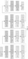
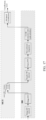
- the process of target detection is shown in FIG. 1 .
- a main control module for example, it may be implemented based on a microcontroller unit (MCU) or the like
- BB baseband
- range dimension direct current removal Range DC removal
- Range FFT range-dimension Fourier transform
- the baseband module sends the signal to a main control module for multi-frame integration.
- the main control module transfers the integrated multi-frame data from a static random-access memory (SRAM) of the CPU to the baseband module.
- SRAM static random-access memory
- Doppler DC removal, inter-frame Fourier transform (Frame FFT), inter-channel integration (such as non-coherent integration, and coherent integration) are performed based on the baseband module.
- CFAR detection for example, CFAR detection with peak selection
- angle detection and target classification are performed to obtain range, speed, and/or angle information of the target.
- Range DC removal targets the data corresponding to each chirp in each frame of data.
- Range DC removal specifically includes: calculating the average of the data collected by each receive (RX) channel for each chirp along the fast time domain, and then subtracting the DC component from all sampling points of each RX channel.
- Range FFT may be achieved by windowing the data after Range DC removal and then performing 1D-FFT.
- each chirp data in each frame of data obtained by radar through ADC or sampling based on the echo signal undergoes the aforementioned operations and is then sent to the main control module.
- Sending the data to the main control module may be achieved by transferring the data from direct memory access (DMA) to the SRAM of the CPU.
- DMA direct memory access
- Doppler DC removal may be achieved by calculating a complex average along the frame dimension for multiple frames of data integrated on the main control module (i.e., averaging the data from the same range bin of the same channel across different frames), obtaining the average values for different channels and different ranges as the DC components for the corresponding range bins of the corresponding channels, and subtracting the respective DC component for each range bin of each channel.
- Frame FFT may be achieved by windowing the data after Doppler DC removal along the frame dimension and performing 2D-FFT along the frame dimension.
- the range-Doppler information of each transmitting and receiving channel can be obtained.
- it can be achieved in the following way. After performing range-dimension FFT on the echo signal, the results obtained from the range-dimension FFT are subjected to sliding windowing, and the windowed data is then subjected to 2D FFT (Doppler FFT) to obtain the Range-Doppler map; where the duration of the sliding window corresponding to the same order of magnitude as the period of the target's periodic motion.
- Doppler FFT Doppler FFT
- Angle detection may be achieved by performing azimuth-dimension digital beam-forming (DBF) and DOA, and pitch-dimension DBF and DOA on the target points obtained from CFAR, where DBF and DOA have been described in existing DBF and DOA technologies, and further details are omitted here for brevity.
- DBF digital beam-forming
- DOA pitch-dimension DBF and DOA
- Target classification may be achieved by counting the target points detected in each frame (or preset data amount, i.e., each time) according to a preset (or divided) regional unit design, and determining the counting results according to preset rules to determine whether there are physical targets of interest (such as adults, children, infants, or pets) present in the processing, and to determine their location region.
- preset data amount i.e., each time
- preset rules to determine whether there are physical targets of interest (such as adults, children, infants, or pets) present in the processing, and to determine their location region.
- FIG. 1 serves only as an example. Specifically, frame data integration, target classification (which may be achieved using techniques such as Region HIST and classification), and other operations are performed in the main control module, while other operations, such as Range DC removal and Doppler DC removal, are performed in the baseband module. In other embodiments, frame data integration may be performed in the baseband module, and Doppler DC removal may be performed in the main control module.
- FIG. 1 only 128 frames of data are cached for illustration purposes. In other embodiments, 56 frames of data or 32 frames, etc., may also be cached. This is not limited in the embodiments of the present application and can be determined based on requirements or hardware support capabilities. In this way, the cached multi-frame data will continue to undergo Doppler DC removal and Frame FFT to obtain a range-Doppler (RD) map.
- RD range-Doppler
- the embodiments of the present application further propose processing in combination with a deep learning model.
- Deeply mining target information through a deep learning model can achieve more precise target detection solutions within spatial regions such as automobile cabins, indoor spaces, and industrial plants. These solutions can effectively improve the detection rate, reduce the false alarm rate, and significantly improve the accuracy of angle estimation. Consequently, special or weak targets within the cabin, such as infants, can be accurately detected, enabling applications such as child presence detection (CPD) and safety belt reminder (SBR).
- CPD child presence detection
- SBR safety belt reminder
- deep learning models can be integrated into the aforementioned embodiments in various ways. The following will elaborate on different integration scenarios.
- the method for target detection includes the following steps.
- step 101 FFT and beam-forming are performed on the echo signal to generate a feature vector of the echo signal, where the feature vector includes energy characteristics that represent the echo signal across different range bins.
- step 102 the feature vector is processed based on a deep learning model to achieve target detection in a region of interest.
- beam-forming processing can effectively improve the signal-to-noise ratio of human targets to static strong clutters, enable the construction of feature vectors for empty vehicles (with or without interference), adult presence scenarios, and child presence scenarios.
- Deeply mining target information contained in these feature vectors through a deep learning model can achieve more precise target detection solutions within spatial regions such as automobile cabins, indoor spaces, and industrial plants. These solutions can effectively improve the detection rate, reduce the false alarm rate, and significantly improve the accuracy of angle estimation. Consequently, special or weak targets within the cabin, such as infants, can be accurately detected, enabling applications such as CPD and SBR.
- the deep learning module it is also possible to reduce the amount of digital signal processing required. For example, after extracting features, there is no need to perform CFAR, DOA, and other processing.
- step 101 the implementation of FFT and beam-forming is not limited. It is conceivable that since beam-forming processing essentially focuses the directional gain (which reflects energy) of the signal in a specified direction, beam-forming actually extracts energy characteristics. In other words, different implementations of FFT and beam-forming do not affect the extraction of energy characteristics, and consequently not affect the generation of the feature vector that represent the energy characteristics of the echo signal across different range bins.
- the target detection process involves beam-forming processing to achieve angle estimation, and subsequent processing such as target classification is also required to output intuitive and accurate results.
- beam-forming is used to generate a feature vector
- subsequent angle estimation, target classification, etc. can be replaced by deep learning model processing, which is more efficient.
- the deep learning model does not directly use time-series data as input, but further extracts target information from echo signals through FFT and beam-forming, forming a feature vector with higher dimensions and richer information, which enables the deep learning model to better analyze and process, output more accurate results, improve the accuracy and efficiency of target detection, and achieve more accurate in-cabin target detection and recognition. Due to the fact that noise and target reflection signals possess distinct energy characteristics, using a feature vector that represents the energy characteristics can facilitate target detection with the deep learning model, outputting more accurate and reliable results.
- the application of the deep learning model is to replace processes such as CFAR and angle estimation and directly output detection results. That is to say, based on the process shown in FIG. 1 , beam-forming is performed after Frame FFT, and the processing with deep learning model replaces coherent integration, CFAR, angle estimation, and other processes.
- FFT and beam-forming performed on the echo signal can be achieved through the following steps.
- step 1011 FFT is performed on the echo signal to generate a Range-Doppler map.
- step 1012 beam-forming is performed based on the Range-Doppler map.
- FFT includes Range FFT and Frame FFT. After the Range FFT, beam-forming can be achieved without waiting for Frame FFT. Furthermore, as mentioned earlier, even if the implementation sequence of beam-forming varies, energy characteristics can still be obtained, and the feature vector can still be generated. Therefore, in some embodiments, as shown in FIG. 4 , FFT and beam-forming performed on the echo signal can also be achieved through the following steps.
- step 1013 Range FFT is performed on the echo signal.
- step 1014 beam-forming is performed on the results from Range FFT.
- step 1015 sliding windowing is performed on the results of beam-forming, and 2D FFT is performed on the windowed data.
- the 2D-FFT herein may also adopt the sliding window 2D-FFT.
- FFT and beam-forming performed on the echo signal can also be achieved through the following steps.
- step 1016 Range FFT is performed on the echo signal.
- step 1017 beam-forming is performed on the results from Range FFT.
- beam-forming is performed based on the results of Range FFT
- beam-forming is performed based on the results of Frame FFT. Therefore, the implementation methods of beam-forming will also vary. Specifically, in the embodiments shown in FIG. 4 and FIG. 5 , beam-forming is achieved in the range dimension, that is, synthesis and integration are performed on different range bins. In the embodiment shown in FIG. 3 , beam-forming can be achieved in both the range dimension and the Doppler dimension, that is, synthesis and integration are performed on different Doppler bins of different range bins. To facilitate understanding, the following explanation will be based on the implementation of beam-forming in the embodiment shown in FIG. 3 by way of example.
- P ( r,v,b ) represents the energy characteristics of the v Doppler bin of the r range bin based on beam b
- sv ( c, b ) represents a steering vector of beam b in virtual channel c
- x ( c, r, v ) represents the corresponding data of the v Doppler bin of the r range bin in virtual channel c in the Range-Doppler map
- N c represents the total number of beams.
- x ( c,r,v ) in the above expression is replaced with x ( c, r ) which does not include the Doppler dimension.
- beam-forming can be implemented through other methods. Further details are omitted here for brevity.
- the steering vector may be specified by the user, or be automatically generated based on the region of interest.
- beam-forming can be achieved in the following way. determining a target direction pointing to the region of interest and generating a steering vector based on the target direction; and performing beam-forming based on the steering vector.
- the determination of the target direction is also not limited in the embodiments of the present application.
- determining the target direction pointing to the region of interest includes: determining the target direction based on an azimuth and an elevation of the region of interest relative to the radar.
- determining the target direction pointing to the region of interest includes: obtaining actual measurement data of the target in the region of interest; and clustering the actual measurement data of the target, and taking the azimuth and the elevation of a cluster center within the regions of interest as the target direction.
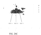
- the scenario requirements involve determining whether there is a person present in six regions in the vehicle: three rear seats and three aisles in front of the three seats. If present, it further determines whether it is an adult or a child.
- a 6-point DBF can be implemented, which involves determining six target directions respectively pointing to the three seats and the three aisles shown in FIG. 6 . Consequently, P ( r,v,b ) corresponding to six beams are obtained.
- other directions can also be added, such as adding three auxiliary beams pointing to three other regions.
- a 9-point DBF can be implemented to obtain P ( r, v, b ) corresponding to nine beams.
- sv c b exp 1 j ⁇ 2 ⁇ / ⁇ ⁇ x c cos ⁇ b sin ⁇ b + z c sin ⁇ b
- sv ( c,b ) represents the steering vector of beam b in virtual channel c
- ⁇ represents the central wavelength of the radar detection signal
- x c and z c respectively represent the horizontal and vertical positions of the antenna corresponding to the virtual channel c
- ⁇ b represents the azimuth corresponding to the target direction
- ⁇ b represents the elevation corresponding to the target direction.
- target detection since the coverage of radar is generally larger than the range required by users for target detection, target detection generally occurs within the regions of interest of the users. Based on this, in the embodiments of the present application, target detection in regions of interest is primarily illustrated by way of example. However, this does not imply that the method for target detection provided by the embodiments of the present application is solely applicable to regions of interest. For instance, it can also be applied to all detectable regions, which is not further elaborated herein or in subsequent sections.
- the input of a deep learning model can affect its accuracy.
- the energy characteristics in the feature vector can be particularly arranged.
- generating the feature vector of the echo signal can be achieved in the following way: rearranging, according to preset rules, the energy characteristics obtained from FFT and beam-forming performed on the echo signal to obtain the feature vector. Such rearrangement can enhance the correlation of data in the feature vector, which is beneficial for the model to perform better detection.
- the embodiments of the present application do not limit the specific rules for rearrangement.
- the preset rules include: data with the same first dimension is continuously arranged according to a progression direction of the second dimension, and the overall arrangement follows a progression direction of the first dimension, where the first and second dimensions refer to different dimensions in the beam and range dimensions, respectively. This rule corresponds to the situation where energy characteristics are generated only in the range dimension.
- the preset rules include: data with the same third dimension and the same fourth dimension is continuously arranged according to a progression direction of the fifth dimension, data with the same third dimension is continuously arranged according to a progression direction of the fourth dimension, and the overall arrangement follows the progression direction of the third dimension, where the third, fourth, and fifth dimensions correspond to different dimensions in the beam, range, and Doppler dimensions, respectively.
- This rule corresponds to the situation where energy characteristics are generated in both range and Doppler dimensions.
- the energy characteristics are arranged continuously in physical memory along the v dimension, followed by the r dimension, and finally the b dimension.
- v(0) and v(Nv) represent the 0th and Nvth Doppler bins (Nv+1 Doppler bins in total)
- r(0) and r(Nr) represent the 0th and Nrth range bins (Nr+1 range bins in total)
- b0 represents the 0th beam (N beams in total).
- the array consisting of (Nv+1) ⁇ (Nr+1) ⁇ N energy characteristics is the feature vector input to the deep learning model.
- target detection is implemented based on hardware. Therefore, in order to adapt to the capability of the hardware, data processing can also be performed to accommodate the capability of the hardware.
- generating the feature vector of the echo signal can be achieved in the following way: performing logarithmic normalization on the energy characteristics obtained from FFT and beam-forming performed on the echo signal.
- logarithmic normalization the data is converted from floating-point numbers to fixed-point numbers, which is beneficial for improving the efficiency of subsequent processing, thereby enhancing the efficiency of target detection.
- performing logarithmic normalization on the energy characteristics obtained from FFT and beam-forming performed on the echo signal can also be achieved in the following way: logarithmically transforming the energy characteristics obtained from FFT and beam-forming performed on the echo signal, and linearly normalizing the logarithmically transformed results by using preset upper and lower bound constraints. Based on the logarithmic normalization, upper and lower bounds as well as linear parameters are further introduced, so that the data format is further optimized, which is more beneficial for forming feature data for subsequent use.
- P norm (r, v, b) represents the logarithmic normalization result
- P ( r,v,b ) represents the energy characteristic of beam b at the range bin r and the Doppler bin v
- a 0 , b 0 , P max , and P min are all preset parameters.
- b 0 may be set as the mean or median of all possible values of log 2 (P(r, v, b )).
- a 0 may be set as the difference between the 95% quantile and the 5% quantile of all possible values of log 2 (P(r, v, b )), divided by 256. This can normalize P norm ( r , v, b ) to a range of -127 to 127, which is the range of fixed-point numbers.
- the normalization embodiments provided in the aforementioned embodiments may be implemented using various forms.
- the normalization may be implemented in MCU after complex data is transferred to Mem of MCU via DMA.
- the normalization may be implemented using a hardware engine in BB and then directly transferred to Mem of MCU via DMA.
- a portion of the normalization may be implemented in BB, and the remaining calculations are performed in the MCU after transferred to Mem of MCU via DMA.
- modulo square operation and taking logarithms with 2 as the base can be implemented in BB, and subtraction, division, and saturation truncation can be implemented in MCU. Further details are omitted here for brevity.
- step 102 what kind of deep learning model is used is not limited. It can be any deep learning model, such as convolutional neural networks (CNN) or Transformer. Further details are omitted here for brevity.
- CNN convolutional neural networks
- Transformer Further details are omitted here for brevity.
- processing procedure and result output of the deep learning model can be adjusted through the structural setting of the deep learning model and the training of the model.
- the target detection result is a confidence matrix where the elements correspondingly indicate at least one of the following items of information: confidence level of detecting the presence of target, confidence level of the presence of target within the corresponding region of interest, confidence level of the presence of an adult target within the corresponding region of interest, and confidence level of the presence of a child target within the corresponding region of interest.
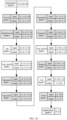
- the structure of the deep learning model is a CNN with 3 convolutional kernels, and the type, input, and output sizes of each layer are shown in FIG. 8 .
- the dimension of input features of the deep learning model is 6 ⁇ 64 ⁇ 20, corresponding to 6 beam directions, 64 Doppler bins, and 20 range bins.
- Each convolution operation includes a two-dimensional convolution layer, a batch normalization layer, a ReLu nonlinear activation layer, and a max pooling layer. After performing 3 times of convolution operations, the resulting feature vector of 128 ⁇ 2 is flattened into a one-dimensional feature vector of 256 ⁇ 1. After random dropout, the vector passes through a fully connected layer of 256 ⁇ 10 to obtain the detection results (for example, whether there is a person inside the vehicle, and confidence level of the presence of adults or children on each seat and aisle inside the vehicle.
- the method before processing the feature vector based on the trained deep learning model to obtain the target detection results output by the deep learning model, the method further includes the following steps.
- step 103 the training feature vector is obtained, where the training feature vector carries one-hot encoded labels and is used to represent the energy characteristics of the signal across different range bins.
- the training feature vector is processed using a preset data augmentation method to obtain a training set.
- the preset data augmentation method includes at least one of the following: randomly adding white noise, flipping the data along Doppler dimension, and shifting the data along range dimension.
- step 105 the deep learning model is trained based on the training set.
- training feature vectors are obtained according to the aforementioned method of obtaining the feature vector, and multiple sets of processed data from multiple experiments are integrated to construct an input feature dataset S ⁇ P ⁇ , where each element P i is the aforementioned (Nv + 1) ⁇ (Nr + 1) ⁇ N array.
- ⁇ ⁇ is labeled according to the experimental conditions, meaning that corresponding label L i is generated for P i , obtaining a labeled input feature dataset ⁇ , ⁇ .
- one-hot encoding can be used to generate the label L i . Taking the interior scene shown in FIG.
- L i is a 1 ⁇ 10 vector with values of 0 or 1.
- the first bit of L i indicates whether there is a person inside the vehicle. If there is no person, this bit is 1; and if there is a person, this bit is 0.
- the 2nd to 4th bits indicate whether there is a child on seat A to seat C. If there is a child, the corresponding bit is 1; and if not, the corresponding bit is 0.
- the 5nd to 7th bits indicate whether there is a child on aisle A to aisle C.
- the corresponding bit is 1; and if not, the corresponding bit is 0.
- the 8nd to 10th bits indicate whether there is an adult on seat A to seat C. If there is an adult, the corresponding bit is 1; and if not, the corresponding bit is 0. If there is no person inside the vehicle, then the corresponding L i is [1, 0, 0, 0, 0, 0, 0, 0, 0]. If there is an adult on seat A in the vehicle, the corresponding L i is [0, 0, 0, 0, 0, 0, 0, 1, 0, 0]. If there is a child on aisle A and an adult on seat B in the vehicle, the corresponding L i is [0, 0, 0, 0, 1, 0, 0, 0, 1, 0].
- L i can be a 1 ⁇ 9 vector. When all its elements are zero, it indicates that there is no person inside the vehicle.
- one or more methods such as randomly adding white noise to ⁇ , ⁇ , randomly flipping the data along Doppler dimension, and randomly slightly shifting the data along range dimension, are applied to augment the data, obtaining an augmented dataset .
- the sample size of the augmented dataset is significantly increased compared to the original dataset.
- ⁇ , ⁇ there are 5000 samples each for empty vehicle, child presence, and adult presence.
- the deep learning model is trained in the following way:
- Adam Optimizer can be used as the gradient descent optimizer, and cross entropy can be selected as the loss function.
- sigmoid normalization should be applied before using cross entropy for loss calculation.
- the learning rate is set to 0.001
- the weight decay is set to 0.0001
- N s is set to 128, and N es is set to 5.
- the feature vector is used to represent the energy characteristics of the echo signal across different range bins within a preset Range bin index range and/or preset Doppler bin index range. For example, when performing beam-forming, only data from some Doppler bins and range bins are used, such as the 0-32 and 96-127 Doppler bins, and the 10-42 range bins. This approach retains only the parts that are of interest to the user, thereby reducing the occupation of computational and storage resources and improving detection efficiency.
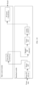
- the embodiment shown in FIG. 3 is as shown in FIG. 10 after being applied in the complete target detection process. That is, based on the process shown in FIG. 1 , after Frame FFT, two-dimensional digital beam-forming (2D-DBF) and DL-based classification are directly performed. That is, instead of performing CFAR after Frame FFT, 2D-DBF are performed on the azimuth and pitch dimensions for each region of interest (or unit zone) to obtain the corresponding number of RD maps to the regions of interest. Subsequently, the aforementioned RD maps are input into the constructed deep learning (DL) model for target determination.
- the relationship between the aforementioned regions of interest and the RD maps may also be one-to-many, meaning that at least two RD maps can be derived from a single region of interest. The specific number can be adjusted based on actual needs.
- the aforementioned DL input can be the amplitude or power in linear or dB domain, and can undergo normalization and other operations.
- the constructed deep learning model can classify based on the input, and the categories it can classify into are: whether there are objectives, the attributes of the objectives, and the specific unit zone position (i.e., regional locations) where each objective is located.
- the center positions of the aforementioned six regions of interest can undergo 2D-DBF in azimuth and pitch dimensions to obtain six RD maps (or three RD maps) corresponding to the regions of interest.
- At least some regions of the aforementioned six RD maps (or three RD maps) are input into the constructed deep learning model for target determination and identification.
- the constructed deep learning model classifies based on the input to determine whether there is a living target in the aforementioned regions of interest. If there is a living target, it can further determine whether the living target is an adult, child, infant, pet, etc., and can further determine the specific location information such as which seat or aisle region the living target is in.
- the method for target detection is a model-data dual-driven processing flow. It has relatively low requirements for signal processing and can effectively avoid steps such as the selection of signal processing parameters and region parameters, and the design of CFAR logic and region determination logic, thereby significantly reducing the difficulty of scheme implementation and design.
- the embodiment shown in FIG. 4 is as shown in FIG. 11 after being applied in the complete target detection process.
- FIG. 11 based on the process shown in FIG. 1 , after Range FFT (also known as 1D-FFT), 2D-DBF is performed first, and the frame data integration and Frame FFT are then performed. That is, before performing Frame FFT, the center positions of the regions of interest (such as the three seat regions) undergo 2D-DBF in azimuth and elevation dimensions.
- Range FFT also known as 1D-FFT
- 2D-DBF is performed first, and the frame data integration and Frame FFT are then performed. That is, before performing Frame FFT, the center positions of the regions of interest (such as the three seat regions) undergo 2D-DBF in azimuth and elevation dimensions.
- This embodiment enables a parallel processing scheme for data processing and wave transmission time, thereby effectively reducing processing time.
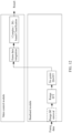
- the embodiment shown in FIG. 5 is as shown in FIG. 12 after being applied in the complete target detection process.
- FIG. 12 based on the process shown in FIG. 1 , after Range FFT (also known as 1D-FFT), 2D-DBF is performed to achieve the frame data integration, and complex DL-based classification is directly performed. That is, in the entire target detection process, Frame FFT is not performed.
- 1D-FFT the center positions of the regions of interest (such as the three seat regions) directly undergo 2D-DBF to obtain the corresponding number of range-frame maps (such as three range-frame maps), and then the above range-frame maps are input into the constructed (for example, complex) deep learning model for target identification and determination.
- the embodiment shown in FIG. 12 can effectively reduce the computational load by avoiding Frame FFT. Moreover, if a complex deep learning model is utilized, higher processing gains compared to FFT can be achieved, thereby enhancing the performance of target detection. In addition, this embodiment effectively shortens the processing hierarchy, facilitating efficient scheduling operations therefor.
- combining 2D-FFT with DL-based classification can effectively enhance the accuracy of target identification.
- the steps of 2D-FFT and DL-based classification can be flexibly arranged between various steps in signal processing according to actual needs.
- the steps of 2D-FFT may be arranged after Range FFT or Frame FFT.
- all FFT processes may be windowed FFT, and may also be implemented using SVA combined with FFT.
- multi-frame sliding window FFT may be replaced with other time-frequency transformation processes, such as short-time Fourier transform and fractional Fourier transform, which can also achieve effective detection of the target of interest.
- multi-frame sliding window FFT may be replaced with high-pass FIR, Comb FIR, or a filter optimized based on an optimization function, thereby achieving similar or even higher performance with fewer hardware resources compared to multi-frame FFT.
- DBF may be replaced with algorithms such as Capon, MUSIC, ESPRIT, and their variants.
- beam-forming at the center of the region of interest can be optimized and/or antenna arrangement can be optimized to further enhance the performance of target detection of the system.
- FIG. 10 to FIG. 12 are merely schemes for target detection in combination with multi-frame integration technology. However, this does not imply that multi-frame integration is necessarily combined. For instance, in the embodiment shown in FIG. 12 , inter-frame integration is omitted. Of course, there are other examples, and further details are omitted here for brevity.
- the embodiments of the present application also provide another method for target detection.
- coherent integration is performed for the frequency of human respiration, thereby improving the signal-to-noise ratio of human targets to static strong clutters and effectively constructing feature data for empty vehicle (with or without interference), adult presence scenarios, and child presence scenarios.
- deep learning models deep information mining can be performed on the constructed feature data, thereby achieving effective detection of whether there is a person inside the vehicle and accurate determination of adults and children. This can enable more accurate detection and identification of targets in spatial regions such as automobile cabins, indoor spaces, and industrial plants.
- the method for target detection includes the following steps.
- DC removal is performed for each chirp data in each frame.
- DC removal can be performed on the downlink ADC data in BB.
- it includes: calculating the average of the data collected by each receive (RX) channel for each chirp along the fast time domain, and then subtracting the DC component from all sampling points of each RX channel; then windowing the data after DC removal, and subsequently performing 1D-FFT to obtain range dimension information, then transferring the 1D-FFT data is transferred from BB to SRAM of CPU for cache via DMA; and finally performing the same operations mentioned above for different chirps.
- step S12 when the data cached in the SRAM of CPU reaches a certain number of frames, such as 128 frames, the 128 frames of data are transferred from the SRAM of CPU to BB via DMA, and the following steps are executed.
- DC removal is performed on multi-frame 1D data: calculating the complex average along the frame dimension for these 128 frames of data, obtaining the average values for different channels and different ranges as their DC components, and then subtracting the DC component from each channel and each range bin.
- the data after DC removal is windowed along the frame dimension, and 2D-FFT calculation is performed along the frame dimension, to obtain the range-Doppler complex value x(c, r, v) of each transmitting and receiving channel.
- Doppler bins and range bins are selected, such as selecting the 0-32 and 96-127 Doppler bins, and 10-42 range bins.
- the energy of the complex value x(c,r,v) for each range bin and each Doppler bin in each channel is calculated, then log operation and normalization are performed thereon.
- P c r v P max , log 2 x c r v 2 ⁇ b 0 a 0 , P min , log 2 x c r v 2 ⁇ b 0 a 0 ⁇ P max P min ⁇ log 2 x c r v 2 ⁇ b 0 a 0 ⁇ P max log 2 x c r v 2 ⁇ b 0 a 0 ⁇ P min
- P(c,r,v) represents the normalized "energy" of the virtual channel c at the range bin r and the Doppler bin v, b 0 and a 0 are preset normalization parameters, while P max and P min are preset upper and lower limits for P(c,r,v).
- b 0 may be set as the mean or median of all possible values of log 2 (
- a 0 may be set as the difference between the 95% quantile and the 5% quantile of all possible values of log 2 (
- v(0) and v(Nv) represent the 0th and Nvth Doppler bins (Nv+1 Doppler bins in total)
- r(0) and r(Nr) represent the 0th and Nrth range bins (Nr+1 range bins in total)
- c0 represents the 0th virtual channel (Nc+1 virtual channels in total).
- the array consisting of (Nv + 1) ⁇ (Nr + 1) ⁇ (Nc + 1) elements is the input feature data for the deep learning model.
- the aforementioned data is fed into the constructed deep learning model to determine whether there is a person inside the cabin and whether it is an adult or a child, and the results are outputted.
- the deep learning model may be either a CNN or a Transformer.
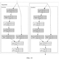
- An embodiment of the construction process of this model is shown in FIG. 14 , including the following steps.
- step S21 the input feature data is obtained from the same steps as described above, multiple sets of processed data from multiple experiments are integrated to construct an input feature dataset S ⁇ P ⁇ , where each element P i is a (Nv + 1) ⁇ (Nr + 1) ⁇ (Nc + 1) array as defined in the above step 2.c.
- step S22 ⁇ ⁇ is labeled according to the experimental conditions, meaning that corresponding label L i is generated for P i , obtaining a labeled input feature dataset ⁇ , ⁇ .
- step S23 one or more methods, such as randomly adding white noise to ⁇ , ⁇ , randomly flipping the data along Doppler dimension, and randomly slightly shifting the data along range dimension, are applied to augment the data, obtaining an augmented dataset ⁇ , ⁇ ⁇ .
- the sample size of the augmented dataset is significantly increased compared to the original dataset. For example, in ⁇ , ⁇ , there are 5000 samples each for empty vehicle, child presence, and adult presence. These samples can undergo 10 rounds of data augmentation to obtain an augmented dataset ⁇ , ⁇ with 50000 samples for each category (which can optionally include or exclude the original dataset ⁇ , ⁇ ).
- step S25 the deep learning model is trained based on ⁇ , ⁇ and ⁇ , ⁇ .
- the main steps of one embodiment are as follows.
- Adam Optimizer can be used as the gradient descent optimizer, and cross entropy can be selected as the loss function.
- the learning rate is set to 0.001
- the weight decay is set to 0.0001
- N s is set to 128, and N es is set to 5.
- a possible CNN structure is as follows. Shown is a CNN with 3 convolutional kernels, and the type, input and output sizes of each layer are also shown in the diagram. As shown in the diagram, the dimension of input features is 16 ⁇ 64 ⁇ 20, corresponding to 16 beam directions, 64 Doppler bins, and 20 range bins.
- Each convolution operation includes a two-dimensional convolution layer, a batch normalization layer, a ReLu nonlinear activation layer, and a max pooling layer. After performing 3 times of convolution operations, the resulting feature vector of 128 ⁇ 2 is flattened into a one-dimensional feature vector of 256 ⁇ 1.
- the vector After random dropout, the vector passes through a fully connected layer of 256 ⁇ 3 to obtain three types of confidence levels: empty vehicle, child presence, and adult presence.
- the maximum value of the confidence levels can be obtained from softmax calculation, which serves as a classification for the input, determining whether it belongs to the category of empty vehicle, child presence, and adult presence.
- the method for target detection in the embodiments of the present application can also adopt the processing flow shown in FIG. 16 , that is, the data after Frame FFT is non-coherently integrated by channel to obtain an array, and after performing similar operations to the aforementioned steps of extracting partial Doppler bins and range bins, the array is used as input feature data and fed into a deep learning model for processing to obtain classification results; the number of input channels for the deep learning model is correspondingly selected as 1.
- the method for target detection in the embodiments of the present application can also adopt the processing flow shown in FIG. 17 .
- the two-dimensional data obtained by non-coherent integration of data after Frame FFT by channel is further processed by selecting only the energy of points that exceed a set threshold using CFAR.
- the input feature data is obtained by performing similar operations of extracting partial Doppler bins and range bins. The range bins and Doppler bins that do not exceed the threshold are filled in.
- the input feature data is fed into a deep learning model for processing to obtain classification results; the number of input channels for the deep learning model is correspondingly selected as 1.
- CFAR is performed on the data after Frame FFT by channel, only the energy of points that exceed a set threshold is selected for each channel, and the input feature data is obtained by performing similar operations of extracting partial Doppler bins and range bins. The range bins and Doppler bins that do not exceed the threshold are filled in. Subsequently, the data from all channels is rearranged in a similar manner to the aforementioned rearrangement of P ( c,r,v ) as input feature data, and is fed into the deep learning model for processing to obtain classification results; the number of input channels for the deep learning model should be correspondingly selected as the number of virtual channels used.
- the deep learning model in the embodiments of the present application may choose other CNNs or Transformers, as long as they are compatible with its input.
- the CNN model modified based on ResNet18 and the expansion of the Sequential module within it can be utilized.
- the output here can also be categorized into two types: empty vehicle and non-empty vehicle.
- the two images in FIG. 20 respectively show an example of CNN input feature maps corresponding to adults and children.
- the left image shows the input features of an adult, while the right image shows the input features of a child.
- Each sub-image corresponds to the data of each channel.
- the horizontal axis represents Doppler bins, and the vertical axis represents range bins. In this example, 20 range bins and 64 Doppler bins are extracted.
- FIG. 21 illustrates the variations in model loss and classification accuracy as the number of training epochs increases. It can be seen that the model converges after approximately 7 epochs and achieves an accuracy of 98%.
- FIG. 22 displays the confidence levels achieved during testing on both adult and child samples.
- the horizontal axis represents the sample serial number, and the vertical axis represents the confidence level (i.e., score).
- the first 150 samples are of adult inside the car
- the last 150 samples are of child inside the car.
- a potential deep learning model calculates the confidence levels for both adults and children, resulting in two points, blue and orange, for each sample.
- the confidence level of an adult is higher than that of a child, it is determined that the person inside the vehicle is an adult.
- the confidence level of a child is higher than that of an adult, it is determined that the person inside the vehicle is a child.
- the trained CNN model can correctly determine whether the person inside the car is an adult or a child.
- the method for target detection includes the following steps.
- step 10 after performing Range FFT on the echo signal, 1D-FFT data is obtained.
- step 20 digital beam-forming is performed on the 1D-FFT data to obtain a preset number of frame data.
- step 30 target classification processing is performed on the preset number of frame data using a machine learning model to achieve target detection.
- the detection of targets in the regions of interest mentioned above includes at least one of the following operations: determination, localization, identification.
- the method in this embodiment has lower requirements for processing units (such as BB units), utilizes data with higher dimensionality and richer information, and can achieve more accurate in-cabin target detection and identification, enabling applications such as CPD and SBR.
- processing units such as BB units
- the machine learning model may be a complex machine learning model, such as a complex-valued neural network model.
- the model used in the embodiment shown in FIG. 24 is a machine learning model, while the model used in the aforementioned embodiment is a deep learning model. To accommodate the input of the complex machine learning model, in some embodiments, this can be achieved by transforming the feature vector.
- z real and z img represent the normalized real part and imaginary part, respectively.
- ⁇ (r,v,b) represents the phase of beam b at range r and chirp v
- z(r, v, b) represents the normalized complex signal.
- z(r, v, b) may also be represented using double-precision floating point or single-precision floating point, or quantized in the form of int32, int16, int8, or uint32, uint16, uint8, or through other quantization processes.
- a complex-valued neural network model can remove the absolute value (abs) layer in the last layer of the complex-valued CNN. Under this case, the output of the complex-valued CNN is a complex-valued output.
- Loss CE Re y , t / 2 + CE Im y , t / 2
- y represents the forward computation output of a complex-valued CNN for a certain sample, which is a vector with a length equal to the number of classifications, and y i represents the i scalar in y
- t represents the one-hot encoded label of the sample and also is a vector with a length equal to the number of classifications
- t i represents the i scalar in t.
- Other hyperparameters, such as learning rate and weight decay, may have alternative values.
- FIG. 24 The embodiment shown in FIG. 24 is basically the same as the other features or implementation methods of the aforementioned embodiments, and further details are omitted here for brevity.
- the corresponding digital signal processing processes are replaced through the use of models, such as replacing angle estimation, CFAR, and other processes.
- the model can also be utilized to further process the targets obtained from digital signal processing.
- the method for target detection includes the following steps.
- step 30 after performing Range FFT on the echo signal, 1D-FFT data is obtained. This 1D-FFT data is then subjected to multi-frame joint processing to obtain the RD map.
- step 40 target point cloud data is obtained based on the RD map, and target classification based on machine learning is performed on the target point cloud data to achieve the detection of targets in the regions of interest.
- the detection of targets in the regions of interest mentioned above includes at least one of the following operations: determination, localization, identification.
- the method for target detection and its related device can achieve target detection solutions in enclosed spaces such as cabins, indoor regions, and industrial buildings through multi-frame joint processing technology, namely through inter-frame integration.
- This can effectively improve detection rates, reduce the false alarm rate, and significantly enhance the accuracy of angle estimation, thereby enabling precise detection of special or weak targets such as infants in cabins, and realizing applications such as CPD and SBR.
- target classification based on machine learning on point cloud data more precise region determination and more accurate identification of targets within the region can be achieved. For example, it can improve the accuracy of determining the presence and location of persons in enclosed environments such as cabins.
- the aforementioned step 30 includes: obtaining 1D-FFT data after performing Range FFT on the echo signal in the chirp domain; performing frame data integration on the 1D-FFT data until the integration reaches a preset data amount, and then performing Frame FFT to obtain the RD map.
- a sliding window approach may be adopted to read 1D-FFT data of a preset number of frames each time for Frame FFT. That is, precise detection of targets within the cabin can be achieved based on multi-frame joint processing technology.
- the multi-frame joint processing scheme may be, after obtaining a Range-Doppler map through sliding window FFT on multi-frame data, or after using finite impulse response (FIR) or other complex time-frequency transformation processing, performing CFAR, DOA, and other processing operations on the regions of interest, and combining the set region determination logic and region parameters to achieve the detection and localization of living targets such as adults, children, pets, or other non-living targets.
- CFAR may be NR-CFAR in Doppler dimension, RD-CFAR, Doppler-azimuth-pitch (DAE) -CFAR, etc.
- DAE Doppler-azimuth-pitch
- post-processing techniques such as clustering, false alarm suppression, and multiple processing point cloud association may be applied.
- the region parameters may be determined by adopting at least one or a combination of at least two of clustering the point cloud detected after multi-frame processing of a sliding window, and detecting and removing outliers from the point cloud detected after multi-frame processing of
- obtaining target point cloud data in the aforementioned step 40 includes: performing non-coherent integration on the RD map of each channel, performing noise-estimation-based CFAR based on the non-coherent integration results to obtain candidate target detection points, estimating the azimuth mid-angle and elevation for the candidate target detection points, and obtain the target point cloud data based on the azimuth mid-angle and elevation.
- Performing non-coherent integration on the RD map of each channel can effectively improve the signal-to-noise ratio of human targets to static strong clutters.
- CFAR includes: performing non-coherent integration on the RD map of each channel, estimating the noise floor of each range bin after non-coherent integration, obtaining a noise floor estimation value for each range bin, and performing non-coherent CFAR with the noise floor estimation value, where when estimating the noise floor of each range bin after non-coherent integration, the noise floor of each range bin is corrected with a global noise floor.
- the correction method includes the following.
- step 40 performing target classification based on machine learning on the target point cloud data to achieve the detection (i.e., determination) of targets in the regions of interest includes: inputting the target point cloud data into a pre-trained first machine learning classifier to obtain a first detection result indicating whether the candidate target detection point is a valid candidate target detection point, where the target point cloud data includes coordinate data.
- the coordinate data referred to refers to the coordinates of a Cartesian coordinate system, including x-coordinate, y-coordinate, and z-coordinate.
- the data input to the first machine learning classifier further includes one or more of the following: range data, signal-to-noise ratio, amplitude, azimuth mid-angle, and elevation.
- step 40 performing target classification based on machine learning on the target point cloud data to achieve the detection (i.e., localization and identification) of targets in the regions of interest includes: processing the target point cloud data, extracting regional information of the candidate target detection points, and inputting the regional information into a pre-trained second machine learning classifier to obtain a second detection result indicating whether there is a target in the preset region.
- the regional information of the candidate target detection points includes one or more of the following types of information: the number of valid candidate target detection points in each preset region, the proportion of valid candidate target detection points in each preset region to the total valid candidate target detection points, and the mean and variance of the distance, azimuth mid-angle, elevation, and CFAR signal-to-noise ratio of all valid candidate target detection points in each preset region.
- Combining machine learning classifiers for classification and/or identification can achieve a more refined regional division than the preset logic can achieve, enabling accurate classification of the corresponding positions in the radar-processed point clouds.
- the first machine learning classifier or the second machine learning classifier may be any one or more of the following classifiers: support vector machine, random forest, decision tree, Gaussian Mixture Model, KNN, hidden Markov, and multilayer perceptron.
- the radar-monitored region can be divided into seating zones and aisle zones. Subsequently, corresponding parameter types and thresholds can be preset for different types of zones, and combined with corresponding processing steps to achieve precise detection of targets of interest in specific regions.
- the interior space can generally be simply divided into head space, rear space, and trunk space. If the rear space is the key monitoring region, it can be further divided into seat regions and aisle regions. The seat regions can also be divided into corresponding number of seat region units based on the seats. Similarly, the aisle regions can also be divided into corresponding number of aisle region units based on the aforementioned seat region units. For example, for a five-seater household sedan, the three seats in the rear space can be divided into three seat region units and three corresponding aisle region units.
- corresponding parameter types and thresholds can be preset, and adaptive signal data processing methods and steps are adopted, in order to achieve accurate detection of the target of interest (specific target) in specific regions such as zones or zone units.
- Adjacent zone units may have partially overlapping regions, or may be adjacent or separated by a gap of a preset width.
- Frame FFT Based on the technical idea of Frame FFT, the technical solution of the present disclosure is described in detail with reference to the accompanying drawings. Specifically, after performing a fast time domain FFT on the chirp in the echo signal, at least two frames of fast time domain FFT data are integrated. Then, Frame FFT is performed on the data of at least two frames to obtain a Range-Doppler (RD) map. Based on this RD map, target distance and/or speed estimation operations are performed.
- RD Range-Doppler
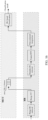
- Range DC removal As shown in FIG. 26A , after performing operations such as ADC (Analog-to-Digital Conversion) and sampling on the echo signal, the following steps are carried out in sequence: Range DC removal, Range FFT (also known as 1D-FFT or fast time domain FFT), multi-frame integration (e.g., storing 128 frames of data), Doppler DC removal, Frame FFT, Non-coherent integration, and then CFAR detection based on the noise obtained from noise estimation (such as using a noise variance estimator). Finally, angle detection and target classification are performed to obtain distance, speed, and/or angle information of the target. For instance, azimuth and elevation estimations can be conducted based on CFAR results, which can be specifically achieved through technologies such as DBF and DoA.
- Range DC removal also known as 1D-FFT or fast time domain FFT
- multi-frame integration e.g., storing 128 frames of data
- Doppler DC removal e.g., storing 128 frames of data
- Frame FFT
- a machine learning model can be integrated to process the output target point cloud data, enabling precise target detection in the regions of interest.
- ML Machine Learning, such as SVM or RF algorithms
- false alarm suppression techniques to suppress non-ideal data such as noise, static clutters, or false alarms caused by target multipath.
- target point cloud data such as elevation DBF & DoA outputs
- one or more of the following operations can be performed: ML-based false-alarm suppression, clustering, and ML-based classification, where clustering can be implemented using algorithms such as agglomerative clustering or DBSCAN.
- the point cloud data after clustering can also be input into a machine learning model (such as SVM or RF) that has been trained to determine whether there is a person present in the current processing. If there is a person, it can further determine his location and achieve operations such as physical target identification and determination such as adults, children, and infants.
- a machine learning model such as SVM or RF
- the embodiment shown in FIG. 26A can effectively reduce the impact of non-ideal factors such as noise, static clutters, and target multipath, effectively alleviate the difficulty in selecting regional parameters and the difficulty in designing complex region determination logic. This, in turn, enables more effective utilization of point cloud information, especially for applications in complex scenes, achieving better performance in target detection and identification.
- frame data integration store 128 frames
- target classification classification, for example, classification based on Region HIST
- Range DC removal and Doppler DC removal can be performed in the BB module or MCU module.
- DC removal is performed on the downlink ADC data in the BB module by way of example.
- the 1D-FFT data can be cached in the MCU module.
- a preset amount of data such as 128, 56, or 32 frames
- the data cached to the preset number of frames can be subjected to DC removal and frame-level FFT in the frame dimension to obtain an RD map.
- non-coherent integration can be performed on the multi-channel RD map, and a noise variance estimator (NVE) module can be utilized to estimate the noise floor of each range bin in the integrated data.
- NVE noise variance estimator
- noise floor estimation can be conducted based on a preset formula
- subsequent noise reference (NR) - CFAR can be performed based on the noise floor estimation value.
- azimuth dimension DBF and DoA can be performed separately for CFAR detection point data to obtain azimuth and elevation estimation data for each CFAR detection point.
- FIG. 26B is a flowchart illustrating another implementation of target detection based on frame-level FFT in an embodiment of the present application.
- the difference from FIG. 2A lies in the slight variation in subsequent classification based on machine learning.
- For the target point cloud data output by elevation DBF & DoA one or more of the following operations are performed: ML-based points classification, Region feature extraction, and ML-based region classification, where ML-based points classification is used to determine the targets in the region of interest, that is, to classify the target point cloud data and obtain effective target detection points (i.e., the aforementioned valid candidate target detection points);
- Region feature extraction can aid classification, for instance, clustering can enhance classification performance, thereby improving classification accuracy and performance, and ML-based region classification is used to locate and identify targets within the region of interest, that is, to determine whether there are targets within a preset region.
- frame-level FFT is utilized to replace conventional chirp-level Doppler FFT to determine the speed of the target, achieving precise detection of the target of interest.
- sliding window FFT across multiple frames can be utilized to further enhance the update frequency of the results, thereby improving the real-time performance of the system.
- the amount of data processed can be reduced by processing only the range bins and/or Doppler bins of interest.
- background noise estimation taking the minimum value of the estimation of the current range bin and that of the last range bin of interest yields a background noise that is more suitable for application scenarios which are relatively sealed such as vehicle interiors.
- counting the target points detected in each frame according to the preset regional design and determining the counting results according to the preset rules can accurately determine whether there are targets within each preset region.
- FFT may be implemented as windowed FFT, or SVA combined with FFT can be used, or multi-frame sliding window FFT can replace other time-frequency transformation processes, such as short-time Fourier transform and fractional Fourier transform. Effective detection of the target of interest can also be achieved, and further details are omitted here for brevity.
- 2D-DBF and ML-based classification operations can be directly performed. That is, after Frame FFT, CFAR is not performed, but 2D-DBF is performed on the azimuth and elevation for each region of interest (or unit zone) to obtain RD maps of a corresponding number to the regions of interest; Subsequently, the aforementioned RD maps are input into the constructed machine learning (ML) model for target determination.
- ML machine learning
- the aforementioned RD map corresponding to FIR is a one-dimensional map output
- the aforementioned RD map corresponding to STFT time-frequency transform is a three-dimensional map.
- the embodiments of the present application can be mutually referenced and compatible without conflict, and the sequence of various functional modules and whether to set up various functional modules can also be adjusted according to needs.
- the various steps in the method for target detection in the embodiments of the present application can be configured to run in the BB module and/or MCU module based on actual needs and considerations of data processing capabilities and timeliness of system operation.
- the relevant examples in the diagram can serve as references for some of these options.
- multi-frame joint processing technology is used, and coherent integration is performed separately on the frequency corresponding to human breathing in the Doppler domain and on multiple antenna channels at preset azimuth in the spatial domain, effectively enhancing the signal-to-noise ratio of human targets to static strong clutters.
- Combining machine learning models for clustering and classification of radar point clouds can achieve a more refined region determination than the preset logic can achieve, enabling accurate classification of the seats corresponding to the radar-processed point clouds.
- By improving the signal-to-noise ratio, unsupervised clustering self-labeling, and refined machine learning classification it is possible to make more accurate determination on the presence and location of human targets in enclosed environments such as cabins.
- the model construction and processing flow in the method disclosed herein reduces the design of rules, eases the difficulty of parameter adjustment, and enhances the convenience and applicability of the method.
- the embodiments of the present application further provide a method for target detection, which is applied to target detection in specific target regions (such as enclosed or semi-enclosed regions).
- the method includes: inputting the target point cloud data into a pre-trained first machine learning classifier to obtain valid candidate target detection points, extracting the region information of all valid candidate target detection points, and inputting them into a pre-trained second machine learning classifier to obtain target detection results.
- Specific steps may refer to the descriptions in the preceding or following embodiments, and are not repeated here.
- FIG. 26B is implemented in a similar manner to the process of the embodiment shown in FIG. 1 and other figures mentioned earlier. Therefore, the same parts are not repeated here. The following primarily explains different parts.
- the following operations are performed for each candidate target detection point T i : extracting 2D-FFT data corresponding to this detection point, selecting the azimuth-dimension antenna, performing azimuth-dimension DBF based on the azimuth-dimension steering vector to obtain the azimuth-dimension DBF map, where the DBF map displays the variation of signal power or intensity in different directions with frequency, and estimating the azimuth mid-angle ⁇ i,j based on the azimuth-dimension DBF map.
- two-dimension DBF for azimuth and elevation can be directly performed to estimate the azimuth mid-angle and elevation, or other super-resolution algorithms such as the minimum variance unbiased estimation (Capon) algorithm, multiple signal classification (MUSIC) algorithm, etc. can be used to estimate the azimuth mid-angle and elevation.
- Capon minimum variance unbiased estimation
- MUSIC multiple signal classification
- information can be extracted from all candidate target points T i,j,k that meet the detection conditions (such as exceeding the CFAR threshold), including but not limited to the range bin index, Doppler bin index, distance r i,j,k , Doppler frequency f i,j,k , azimuth mid-angle ⁇ i,j,k , elevation ⁇ i,j,k , CFAR SNR snr i,j,k , and amplitude amp i,j,k,c of each channel, where c is the channel index.
- the pre-trained first machine learning classifier is utilized to classify the region to which the candidate target belongs. Specifically, multiple attributes of the candidate target point T i,j,k are taken as inputs, and the first machine learning classifier is employed to classify the region to which each candidate target point belongs, in order to determine whether the candidate target point T i,j,k is a valid target point or an invalid interference point in a certain region.
- a possible input instance for the first machine learning classifier is: r i,j,k , x i,j,k , z i,j,k , y i,j,k , snr i,j,k , amp i,j,k,c .
- the machine learning classifier may be, for example, a support vector machine (SVM) or random forest (RF).
- the first machine learning classifier may have multiple forms, or even be a fusion of multiple forms.
- it may be a fusion of support vector machine, decision tree, and Gaussian Mixture Model.
- a weight is set for the output results of each classifier to obtain the weighted average of all classifiers.
- the weighted average result is then used for another determination to obtain the final decision result.
- the attributes of T i,j,k for the selected candidate target points may be the whole or part of "r i,j,k , x i,j,k , z i,j,k , y i,j,k , f i,j,k , snr i,j,k , amp i,j,k,c ".
- coordinate data the aforementioned x, y, z values
- distance data the aforementioned r
- Doppler frequency the aforementioned f
- signal-to-noise ratio the aforementioned snr
- amplitude value the aforementioned amp
- coordinate data may be replaced with azimuth mid-angle and elevation, or the azimuth mid-angle and elevation data may be inputted into the first machine learning classifier together.
- the pre-trained second machine learning classifier is utilized to classify each region, that is, to extract regional features. counting the number of valid target points in each region and the proportion, denoted as w l , of valid target points to the total valid target points, calculating the mean and variance of the distance, azimuth mid-angle, elevation, and SNR for all valid target points in each region, which are denoted as the mean of distance r l , variance of distance ⁇ r,l , mean of azimuth mid-angle ⁇ l , variance of azimuth mid-angle ⁇ ⁇ ,l , mean of elevation ⁇ l , variance of elevation ⁇ ⁇ ,l , mean of SNR snr l , and variance of SNR ⁇ snr,l , where 1 represents the index of the region; feeding the aforementioned regional features, including w l , r l , ⁇ r,l , ⁇ l , ⁇ ⁇ ,l , ⁇ l ,
- valid points that are determined to belong to multiple regions can be counted repeatedly (suitable for multi-label classification, such as scenarios where there is a person present in both region A and region B), or they can be counted non-repeatedly (suitable for single-label classification).
- the present disclosure does not impose any restrictions on this.
- the second machine learning classifier may have multiple forms, or even be a fusion of multiple forms. For example, it may be a fusion of support vector machine, decision tree, and Gaussian Mixture Model.
- a weight is set for the output results of each classifier to obtain the weighted average of all classifiers. The weighted average result is then used for another determination to obtain the final decision result.
- the input of the second machine learning classifier mentioned above is merely an example.
- the attributes of T_(i,j,k) for the selected candidate target points may be part of "w l , r l , ⁇ r,l , ⁇ l , ⁇ ⁇ ,l , ⁇ l , ⁇ ⁇ ,l , snr l and ⁇ snr,l ".
- those skilled in the art can increase inputs of the second machine learning classifier based on the disclosed concept.
- the first machine learning classifier for determining valid points mentioned above may be any of the following classifiers: support vector machine, random forest, decision tree, Gaussian Mixture Model, K-nearest neighbor (KNN), hidden Markov, and multilayer perceptron.
- the training steps of this classifier model include:
- the aforementioned steps 1 to 10 are applied to obtain the attributes of all candidate target points T i,j,k for each scenario.
- the following options can be selected: all or part of r i,j,k , x i,j,k , z i,j,y , y i,j,k , f i,j,k , snr i,j,k , amp i,j,k,c .
- All regional scenarios, such as the seats A, B, C or aisle regions A, B, C in FIG. 5 are traversed, and the following operations are performed:
- each machine learning classifier model M_(v,l) can determine whether a candidate target point is a valid target point in each of the six regions based on the attributes of the candidate target point, such as the 22 x 1 feature vector composed of r i,j,k , x i,j,k , z i,j,k , y i,j,k , f i,j,k , snr i,j,k , amp i,j,k,c .
- the first machine learning classifier may be a classifier for multi-classification, or a classifier with fewer than the number of regions for hierarchical multi-classification.
- classifier 1 can be designed to implement the classification of seats and aisles
- classifier 2 and classifier 3 can be designed to implement the classification of aisles A, B, C and classification of seats A, B, C, respectively.
- oversampling and/or undersampling operations can be performed during the training of the first machine learning classifier.
- the oversampling refers to balancing the quantity differences between different categories in the dataset by increasing the replication of minority category samples or synthesizing new samples. By increasing data in the minority category samples, the distribution of samples among various categories is more balanced, thereby enhancing the model's learning ability for minority category samples.
- the term "undersampling” refers to balancing an imbalanced dataset by reducing the number of majority category samples, so that the sample sizes between various categories are closer. By removing the majority category samples, the number of samples in each category is approximate, thereby reducing the model's preference for the majority category.
- a candidate target point When utilizing the first machine learning classifier for valid point determination, a candidate target point may be classified as belonging to multiple regions. For instance, if the outputs of classifier models M v,1 and M v,2 are both 1, while the outputs of other classifier models are all 0, then the candidate target point is determined to be a valid target point for both seat A and seat B.
- the second machine learning classifier used to determine whether there is a person in each region may also be any of the following classifiers: SVM, RF, decision tree, Gaussian Mixture Model, KNN, hidden Markov, and multilayer perceptron.
- the training steps of this classifier model include: traversing various regional scenarios, such as seats A, B, C or aisles A, B, C, and performing the following operations:
- each machine learning classifier model M c,l can determine whether there is a person present in region l. If the regional features of a sliding window processing are inputted, and the output of the second machine learning classifier model M c,l is 0, it is determined that there is no person in the region 1, while if the output of the machine learning classifier model M c,l is 1, it is determined that there is a person in the region 1. It is noted that based on this processing flow, it is possible to make determination for scenarios involving multiple people.
- the empty vehicle scenario can be output as a separate category.
- the second machine learning classifier may be a classifier for multi-classification, or a classifier with fewer than the number of regions for hierarchical multi-classification.
- oversampling and/or undersampling operations can be performed during the training of the second machine learning classifier.
- the oversampling refers to balancing the quantity differences between different categories in the dataset by increasing the replication of minority category samples or synthesizing new samples. By increasing data in the minority category samples, the distribution of samples among various categories is more balanced, thereby enhancing the model's learning ability for minority category samples.
- the term "undersampling” refers to balancing an imbalanced dataset by reducing the number of majority category samples, so that the sample sizes between various categories are closer. By removing the majority category samples, the number of samples in each category is approximate, thereby reducing the model's preference for the majority category.
- the method in the embodiments of the present application differs from the slow time processing between chirps in radar signal processing in related technologies.
- the embodiments of the present application can improve the signal-to-noise ratio of human targets to static strong clutters.
- the embodiments of the present application utilize machine learning models for regional division, which offers richer information compared to spatial division and regional determination strategies based on preset rules. Furthermore, it can be fully automated without human intervention, significantly reducing the pressure of parameter tuning.
- the embodiments of the present application are not only applicable to the detection and localization of human targets in vehicles, but also to other similar application scenarios such as indoor human detection and factory human detection.
- the aforementioned operations can be executed in CPU or MCU, or in the baseband unit BB, or partially executed by CPU or MCU and partially executed by BB.
- 1D-FFT, 2D-FFT, CFAR, DBF, and DOA are executed in BB, while target detection and identification are executed in MCU.
- FIG. 26A and FIG. 26B show the results of DBSCAN clustering for all points from multiple experiments conducted on the seat C scenario.
- the black dots in the figure represent candidate target points identified as noise by DBSCAN, while the dots of other colors represent different classification clusters.
- the classification cluster with the largest number of samples is labeled as the valid points in the seat C region, while other points are labeled as invalid points.
- FIG. 26C and FIG. 26D show the results after applying DBSCAN clustering and assigning labels to all points from multiple experiments considering the scenarios of seats A, B, and C.
- the clusters with the most valid points for seats A, B, and C are indicated by the black boxes in the figure.
- the method in the embodiments of the present application adopts a novel inter-frame integration approach, and performs coherent integration on the frequency corresponding to human breathing, thereby enhancing the signal-to-noise ratio of human targets to static strong clutters.
- the method adopts clustering method to eliminate abnormal outliers, achieving self-labeling of radar point cloud samples.
- the method integrates machine learning classifiers such as SVM, random forest, or Gaussian mixture model, to achieve a more refined regional division than the preset logic can achieve, enabling accurate classification of the seats corresponding to the radar-processed point clouds.
- model construction and processing flow in the method disclosed herein reduces the design of rules, eases the difficulty of parameter adjustment, and enhances the convenience and applicability of the method.
- the embodiments of the present application further provide an integrated circuit, including a radio frequency module, an analog signal processing module, and a digital signal processing module connected in sequence; where the radio frequency module is configured to generate a radio frequency transmitting signal and receive an echo signal; the analog signal processing module is configured to perform frequency reduction processing on the echo signal to obtain an intermediate frequency signal; the digital signal processing module is configured to perform analog-to-digital conversion on the intermediate frequency signal to obtain a digital signal; and to process the digital signal based on the method for target detection in the embodiments of the present application to achieve the purpose of target detection.
- this integrated circuit may be a millimeter-wave radar chip (chip or die).
- the aforementioned digital signal processing module may include a baseband module and a main control module. Each module may be configured to perform the corresponding steps in the method for target detection described in the aforementioned embodiments.
- the integrated circuit may be of an antenna-in-package (AiP) chip structure, an antenna-on-package (AoP) chip structure, or an antenna-on-chip (AoC) chip structure.
- AuP antenna-in-package
- AoP antenna-on-package
- AoC antenna-on-chip
- an electromagnetic wave sensor may include an antenna and the aforementioned integrated circuit.
- the integrated circuit is electrically connected to the antenna and configured for receiving and transmitting electromagnetic wave signals.
- the electromagnetic wave sensor may include: a carrier, the integrated circuit and antenna as described in any of the above embodiments, where the integrated circuit may be arranged on the carrier; the antenna may be arranged on the carrier, or the antenna and the integrated circuit may be integrated into a single piece and arranged on the carrier (i.e., in this case, the antenna may be the antenna provided in the AiP, AoP, or AoC structure); the integrated circuit is connected to the antenna (i.e., the sensing chip or integrated circuit is not integrated with the antenna, such as conventional SoC) for receiving and transmitting electromagnetic wave signals.
- the carrier may be a printed circuit board (PCB), and the corresponding transmission line may be a PCB line.
- Radio waves include short waves, medium waves, long waves, and microwaves.
- Microwaves include centimeter waves (i.e., electromagnetic waves ranging from 3GHz to 30GHz, such as those from 3.1GHz to 10.6GHz and those in the 24GHz frequency band) and millimeter waves (i.e., electromagnetic waves ranging from 30GHz to 300GHz, such as those in the 60GHz frequency band and those in the 77GHz frequency band, specifically from 77GHz to 81GHz).
- Light waves may include ultraviolet light, visible light, infrared light, and laser light, where the electromagnetic wave frequency band of laser light falls within the range of (3.846 ⁇ 7.895)*10 ⁇ 5Ghz. That is, laser light falls within certain frequency bands of ultraviolet and visible light.
- the embodiments of the present application provide a device, which may include: a device body; and the electromagnetic wave sensor as described above, which is arranged on the device body; where the electromagnetic wave sensor is configured for target detection and/or communication, to provide reference information for operation of the device body.
- the embodiments of the present application further provide an electronic device, which can be represented in the form of a general-purpose computing device.
- the components of the electronic device may include, but are not limited to: at least one processing unit, at least one storage unit, a bus connecting different system components (including storage and processing units), a display unit, etc.
- the storage unit stores program code, which can be executed by the processing unit, enabling the processing unit to execute the method described in this specification according to various exemplary embodiments of the present application.
- the storage unit may include readable media in the form of volatile storage units, such as random access memory (RAM) and/or cache memory, and may further include read-only memory (ROM).
- RAM random access memory
- ROM read-only memory
- the storage unit may also include programs/utilities with a set of (at least one) program modules.
- program modules include but are not limited to: an operating system, one or more applications, other program modules, and program data. Each of these examples, or some combination thereof, may include the implementation of a network environment.
- the bus may represent one or more of several types of bus structures, including a storage unit bus or storage unit controller, a peripheral bus, a graphics acceleration port, a processing unit, or a local bus using any of multiple bus structures.
- the electronic device may also communicate with one or more external devices (such as keyboards, pointing devices, Bluetooth devices, etc.), as well as with one or more devices that enable users to interact with the electronic device, and/or with any device (such as routers, modems, etc.) that enables the electronic device to communicate with one or more other computing devices. Such communication can be facilitated through input/output (I/O) interfaces.
- the electronic device may also communicate with one or more networks (such as a local area network (LAN), a wide area network (WAN), and/or a public network, such as the Internet) through a network adapter.
- the network adapter may communicate with other modules of the electronic device through the bus.
- the electronic device in the embodiments of the present application may further include: a device body; and the electromagnetic wave sensor as described in any of the above embodiments, which is arranged on the device body; where the electromagnetic wave sensor is configured to achieve functions such as target detection and/or wireless communication.
- the electromagnetic wave sensor can be arranged outside or inside the device body.
- the electromagnetic wave sensor may also be partially arranged inside and partially arranged outside the device body.
- the embodiments of the present application do not impose any limitations on this, and the specific implementation can be determined based on the actual situation.
- the aforementioned device body may serve as components and products applied in various fields such as smart cities, smart homes, transportation, smart home devices, consumer electronics, security monitoring, industrial automation, in-cabin detection (such as smart cabins), medical devices, and healthcare.
- the device body may serve as intelligent transportation equipment (such as automobiles, bicycles, motorcycles, ships, subways, trains, etc.), security equipment (such as cameras), liquid level/flow rate detection equipment, intelligent wearable devices (such as bracelets, glasses, etc.), smart home devices (such as floor-sweeping robots, door locks, televisions, air conditioners, smart lights, etc.), various communication devices (such as mobile phones, tablet computers, etc.), as well as devices such as road gates, intelligent traffic lights, intelligent signs, traffic cameras, and various industrialized robotic arms (or robots). It may also serve as various instruments that detect vital signs parameters and various devices equipped with such instruments, such as vital sign detection devices in vehicle cabins, indoor personnel monitoring devices, intelligent medical equipment, consumer electronic devices, etc.
- the embodiments of the present application further provide a non-transient computer-readable storage medium, on which computer-readable instructions are stored. When the instructions are executed by a processor, they enable the processor to perform the method as described above.
- the embodiments described here can be implemented through software, or through a combination of software and necessary hardware.
- the technical solution according to the embodiments of the present application can be embodied in the form of a software product, which can be stored in a non-volatile storage medium (such as CD-ROM, USB flash drive, external hard drive, etc.) or on the network, including several instructions to enable a computing device (such as a personal computer, server, or network device) to execute the above-mentioned method according to the embodiments of the present application.
- a computing device such as a personal computer, server, or network device
- the software product may adopt any combination of one or multiple readable media.
- the readable medium may be a readable signal medium or a readable storage medium.
- a readable storage medium may be, for example, but not limited to, a system, device, or component based on electricity, magnetism, light, electromagnetism, infrared, or semiconductors, or any combination of the above. More specific examples (not an exhaustive list) of readable storage medium include: electrical connections with one or more wires, portable disks, hard disks, random access memory (RAM), read-only memory (ROM), erasable programmable read-only memory (EPROM or flash memory), optical fibers, portable compact disk read-only memory (CD-ROM), optical storage devices, magnetic storage devices, or any suitable combination of the above.
- the computer-readable storage medium may include data signals propagated in baseband or as part of a carrier wave, which carry readable program code. Such transmitted data signal may take various forms, including but not limited to electromagnetic signals, optical signals, or any suitable combination of the above.
- the readable storage medium may also be any readable medium other than a readable storage medium, which can send, propagate, or transmit a program for use by or in conjunction with an instruction execution system, device, or component.
- the program code contained on the readable storage medium can be transmitted through any appropriate medium, including but not limited to wireless, wired, optical cable, RF, and so on, or any suitable combination of the above.
- the program code used to perform the operations of the present application can be written in any combination of one or more programming languages, including object-oriented programming languages such as Java, C++, and conventional procedural programming languages such as "C" language or similar programming languages.
- the program code can be executed entirely on the user's computing device, partially on the user's device, as a standalone software package, partially on the user's computing device and partially on a remote computing device, or entirely on a remote computing device or server.
- these devices can connect to user computing devices via any type of network, including local area networks (LANs) or wide area networks (WANs). Alternatively, they can connect to external computing devices, such as by utilizing an Internet service provider to connect over the Internet.
- LANs local area networks
- WANs wide area networks
- Internet service provider to connect over the Internet.
- the aforementioned computer-readable medium carries one or more programs.
- the one or more programs is executed by the device, it enables the computer-readable medium to achieve the aforementioned functions.
- modules may be distributed in the device according to the description of the embodiments, and may also be correspondingly changed to be uniquely different from one or more devices of this embodiment.
- the modules in the above-mentioned embodiments can be merged into one module, or further split into multiple sub-modules.
- a computer program which includes computer programs or instructions. When executed by a processor, the computer program or instructions can perform the method described above.
- the aforementioned integrated circuit is a millimeter-wave radar chip.
- the types of digital functional modules in the integrated circuit can be determined according to actual needs. For example, in millimeter-wave radar chips, data processing modules can be utilized for tasks such as range-Doppler transformation, velocity -Doppler transformation, CFAR detection, DoA detection, and point cloud processing, to acquire information about the target, including distance, angle, velocity, height, micro-Doppler motion characteristics, shape, size, surface roughness, and dielectric properties.
- wireless devices can achieve functions such as target detection and/or communication by transmitting and receiving radio signals, providing the device body with detection target information and/or communication information, thereby assisting or even controlling the operation of the device body.
- the wireless electrical devices serving as onboard sensors can assist the ADAS system in realizing various application scenarios, including adaptive cruise control, automatic emergency braking (AEB), blind spot detection (BSD), lane change assist (LCA), rear cross traffic alert (RCTA), parking assistance, rear vehicle alert, collision avoidance, pedestrian detection, and child presence detection (CPD).
- AEB automatic emergency braking
- BSD blind spot detection
- LCD lane change assist
- RCTA rear cross traffic alert
- parking assistance rear vehicle alert
- collision avoidance pedestrian detection
- pedestrian detection and child presence detection
Landscapes
- Engineering & Computer Science (AREA)
- Radar, Positioning & Navigation (AREA)
- Remote Sensing (AREA)
- Physics & Mathematics (AREA)
- General Physics & Mathematics (AREA)
- Computer Networks & Wireless Communication (AREA)
- Electromagnetism (AREA)
- Mechanical Engineering (AREA)
- Artificial Intelligence (AREA)
- Evolutionary Computation (AREA)
- Radar Systems Or Details Thereof (AREA)
- Theoretical Computer Science (AREA)
- Software Systems (AREA)
- Computing Systems (AREA)
- Mathematical Physics (AREA)
- General Engineering & Computer Science (AREA)
- Data Mining & Analysis (AREA)
- Life Sciences & Earth Sciences (AREA)
- Molecular Biology (AREA)
- General Health & Medical Sciences (AREA)
- Computational Linguistics (AREA)
- Biophysics (AREA)
- Biomedical Technology (AREA)
- Health & Medical Sciences (AREA)
- Computer Vision & Pattern Recognition (AREA)
- Medical Informatics (AREA)
Applications Claiming Priority (2)
| Application Number | Priority Date | Filing Date | Title |
|---|---|---|---|
| CN202310913653 | 2023-07-24 | ||
| PCT/CN2024/107407 WO2025021130A1 (zh) | 2023-07-24 | 2024-07-24 | 目标检测的方法、集成电路、传感器、设备及介质 |
Publications (2)
| Publication Number | Publication Date |
|---|---|
| EP4530668A1 true EP4530668A1 (de) | 2025-04-02 |
| EP4530668A4 EP4530668A4 (de) | 2025-11-26 |
Family
ID=94238600
Family Applications (2)
| Application Number | Title | Priority Date | Filing Date |
|---|---|---|---|
| EP24824739.7A Pending EP4530668A4 (de) | 2023-07-24 | 2024-07-24 | Zielerkennungsverfahren, integrierte schaltung, sensor, vorrichtung und medium |
| EP24824742.1A Pending EP4530667A4 (de) | 2023-07-24 | 2024-07-24 | Zielerkennungsverfahren und integrierte schaltung, sensor, vorrichtung und medium |
Family Applications After (1)
| Application Number | Title | Priority Date | Filing Date |
|---|---|---|---|
| EP24824742.1A Pending EP4530667A4 (de) | 2023-07-24 | 2024-07-24 | Zielerkennungsverfahren und integrierte schaltung, sensor, vorrichtung und medium |
Country Status (5)
| Country | Link |
|---|---|
| EP (2) | EP4530668A4 (de) |
| JP (2) | JP7844770B2 (de) |
| KR (2) | KR20250017261A (de) |
| CN (8) | CN119363150A (de) |
| WO (2) | WO2025021130A1 (de) |
Families Citing this family (9)
| Publication number | Priority date | Publication date | Assignee | Title |
|---|---|---|---|---|
| CN119620000B (zh) * | 2025-02-17 | 2025-04-29 | 珠海正和微芯科技有限公司 | 目标检测方法及设备、存储介质 |
| CN119719633B (zh) * | 2025-02-27 | 2025-06-10 | 长沙莫之比智能科技有限公司 | 一种基于雷达阵列子阵联合的虚警点剔除方法 |
| CN120122092B (zh) * | 2025-03-10 | 2025-11-07 | 复睿智行智能科技(上海)有限公司 | 一种基于毫米波雷达的机器学习两轮车入座检测方法 |
| CN120034193A (zh) * | 2025-04-21 | 2025-05-23 | 北京坤驰科技有限公司 | 一种adc信号处理方法、装置、电子设备及介质 |
| CN120342485B (zh) * | 2025-06-19 | 2025-08-29 | 河南嵩山实验室产业研究院有限公司洛阳分公司 | 微电网中可见光通信板卡的智能接入方法及装置 |
| CN120522681B (zh) * | 2025-06-30 | 2026-02-24 | 深圳市金风智能装备有限公司 | 一种用于相控阵雷达降维四通道和差波束测角的方法 |
| CN120876911A (zh) * | 2025-07-17 | 2025-10-31 | 江童(上海)科技有限公司 | 自适应滤波方法、装置、电子设备、可读存储介质和芯片 |
| CN121049866B (zh) * | 2025-11-04 | 2026-02-06 | 西安中创云图科技有限公司 | 一种目标检测方法、装置、电子设备及存储介质 |
| CN121679743B (zh) * | 2026-02-10 | 2026-04-24 | 北京华中创世科技发展有限公司 | 一种基于无源被动式探测的电子设备检测方法及系统 |
Family Cites Families (29)
| Publication number | Priority date | Publication date | Assignee | Title |
|---|---|---|---|---|
| JP6279931B2 (ja) | 2014-02-27 | 2018-02-14 | 株式会社東芝 | レーダ装置、誘導装置及びレーダ信号処理方法 |
| CN113940655B (zh) | 2015-04-20 | 2024-08-20 | 瑞思迈传感器技术有限公司 | 用传感器进行手势识别 |
| US12250007B2 (en) | 2015-08-19 | 2025-03-11 | Texas Instruments Incorporated | Method and system for compression of radar signals |
| JP6959793B2 (ja) | 2017-08-09 | 2021-11-05 | データソリューションズ株式会社 | 瞬き検出システム、瞬き検出方法 |
| JP6906428B2 (ja) | 2017-11-09 | 2021-07-21 | 株式会社東芝 | レーダ装置及びそのレーダ信号処理方法 |
| JP7182869B2 (ja) * | 2017-12-28 | 2022-12-05 | 古野電気株式会社 | 物標検出装置 |
| DE102018202903A1 (de) * | 2018-02-27 | 2019-08-29 | Zf Friedrichshafen Ag | Verfahren zur Auswertung von Messdaten eines Radar Messsystems mithilfe eines neuronalen Netzwerks |
| CN115079095A (zh) | 2019-08-19 | 2022-09-20 | 华为技术有限公司 | 信号传输方法及装置、信号处理方法及装置以及雷达系统 |
| US20210072372A1 (en) * | 2019-09-10 | 2021-03-11 | Semiconductor Components Industries, Llc | Radar front end device with chaining support |
| CN110954895B (zh) * | 2019-12-13 | 2020-11-17 | 哈尔滨工业大学 | 一种基于复伪谱的速度滤波检测前跟踪方法 |
| WO2021134449A1 (zh) * | 2019-12-31 | 2021-07-08 | 深圳开阳电子股份有限公司 | 一种强杂波下fmcw阵列雷达运动多目标弱信号检测方法、装置、计算机设备及存储介质 |
| US12153123B2 (en) | 2020-04-14 | 2024-11-26 | Bitsensing Inc. | DNN-based human face classification |
| EP4214544A1 (de) | 2020-09-21 | 2023-07-26 | Google LLC | Intelligente heimvorrichtung mit einem einzelnen radarübertragungsmodus zur aktivitätserkennung von aktiven benutzern und vitalzeichenüberwachung von inaktiven benutzern |
| CN112180340B (zh) * | 2020-09-29 | 2023-04-18 | 中国船舶重工集团公司第七二四研究所 | 一种基于多普勒速度补偿的海面目标帧间积累方法 |
| CN112835006B (zh) * | 2021-01-05 | 2023-05-16 | 成都汇蓉国科微系统技术有限公司 | 一种基于帧间积累的跟踪雷达海上小目标检测方法及系统 |
| US11796630B2 (en) | 2021-01-28 | 2023-10-24 | Ay Dee Kay Llc | MIMO channel extenders with associated systems and methods |
| CN113050797A (zh) * | 2021-03-26 | 2021-06-29 | 深圳市华杰智通科技有限公司 | 一种通过毫米波雷达实现手势识别的方法 |
| US12307353B2 (en) * | 2021-04-14 | 2025-05-20 | Aptiv Technologies AG | Radar system using a machine-learned model for stationary object detection |
| CN113093170B (zh) * | 2021-06-07 | 2021-08-13 | 长沙莫之比智能科技有限公司 | 一种基于knn算法的毫米波雷达室内人员检测方法 |
| JP7577613B2 (ja) | 2021-06-21 | 2024-11-05 | 株式会社東芝 | レーダシステム及びレーダ信号処理方法 |
| CN113486961A (zh) * | 2021-07-12 | 2021-10-08 | 安徽耀峰雷达科技有限公司 | 基于深度学习的低信噪比下雷达rd图像目标检测方法、系统及计算机设备 |
| CN113887583A (zh) * | 2021-09-16 | 2022-01-04 | 南京理工大学 | 基于深度学习的低信噪比下雷达rd图像目标检测方法 |
| CN113885003A (zh) * | 2021-09-27 | 2022-01-04 | 上海无线电设备研究所 | 一种基于相参雷达的非相参积累方式的目标探测方法 |
| KR20240072090A (ko) | 2021-09-29 | 2024-05-23 | 소니 세미컨덕터 솔루션즈 가부시키가이샤 | 레이더 장치 및 레이더 장치의 데이터 출력 방법 |
| US12164056B2 (en) * | 2021-10-28 | 2024-12-10 | Infineon Technologies Ag | Context based target detection |
| US20250370124A1 (en) | 2021-11-10 | 2025-12-04 | Vayyar Imaging Ltd. | System and method for detecting presence of bodies in vehicles |
| CN115657005A (zh) | 2022-10-21 | 2023-01-31 | 四创电子股份有限公司 | 一种基于多普勒雷达多信息融合的无人机识别方法 |
| CN115902807B (zh) * | 2022-11-30 | 2025-06-27 | 南京莱斯电子设备有限公司 | 一种基于视频信号的海杂波抑制处理及性能分析方法 |
| CN116338613B (zh) * | 2023-02-17 | 2026-05-12 | 西安电子科技大学 | 基于深度学习和广义Radon-Fourier变换的高速机动目标检测方法 |
-
2024
- 2024-06-21 CN CN202410816856.XA patent/CN119363150A/zh active Pending
- 2024-07-24 JP JP2024575826A patent/JP7844770B2/ja active Active
- 2024-07-24 WO PCT/CN2024/107407 patent/WO2025021130A1/zh not_active Ceased
- 2024-07-24 CN CN202411005700.XA patent/CN119355667A/zh active Pending
- 2024-07-24 EP EP24824739.7A patent/EP4530668A4/de active Pending
- 2024-07-24 CN CN202411005767.3A patent/CN119355668A/zh active Pending
- 2024-07-24 WO PCT/CN2024/107406 patent/WO2025021129A1/zh not_active Ceased
- 2024-07-24 CN CN202411003564.0A patent/CN119355662A/zh active Pending
- 2024-07-24 CN CN202411003765.0A patent/CN119355664A/zh active Pending
- 2024-07-24 JP JP2024577226A patent/JP7847889B2/ja active Active
- 2024-07-24 CN CN202411003745.3A patent/CN119355663A/zh active Pending
- 2024-07-24 CN CN202411004727.7A patent/CN119355665A/zh active Pending
- 2024-07-24 KR KR1020247043559A patent/KR20250017261A/ko active Pending
- 2024-07-24 KR KR1020247043385A patent/KR20250017259A/ko active Pending
- 2024-07-24 EP EP24824742.1A patent/EP4530667A4/de active Pending
- 2024-07-24 CN CN202411004764.8A patent/CN119355666A/zh active Pending
Also Published As
| Publication number | Publication date |
|---|---|
| JP7844770B2 (ja) | 2026-04-14 |
| WO2025021130A1 (zh) | 2025-01-30 |
| CN119355665A (zh) | 2025-01-24 |
| KR20250017261A (ko) | 2025-02-04 |
| WO2025021129A1 (zh) | 2025-01-30 |
| CN119355667A (zh) | 2025-01-24 |
| KR20250017259A (ko) | 2025-02-04 |
| WO2025021129A9 (zh) | 2025-06-05 |
| CN119355664A (zh) | 2025-01-24 |
| JP2025530621A (ja) | 2025-09-17 |
| CN119363150A (zh) | 2025-01-24 |
| EP4530667A4 (de) | 2026-02-25 |
| EP4530667A1 (de) | 2025-04-02 |
| CN119355663A (zh) | 2025-01-24 |
| CN119355666A (zh) | 2025-01-24 |
| EP4530668A4 (de) | 2025-11-26 |
| JP7847889B2 (ja) | 2026-04-20 |
| CN119355662A (zh) | 2025-01-24 |
| JP2025530620A (ja) | 2025-09-17 |
| CN119355668A (zh) | 2025-01-24 |
Similar Documents
| Publication | Publication Date | Title |
|---|---|---|
| JP7844770B2 (ja) | 目標検出方法、集積回路、センサ、装置及び媒体 | |
| Kong et al. | A survey of mmwave radar-based sensing in autonomous vehicles, smart homes and industry | |
| Pandharipande et al. | Sensing and machine learning for automotive perception: A review | |
| Yao et al. | Exploring radar data representations in autonomous driving: A comprehensive review | |
| Jin et al. | Interference-robust millimeter-wave radar-based dynamic hand gesture recognition using 2-D CNN-transformer networks | |
| EP4254137B1 (de) | Gestenerkennungsverfahren und -vorrichtung | |
| Wheeler et al. | Deep stochastic radar models | |
| Dubey et al. | A bayesian framework for integrated deep metric learning and tracking of vulnerable road users using automotive radars | |
| US20260042464A1 (en) | System for learning-based processing of radar data | |
| Li et al. | Supervised contrastive learning for vehicle classification based on the IR-UWB radar | |
| Park et al. | Bidirectional LSTM-based overhead target classification for automotive radar systems | |
| Zhang et al. | Reta: 4d radar-based end-to-end joint tracking and activity estimation for low-observable pedestrian safety in cluttered traffic scenarios | |
| US12386038B2 (en) | Radar system using a machine-learned model for identifying a number of objects | |
| Sharifisoraki et al. | Comparative analysis of mmWave radar-based object detection in autonomous vehicles | |
| Wang et al. | mPCT-LSTM: A lightweight human activity recognition model for 3D point clouds in millimeter-wave radar | |
| Zhang et al. | CNN based target classification in vehicular networks with millimeter-wave radar | |
| Valtl et al. | Frequency modulated continuous wave radar-based navigation algorithm using artificial neural network for autonomous driving | |
| WO2025098748A1 (en) | Increasing a resolution of a radar spectrum | |
| Ege | Human activity classification with deep learning using FMCW radar | |
| Susithra et al. | Deep learning-based activity monitoring for smart environment using radar | |
| Kim et al. | Lightweight Hand Gesture Recognition Using FMCW Radar with Multi-branch Temporal Convolutional Networks and Channel Attention | |
| Gao | Efficient and Enhanced Radar Perception for Autonomous Driving Systems | |
| Pandey et al. | Generating counterfactual explanations for misclassification of automotive radar targets | |
| CN119975414B (zh) | 车辆控制方法、设备及车辆 | |
| Hao et al. | Millimeter wave radar-based method for detecting typical dangerous driving manoeuvres |
Legal Events
| Date | Code | Title | Description |
|---|---|---|---|
| STAA | Information on the status of an ep patent application or granted ep patent |
Free format text: STATUS: UNKNOWN |
|
| STAA | Information on the status of an ep patent application or granted ep patent |
Free format text: STATUS: THE INTERNATIONAL PUBLICATION HAS BEEN MADE |
|
| PUAI | Public reference made under article 153(3) epc to a published international application that has entered the european phase |
Free format text: ORIGINAL CODE: 0009012 |
|
| STAA | Information on the status of an ep patent application or granted ep patent |
Free format text: STATUS: REQUEST FOR EXAMINATION WAS MADE |
|
| 17P | Request for examination filed |
Effective date: 20241227 |
|
| AK | Designated contracting states |
Kind code of ref document: A1 Designated state(s): AL AT BE BG CH CY CZ DE DK EE ES FI FR GB GR HR HU IE IS IT LI LT LU LV MC ME MK MT NL NO PL PT RO RS SE SI SK SM TR |
|
| RAP3 | Party data changed (applicant data changed or rights of an application transferred) |
Owner name: CALTERAH SEMICONDUCTOR TECHNOLOGY (SHANGHAI)CO., LTD. |
|
| STAA | Information on the status of an ep patent application or granted ep patent |
Free format text: STATUS: EXAMINATION IS IN PROGRESS |
|
| A4 | Supplementary search report drawn up and despatched |
Effective date: 20251027 |
|
| RIC1 | Information provided on ipc code assigned before grant |
Ipc: G01S 13/06 20060101AFI20251021BHEP Ipc: G01S 7/35 20060101ALI20251021BHEP Ipc: G01S 7/41 20060101ALI20251021BHEP Ipc: G01S 13/58 20060101ALI20251021BHEP Ipc: G01S 7/288 20060101ALI20251021BHEP Ipc: B60R 21/015 20060101ALI20251021BHEP Ipc: H04B 1/525 20150101ALI20251021BHEP |
|
| 17Q | First examination report despatched |
Effective date: 20251107 |