EP4530663A1 - Radarvorrichtung mit selbstinterferenzbasierter kompensation - Google Patents
Radarvorrichtung mit selbstinterferenzbasierter kompensation Download PDFInfo
- Publication number
- EP4530663A1 EP4530663A1 EP24153204.3A EP24153204A EP4530663A1 EP 4530663 A1 EP4530663 A1 EP 4530663A1 EP 24153204 A EP24153204 A EP 24153204A EP 4530663 A1 EP4530663 A1 EP 4530663A1
- Authority
- EP
- European Patent Office
- Prior art keywords
- phase
- target
- receiver
- self
- interference
- Prior art date
- Legal status (The legal status is an assumption and is not a legal conclusion. Google has not performed a legal analysis and makes no representation as to the accuracy of the status listed.)
- Pending
Links
Images


Classifications
-
- G—PHYSICS
- G01—MEASURING; TESTING
- G01S—RADIO DIRECTION-FINDING; RADIO NAVIGATION; DETERMINING DISTANCE OR VELOCITY BY USE OF RADIO WAVES; LOCATING OR PRESENCE-DETECTING BY USE OF THE REFLECTION OR RERADIATION OF RADIO WAVES; ANALOGOUS ARRANGEMENTS USING OTHER WAVES
- G01S7/00—Details of systems according to groups G01S13/00, G01S15/00, G01S17/00
- G01S7/02—Details of systems according to groups G01S13/00, G01S15/00, G01S17/00 of systems according to group G01S13/00
- G01S7/023—Interference mitigation, e.g. reducing or avoiding non-intentional interference with other HF-transmitters, base station transmitters for mobile communication or other radar systems, e.g. using electro-magnetic interference [EMI] reduction techniques
-
- G—PHYSICS
- G01—MEASURING; TESTING
- G01S—RADIO DIRECTION-FINDING; RADIO NAVIGATION; DETERMINING DISTANCE OR VELOCITY BY USE OF RADIO WAVES; LOCATING OR PRESENCE-DETECTING BY USE OF THE REFLECTION OR RERADIATION OF RADIO WAVES; ANALOGOUS ARRANGEMENTS USING OTHER WAVES
- G01S7/00—Details of systems according to groups G01S13/00, G01S15/00, G01S17/00
- G01S7/02—Details of systems according to groups G01S13/00, G01S15/00, G01S17/00 of systems according to group G01S13/00
- G01S7/40—Means for monitoring or calibrating
- G01S7/4004—Means for monitoring or calibrating of parts of a radar system
- G01S7/4021—Means for monitoring or calibrating of parts of a radar system of receivers
-
- G—PHYSICS
- G01—MEASURING; TESTING
- G01S—RADIO DIRECTION-FINDING; RADIO NAVIGATION; DETERMINING DISTANCE OR VELOCITY BY USE OF RADIO WAVES; LOCATING OR PRESENCE-DETECTING BY USE OF THE REFLECTION OR RERADIATION OF RADIO WAVES; ANALOGOUS ARRANGEMENTS USING OTHER WAVES
- G01S13/00—Systems using the reflection or reradiation of radio waves, e.g. radar systems; Analogous systems using reflection or reradiation of waves whose nature or wavelength is irrelevant or unspecified
- G01S13/02—Systems using reflection of radio waves, e.g. primary radar systems; Analogous systems
- G01S13/0209—Systems with very large relative bandwidth, i.e. larger than 10 %, e.g. baseband, pulse, carrier-free, ultrawideband
-
- G—PHYSICS
- G01—MEASURING; TESTING
- G01S—RADIO DIRECTION-FINDING; RADIO NAVIGATION; DETERMINING DISTANCE OR VELOCITY BY USE OF RADIO WAVES; LOCATING OR PRESENCE-DETECTING BY USE OF THE REFLECTION OR RERADIATION OF RADIO WAVES; ANALOGOUS ARRANGEMENTS USING OTHER WAVES
- G01S13/00—Systems using the reflection or reradiation of radio waves, e.g. radar systems; Analogous systems using reflection or reradiation of waves whose nature or wavelength is irrelevant or unspecified
- G01S13/02—Systems using reflection of radio waves, e.g. primary radar systems; Analogous systems
- G01S13/06—Systems determining position data of a target
- G01S13/42—Simultaneous measurement of distance and other co-ordinates
-
- G—PHYSICS
- G01—MEASURING; TESTING
- G01S—RADIO DIRECTION-FINDING; RADIO NAVIGATION; DETERMINING DISTANCE OR VELOCITY BY USE OF RADIO WAVES; LOCATING OR PRESENCE-DETECTING BY USE OF THE REFLECTION OR RERADIATION OF RADIO WAVES; ANALOGOUS ARRANGEMENTS USING OTHER WAVES
- G01S7/00—Details of systems according to groups G01S13/00, G01S15/00, G01S17/00
- G01S7/02—Details of systems according to groups G01S13/00, G01S15/00, G01S17/00 of systems according to group G01S13/00
- G01S7/41—Details of systems according to groups G01S13/00, G01S15/00, G01S17/00 of systems according to group G01S13/00 using analysis of echo signal for target characterisation; Target signature; Target cross-section
-
- G—PHYSICS
- G01—MEASURING; TESTING
- G01S—RADIO DIRECTION-FINDING; RADIO NAVIGATION; DETERMINING DISTANCE OR VELOCITY BY USE OF RADIO WAVES; LOCATING OR PRESENCE-DETECTING BY USE OF THE REFLECTION OR RERADIATION OF RADIO WAVES; ANALOGOUS ARRANGEMENTS USING OTHER WAVES
- G01S7/00—Details of systems according to groups G01S13/00, G01S15/00, G01S17/00
- G01S7/003—Transmission of data between radar, sonar or lidar systems and remote stations
- G01S7/006—Transmission of data between radar, sonar or lidar systems and remote stations using shared front-end circuitry, e.g. antennas
Definitions
- the present disclosure relates to a radar device with a transmitter and at least two receivers, in particular to determine a phase difference of arrival (PDoA) and/or an angle of arrival (AoA).
- the radar device is configured to compensate for a receiver variation (e.g. time delay and/or phase variation) based on a self-interference effect.
- the disclosure further relates to a method of compensating a variation in a radar system, and a specific use of a self-interference peak in a channel impulse response (CIR) in order to compensate for such a variation.
- CIR channel impulse response
- the disclosure may hence relate to the technical field of radar devices, in particular ultra-wide band (UWB) applications.
- UWB ultra-wide band
- Radar operations apply radio frequency (RF) signals/waves to determine properties such as distance, angle, or velocity of a target (object or person or vehicle of interest).
- RF radio frequency
- a transmitter emits an RF signal towards the target, while one or more receivers obtain a reflection (an echo) of the RF signal that has been reflected by the target.
- the ultra-wideband (UWB) wireless technology that enables secure, accurate ranging with less than 5 cm accuracy, can also be utilized as a radar device for receiving reflected signals from a target.
- an UWB device can be used as an impulse radar, where a short duration pulse is transmitted, and its reflection is received. This reflection is captured as change in the channel impulse response (CIR) measured by the receiver.
- CIR channel impulse response
- the AoA can be estimated by computing the PDoA between the CIR values of both receivers, at the tap index where the reflected signal is detected.
- a transmitter 210 radiates a sequence of short pulses into the environment, which are reflected from a nearby target 240.
- a first receiver 220 collects the target reflections via a first antenna 221 and determines a complex-valued channel impulse response (CIR), where the target is visible as a peak (with associated phase ⁇ 1) at a specific CIR tap (CIR RX1).
- CIR channel impulse response
- a second receiver 230 receives the reflections via a second, physically separate, antenna 231, where the target 240 is again visible as a peak (associated with phase ⁇ 2) at essentially the same CIR tap (CIR RX2). Due to the path difference, however, the time it takes for the reflection to arrive at each antenna 221, 231 will not only comprise a common delay ⁇ but also a delay difference ⁇ . This delay difference, in turn, will cause a difference in the phases, ⁇ 1 and ⁇ 2, associated with the target peaks.
- angle of arrival arcsin ⁇ / L ⁇ PDoA / 2 ⁇ , where L is the physical antenna separation and ⁇ is the wavelength of the carrier signal.
- each receiver 220, 230 has its own (group) delay, as indicated by ⁇ 1 and ⁇ 2 in Figure 4 .
- This delay will vary with process (i.e. different receivers will have different delays) and with receiver gain settings.
- each receiver 220, 230 may have a device-specific variation, characteristic for this particular receiver.
- the PDoA then comprises a first true term PDoA true and a second error term PDoA err , caused by the receiver delay difference (based on the receiver-specific variation).
- This delay difference may cause a PDoA distortion, leading to a wrong AoA result.
- the delay difference may be caused not only by process variation, but also by the fact that different RX gain settings can lead to different delays.
- Figure 6 depicts a simulated delay (y-axis) and a gain setting (x-axis) comparison for a typical UWB RF analog front-end, showing that the delay - while independent of temperature - can vary by up to a few hundreds of pico-second over gain, which is several hundreds of degrees at 8 GHz.
- two receivers may operate with a different gain when e.g. the transmitter is closer to one receiver compared to the another (self-interference).
- the known principle of a UWB pulse radar system is shown in the example of Figure 7 , and the coupling between co-located transmitter 110 and receiver 120 is shown in Figure 8 .
- the received channel impulse response is computed by coherent integration of the transmitted pulses.
- the reflected signal amplitude is ⁇ and the transmitted pulse is p ( ⁇ ).
- the coupling peak(s) in the CIR can be termed a self-interference of the receiver.
- the RF signal pulse
- Figure 9 the RF signal (pulse) can get spread as shown in Figure 9 .
- ⁇ the delay
- a separation may not be possible (see discussion further below).
- An issue can be that at any given tap ⁇ of a CIR, the CIR is a summation of the contribution from the coupled path and the contribution from the reflected signal, as shown in Figure 10 . This figure shows the CIR at tap ⁇ in the complex plane.
- the static part of the CIR (which is the coupled path) is a complex number and can be represented by a fixed phasor, or arrow, AB from the origin to that number.
- the "moving part" of the CIR (which is the target reflection) can be represented by a moving phasor BC. This phasor is moving in the complex plane relative to B. If the target moves sinusoidally, the target phasor will trace a circle as seen in the Figure 10 .
- Figure 11 shows the known principle of angle of arrival determination.
- Figure 11 shows the reflected signal arriving at the different receivers 120, 130
- Figure 12 shows how the time difference of arrival between the multiple receivers 120, 130 results in a phase difference between the signals received at different receivers.
- a radar device, a method, and a method of using are provided.
- a radar device e.g. a chip of a mobile phone with a UWB functionality
- a radar device comprising:
- a method for compensating a receiver variation in a radar system comprising:
- a use (method of using) a self-interference peak of a channel impulse response (CIR) to compensate a receiver variation (e.g. at least one of a time delay and a phase variation) with respect to a target peak.
- CIR channel impulse response
- a target may refer in particular to an entity (e.g. an object, a person, an animal, etc.) to be investigated by radar, in particular regarding a spatial characteristic such as a position, a speed, etc.
- a target peak may be a detected response signal caused by a reflection of a transmitted RF signal from the target.
- a CIR may be calculated from the reflection of the RF signal and the target peak may be one or more peaks in the CIR that result from the reflection at the target. Based on said target peak, the target phase (phase of the received reflected RF signal) may be determined.
- self-interference may refer to a signal that is not caused by said target, but rather from a signal interference within the radar device.
- An example may be the interference between the transmitter and the receiver of said radar device.
- Such a self-interference may also be termed spill-over, cross-coupling, cross-talk, etc.
- a specific example of a self-interference is described for Figures 8 and 9 .
- one or more self-interference peaks may be visible. Based on one or more self-interference peaks, a self-interference phase may be determined.
- the disclosure may be based on the idea that a receiver variation (in particular a delay or a phase variation) in a radar system may be compensated in an efficient and reliable manner, when for each receiver (each comprising its own specific variation) a self-interference phase and a target phase are determined, and a compensated target phase is obtained from the target phase by taking into account the self-interference phase (e.g. by subtraction).
- a receiver variation in particular a delay or a phase variation
- a target phase are determined, and a compensated target phase is obtained from the target phase by taking into account the self-interference phase (e.g. by subtraction).
- a calibration-free compensation of a receiver variation may be provided.
- the compensated target phases can then be compared directly for the determination of positional characteristics such as the PDoA and (based on the PDoA) the AoA. Since no calibration is required, the system complexity can be reduced, thereby achieving e.g. a lower memory, and no additional algorithms.
- the described approach may be directly integrated into existing radar devices, in particular wherein loopback mode and/or switches of receivers may not be needed.
- control device is further configured to: determine a (positional/spatial) characteristic of the target (e.g. a position in space, a speed, an acceleration, a movement) based on the compensated first target phase and the compensated second target phase. Since the first and second (or more) target phases are compensated, accurate spatial positions (within the radar system) may be determined.
- a (positional/spatial) characteristic of the target e.g. a position in space, a speed, an acceleration, a movement
- the determination of the target characteristic comprises determining a PDoA.
- the procedure is e.g. described for Figures 1 and 2 .
- an AoA may be determined, see e.g. Figures 11 and 12 .
- the AoA may be an established parameter to determine the position or another characteristic of a target in space.
- the disclosure may e.g. allow for tracking of object/human/vehicle targets in two dimensions by estimating the angle in addition to the distance of the target.
- Applications may further include several radar use cases such as breathing detection, person tracking, camera autofocus, etc.
- the first variation and/or the second variation comprises at least one of: a time delay, a phase variation.
- the variation may be a device specific variation of the transmitter and/or receiver and may relate to a time delay and/or a phase variation. Since a self-interference experiences the same variation as a target, an efficient compensation may be possible.
- the first variation is specific for the first receiver and/or the second variation is specific for the second receiver and/or a further variation is specific for the transmitter.
- control device is further configured to compensate for a fixed self-interference delay and/or phase.
- the additional delay ⁇ SI (or phase ⁇ ⁇ SI ) can be determined and compensated, e.g. as part of the antenna measurement.
- This SI delay is hereby a fixed value that may not depend on device (chip)-conditions (e.g. process spread).
- the radar device is an ultra-wide band, UWB, device.
- UWB ultra-wide band
- ultra-wide band communication may refer to a radio technology that can use a very low energy level for short-range, high-bandwidth communications over a large portion of the radio spectrum.
- UWB may refer to a technology for transmitting information spread over a large bandwidth (> 500 MHz).
- UWB may be defined as an antenna transmission for which emitted signal bandwidth exceeds the lesser of 500 MHz or 20% of the arithmetic center frequency.
- UWB transmissions may transmit information by generating radio energy at specific time intervals and occupying a large bandwidth, thus enabling pulse-position or time modulation.
- the range of UWB may be for example in the range of 10 th of meters.
- An UWB (RF) ranging system may employ the Time-of-Flight principle to determine the distance between a mobile device and a target device (e.g. a car to be opened) and/or anchor devices (markers) on the target device.
- a transceiver's transmitter sends out a waveform, commonly a chirp or a pulse, which is either reflected by an object or retransmitted by a second transceiver. Based on the amount of time it takes for the reflection or retransmission to reach the originating transceiver's receiver, the distance between the objects can be calculated. The so determined range between the receiver and the transmitter is then used as a control point (to enable access).
- payload may be transferred using UWB.
- UWB communication includes impulse-radio-ultra-wide band (IR-UWB) (see for example the standards IEEE802.15.4a and IEEE802.15.4z).
- another wireless communication scheme (in particular according to a standard) may be applied, for example WiFi, NFC, RFID, etc.
- the RF signal comprises at least one pulse, in particular a sequence of pulses.
- a target phase is based on one or more target peaks.
- a self-interference phase is based on one or more self-interference peaks.
- control device is further configured to: i) determine a first channel impulse response (CIR1) from the reflection of the RF signal obtained at the first receiver, and ii) determine a second channel impulse response (CIR2) from the reflection of the RF signal obtained at the second receiver.
- CIR1 first channel impulse response
- CIR2 second channel impulse response
- the first target phase is associated with at least one first target peak in the first CIR
- the first self-interference phase is associated with at least one first self-interference peak in the first CIR
- the second target phase is associated with at least one second target peak in the second CIR
- the second self-interference phase is associated with at least one second self-interference peak in the second CIR.
- At least one of the first self-interference phase and the second self-interference phase is at least partially generated by a coupling (see e.g. Figures 8 and 9 ) between the transmitter and at least one of the first receiver and the second receiver.
- the transmitter is associated with the first receiver or the second receiver. According to an embodiment, the transmitter is in closer spatial proximity with one of the first receiver and the second receiver than with the other. According to an embodiment, the transmitter and the first receiver or the second receiver share a common antenna. According to an embodiment, the transmitter and the first receiver and/or the second receiver are implemented in the same unit or in different units.
- a communication system comprising:
- determining the at least one of the first target phase and the second target phase comprises: compensate (e.g. by subtraction) for a signal overlap (superposition, clutter) based on a reference response, in particular a reference CIR, of a specific time instance ( ⁇ 0 ).
- the specific time instance ( ⁇ 0 ) is chosen such that a Doppler-effect is present (i.e. a moving target).
- the PDoA f can be computed from the CIR and can be mapped back to the AoA ⁇ .
- the PDoA computation may not be straightforward since the coupled path (self-interference), which is different for the different receiver paths, may strongly bias the phase of the reflected signal.
- Estimating the AoA in line-of-sight for a radar system can be done by computing the PDoA between multiple receivers.
- the described approach may estimate AoA in presence of strong coupling from transmitter to receiver (including overlap/superposition), using a channel impulse response that includes the effect of the coupled path.
- t 0 could affect the accuracy of the PDoA computation, since for a Doppler frequency f _d that is close to 0, ( e j 2 ⁇ f_d t - e j 2 ⁇ f_d t _0 ) would be also close to 0.
- f _d Doppler frequency
- t 0 can be chosen to be the first CIR in the window.
- the disclosure allows for PDoA estimation without having to separately estimate the coupling from the radar transmitter to the co-located radar receiver.
- the disclosure can be implemented using both phases and delays.
- the self-interference delay may simply be estimated from the (known) antenna separation.
- at least two phases with each antenna are determined, and use is made of the cross-coupling (self-interference).
- self-interference self-interference
- (essentially) no calibration is needed.
- the disclosure may comprise at least one of the following aspects:
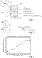
- FIG. 1 shows a radar system 150 with a radar device 100 (e.g. an UWB radar chip) and a target 140, according to an exemplary embodiment of the disclosure.
- the radar device 100 comprises a transmitter 110 with a transmitter antenna 111, configured to transmit an RF signal, here an UWB pulse.
- the radar device 100 further comprises a first receiver 120, configured to receive a first reflection (at the target 140) of the RF signal.
- the transmitter 110 and the first receiver 120 are associated with each other and share a common antenna 111 (e.g. a common RF pin).
- the transmitter 110 is hence spatially closer to the first receiver 120 than to a second receiver 130 (here on-chip co-allocated), configured to receive a second reflection of the RF signal, which is different (in phase) from the first reflection.
- the transmitter 110 and the receivers 120, 130 are coupled with a control device (not shown) which determines a PDoA from the different phases of the first reflection and the second reflection.
- the Figure also shows the delay ⁇ 0 through the transmitter 110 (which also depends on the process) as well as the delay ⁇ SI due to the SI path.
- ⁇ SI the delay on the transmitter 110, the first receiver 120, and the second receiver 130 are completely cancelled.
- the additional delay ⁇ SI (or phase ⁇ SI ) can be determined and compensated as part of the antenna measurement.
- This SI delay is hereby a fixed value that does not depend on device (chip)-conditions (e.g. process spread).
- Figure 3 illustrates a comparison of measured (y-axis) and true (x-axis) angles of arrival, according to an exemplary embodiment of the disclosure. It can be seen that very accurate angle determination is possible. Further, a monolithic curve can be observed as would be the case of a calibrated system. It follows that the described (calibration-free compensated approach) may yield comparable or better results than conventional approaches, yet without cost-consuming calibration processes.
Landscapes
- Engineering & Computer Science (AREA)
- Radar, Positioning & Navigation (AREA)
- Remote Sensing (AREA)
- Computer Networks & Wireless Communication (AREA)
- Physics & Mathematics (AREA)
- General Physics & Mathematics (AREA)
- Radar Systems Or Details Thereof (AREA)
Applications Claiming Priority (1)
| Application Number | Priority Date | Filing Date | Title |
|---|---|---|---|
| IN202341065580 | 2023-09-29 |
Publications (1)
| Publication Number | Publication Date |
|---|---|
| EP4530663A1 true EP4530663A1 (de) | 2025-04-02 |
Family
ID=89663392
Family Applications (1)
| Application Number | Title | Priority Date | Filing Date |
|---|---|---|---|
| EP24153204.3A Pending EP4530663A1 (de) | 2023-09-29 | 2024-01-22 | Radarvorrichtung mit selbstinterferenzbasierter kompensation |
Country Status (3)
| Country | Link |
|---|---|
| US (1) | US20260086192A1 (de) |
| EP (1) | EP4530663A1 (de) |
| CN (1) | CN119738806A (de) |
Families Citing this family (1)
| Publication number | Priority date | Publication date | Assignee | Title |
|---|---|---|---|---|
| CN120436614A (zh) * | 2025-04-27 | 2025-08-08 | 西安理工大学 | 基于时间调制阵列的多用户呼吸监测方法及系统 |
Citations (2)
| Publication number | Priority date | Publication date | Assignee | Title |
|---|---|---|---|---|
| US20130113653A1 (en) * | 2010-07-16 | 2013-05-09 | Panasonic Corporation | Radar device |
| KR101807522B1 (ko) * | 2016-06-29 | 2017-12-12 | 재단법인대구경북과학기술원 | 자기 간섭을 이용한 레이더의 수신 채널 보상 장치 및 그 방법 |
-
2024
- 2024-01-22 EP EP24153204.3A patent/EP4530663A1/de active Pending
- 2024-08-21 CN CN202411151494.3A patent/CN119738806A/zh active Pending
- 2024-09-17 US US18/887,456 patent/US20260086192A1/en active Pending
Patent Citations (2)
| Publication number | Priority date | Publication date | Assignee | Title |
|---|---|---|---|---|
| US20130113653A1 (en) * | 2010-07-16 | 2013-05-09 | Panasonic Corporation | Radar device |
| KR101807522B1 (ko) * | 2016-06-29 | 2017-12-12 | 재단법인대구경북과학기술원 | 자기 간섭을 이용한 레이더의 수신 채널 보상 장치 및 그 방법 |
Also Published As
| Publication number | Publication date |
|---|---|
| US20260086192A1 (en) | 2026-03-26 |
| CN119738806A (zh) | 2025-04-01 |
Similar Documents
| Publication | Publication Date | Title |
|---|---|---|
| JP7667331B2 (ja) | 周囲をキャプチャする方法および装置 | |
| EP3640675B1 (de) | Schätzung des winkels eines menschlichen zieles unter verwendung von millimeterwellenradar | |
| US11057862B2 (en) | Wi-Fi radar detection using synchronized wireless access point | |
| US9618616B2 (en) | Radar apparatus | |
| US9772402B2 (en) | Multiplatform GMTI radar with adaptive clutter suppression | |
| US9470784B2 (en) | Radar device | |
| EP4071501B1 (de) | Signalverarbeitungsverfahren und -vorrichtung | |
| US7821443B2 (en) | Dual mode radar methods and systems | |
| JP5197138B2 (ja) | マルチスタティックレーダ装置 | |
| CN108603928A (zh) | 用于降低由雷达系统中的相位噪声引起的干扰的方法和系统 | |
| US12222436B2 (en) | Radar method and radar system | |
| US11422220B2 (en) | Method and apparatus for determining the angle of departure | |
| US20250035767A1 (en) | Positioning system and vehicle including positioning system, and positioning method | |
| Herschfelt et al. | Joint positioning-communications system design: Leveraging phase-accurate time-of-flight estimation and distributed coherence | |
| US20260086192A1 (en) | Radar device with self-interference based compensation | |
| CN119556272A (zh) | 确定雷达系统的目标信息的方法以及雷达系统和交通工具 | |
| CN115734155A (zh) | 控制装置、系统以及控制方法 | |
| JP6324108B2 (ja) | 合成開口レーダ装置 | |
| US20260098935A1 (en) | Radar device with enlarged bandwidth | |
| CN112204422B (zh) | 速度测量方法、多输入多输出雷达和可移动平台 | |
| EP4589332A1 (de) | Hf-vorrichtung mit selbstkalibrierung einer kommunikationsfehlanpassung | |
| Mercuri et al. | A practical distance measurement improvement technique for a SFCW-based health monitoring radar | |
| EP4538736A1 (de) | Vorrichtung mit lenkung und kanalzusammenfügung für eine erweiterte bandbreite | |
| US20250172658A1 (en) | Radar system with spatial filtering functionality, motor vehicle and method for operating the radar system | |
| US20250231273A1 (en) | Radar method and radar system |
Legal Events
| Date | Code | Title | Description |
|---|---|---|---|
| PUAI | Public reference made under article 153(3) epc to a published international application that has entered the european phase |
Free format text: ORIGINAL CODE: 0009012 |
|
| STAA | Information on the status of an ep patent application or granted ep patent |
Free format text: STATUS: THE APPLICATION HAS BEEN PUBLISHED |
|
| AK | Designated contracting states |
Kind code of ref document: A1 Designated state(s): AL AT BE BG CH CY CZ DE DK EE ES FI FR GB GR HR HU IE IS IT LI LT LU LV MC ME MK MT NL NO PL PT RO RS SE SI SK SM TR |
|
| STAA | Information on the status of an ep patent application or granted ep patent |
Free format text: STATUS: REQUEST FOR EXAMINATION WAS MADE |
|
| 17P | Request for examination filed |
Effective date: 20251002 |