EP4530641A1 - Filtre passe-bas adaptatif pour détection de passage par zéro - Google Patents
Filtre passe-bas adaptatif pour détection de passage par zéro Download PDFInfo
- Publication number
- EP4530641A1 EP4530641A1 EP24197817.0A EP24197817A EP4530641A1 EP 4530641 A1 EP4530641 A1 EP 4530641A1 EP 24197817 A EP24197817 A EP 24197817A EP 4530641 A1 EP4530641 A1 EP 4530641A1
- Authority
- EP
- European Patent Office
- Prior art keywords
- phase
- signal
- offset
- input signal
- yout
- Prior art date
- Legal status (The legal status is an assumption and is not a legal conclusion. Google has not performed a legal analysis and makes no representation as to the accuracy of the status listed.)
- Pending
Links
Images


Classifications
-
- G—PHYSICS
- G01—MEASURING; TESTING
- G01R—MEASURING ELECTRIC VARIABLES; MEASURING MAGNETIC VARIABLES
- G01R19/00—Arrangements for measuring currents or voltages or for indicating presence or sign thereof
- G01R19/175—Indicating the instants of passage of current or voltage through a given value, e.g. passage through zero
-
- H—ELECTRICITY
- H03—ELECTRONIC CIRCUITRY
- H03K—PULSE TECHNIQUE
- H03K5/00—Manipulating of pulses not covered by one of the other main groups of this subclass
- H03K5/153—Arrangements in which a pulse is delivered at the instant when a predetermined characteristic of an input signal is present or at a fixed time interval after this instant
- H03K5/1536—Zero-crossing detectors
-
- G—PHYSICS
- G01—MEASURING; TESTING
- G01R—MEASURING ELECTRIC VARIABLES; MEASURING MAGNETIC VARIABLES
- G01R25/00—Arrangements for measuring phase angle between a voltage and a current or between voltages or currents
- G01R25/04—Arrangements for measuring phase angle between a voltage and a current or between voltages or currents involving adjustment of a phase shifter to produce a predetermined phase difference, e.g. zero difference
-
- H—ELECTRICITY
- H03—ELECTRONIC CIRCUITRY
- H03H—IMPEDANCE NETWORKS, e.g. RESONANT CIRCUITS; RESONATORS
- H03H11/00—Networks using active elements
- H03H11/02—Multiple-port networks
- H03H11/04—Frequency selective two-port networks
-
- H—ELECTRICITY
- H03—ELECTRONIC CIRCUITRY
- H03K—PULSE TECHNIQUE
- H03K5/00—Manipulating of pulses not covered by one of the other main groups of this subclass
- H03K5/156—Arrangements in which a continuous pulse train is transformed into a train having a desired pattern
- H03K5/1565—Arrangements in which a continuous pulse train is transformed into a train having a desired pattern the output pulses having a constant duty cycle
Definitions
- This disclosure is related to power quality (PQ) measurement systems and, more specifically, to a method and system for detecting the zero crossing (ZC) events of voltage and current signals with high degree of precision and reduced consumption of computational resources.
- PQ power quality
- ZC zero crossing
- ZC zero crossing
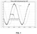
- LPF low-pass filter
- phase shift is particularly concerning given that the primary frequency of power grid systems can fluctuate within specific ranges and may shift over time.
- Such phase shifts while sometimes compensable with hardware and software procedures, typically cannot be corrected in real-time, leading to inaccuracies in the measurements.
- a LPF may not be able to completely remove the harmonic components present in the input, so there could be a change in the shape of the output waveform and consequently a moving of the zero crossing and a change of the duty cycle.
- the circuit includes a low-pass filter (LPF) configured to receive an input signal indicative of the power signal and to introduce a phase shift dependent on the frequency of the input signal, and filter circuitry.
- the filter circuitry is configured to receive the output of the LPF and to apply a fixed phase shift thereto, and adjust phase, and optionally DC offset, of the output of the LPF based on control signals to produce a filtered output signal.
- LPF low-pass filter
- Control circuitry includes a zero crossing detector configured to receive the input signal and the filtered output signal, detect zero crossings of the input signal and the filtered output signal, assert a digital zero cross signal at each zero crossing, and determine a phase shift, and optionally a DC offset, between the input signal and filtered output signal.
- the control circuitry further includes a controller configured to generate the control signals, based upon the phase shift and optionally upon the DC offset, such that a total phase shift between the input signal and the filtered output signal is constant and there is a same duty cycle between the input signal and the filtered output signal, thereby providing for accurate zero crossing detection by the zero crossing detector.
- the control circuitry may also include a slope detector configured to, at each zero crossing of the input signal and the filtered output signal, determine the difference between slopes of the input signal and the filtered output signal and provide feedback to the controller to cause the controller to adjust phase correction, and optionally DC offset correction, applied by the filter circuitry to the input signal based on the determined difference.
- a slope detector configured to, at each zero crossing of the input signal and the filtered output signal, determine the difference between slopes of the input signal and the filtered output signal and provide feedback to the controller to cause the controller to adjust phase correction, and optionally DC offset correction, applied by the filter circuitry to the input signal based on the determined difference.
- the controller may be configured to transition between multiple states to adjust the phase correction, and optionally the DC offset correction, applied by the filter circuitry, the multiple states including at least: a locked state, in which no adjustments are made to the phase correction; a phase fine state in which fine adjustments are made to the phase correction; a phase gross state in which gross adjustments are made to the phase correction; optionally an offset fine state in which fine adjustments are made to the DC offset correction; and optionally an offset gross state in which gross adjustments are made to the DC offset correction.
- the controller may be configured to utilize gross and fine lookup tables to determine adjustments for the phase correction applied by the filter circuitry to the input signal.
- the gross lookup table may contain coefficients that increment the phase correction applied by the filter circuitry by different given gross degree values
- the fine lookup table may contain coefficients that increment the phase correction applied by the filter circuitry for given different fine degree values.
- the gross and fine lookup tables may contain coefficients derived from historical zero crossing data of the input signal and output filtered signal.
- the control circuitry may be configured to generate phase adjustment control signals, and optionally offset adjustment control signals, and the filter circuitry may be configured to use these phase adjustment control signals, and optionally these offset adjustment control signals, to adjust the phase correction, and optionally the offset correction, applied by the filter circuitry to the input signal.
- the total phase shift between the input signal and the filtered output signal may be 180°.
- the filter circuitry may include a fixed all-pass (FAP) filter configured to receive the output of the LPF and to apply the fixed phase shift thereto, and an adaptive all-pass (AAP) filter configured to receive the output of the FAP filter and adjust its phase, and optionally its DC offset, based on the control signals to produce the filtered output signal.
- FAP fixed all-pass
- AAP adaptive all-pass
- the method includes receiving an input signal indicative of the power signal at a low-pass filter (LPF) which introduces a phase shift dependent on a frequency of the input signal, passing the output of the LPF through filter circuitry which applies a fixed phase shift thereto and which adjusts phase of the output of the LPF based upon received control signals to produce a filtered output signal, detecting zero crossings of the input signal and the filtered output signal and asserting a digital zero cross signal at each zero crossing, and determining a phase shift and DC offset between the input signal and filtered output signal.
- LPF low-pass filter
- the method further includes generating the control signals based upon the determined phase shift and DC offset such that a total phase shift between the input signal and the filtered output signal remains constant and there is a same duty cycle between the input signal and the filtered output signal to thereby provide for accurate detection of the zero crossings of the input signal.
- the method may include determining a difference between slopes of the input signal and the filtered output signal.
- the method may include providing feedback based on the determined difference to adjust phase and DC offset correction applied by the AAP filter to the input signal.
- the method may further include transitioning between multiple states to adjust the phase and DC offset correction applied to the input signal by the AAP filter, the states including at least: a locked state, in which no adjustments are made to the phase correction; a phase fine state in which fine adjustments are made to the phase correction; a phase gross state in which gross adjustments are made to the phase correction; an offset fine state in which fine adjustments are made to the DC offset correction; and an offset gross state in which gross adjustments are made to the DC offset correction.
- phase fine state and the phase gross state gross and fine lookup tables may be utilized to determine adjustments for the phase correction applied by the AAP filter to the input signal.
- Passing the output of the LPF through filter circuitry which applies a fixed phase shift thereto and which adjusts phase and DC offset of the output of the LPF based upon received control signals to produce a filtered output signal may include passing the output of the LPF through a fixed all-pass (FAP) filter which applies a fixed phase shift thereto, and passing the output of the FAP filter through an adaptive all-pass (AAP) filter which adjusts phase and DC offset of the output of the FAP filter based on received control signals to produce a filtered output signal.
- FAP fixed all-pass
- AAP adaptive all-pass
- the following disclosure enables a person skilled in the art to make and use the subject matter described herein.
- the general principles outlined in this disclosure can be applied to embodiments and applications other than those detailed above without departing from the spirit and scope of this disclosure. It is not intended to limit this disclosure to the embodiments shown, but to accord it the widest scope consistent with the principles and features disclosed or suggested herein.
- the "offset" of a signal may refer to DC offset of that signal.
- FIG. 2 describes a circuit 10 configured to detect zero crossings (ZC) in power grid signals.
- Circuit 10 incorporates both a fixed all-pass (FAP) filter and an adaptive all-pass (AAP) filter in its signal processing chain. These components work together to dynamically adjust for phase shifts, harmonics, and other signal distortions so that there is a set constant phase shift between the input signal to the signal processing chain and the output signal from the signal processing chain and so that offset correction is performed to align the zero crossings of the input and output signals. When these conditions are met, ZC detection performed by the circuit 10 is accurate.
- FAP fixed all-pass
- AAP adaptive all-pass
- circuit 10 comprises a low-pass filter (LPF) 11 that receives an input signal (IN) indicative of a power signal.
- LPF 11 filters the signal, introducing a phase shift that is at least partially dependent on the input frequency.
- FAP fixed all-pass
- the signal passes through the fixed all-pass (FAP) filter 12, which applies a consistent phase shift.
- FAP 12 passes through the fixed all-pass (FAP) filter 12, which applies a consistent phase shift.
- the output from FAP 12 is routed to the adaptive all-pass (AAP) filter 13.
- the AAP 13 adjusts the phase and DC offset of the input signal based on control signals ADJ_phase and ADJ offset received from control circuitry 14; stated differently, the control signals ADJ_phase and ADJ_offset adjust the transfer function of the AAP 13.
- AAP 13 yields a filtered output signal YOUT.
- the goal is for the phase shift from the input signal IN to the filtered output signal YOUT to be a given desired value (e.g., 180°), with the set phase shift applied by the FAP 12 being a set fixed value (e.g., 80°) and the phase shift applied by the AAP 13 being a dynamically adjustable value (e.g., between 0° and 90°) to dynamically adapt to a phase shift applied by the LPF 11 (for example, 45° to 55°) that is dependent upon the frequency of the input signal IN.
- a given desired value e.g. 180°
- the set phase shift applied by the FAP 12 being a set fixed value (e.g., 80°)
- the phase shift applied by the AAP 13 being a dynamically adjustable value (e.g., between 0° and 90°) to dynamically adapt to a phase shift applied by the LPF 11 (for example, 45° to 55°) that is dependent upon the frequency of the input signal IN.
- the goal is for a corrective offset to be applied to the output of the FAP 13 by the AAP 13 so that the displacement of the zero crossing in YOUT due to the shifting of harmonics by the LPF 11 is compensated by the adding of a proper offset.
- control circuitry 14 analyzes both the original input signal (IN) and the filter output signal (YOUT) to generate the phase and offset adjustment control signals ADJ_phase and ADJ_offset. Included with the operations of the control circuitry 14 is the detection of zero crosses, in response to which the control circuitry 14 asserts a digital zero cross signal (DZC) when zero crossing of the input signal IN is identified.
- DZC digital zero cross signal
- This digital zero cross signal DZC may be used in the determination of power quality (PQ), for example, and is particularly accurate once convergence has been successful.
- Convergence refers to the process by which the zero-crossing detection circuit 10 self-adjusts and stabilizes to consistently and accurately detect zero-crossings of the input signal IN over consecutive cycles.
- the control circuitry 14 includes a zero crossing detector 20 that receives the input signal IN and the filtered output signal YOUT. In addition to generating the digital zero cross signal DZC, the zero crossing detector 20 evaluates the values of signals IN and YOUT at the zero crosses in order to determine the direction DIR (e.g., related to the phase shift between IN and YOUT) and offset OFFSET (related to distortion in IN, which as will be explained, will be used in calculating ADJ_offset).
- DIR e.g., related to the phase shift between IN and YOUT
- offset OFFSET related to distortion in IN, which as will be explained, will be used in calculating ADJ_offset
- Operations within the zero crossing detector 20 include, during each cycle, computing the combined value zc as (IN+YOUT)/2 every time either signal IN or signal YOUT crosses zero with positive slope. From this, two signals, INC and DEC, are derived. Specifically, when YOUT crosses zero, INC is set to 1 if (IN+YOUT)/2 exceeds a constant RESOL_THRES, otherwise it remains 0. Similarly, when IN crosses zero, DEC is set to 1 if (IN+YOUT)/2 exceeds a constant RESOL THRES, otherwise it remains 0.
- the DIR and OFFSET signals, output by the zero crossing detector 20, are decoded based on the following table: INC DEC DIR OFFSET 0 0 0 1 0 1 -1 0 1 0 1 0 1 1 0 -1
- the RESOL_THRES constant is updated at each cycle by the zero crossing detector 20. This update depends on the peak value of the input IN and the estimated distortion in IN, as well as a calculated slope.
- the determined direction DIR is integrated by a phase buffer 22 to produce a distance metric DIST that is proportional to the phase mismatch between IN and YOUT.
- the determined offset OFFSET is integrated by an offset buffer 23 to produce a distortion metric DISTORT that is proportional to the harmonics in signal IN.
- a finite state machine (FSM) 24 receives the distance metric DIST and the distortion metric DISTORT, and generates a gross/fine control signal GFCTRL and an offset control signal OFCTRL.
- the gross/fine control signal GFCTRL is used to perform lookups in respective gross/fine coefficient lookup tables 25 to generate the phase adjustment control signal ADJ_phase
- the offset control signal OFCTRL is provided to an adder 26 that incrementally changes and adds a constant to the offset adjustment control signal ADJ_offset, used by the AAP 13 in applying an offset to the output of the FAP 12 to achieve a condition of minimum for the metric DISTORT.
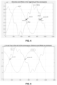
- FIGS. 4-5 The effect of the operation of the circuit 10 on the input signal IN to produce the filtered output signal YOUT may be seen in the series of FIGS. 4-5 .
- FIG. 4 shown in FIG. 4 are signal IN and signal YOUT, with the phase shift (labeled as direction) and offset therebetween being indicated, and shown in FIG. 5 are signal IN and signal YOUT.
- FIG. 5 shows signal IN and signal YOUT.
- the phase shift is set to a desired value of substantially 180°, and no DC offset between IN and YOUT is present.
- the evolution of the distance metric DIST and distortion metric DISTORT over time through the operation of the FSM 24 generating new values of the phase adjustment control signal ADJ_phase and offset adjustment control signal ADJ_offset in response to new values of signals IN and YOUT may be seen in FIG. 6 , where it is shown how these metrics converge about zero between 500 and 1000 cycles of the input signal IN.
- This calculated SLOPE value influences the update of RESOL_THRES by the zero crossing detector 20, enhancing detection accuracy in the presence of harmonics.
- the FSM 24 generates ADJ_phase and ADJ offset based upon DIST (an integer proportional to the phase mismatch between IN and YOUT) and DISTORT (an integer proportional to the harmonics in signal IN) so that there is a set constant phase (180 degrees) shift between IN and YOUT and such that IN and YOUT have the same duty cycle (e.g. the two ZC are identical). In this condition, as explained, zero crossing detection is accurate.
- the state transitions of the FSM 24 to achieve this operation will now be described with reference to FIG. 7 .
- the states transition between the following: ST0 (Locked State): Here the zero crossing aligns with minimal error, and the coefficients remain constant.
- Phase Fine State In this state, phase refinement takes place through the updating of the phase adjustment control signal ADJ_phase using the fine lookup table. Transitions occur when:
- the gross and fine lookup tables used by the FSM 24 in generating and dynamically modifying ADJ_phase, are now described in greater detail.
- the gross lookup table contains 80 coefficients, each spanning a width of 20 bits. Each of these coefficients increments the filter phase by approximately 1.125 degrees.
- the coefficient index is set at 40, which configures the AAP phase to -45 degrees.
- the coefficient k for ADJ_phase the current cycle is determined by summing the current index with DIR, which can either increment, decrement, or maintain its value.
- the fine lookup table contains 80 constants, each with an 8-bit width.
- the offset coefficient k for ADJ_offset for the current cycle is calculated by the FSM 24 by adding a given number (e.g., 300, this number being about 1/30000 of the full scale digital swing 2 23 ) to the coefficient of the previous cycle, k-1.
- the offset coefficient for the current cycle k is calculated by the FSM 24 by adding a given number (e.g., 4000, this number being about 1/2000 of the full scale digital swing 2 23 ) to the coefficient of the previous cycle, k-1.
- convergence refers to the process by which the zero-crossing detection circuit 10 self-adjusts and stabilizes through adjustment of ADJ_phase and ADJ_offset to consistently and accurately detect zero-crossings of the input signal over consecutive cycles.
- a quicker convergence time signifies that the circuit 10 reaches stable operating condition in fewer signal cycles, thereby offering rapid and reliable zero-crossing detection.
- zero-crossing error quantifies the difference or discrepancy between the exact point where the input signal crosses zero and the point where the zero-crossing detection circuit 10 identifies or detects the zero-crossing. A smaller zero-crossing error indicates a higher precision in detection.
- FIG. 9 the performance of the zero-crossing detection circuit 10 when subjected to a pure sinusoid input is shown. As illustrated in FIG. 9 , robust performance is exhibited with a convergence time averaging approximately 150 cycles. This convergence time remains consistent across varying input frequencies ranging between 45 to 65 Hz. The precision of the zero-crossing detection circuit 10 is further highlighted with a phase error being maintained under 0.01 degrees and a zero-crossing error s featuring the circuit's accuracy in pinpointing the exact zero-crossing point. Additionally, frequency error observed is less than 0.2 mHz.
- One of the attributes of the circuit 10, as can be deduced from FIG. 9 is its ability to accurately track changes in the input frequency at a rate of 0.02 Hz/sec.
- FIG. 10 the graph illustrates phase error as a function of the Signal to Noise Ratio (SNR), while FIG. 11 provides insights into zero-crossing error relative to SNR.
- the input signal is a pure sinusoid subjected to white noise interference.
- the robustness of the circuit 10 is evident as phase errors are kept below 0.1 degrees. Even with noise interference, zero-crossing errors remain below 10 microseconds for SNRs greater than 30 dB, emphasizing the precision in detection provided by the circuit 10.
- the frequency error in these conditions is observed to be less than 0.3 mHz.
- a typical lock time of under 500 sinusoid cycles is achieved, reinforcing the reliability of the circuit 10.
- FIGS. 12 and 13 the performance of the zero-crossing detection circuit is illustrated in the presence of both the 2nd and the 3rd harmonics on a pure sinusoid input.
- the circuit 10 demonstrates a lock time under 1500 sinusoid cycles, s featuring its adaptability and resilience to harmonic interferences.
- FIGS. 14 and 15 present a view of the performance of the circuit 10 when subjected to both distortion and noise. These figures elaborate on the phase error in the presence of both noise and harmonics, further underlining the capability of the circuit 10 to consistently detect zero-crossings even in challenging signal conditions.
- the zero-crossing detection circuit 10 provides high precision, reliability, and adaptability across various signal conditions, making it usable in a wide variety of applications.
- a switch/dimmer circuit 32 receives a power signal from power mains and provides it (optionally with dimming control) to a light 31.
- the switch/dimmer circuit 32 is driven by output from a driver 33, with the driver 33 being controlled by output from a microcontroller 34.
- the microcontroller 34 controls the driver 33 based upon feedback about the power signal provided by a power meter circuit 35.
- the power meter circuit 35 is described in greater detail with reference to FIG. 17 .
- a first ADC 41a generates a digital representation of the voltage of the power signal
- a decimator 42a decimates that digital representation
- a highpass filter 43a performs high pass filtering (and optionally applies gain to) the decimates version of the digital representation.
- a calibration circuit 44a calibrates the resulting filtered signal to provide a digital voltage signal DV
- an adaptive low-pass filter 10a (including the zero-crossing detection circuit 10 described above) determines zero crossings of the filtered signal after calibration and asserts a signal DVZC based thereupon.
- a second ADC 41b generates a digital representation of the current of the power signal
- a decimator 42b decimates that digital representation
- a highpass filter 43b performs high pass filtering (and optionally applies gain to) the decimated version of the digital representation.
- a calibration circuit 44b calibrates the resulting filtered signal to provide a digital current signal DI
- an adaptive low-pass filter 10b (including the zero-crossing detection circuit 10 described above) determines zero crossings of the filtered signal after calibration and asserts a signal DIZC based thereupon.
- DV, DVZC, DI, and DIZC are utilized by the MCU 34 in controlling the driver 33.
Landscapes
- Physics & Mathematics (AREA)
- Nonlinear Science (AREA)
- General Physics & Mathematics (AREA)
- Manipulation Of Pulses (AREA)
Applications Claiming Priority (1)
| Application Number | Priority Date | Filing Date | Title |
|---|---|---|---|
| US18/371,038 US12294375B2 (en) | 2023-09-21 | 2023-09-21 | Adaptive low-pass filter for zero-crossing detection |
Publications (1)
| Publication Number | Publication Date |
|---|---|
| EP4530641A1 true EP4530641A1 (fr) | 2025-04-02 |
Family
ID=92633930
Family Applications (1)
| Application Number | Title | Priority Date | Filing Date |
|---|---|---|---|
| EP24197817.0A Pending EP4530641A1 (fr) | 2023-09-21 | 2024-09-02 | Filtre passe-bas adaptatif pour détection de passage par zéro |
Country Status (3)
| Country | Link |
|---|---|
| US (1) | US12294375B2 (fr) |
| EP (1) | EP4530641A1 (fr) |
| CN (1) | CN119675631A (fr) |
Citations (5)
| Publication number | Priority date | Publication date | Assignee | Title |
|---|---|---|---|---|
| DE19535271A1 (de) * | 1995-09-22 | 1997-03-27 | Werner Hanke | Nulldurchgangserkennung mit phasenkorrigiertem Filter |
| JP2005166037A (ja) * | 2003-11-13 | 2005-06-23 | Fuji Electric Systems Co Ltd | 電力変換装置および交流波形の調整方法 |
| US20110291735A1 (en) * | 2010-06-01 | 2011-12-01 | Novar Ed&S Limited | Switch circuit |
| CN107643442A (zh) * | 2016-07-22 | 2018-01-30 | 刘铮 | 一种新型的高精度过零检测方法 |
| CN112540219A (zh) * | 2020-11-13 | 2021-03-23 | 珠海格力电器股份有限公司 | 过零检测电路及控制电路 |
Family Cites Families (7)
| Publication number | Priority date | Publication date | Assignee | Title |
|---|---|---|---|---|
| US7126378B2 (en) * | 2003-12-17 | 2006-10-24 | Rambus, Inc. | High speed signaling system with adaptive transmit pre-emphasis |
| US7890562B2 (en) | 2006-09-29 | 2011-02-15 | Teradyne, Inc. | Sine wave generator with dual port look-up table |
| CA2827212A1 (fr) | 2011-02-18 | 2012-08-23 | Arteche Lantegi Elkartea, S.A. | Systeme et procede de surveillance de la forme d'onde de la tension du reseau electrique |
| US9634624B2 (en) | 2014-12-24 | 2017-04-25 | Stmicroelectronics S.R.L. | Method of operating digital-to-analog processing chains, corresponding device, apparatus and computer program product |
| US9692331B2 (en) | 2015-02-27 | 2017-06-27 | Microchip Technologies Incorporated | BLDC adaptive zero crossing detection |
| US11251766B2 (en) | 2020-01-13 | 2022-02-15 | Maxim Integrated Products, Inc. | Ultra-wide band frequency offset estimation systems and methods for analog coherent receivers |
| DE102020116281A1 (de) | 2020-06-19 | 2021-12-23 | Endress+Hauser SE+Co. KG | Vibronischer Sensor |
-
2023
- 2023-09-21 US US18/371,038 patent/US12294375B2/en active Active
-
2024
- 2024-09-02 EP EP24197817.0A patent/EP4530641A1/fr active Pending
- 2024-09-13 CN CN202411283278.4A patent/CN119675631A/zh active Pending
Patent Citations (5)
| Publication number | Priority date | Publication date | Assignee | Title |
|---|---|---|---|---|
| DE19535271A1 (de) * | 1995-09-22 | 1997-03-27 | Werner Hanke | Nulldurchgangserkennung mit phasenkorrigiertem Filter |
| JP2005166037A (ja) * | 2003-11-13 | 2005-06-23 | Fuji Electric Systems Co Ltd | 電力変換装置および交流波形の調整方法 |
| US20110291735A1 (en) * | 2010-06-01 | 2011-12-01 | Novar Ed&S Limited | Switch circuit |
| CN107643442A (zh) * | 2016-07-22 | 2018-01-30 | 刘铮 | 一种新型的高精度过零检测方法 |
| CN112540219A (zh) * | 2020-11-13 | 2021-03-23 | 珠海格力电器股份有限公司 | 过零检测电路及控制电路 |
Non-Patent Citations (1)
| Title |
|---|
| VAINIO O ET AL: "Adaptive lowpass filters for zero-crossing detectors", IECON-2002. PROCEEDINGS OF THE 28TH. ANNUAL CONFERENCE OF THE IEEE INDUSTRIAL ELECTRONICS SOCIETY. SEVILLA, SPAIN, NOV. 5 - 8, 2002; [ANNUAL CONFERENCE OF THE IEEE INDUSTRIAL ELECTRONICS SOCIETY], IEEE, NEW YORK,NY, US, vol. 2, 5 November 2002 (2002-11-05), pages 1483 - 1486, XP010632925, ISBN: 978-0-7803-7474-4, DOI: 10.1109/IECON.2002.1185498 * |
Also Published As
| Publication number | Publication date |
|---|---|
| US12294375B2 (en) | 2025-05-06 |
| CN119675631A (zh) | 2025-03-21 |
| US20250105831A1 (en) | 2025-03-27 |
Similar Documents
| Publication | Publication Date | Title |
|---|---|---|
| US7932844B1 (en) | Circuits and methods for calibrating a frequency response of a filter | |
| EP0473373A2 (fr) | Système de calibrage pour récepteur à conversion directe | |
| EP1324503A2 (fr) | Récepteur à conversion directe, equipement radio mobile utilisant ledit, et procedé de réception d'un signal radiofréquence | |
| KR20040033287A (ko) | 신호 시간 정렬 | |
| WO2021067932A1 (fr) | Correction de non-linéarité | |
| CN120165682B (zh) | 一种基于频率自适应技术的数字锁相放大器与微弱信号采集系统及方法 | |
| EP1819040B1 (fr) | Dispositif pour la compensation des distorsions non-linéaires et méthode | |
| EP1819039A1 (fr) | Dispositif et méthode pour compenser la distorsion | |
| EP4530641A1 (fr) | Filtre passe-bas adaptatif pour détection de passage par zéro | |
| JP5935631B2 (ja) | 補償装置及び無線通信装置 | |
| WO2010047005A1 (fr) | Circuit numérique à boucle d’asservissemnt de phase et appareil de communication | |
| EP2374213B1 (fr) | Procédé et appareil d'élimination d'erreur du décalage en courant continu dans un récepteur à conversion directe | |
| US8374287B2 (en) | FM detector, signal interpolation method, and related program | |
| JP3518430B2 (ja) | デジタルfm復調器 | |
| US7054395B2 (en) | Automatic gain control for digital demodulation apparatus | |
| JP3751251B2 (ja) | 映像信号処理装置及び方法 | |
| CN112953572B (zh) | 一种低延迟小抖动电台静噪方法 | |
| JPWO2011001577A1 (ja) | ポーラ変調回路を備える送信機 | |
| US20200153675A1 (en) | Iq mismatch correction filter | |
| JP2004514330A (ja) | 非対称過渡信号の検出及び補正 | |
| JP7581305B2 (ja) | クロックリカバリ回路、誤り率測定装置、及び誤り率測定方法 | |
| Shin | An improved oscillator based adaptive notch filter algorithm for noisy sinusoids | |
| US20090256595A1 (en) | Phase Detecting Module and Detecting Method Thereof | |
| KR100285434B1 (ko) | 브이.에스.비 방식 수신기의 적응 위상추적장치 및 방법 | |
| JP2000312155A (ja) | Fm受信装置 |
Legal Events
| Date | Code | Title | Description |
|---|---|---|---|
| PUAI | Public reference made under article 153(3) epc to a published international application that has entered the european phase |
Free format text: ORIGINAL CODE: 0009012 |
|
| STAA | Information on the status of an ep patent application or granted ep patent |
Free format text: STATUS: THE APPLICATION HAS BEEN PUBLISHED |
|
| AK | Designated contracting states |
Kind code of ref document: A1 Designated state(s): AL AT BE BG CH CY CZ DE DK EE ES FI FR GB GR HR HU IE IS IT LI LT LU LV MC ME MK MT NL NO PL PT RO RS SE SI SK SM TR |
|
| STAA | Information on the status of an ep patent application or granted ep patent |
Free format text: STATUS: REQUEST FOR EXAMINATION WAS MADE |
|
| 17P | Request for examination filed |
Effective date: 20250910 |