EP4530557A1 - Cryocooler - Google Patents
Cryocooler Download PDFInfo
- Publication number
- EP4530557A1 EP4530557A1 EP24198615.7A EP24198615A EP4530557A1 EP 4530557 A1 EP4530557 A1 EP 4530557A1 EP 24198615 A EP24198615 A EP 24198615A EP 4530557 A1 EP4530557 A1 EP 4530557A1
- Authority
- EP
- European Patent Office
- Prior art keywords
- displacer
- regenerator material
- cryocooler
- magnetic regenerator
- based magnetic
- Prior art date
- Legal status (The legal status is an assumption and is not a legal conclusion. Google has not performed a legal analysis and makes no representation as to the accuracy of the status listed.)
- Pending
Links
- 239000000463 material Substances 0.000 claims abstract description 139
- 239000000919 ceramic Substances 0.000 claims abstract description 61
- 238000001816 cooling Methods 0.000 claims abstract description 60
- 229910052751 metal Inorganic materials 0.000 claims description 30
- 239000002184 metal Substances 0.000 claims description 30
- 239000007789 gas Substances 0.000 description 32
- RYGMFSIKBFXOCR-UHFFFAOYSA-N Copper Chemical compound [Cu] RYGMFSIKBFXOCR-UHFFFAOYSA-N 0.000 description 9
- 229910052802 copper Inorganic materials 0.000 description 9
- 239000010949 copper Substances 0.000 description 9
- 239000008187 granular material Substances 0.000 description 9
- 239000001307 helium Substances 0.000 description 5
- 229910052734 helium Inorganic materials 0.000 description 5
- SWQJXJOGLNCZEY-UHFFFAOYSA-N helium atom Chemical compound [He] SWQJXJOGLNCZEY-UHFFFAOYSA-N 0.000 description 5
- 238000006243 chemical reaction Methods 0.000 description 4
- 230000000052 comparative effect Effects 0.000 description 4
- 239000002245 particle Substances 0.000 description 4
- HCHKCACWOHOZIP-UHFFFAOYSA-N Zinc Chemical compound [Zn] HCHKCACWOHOZIP-UHFFFAOYSA-N 0.000 description 3
- 239000000654 additive Substances 0.000 description 3
- 230000000996 additive effect Effects 0.000 description 3
- 230000000694 effects Effects 0.000 description 3
- 230000020169 heat generation Effects 0.000 description 3
- 239000007788 liquid Substances 0.000 description 3
- 239000007769 metal material Substances 0.000 description 3
- 230000004048 modification Effects 0.000 description 3
- 238000012986 modification Methods 0.000 description 3
- 230000000737 periodic effect Effects 0.000 description 3
- 239000010935 stainless steel Substances 0.000 description 3
- 229910001220 stainless steel Inorganic materials 0.000 description 3
- 230000007704 transition Effects 0.000 description 3
- 229910052725 zinc Inorganic materials 0.000 description 3
- 239000011701 zinc Substances 0.000 description 3
- PNEYBMLMFCGWSK-UHFFFAOYSA-N aluminium oxide Inorganic materials [O-2].[O-2].[O-2].[Al+3].[Al+3] PNEYBMLMFCGWSK-UHFFFAOYSA-N 0.000 description 2
- 229910052797 bismuth Inorganic materials 0.000 description 2
- JCXGWMGPZLAOME-UHFFFAOYSA-N bismuth atom Chemical compound [Bi] JCXGWMGPZLAOME-UHFFFAOYSA-N 0.000 description 2
- 238000005192 partition Methods 0.000 description 2
- 229910052761 rare earth metal Inorganic materials 0.000 description 2
- 238000003466 welding Methods 0.000 description 2
- 229910052684 Cerium Inorganic materials 0.000 description 1
- 229910052692 Dysprosium Inorganic materials 0.000 description 1
- 229910052691 Erbium Inorganic materials 0.000 description 1
- 229910052693 Europium Inorganic materials 0.000 description 1
- 229910052688 Gadolinium Inorganic materials 0.000 description 1
- 229910002614 GdAlO3 Inorganic materials 0.000 description 1
- 229910052689 Holmium Inorganic materials 0.000 description 1
- 229910052779 Neodymium Inorganic materials 0.000 description 1
- 229910000990 Ni alloy Inorganic materials 0.000 description 1
- 229910052777 Praseodymium Inorganic materials 0.000 description 1
- 229910052773 Promethium Inorganic materials 0.000 description 1
- 229910052772 Samarium Inorganic materials 0.000 description 1
- 229910052771 Terbium Inorganic materials 0.000 description 1
- 229910052775 Thulium Inorganic materials 0.000 description 1
- 229910001069 Ti alloy Inorganic materials 0.000 description 1
- 229910052769 Ytterbium Inorganic materials 0.000 description 1
- QCWXUUIWCKQGHC-UHFFFAOYSA-N Zirconium Chemical compound [Zr] QCWXUUIWCKQGHC-UHFFFAOYSA-N 0.000 description 1
- 239000000853 adhesive Substances 0.000 description 1
- 230000001070 adhesive effect Effects 0.000 description 1
- 229910045601 alloy Inorganic materials 0.000 description 1
- 239000000956 alloy Substances 0.000 description 1
- 229910052782 aluminium Inorganic materials 0.000 description 1
- XAGFODPZIPBFFR-UHFFFAOYSA-N aluminium Chemical compound [Al] XAGFODPZIPBFFR-UHFFFAOYSA-N 0.000 description 1
- GWXLDORMOJMVQZ-UHFFFAOYSA-N cerium Chemical compound [Ce] GWXLDORMOJMVQZ-UHFFFAOYSA-N 0.000 description 1
- 239000011248 coating agent Substances 0.000 description 1
- 238000000576 coating method Methods 0.000 description 1
- KBQHZAAAGSGFKK-UHFFFAOYSA-N dysprosium atom Chemical compound [Dy] KBQHZAAAGSGFKK-UHFFFAOYSA-N 0.000 description 1
- UYAHIZSMUZPPFV-UHFFFAOYSA-N erbium Chemical compound [Er] UYAHIZSMUZPPFV-UHFFFAOYSA-N 0.000 description 1
- OGPBJKLSAFTDLK-UHFFFAOYSA-N europium atom Chemical compound [Eu] OGPBJKLSAFTDLK-UHFFFAOYSA-N 0.000 description 1
- -1 for example Substances 0.000 description 1
- UIWYJDYFSGRHKR-UHFFFAOYSA-N gadolinium atom Chemical compound [Gd] UIWYJDYFSGRHKR-UHFFFAOYSA-N 0.000 description 1
- 238000000227 grinding Methods 0.000 description 1
- KJZYNXUDTRRSPN-UHFFFAOYSA-N holmium atom Chemical compound [Ho] KJZYNXUDTRRSPN-UHFFFAOYSA-N 0.000 description 1
- 229910001026 inconel Inorganic materials 0.000 description 1
- 229910052746 lanthanum Inorganic materials 0.000 description 1
- FZLIPJUXYLNCLC-UHFFFAOYSA-N lanthanum atom Chemical compound [La] FZLIPJUXYLNCLC-UHFFFAOYSA-N 0.000 description 1
- 239000000696 magnetic material Substances 0.000 description 1
- 239000000203 mixture Substances 0.000 description 1
- QEFYFXOXNSNQGX-UHFFFAOYSA-N neodymium atom Chemical compound [Nd] QEFYFXOXNSNQGX-UHFFFAOYSA-N 0.000 description 1
- 229910001120 nichrome Inorganic materials 0.000 description 1
- PXHVJJICTQNCMI-UHFFFAOYSA-N nickel Substances [Ni] PXHVJJICTQNCMI-UHFFFAOYSA-N 0.000 description 1
- 230000002093 peripheral effect Effects 0.000 description 1
- 239000005011 phenolic resin Substances 0.000 description 1
- PUDIUYLPXJFUGB-UHFFFAOYSA-N praseodymium atom Chemical compound [Pr] PUDIUYLPXJFUGB-UHFFFAOYSA-N 0.000 description 1
- VQMWBBYLQSCNPO-UHFFFAOYSA-N promethium atom Chemical compound [Pm] VQMWBBYLQSCNPO-UHFFFAOYSA-N 0.000 description 1
- 239000003507 refrigerant Substances 0.000 description 1
- 238000005057 refrigeration Methods 0.000 description 1
- KZUNJOHGWZRPMI-UHFFFAOYSA-N samarium atom Chemical compound [Sm] KZUNJOHGWZRPMI-UHFFFAOYSA-N 0.000 description 1
- 230000001360 synchronised effect Effects 0.000 description 1
- 239000000057 synthetic resin Substances 0.000 description 1
- 229920003002 synthetic resin Polymers 0.000 description 1
- 230000002123 temporal effect Effects 0.000 description 1
- GZCRRIHWUXGPOV-UHFFFAOYSA-N terbium atom Chemical compound [Tb] GZCRRIHWUXGPOV-UHFFFAOYSA-N 0.000 description 1
- FRNOGLGSGLTDKL-UHFFFAOYSA-N thulium atom Chemical compound [Tm] FRNOGLGSGLTDKL-UHFFFAOYSA-N 0.000 description 1
- NAWDYIZEMPQZHO-UHFFFAOYSA-N ytterbium Chemical compound [Yb] NAWDYIZEMPQZHO-UHFFFAOYSA-N 0.000 description 1
- 229910052727 yttrium Inorganic materials 0.000 description 1
- VWQVUPCCIRVNHF-UHFFFAOYSA-N yttrium atom Chemical compound [Y] VWQVUPCCIRVNHF-UHFFFAOYSA-N 0.000 description 1
- 229910052726 zirconium Inorganic materials 0.000 description 1
Images



Classifications
-
- F—MECHANICAL ENGINEERING; LIGHTING; HEATING; WEAPONS; BLASTING
- F25—REFRIGERATION OR COOLING; COMBINED HEATING AND REFRIGERATION SYSTEMS; HEAT PUMP SYSTEMS; MANUFACTURE OR STORAGE OF ICE; LIQUEFACTION SOLIDIFICATION OF GASES
- F25B—REFRIGERATION MACHINES, PLANTS OR SYSTEMS; COMBINED HEATING AND REFRIGERATION SYSTEMS; HEAT PUMP SYSTEMS
- F25B9/00—Compression machines, plants or systems, in which the refrigerant is air or other gas of low boiling point
- F25B9/14—Compression machines, plants or systems, in which the refrigerant is air or other gas of low boiling point characterised by the cycle used, e.g. Stirling cycle
-
- F—MECHANICAL ENGINEERING; LIGHTING; HEATING; WEAPONS; BLASTING
- F25—REFRIGERATION OR COOLING; COMBINED HEATING AND REFRIGERATION SYSTEMS; HEAT PUMP SYSTEMS; MANUFACTURE OR STORAGE OF ICE; LIQUEFACTION SOLIDIFICATION OF GASES
- F25D—REFRIGERATORS; COLD ROOMS; ICE-BOXES; COOLING OR FREEZING APPARATUS NOT OTHERWISE PROVIDED FOR
- F25D19/00—Arrangement or mounting of refrigeration units with respect to devices or objects to be refrigerated, e.g. infrared detectors
- F25D19/006—Thermal coupling structure or interface
-
- F—MECHANICAL ENGINEERING; LIGHTING; HEATING; WEAPONS; BLASTING
- F25—REFRIGERATION OR COOLING; COMBINED HEATING AND REFRIGERATION SYSTEMS; HEAT PUMP SYSTEMS; MANUFACTURE OR STORAGE OF ICE; LIQUEFACTION SOLIDIFICATION OF GASES
- F25B—REFRIGERATION MACHINES, PLANTS OR SYSTEMS; COMBINED HEATING AND REFRIGERATION SYSTEMS; HEAT PUMP SYSTEMS
- F25B2309/00—Gas cycle refrigeration machines
- F25B2309/003—Gas cycle refrigeration machines characterised by construction or composition of the regenerator
-
- F—MECHANICAL ENGINEERING; LIGHTING; HEATING; WEAPONS; BLASTING
- F25—REFRIGERATION OR COOLING; COMBINED HEATING AND REFRIGERATION SYSTEMS; HEAT PUMP SYSTEMS; MANUFACTURE OR STORAGE OF ICE; LIQUEFACTION SOLIDIFICATION OF GASES
- F25B—REFRIGERATION MACHINES, PLANTS OR SYSTEMS; COMBINED HEATING AND REFRIGERATION SYSTEMS; HEAT PUMP SYSTEMS
- F25B9/00—Compression machines, plants or systems, in which the refrigerant is air or other gas of low boiling point
- F25B9/10—Compression machines, plants or systems, in which the refrigerant is air or other gas of low boiling point with several cooling stages
Definitions
- the present invention relates to a cryocooler.
- a regenerator including a magnetic regenerator material having a great specific heat peak associated with a magnetic phase transition in this temperature range is mounted on a cryocooler that provides cooling to a cryogenic temperature of approximately 10K or less (for example, a liquid helium temperature of approximately 4.2K).
- the magnetic regenerator material is useful in improving the cooling capacity of the cryocooler at such a cryogenic temperature.
- a metal-based magnetic regenerator material such as HoCu 2
- a ceramic-based magnetic regenerator material such as Gd 2 O 2 S (also called GOS) are known (for example, Japanese Unexamined Patent Publication No. 2015-183970 ).
- the temperature of the regenerator material may slightly fluctuate with the axial movement of the displacer by being affected by an axial temperature distribution generated in the cryocooler itself.
- GM Gifford-McMahon
- specific heat is considerably sensitive to temperature, that is, a specific heat peak is extremely sharp.
- a temperature fluctuation in the ceramic-based magnetic regenerator material may lead to, even if the fluctuation is slight, a significant fluctuation of the specific heat, for example, a substantial decrease. Accordingly, the cryogenic performance of the ceramic-based magnetic regenerator material and ultimately the performance of the cryocooler may be affected.
- An exemplary object of one aspect of the present invention is to suppress a performance decrease of a cryocooler in which a ceramic-based magnetic regenerator material is built.
- a cryocooler including a cylinder that has a first thermal conductivity and that extends in an axial direction, a cooling stage that has a second thermal conductivity higher than the first thermal conductivity and that includes a stage end portion and a stage tubular portion connecting the stage end portion to the cylinder in the axial direction, a displacer that is capable of reciprocating in the axial direction in the cylinder, that forms an expansion space with the stage end portion, and in which the expansion space takes a maximum volume at a top dead center, and a ceramic-based magnetic regenerator material that is accommodated in the displacer and of which an axial position in the displacer is determined to overlap the stage tubular portion in the axial direction when the displacer is at the top dead center.
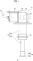
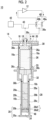
- Figs. 1 and 2 are views schematically showing a cryocooler 10 according to the embodiment.
- the cryocooler 10 is, for example, a two-stage type Gifford-McMahon (GM) cryocooler.
- Fig. 1 shows an appearance of the cryocooler 10
- Fig. 2 shows an internal structure of the cryocooler 10.
- the cryocooler 10 includes a compressor 12 and an expander 14.
- the compressor 12 is configured to collect a working gas of the cryocooler 10 from the expander 14, to pressurize the collected working gas, and to supply the working gas to the expander 14 again.
- the working gas is also called a refrigerant gas, and other suitable gases may be used although a helium gas is typically used.
- the expander 14 includes a cryocooler cylinder 16, a displacer assembly 18, and a cryocooler housing 20.
- the cryocooler housing 20 is coupled to the cryocooler cylinder 16, thereby forming a hermetic container that accommodates the displacer assembly 18.
- the internal volume of the cryocooler housing 20 may be connected to a low pressure side of the compressor 12 and be maintained at a low pressure.
- the cryocooler cylinder 16 includes a first cylinder 16a and a second cylinder 16b that extend in an axial direction.
- the first cylinder 16a and the second cylinder 16b each are, for example, a member that has a cylindrical shape, and the second cylinder 16b has a diameter smaller than the first cylinder 16a.
- the first cylinder 16a and the second cylinder 16b are coaxially disposed, and a lower end of the first cylinder 16a is strongly connected to an upper end of the second cylinder 16b.
- the displacer assembly 18 includes a first displacer 18a and a second displacer 18b.
- the first displacer 18a and the second displacer 18b each are, for example, a member that has a cylindrical shape, and the second displacer 18b has a diameter smaller than the first displacer 18a.
- the first displacer 18a and the second displacer 18b are coaxially disposed.
- the first displacer 18a is accommodated in the first cylinder 16a, and the second displacer 18b is accommodated in the second cylinder 16b.
- the first displacer 18a can reciprocate in the axial direction along the first cylinder 16a, and the second displacer 18b can reciprocate in the axial direction along the second cylinder 16b.
- the first displacer 18a and the second displacer 18b are connected to each other and move integrally.
- a side close to a top dead center of axial reciprocation of a displacer will be referred to as "up” and a side close to a bottom dead center will be referred to as "down".
- the top dead center is the position of the displacer at which the volume of an expansion space is maximized
- the bottom dead center is the position of the displacer at which the volume of the expansion space is minimized. Since a temperature gradient in which the temperature drops from an upper side to a lower side in the axial direction is generated during the operation of the cryocooler 10, the upper side can also be called a high temperature side and the lower side can also be called a low temperature side.
- the first displacer 18a accommodates a first regenerator 26.
- a tubular main body of the first displacer 18a is a first regenerator container extending in the axial direction.
- the first regenerator 26 is formed by filling the main body of the first displacer 18a with, for example, a wire mesh made of, such as copper, or other appropriate first regenerator material.
- An upper lid portion and a lower lid portion of the first displacer 18a may be provided as members separate from the main body of the first displacer 18a, or the first regenerator material may be accommodated in the first displacer 18a by fixing the upper lid portion and the lower lid portion of the first displacer 18a to the main body through appropriate means such as fastening and welding.
- the second displacer 18b accommodates a second regenerator 28.
- a tubular main body of the second displacer 18b is a second regenerator container extending in the axial direction.
- An upper lid portion and a lower lid portion of the second displacer 18b may be provided as members separate from the main body of the second displacer 18b, or a second regenerator material may be accommodated in the second displacer 18b by fixing the lower lid portion and the upper lid portion of the second displacer 18b to the main body through appropriate means such as fastening and welding.
- the lower lid portion of the second displacer 18b will be called a displacer cap 46.
- the second regenerator 28 includes at least two types of regenerator materials, in this example, three types of regenerator materials, and these regenerator materials are stacked in the axial direction of the second displacer 18b.
- the second regenerator 28 includes a non-magnetic regenerator material 28a, a metal-based magnetic regenerator material 28b, and a ceramic-based magnetic regenerator material 28c in order from the high temperature side to the low temperature side in the axial direction.
- materials having a great specific heat at different temperatures are selected as the regenerator materials.
- the non-magnetic regenerator material 28a is disposed on the high temperature side of the second displacer 18b, that is, adjacent to the upper lid portion of the second displacer 18b in the axial direction in the second displacer 18b.
- the non-magnetic regenerator material 28a may be formed of a material having a relatively high specific heat by volume (for example, a specific heat by volume higher than that of copper) at a temperature on the high temperature side of the second displacer 18b, for example, a temperature range of 10K to 50K or at least a part thereof.
- the non-magnetic regenerator material 28a may have a higher specific heat by volume than copper, which is a regenerator material typically used in the first displacer 18a, in this temperature range.
- the non-magnetic regenerator material 28a may have a higher specific heat by volume than a magnetic regenerator material (to be described later) in this temperature range.
- the non-magnetic regenerator material 28a may be formed of a non-magnetic metal material such as an alloy containing, for example, bismuth, zinc, lead, or at least one of these. Two types of materials may be stacked and used as the non-magnetic regenerator material 28a. For example, a regenerator material of zinc may be disposed adjacent to the upper lid portion of the second displacer 18b in the axial direction, and a regenerator material of bismuth may be disposed adjacent to the regenerator material of zinc in the axial direction.
- a regenerator material of zinc may be disposed adjacent to the upper lid portion of the second displacer 18b in the axial direction
- a regenerator material of bismuth may be disposed adjacent to the regenerator material of zinc in the axial direction.
- the metal-based magnetic regenerator material 28b is disposed in an intermediate portion of the second displacer 18b, that is, adjacent to the non-magnetic regenerator material 28a in the axial direction in the second displacer 18b.
- the metal-based magnetic regenerator material 28b may be formed of a material having a relatively high specific heat by volume at a temperature of an axial intermediate portion of the second displacer 18b, for example, a temperature range of 5K to 10K or at least a part thereof.
- the metal-based magnetic regenerator material 28b typically has a peak of the specific heat by volume associated with a magnetic phase transition in this temperature range.
- the metal-based magnetic regenerator material 28b may be formed of a metal magnetic material, such as HoCu 2 and Er 3 Ni.
- the ceramic-based magnetic regenerator material 28c is disposed in a low-temperature section of the second displacer 18b, that is, adjacent to the displacer cap 46 in the axial direction in the second displacer 18b.
- the ceramic-based magnetic regenerator material 28c is disposed between the metal-based magnetic regenerator material 28b and the displacer cap 46.
- the ceramic-based magnetic regenerator material 28c may be directly adjacent to the displacer cap 46.
- the ceramic-based magnetic regenerator material 28c and the displacer cap 46 may be adjacent to each other with a flow straightening layer interposed therebetween.
- the ceramic-based magnetic regenerator material 28c may be formed of a magnetic regenerator material having a relatively high specific heat by volume at a temperature on the low temperature side of the second displacer 18b (that is, a low temperature end of the displacer in which the temperature is the lowest in the displacer assembly 18), for example, a temperature range of 1K to 5K or at least a part thereof.
- the ceramic-based magnetic regenerator material 28c typically has a peak of the specific heat by volume associated with a magnetic phase transition in this temperature range.
- the ceramic-based magnetic regenerator material 28c may include at least one type of magnetic regenerator material represented by the general formula R x O 2 S or (R 1-y R' y ) x O 2 S (where R and R' are at least one type of rare earth element, 0.1 ⁇ x ⁇ 9, 0 ⁇ y ⁇ 1), or Gd x Al 2-x O 3 (1 ⁇ x ⁇ 2) .
- the rare earth elements R and R' may be, for example, yttrium Y, lanthanum La, cerium Ce, praseodymium Pr, neodymium Nd, promethium Pm, samarium Sm, europium Eu, gadolinium Gd, terbium Tb, dysprosium Dy, holmium Ho, erbium Er, thulium Tm, or ytterbium Yb.
- the ceramic-based magnetic regenerator material 28c may be Gd 2 O 2 S (also called GOS), Tb 2 O 2 S (also called TBOS) , (Gd i-yTby ) 2 O 2 S (0 ⁇ y ⁇ 1, also called GdTbOS), or GdAlO 3 (also called GAP) or may contain at least one type of these.
- the ceramic-based magnetic regenerator material 28c having such a composition has a higher (for example, several times higher) specific heat by volume in a temperature range of, for example, 1K to 5K or at least a part thereof, compared to a metal magnetic regenerator material such as HoCu 2 . Accordingly, the ceramic-based magnetic regenerator material 28c is suitable for increasing the cooling capacity of the cryocooler 10 that provides cryogenic cooling in this temperature range.
- an additive may be added to the magnetic regenerator material.
- the additive may be at least one type of zirconium Zr, aluminum Al, and alumina (Al 2 O 3 ).
- the weight ratio of the additive with respect to the magnetic regenerator material may be 20% or less or 15% or less. In this manner, the hardness of the magnetic regenerator material is increased without significantly changing the specific heat by volume of the magnetic regenerator material (that is, without significantly affecting the cooling capacity of the cryocooler 10), and the risk of damage and powdering caused by impact can be reduced.
- the non-magnetic regenerator material 28a, the metal-based magnetic regenerator material 28b, and the ceramic-based magnetic regenerator material 28c may be in a granular form.
- the granules forming such a granular regenerator material may be formed in a granular form having a size of, for example, 0.01 mm or more and 3 mm or less and may fill the second displacer 18b.
- the particle size of the granules may be 0.14 mm or more and 1.6 mm or less, preferably 0.15 mm or more and 1.4 mm or less, and more preferably 0.22 mm or more and 1.3 mm or less.
- the ratio of the granules having a particle size of 0.14 mm or more and 1.6 mm or less may be 70% by weight or more with respect to the total granules.
- the particle size is less than 0.14 mm, the density at the time of filling the regenerator is extremely high, and the passage resistance of the working gas (for example, a helium gas) may be rapidly increased.
- the working gas for example, a helium gas
- the ratio (aspect ratio) of a maximum diameter with respect to a minimum diameter of the granules is, in any three-dimensional direction, 5 or less, preferably 3 or less, and more preferably 2 or less. Furthermore, achieving a shape as close to a spherical shape as possible is preferable. In a case where the aspect ratio exceeds 5, deformation and fracture are likely to occur mechanically, and filling at a high density is difficult, so that the cooling efficiency is lowered. Accordingly, the ratio of the granules in which the ratio of the major axis to the minor axis is 5 or less may be 70% by weight or more with respect to the total granules.
- a surface thereof may be coated with a coating having a thickness of, for example, 1 to 50 um (for example, alumina (Al 2 O 3 ), a fluororesin, or the like).
- a partition member such as a wire mesh may be disposed at a boundary 29a between the non-magnetic regenerator material 28a and the metal-based magnetic regenerator material 28b.
- the partition member may be disposed at a boundary 29b between the metal-based magnetic regenerator material 28b and the ceramic-based magnetic regenerator material 28c.
- the displacer assembly 18 forms an upper chamber 30, a first expansion chamber 32, and a second expansion chamber 34 inside the cryocooler cylinder 16.
- the expander 14 includes a first cooling stage 33 and a second cooling stage 35.
- the cooling stage is also called a heat load flange in some cases.
- first cylinder 16a and the second cylinder 16b are formed of a material having a first thermal conductivity
- first cooling stage 33 and the second cooling stage 35 are formed of a material having a second thermal conductivity higher than the first thermal conductivity.
- first cylinder 16a and the second cylinder 16b may be formed of a metal material having a relatively low thermal conductivity, such as stainless steel
- first cooling stage 33 and the second cooling stage 35 may be formed of a metal material, such as copper (for example, pure copper such as oxygen-free copper and tough pitch copper) or other material having a high thermal conductivity.
- the upper chamber 30 is formed between the upper lid portion of the first displacer 18a and an upper portion of the first cylinder 16a.
- the first expansion chamber 32 is formed between the lower lid portion of the first displacer 18a and the first cooling stage 33.
- the first cooling stage 33 is fixed to a lower portion of the first cylinder 16a to surround the first expansion chamber 32.
- the second cooling stage 35 includes a stage end portion 35a and a stage tubular portion 35b that connects the stage end portion 35a to the second cylinder 16b in the axial direction.
- the second cooling stage 35 may be provided as a single component including the stage end portion 35a and the stage tubular portion 35b.
- the stage end portion 35a and the stage tubular portion 35b may be provided as separate members and may be connected to each other to form the second cooling stage 35.
- the second expansion chamber 34 is formed between the lower lid portion of the second displacer 18b, that is, the displacer cap 46 and the second cooling stage 35. More specifically, the displacer cap 46 faces the stage end portion 35a with the second expansion chamber 34 interposed therebetween, and the stage tubular portion 35b is fixed to a lower portion of the second cylinder 16b to surround the second expansion chamber 34.
- the first regenerator 26 is connected to the upper chamber 30 through a working gas flow path 36a formed in the upper lid portion of the first displacer 18a and is connected to the first expansion chamber 32 through a working gas flow path 36b formed in the lower lid portion of the first displacer 18a.
- the second regenerator 28 is connected to the first regenerator 26 through a working gas flow path 36c formed from the lower lid portion of the first displacer 18a to the upper lid portion of the second displacer 18b.
- the second regenerator 28 is connected to the second expansion chamber 34 through a working gas flow path 36d formed in the displacer cap 46.
- the working gas flow path 36d may include an axial flow path 36d1 and a radial flow path 36d2.
- the axial flow path 36d1 extends axially downward from a lower end of the ceramic-based magnetic regenerator material 28c in the axial direction inside the displacer cap 46.
- the radial flow path 36d2 extends in a radial direction from a lower end of the axial flow path 36d1 inside the displacer cap 46.
- the radial flow path 36d2 is directed to the stage tubular portion 35b of the second cooling stage 35.
- a plurality of radial flow paths 36d2 may extend from the axial flow path 36d1.
- the working gas that has entered the axial flow path 36d1 from the ceramic-based magnetic regenerator material 28c is blown from the radial flow paths 36d2 toward the stage tubular portion 35b and flows into the second expansion chamber 34 through a radial clearance between the displacer cap 46 and the stage tubular portion 35b.
- a working gas flow between the first expansion chamber 32, the second expansion chamber 34, and the upper chamber 30 is not a clearance between the cryocooler cylinder 16 and the displacer assembly 18, and a first seal 38a and a second seal 38b may be provided in order to guide the working gas flow to the first regenerator 26 and the second regenerator 28.
- the first seal 38a may be mounted on the upper lid portion of the first displacer 18a to be disposed between the first displacer 18a and the first cylinder 16a.
- the second seal 38b may be mounted on the upper lid portion of the second displacer 18b to be disposed between the second displacer 18b and the second cylinder 16b.
- the expander 14 includes a pressure switching valve 40 and a driving motor 42.
- the pressure switching valve 40 is accommodated in the cryocooler housing 20, and the driving motor 42 is attached to the cryocooler housing 20.
- the pressure switching valve 40 is configured to include a high pressure valve 40a and a low pressure valve 40b and to generate periodic pressure fluctuations in the cryocooler cylinder 16.
- a working gas discharge port of the compressor 12 is connected to the upper chamber 30 via the high pressure valve 40a, and a working gas suction port of the compressor 12 is connected to the upper chamber 30 via the low pressure valve 40b.
- the high pressure valve 40a and the low pressure valve 40b are configured to open and close selectively and alternately (that is, such that when one is open, the other is closed).
- a high pressure (for example, 2 to 3 MPa) working gas is supplied from the compressor 12 to the expander 14 through the high pressure valve 40a, and a low pressure (for example, 0.5 to 1.5 MPa) working gas is collected from the expander 14 to the compressor 12 through the low pressure valve 40b.
- a direction in which the working gas flows is shown with arrows in Fig. 2 .
- the driving motor 42 is provided to drive reciprocation of the displacer assembly 18.
- the driving motor 42 is connected to a displacer drive shaft 44 via a motion conversion mechanism 43 such as a Scotch yoke mechanism.
- the motion conversion mechanism 43 is accommodated in the cryocooler housing 20 like the pressure switching valve 40.
- the displacer drive shaft 44 extends from the motion conversion mechanism 43 into the upper chamber 30 through the cryocooler housing 20 and is fixed to the upper lid portion of the first displacer 18a.
- a third seal 38c is provided in order to prevent leakage of the working gas from the upper chamber 30 to the cryocooler housing 20 (which is maintained at a low pressure in some cases as described above).
- the third seal 38c may be mounted on the cryocooler housing 20 to be disposed between the cryocooler housing 20 and the displacer drive shaft 44.
- the driving motor 42 When the driving motor 42 is driven, a rotational output of the driving motor 42 is converted into axial reciprocation of the displacer drive shaft 44 by the motion conversion mechanism 43, and the displacer assembly 18 reciprocates in the cryocooler cylinder 16 in the axial direction.
- the driving motor 42 is connected to the high pressure valve 40a and the low pressure valve 40b to selectively and alternately open and close these valves.
- the cryocooler 10 When the compressor 12 and the driving motor 42 are operated, the cryocooler 10 generates periodic volume fluctuations in the first expansion chamber 32 and the second expansion chamber 34 and pressure fluctuations of the working gas synchronized therewith, thereby forming a refrigeration cycle, and the first cooling stage 33 and the second cooling stage 35 are cooled to a desired cryogenic temperature.
- the first cooling stage 33 may be cooled to a first cooling temperature in a range of, for example, approximately 30K to approximately 80K.
- the second cooling stage 35 may be cooled to a second cooling temperature lower than the first cooling temperature, for example, 1K to 20K.
- the second cooling temperature may be a liquid helium temperature of approximately 4.2K or a temperature lower than the liquid helium temperature.
- Fig. 3 is a graph showing a temperature change of specific heat of a representative magnetic regenerator material, and more specifically, is a graph showing a temperature change of specific heat of HoCu 2 and GOS in a cryogenic temperature region.
- HoCu 2 and GOS have a peak at which the specific heat is maximized in a range in which a temperature is approximately 4K to approximately 10K, that is, a temperature range of a region of the second regenerator 28 in which HoCu 2 or GOS is accommodated.
- the specific heat of HoCu 2 is maximized at two locations where the temperature is approximately 6K and approximately 9K.
- the specific heat of GOS has an extremely sharp peak at approximately 5K.
- Other types of ceramic-based magnetic regenerator materials also have a sharp peak at a specific temperature of approximately 5K or less, as in GOS.
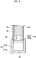
- Fig. 4 is a view schematically showing a part of a cryocooler according to a comparative example.
- Fig. 4 shows a lowest temperature section of the cryocooler, that is, a second cooling stage 135, a low temperature side of a second cylinder 116b extending upward in the axial direction from the second cooling stage 135, and a low temperature side of a second displacer 118b including a displacer cap 146.
- the second cooling stage 135 includes a terminal end portion 135a and a tubular portion 135b connecting the terminal end portion 135a to the second cylinder 116b in the axial direction.
- a magnetic regenerator material for example, a ceramic-based magnetic regenerator material 128c is accommodated on the low temperature side of the second displacer 118b.
- the ceramic-based magnetic regenerator material 128c and a second expansion chamber 134 are connected to each other through the working gas flow path 136d.
- the second displacer 118b is positioned at the top dead center. Accordingly, the displacer cap 146 is located at its uppermost position in the axial direction, and the second expansion chamber 134 takes a maximum volume.
- an axial position of the radial flow path 136d2 of the working gas flow path 136d is the same as an axial upper end of the tubular portion 135b of the second cooling stage 135 (or an axial lower end of the second cylinder 116b). In this manner, axial heights of the radial flow path 136d2 and an upper end portion of the tubular portion 135b of the second cooling stage 135 are aligned.
- the ceramic-based magnetic regenerator material 128c adjacent to an upper side of the displacer cap 146 in the axial direction is positioned above the tubular portion 135b of the second cooling stage 135 in the axial direction and is surrounded by the second cylinder 116b when the second displacer 118b is positioned at the top dead center.
- the ceramic-based magnetic regenerator material 128c is positioned outside a space 148 surrounded by the second cooling stage 135, which is shown by a broken line in Fig. 4 .
- the displacer cap 146 and a lower end portion of the ceramic-based magnetic regenerator material 128c adjacent thereto are at the lowest temperature in the cryocooler, as in the second cooling stage 135.
- an axial temperature distribution in which the temperature becomes higher as going upward in the axial direction is formed in the second cylinder 116b.
- a portion of the second cylinder 116b surrounding the ceramic-based magnetic regenerator material 128c has a temperature somewhat higher than that of the ceramic-based magnetic regenerator material 128c when the second displacer 118b is at the top dead center.
- the specific heat of the ceramic-based magnetic regenerator material 128c is extremely sensitive to temperature.
- a temperature fluctuation in the ceramic-based magnetic regenerator material 128c may cause a significant fluctuation of the specific heat, for example, a substantial decrease, even if the decrease is slight. Consequently, in the cryocooler of the comparative example, the cryogenic performance of the ceramic-based magnetic regenerator material 128c, and ultimately the performance of the cryocooler may be affected.
- Figs. 5A and 5B are views schematically showing axial reciprocation of the displacer assembly 18 according to the embodiment.
- Fig. 5A schematically shows the expander 14 when the displacer assembly 18 is positioned at the top dead center
- Fig. 5B schematically shows the expander 14 when the displacer assembly 18 is positioned at the bottom dead center.
- the displacer assembly 18 is at an intermediate position between the top dead center and the bottom dead center.
- each of the first expansion chamber 32 and the second expansion chamber 34 has its maximum volume
- each of the first expansion chamber 32 and the second expansion chamber 34 has its minimum volume.
- An axial clearance between the first displacer 18a and the first cooling stage 33 when the first displacer 18a is at the bottom dead center is ideally zero.
- an axial clearance of approximately 0.1 mm to approximately 1 mm is set in order to avoid contact between the two.
- an axial clearance between the second displacer 18b and the stage end portion 35a of the second cooling stage 35 when the second displacer 18b is at the bottom dead center may be set within a range of, for example, approximately 0.1 mm to approximately 1 mm.
- the upper chamber 30 has a minimum volume when the first displacer 18a is at the top dead center and has a maximum volume when the first displacer 18a is at the bottom dead center.
- the axial height of the upper chamber 30 when the first displacer 18a is at the top dead center, that is, an axial clearance between the cryocooler housing 20 and the first displacer 18a is ideally zero and may be set, for example, within a range of approximately 0.1 mm to approximately 1 mm in practice. Accordingly, a dead volume in the upper chamber 30 can be minimized.
- the axial position of the ceramic-based magnetic regenerator material 28c in the second displacer 18b is determined to overlap the stage tubular portion 35b in the axial direction when the second displacer 18b is at the top dead center. Accordingly, when the second displacer 18b is positioned at the top dead center, at least a part of the ceramic-based magnetic regenerator material 28c, for example, an axially lower portion of the ceramic-based magnetic regenerator material 28c is positioned below an upper end 50 of the stage tubular portion 35b of the second cooling stage 35 in the axial direction and is surrounded by the stage tubular portion 35b. Similarly, the displacer cap 46 is also surrounded by the stage tubular portion 35b.
- a lower end portion of the second displacer 18b that is, at least a part of the ceramic-based magnetic regenerator material 28c and the displacer cap 46 are positioned in a space 48 surrounded by the second cooling stage 35, which is shown by a broken line in Fig. 5A .
- the second displacer 18b when the second displacer 18b is at the bottom dead center, as shown in Fig. 5B , the second displacer 18b further enters the space 48 surrounded by the second cooling stage 35. At the bottom dead center of the second displacer 18b, more portions of the ceramic-based magnetic regenerator material 28c are surrounded by the stage tubular portion 35b together with the displacer cap 46 and are positioned in the space 48.
- the axial position of the ceramic-based magnetic regenerator material 28c in the second displacer 18b when the second displacer 18b is at the top dead center is determined to overlap the stage tubular portion 35b in the axial direction. Consequently, at least a part of the ceramic-based magnetic regenerator material 28c is held in the space 48 surrounded by the second cooling stage 35 over an entire stroke length S of axial reciprocation of the second displacer 18b.
- the displacer cap 46 and a lower end portion of the ceramic-based magnetic regenerator material 28c adjacent thereto are at the lowest temperature in the cryocooler, as in the second cooling stage 35. Therefore, unlike the comparative example shown in Fig. 4 , in this embodiment, the ceramic-based magnetic regenerator material 28c can stabilize the temperature by being surrounded by the second cooling stage 35. Accordingly, an increase in an effect on the cryogenic performance depending on a temperature fluctuation that may occur in the ceramic-based magnetic regenerator material 28c and ultimately on the performance of the cryocooler 10 can be suppressed.
- the axial position of the metal-based magnetic regenerator material 28b in the second displacer 18b is determined not to overlap the stage tubular portion 35b in the axial direction when the second displacer 18b is at the top dead center. Accordingly, when the second displacer 18b is positioned at the top dead center, as shown in Fig. 5A , the metal-based magnetic regenerator material 28b is positioned above the stage tubular portion 35b in the axial direction and is surrounded by the second cylinder 16b. In this manner, at the top dead center of the second displacer 18b, the metal-based magnetic regenerator material 28b is positioned outside the space 48 surrounded by the second cooling stage 35.
- the cryocooler 10 is used under a strong magnetic field in some cases, such as an application of cooling a superconducting magnet.
- a strong magnetic field such as an application of cooling a superconducting magnet.
- the metal-based magnetic regenerator material 28b moves in a magnetic field distribution, an eddy current is induced inside the metal-based magnetic regenerator material 28b, and the eddy current may be converted into heat by a resistance of the metal-based magnetic regenerator material 28b itself. Therefore, the metal-based magnetic regenerator material 28b is disposed at a location separated away from the second cooling stage 35 in the axial direction. Consequently, a temperature rise of the second cooling stage 35 caused by heat generation of the metal-based magnetic regenerator material 28b can be suppressed.
- the metal-based magnetic regenerator material 28b may have an axial position in the second displacer 18b which is determined not to overlap the stage tubular portion 35b in the axial direction when the second displacer 18b is at the bottom dead center. Accordingly, when the second displacer 18b is positioned at the bottom dead center, as shown in Fig. 5B , the metal-based magnetic regenerator material 28b may be positioned above the stage tubular portion 35b in the axial direction, may be surrounded by the second cylinder 16b, and may be positioned outside the space 48.
- the axial position of the ceramic-based magnetic regenerator material 28c in the second displacer 18b may be determined so that, when the stroke length of reciprocation of the second displacer 18b in the axial direction is denoted by S, the axial height of the displacer cap 46 is denoted by Hc, and an axial height from the displacer cap 46 to an upper end (that is, the boundary 29b) of the ceramic-based magnetic regenerator material 28c is denoted by Hs, Hs > S - Hc is satisfied.
- the metal-based magnetic regenerator material 28b is held outside the space 48 surrounded by the second cooling stage 35 over the entire stroke length S of axial reciprocation of the second displacer 18b. Therefore, a temperature rise of the second cooling stage 35 caused by heat generation of the metal-based magnetic regenerator material 28b can be suppressed.
- the speed of axial reciprocation of the second displacer 18b is slow in the vicinity of the top dead center and the bottom dead center and is fast in the axial intermediate portion.
- the axial intermediate portion is, for example, in a range of 1/4 to 3/4 of the stroke length S. Therefore, in order to dispose the metal-based magnetic regenerator material 28b to avoid this range, the axial position of the ceramic-based magnetic regenerator material 28c in the second displacer 18b may be determined to satisfy Hs > (3/4)S - Hc.
- the displacer cap 46 may be formed of a material having a high electrical resistivity compared to the second cooling stage 35. In this manner, when the second displacer 18b moves in a magnetic field distribution, an eddy current that may be induced inside the displacer cap 46 can be reduced, and heat generation from the displacer cap 46 caused by the eddy current can also be reduced.
- the second cooling stage 35 is typically formed of copper as described above.
- the displacer cap 46 may be formed of a metal having a higher electrical resistivity than that of copper, for example, stainless steel, a nickel alloy such as nichrome and Inconel (registered trademark), and a titanium alloy.
- the displacer cap 46 may be formed of, for example, a synthetic resin material such as a phenol resin.
- the displacer cap 46 may be formed of, for example, a ceramic-based magnetic regenerator material such as GOS.
- Fig. 6 is a view schematically showing an example of the displacer cap 46 according to the embodiment.
- the displacer cap 46 may include a main body 46a and a regenerator body 46b.
- the main body 46a may be formed of a material having a high electrical resistivity compared to the second cooling stage 35, such as stainless steel.
- the working gas flow path 36d may be formed in the main body 46a.
- the regenerator body 46b may be formed of a ceramic-based magnetic regenerator material, such as GOS. In this manner, as the displacer cap 46 is provided with the regenerator body 46b, a temperature rise of the displacer cap 46 can be suppressed and stabilized.
- the regenerator body 46b may be exposed to the second expansion chamber 34.
- the regenerator body 46b may be fixed to an outer surface of the displacer cap 46 to face the stage end portion 35a.
- the main body 46a may have a recess that receives the regenerator body 46b, and the regenerator body 46b may be bonded to the main body 46a using a cryogenic adhesive such as Nitofix (registered trademark).
- a screw may be formed on an outer peripheral surface of the regenerator body 46b, a screw hole, which corresponds to the main body 46a, may be formed, and the regenerator body 46b may be screwed and fixed into the screw hole of the main body 46a.
- cryocooler 10 may be another type of cryocooler, such as a solvay cryocooler, in which a displacer in which a ceramic-based magnetic regenerator material is built reciprocates in the axial direction.
Landscapes
- Engineering & Computer Science (AREA)
- Physics & Mathematics (AREA)
- Mechanical Engineering (AREA)
- Thermal Sciences (AREA)
- General Engineering & Computer Science (AREA)
- Chemical & Material Sciences (AREA)
- Combustion & Propulsion (AREA)
- Containers, Films, And Cooling For Superconductive Devices (AREA)
Abstract
A performance decrease of a cryocooler (10) in which a ceramic-based magnetic regenerator material (28c) is built is suppressed.A cryocooler (10) includes a second cylinder (16b) that has a first thermal conductivity and that extends in an axial direction, a second cooling stage (35) that has a second thermal conductivity higher than the first thermal conductivity and that includes a stage end portion (35a) and a stage tubular portion (35b) connecting the stage end portion (35a) to the second cylinder (16b) in the axial direction, a second displacer (18b) that is capable of reciprocating in the axial direction in the second cylinder (16b), that forms a second expansion chamber (34) with the stage end portion (35a), and in which the second expansion chamber (34) takes a maximum volume at a top dead center, and a ceramic-based magnetic regenerator material (28c) that is accommodated in the second displacer (18b) and of which an axial position in the second displacer (18b) is determined to overlap the stage tubular portion (35b) in the axial direction when the second displacer (18b) is at the top dead center.
Description
- The present invention relates to a cryocooler.
- In general, on a cryocooler that provides cooling to a cryogenic temperature of approximately 10K or less (for example, a liquid helium temperature of approximately 4.2K), a regenerator including a magnetic regenerator material having a great specific heat peak associated with a magnetic phase transition in this temperature range is mounted. The magnetic regenerator material is useful in improving the cooling capacity of the cryocooler at such a cryogenic temperature. There are two types of magnetic regenerator materials, and a metal-based magnetic regenerator material such as HoCu2 and a ceramic-based magnetic regenerator material such as Gd2O2S (also called GOS) are known (for example,
Japanese Unexamined Patent Publication No. 2015-183970 - For example, in a cryocooler in which a displacer in which a regenerator material is built moves in an axial direction, such as a Gifford-McMahon (GM) cryocooler, the temperature of the regenerator material may slightly fluctuate with the axial movement of the displacer by being affected by an axial temperature distribution generated in the cryocooler itself. In many ceramic-based magnetic regenerator materials including GOS, specific heat is considerably sensitive to temperature, that is, a specific heat peak is extremely sharp. For this reason, a temperature fluctuation in the ceramic-based magnetic regenerator material may lead to, even if the fluctuation is slight, a significant fluctuation of the specific heat, for example, a substantial decrease. Accordingly, the cryogenic performance of the ceramic-based magnetic regenerator material and ultimately the performance of the cryocooler may be affected.
- An exemplary object of one aspect of the present invention is to suppress a performance decrease of a cryocooler in which a ceramic-based magnetic regenerator material is built.
- According to an aspect of the present invention, there is provided a cryocooler including a cylinder that has a first thermal conductivity and that extends in an axial direction, a cooling stage that has a second thermal conductivity higher than the first thermal conductivity and that includes a stage end portion and a stage tubular portion connecting the stage end portion to the cylinder in the axial direction, a displacer that is capable of reciprocating in the axial direction in the cylinder, that forms an expansion space with the stage end portion, and in which the expansion space takes a maximum volume at a top dead center, and a ceramic-based magnetic regenerator material that is accommodated in the displacer and of which an axial position in the displacer is determined to overlap the stage tubular portion in the axial direction when the displacer is at the top dead center.
- With the present invention, a performance decrease of the cryocooler in which the ceramic-based magnetic regenerator material is built can be suppressed.
-
-
Fig. 1 is a view schematically showing a cryocooler according to an embodiment. -
Fig. 2 is a view schematically showing the cryocooler according to the embodiment. -
Fig. 3 is a graph showing a temperature change of specific heat of a representative magnetic regenerator material. -
Fig. 4 is a view schematically showing a part of a cryocooler according to a comparative example. -
Figs. 5A and 5B are views schematically showing axial reciprocation of a displacer assembly according to the embodiment. -
Fig. 6 is a view schematically showing an example of a displacer cap according to the embodiment. - Hereinafter, an embodiment for carrying out the present invention will be described in detail with reference to the drawings. In the description and drawings, the same or equivalent components, members, and processing will be assigned with the same reference symbols, and redundant description thereof will be omitted as appropriate. The scales and shapes of shown parts are set for convenience in order to make the description easy to understand and are not to be understood as limiting unless stated otherwise. The embodiment is merely an example and does not limit the scope of the present invention. All characteristics and combinations to be described in the embodiment are not necessarily essential to the invention.
-
Figs. 1 and2 are views schematically showing acryocooler 10 according to the embodiment. Thecryocooler 10 is, for example, a two-stage type Gifford-McMahon (GM) cryocooler.Fig. 1 shows an appearance of thecryocooler 10, andFig. 2 shows an internal structure of thecryocooler 10. - The
cryocooler 10 includes acompressor 12 and anexpander 14. Thecompressor 12 is configured to collect a working gas of thecryocooler 10 from theexpander 14, to pressurize the collected working gas, and to supply the working gas to theexpander 14 again. The working gas is also called a refrigerant gas, and other suitable gases may be used although a helium gas is typically used. - The
expander 14 includes acryocooler cylinder 16, adisplacer assembly 18, and acryocooler housing 20. Thecryocooler housing 20 is coupled to thecryocooler cylinder 16, thereby forming a hermetic container that accommodates thedisplacer assembly 18. The internal volume of thecryocooler housing 20 may be connected to a low pressure side of thecompressor 12 and be maintained at a low pressure. - The
cryocooler cylinder 16 includes afirst cylinder 16a and asecond cylinder 16b that extend in an axial direction. Thefirst cylinder 16a and thesecond cylinder 16b each are, for example, a member that has a cylindrical shape, and thesecond cylinder 16b has a diameter smaller than thefirst cylinder 16a. Thefirst cylinder 16a and thesecond cylinder 16b are coaxially disposed, and a lower end of thefirst cylinder 16a is strongly connected to an upper end of thesecond cylinder 16b. - As shown in
Fig. 2 , thedisplacer assembly 18 includes afirst displacer 18a and asecond displacer 18b. Thefirst displacer 18a and thesecond displacer 18b each are, for example, a member that has a cylindrical shape, and thesecond displacer 18b has a diameter smaller than thefirst displacer 18a. Thefirst displacer 18a and thesecond displacer 18b are coaxially disposed. - The
first displacer 18a is accommodated in thefirst cylinder 16a, and thesecond displacer 18b is accommodated in thesecond cylinder 16b. Thefirst displacer 18a can reciprocate in the axial direction along thefirst cylinder 16a, and thesecond displacer 18b can reciprocate in the axial direction along thesecond cylinder 16b. Thefirst displacer 18a and thesecond displacer 18b are connected to each other and move integrally. - In the present specification, in order to describe a positional relationship between components of the
cryocooler 10, for convenience of description, a side close to a top dead center of axial reciprocation of a displacer will be referred to as "up" and a side close to a bottom dead center will be referred to as "down". The top dead center is the position of the displacer at which the volume of an expansion space is maximized, and the bottom dead center is the position of the displacer at which the volume of the expansion space is minimized. Since a temperature gradient in which the temperature drops from an upper side to a lower side in the axial direction is generated during the operation of thecryocooler 10, the upper side can also be called a high temperature side and the lower side can also be called a low temperature side. - The
first displacer 18a accommodates afirst regenerator 26. A tubular main body of thefirst displacer 18a is a first regenerator container extending in the axial direction. Thefirst regenerator 26 is formed by filling the main body of thefirst displacer 18a with, for example, a wire mesh made of, such as copper, or other appropriate first regenerator material. An upper lid portion and a lower lid portion of thefirst displacer 18a may be provided as members separate from the main body of thefirst displacer 18a, or the first regenerator material may be accommodated in thefirst displacer 18a by fixing the upper lid portion and the lower lid portion of thefirst displacer 18a to the main body through appropriate means such as fastening and welding. - Similarly, the
second displacer 18b accommodates asecond regenerator 28. A tubular main body of thesecond displacer 18b is a second regenerator container extending in the axial direction. An upper lid portion and a lower lid portion of thesecond displacer 18b may be provided as members separate from the main body of thesecond displacer 18b, or a second regenerator material may be accommodated in thesecond displacer 18b by fixing the lower lid portion and the upper lid portion of thesecond displacer 18b to the main body through appropriate means such as fastening and welding. Hereinafter, for convenience of description, the lower lid portion of thesecond displacer 18b will be called adisplacer cap 46. - The
second regenerator 28 includes at least two types of regenerator materials, in this example, three types of regenerator materials, and these regenerator materials are stacked in the axial direction of thesecond displacer 18b. As shown inFig. 2 , thesecond regenerator 28 includes anon-magnetic regenerator material 28a, a metal-basedmagnetic regenerator material 28b, and a ceramic-basedmagnetic regenerator material 28c in order from the high temperature side to the low temperature side in the axial direction. In order to increase the cooling capacity of a second stage of thecryocooler 10, materials having a great specific heat at different temperatures are selected as the regenerator materials. - The
non-magnetic regenerator material 28a is disposed on the high temperature side of thesecond displacer 18b, that is, adjacent to the upper lid portion of thesecond displacer 18b in the axial direction in thesecond displacer 18b. Thenon-magnetic regenerator material 28a may be formed of a material having a relatively high specific heat by volume (for example, a specific heat by volume higher than that of copper) at a temperature on the high temperature side of thesecond displacer 18b, for example, a temperature range of 10K to 50K or at least a part thereof. As described above, thenon-magnetic regenerator material 28a may have a higher specific heat by volume than copper, which is a regenerator material typically used in thefirst displacer 18a, in this temperature range. In addition, thenon-magnetic regenerator material 28a may have a higher specific heat by volume than a magnetic regenerator material (to be described later) in this temperature range. - The
non-magnetic regenerator material 28a may be formed of a non-magnetic metal material such as an alloy containing, for example, bismuth, zinc, lead, or at least one of these. Two types of materials may be stacked and used as thenon-magnetic regenerator material 28a. For example, a regenerator material of zinc may be disposed adjacent to the upper lid portion of thesecond displacer 18b in the axial direction, and a regenerator material of bismuth may be disposed adjacent to the regenerator material of zinc in the axial direction. - The metal-based
magnetic regenerator material 28b is disposed in an intermediate portion of thesecond displacer 18b, that is, adjacent to thenon-magnetic regenerator material 28a in the axial direction in thesecond displacer 18b. The metal-basedmagnetic regenerator material 28b may be formed of a material having a relatively high specific heat by volume at a temperature of an axial intermediate portion of thesecond displacer 18b, for example, a temperature range of 5K to 10K or at least a part thereof. The metal-basedmagnetic regenerator material 28b typically has a peak of the specific heat by volume associated with a magnetic phase transition in this temperature range. The metal-basedmagnetic regenerator material 28b may be formed of a metal magnetic material, such as HoCu2 and Er3Ni. - The ceramic-based
magnetic regenerator material 28c is disposed in a low-temperature section of thesecond displacer 18b, that is, adjacent to thedisplacer cap 46 in the axial direction in thesecond displacer 18b. The ceramic-basedmagnetic regenerator material 28c is disposed between the metal-basedmagnetic regenerator material 28b and thedisplacer cap 46. The ceramic-basedmagnetic regenerator material 28c may be directly adjacent to thedisplacer cap 46. Alternatively, the ceramic-basedmagnetic regenerator material 28c and thedisplacer cap 46 may be adjacent to each other with a flow straightening layer interposed therebetween. - The ceramic-based
magnetic regenerator material 28c may be formed of a magnetic regenerator material having a relatively high specific heat by volume at a temperature on the low temperature side of thesecond displacer 18b (that is, a low temperature end of the displacer in which the temperature is the lowest in the displacer assembly 18), for example, a temperature range of 1K to 5K or at least a part thereof. The ceramic-basedmagnetic regenerator material 28c typically has a peak of the specific heat by volume associated with a magnetic phase transition in this temperature range. - The ceramic-based
magnetic regenerator material 28c may include at least one type of magnetic regenerator material represented by the general formula RxO2S or (R1-yR'y)xO2S (where R and R' are at least one type of rare earth element, 0.1 ≤ x ≤ 9, 0 < y < 1), or GdxAl2-xO3 (1 ≤ x < 2) . The rare earth elements R and R' may be, for example, yttrium Y, lanthanum La, cerium Ce, praseodymium Pr, neodymium Nd, promethium Pm, samarium Sm, europium Eu, gadolinium Gd, terbium Tb, dysprosium Dy, holmium Ho, erbium Er, thulium Tm, or ytterbium Yb. - Accordingly, the ceramic-based
magnetic regenerator material 28c may be Gd2O2S (also called GOS), Tb2O2S (also called TBOS) , (Gdi-yTby)2O2S (0 < y < 1, also called GdTbOS), or GdAlO3 (also called GAP) or may contain at least one type of these. - As is known, the ceramic-based
magnetic regenerator material 28c having such a composition has a higher (for example, several times higher) specific heat by volume in a temperature range of, for example, 1K to 5K or at least a part thereof, compared to a metal magnetic regenerator material such as HoCu2. Accordingly, the ceramic-basedmagnetic regenerator material 28c is suitable for increasing the cooling capacity of thecryocooler 10 that provides cryogenic cooling in this temperature range. - In order to improve the mechanical strength of the magnetic regenerator material, an additive may be added to the magnetic regenerator material. For example, the additive may be at least one type of zirconium Zr, aluminum Al, and alumina (Al2O3). For example, the weight ratio of the additive with respect to the magnetic regenerator material may be 20% or less or 15% or less. In this manner, the hardness of the magnetic regenerator material is increased without significantly changing the specific heat by volume of the magnetic regenerator material (that is, without significantly affecting the cooling capacity of the cryocooler 10), and the risk of damage and powdering caused by impact can be reduced.
- The
non-magnetic regenerator material 28a, the metal-basedmagnetic regenerator material 28b, and the ceramic-basedmagnetic regenerator material 28c may be in a granular form. The granules forming such a granular regenerator material may be formed in a granular form having a size of, for example, 0.01 mm or more and 3 mm or less and may fill thesecond displacer 18b. For example, the particle size of the granules may be 0.14 mm or more and 1.6 mm or less, preferably 0.15 mm or more and 1.4 mm or less, and more preferably 0.22 mm or more and 1.3 mm or less. The ratio of the granules having a particle size of 0.14 mm or more and 1.6 mm or less may be 70% by weight or more with respect to the total granules. In a case where the particle size is less than 0.14 mm, the density at the time of filling the regenerator is extremely high, and the passage resistance of the working gas (for example, a helium gas) may be rapidly increased. In addition, in a case where the particle size exceeds 1.6 mm, there is a concern that heat exchange efficiency between the granules and the working gas may be significantly lowered. - In addition, the ratio (aspect ratio) of a maximum diameter with respect to a minimum diameter of the granules is, in any three-dimensional direction, 5 or less, preferably 3 or less, and more preferably 2 or less.. Furthermore, achieving a shape as close to a spherical shape as possible is preferable. In a case where the aspect ratio exceeds 5, deformation and fracture are likely to occur mechanically, and filling at a high density is difficult, so that the cooling efficiency is lowered. Accordingly, the ratio of the granules in which the ratio of the major axis to the minor axis is 5 or less may be 70% by weight or more with respect to the total granules.
- In order to protect the granules, a surface thereof may be coated with a coating having a thickness of, for example, 1 to 50 um (for example, alumina (Al2O3), a fluororesin, or the like).
- In order to separate the
non-magnetic regenerator material 28a and the metal-basedmagnetic regenerator material 28b, a partition member such as a wire mesh may be disposed at aboundary 29a between thenon-magnetic regenerator material 28a and the metal-basedmagnetic regenerator material 28b. In addition, if necessary, the partition member may be disposed at aboundary 29b between the metal-basedmagnetic regenerator material 28b and the ceramic-basedmagnetic regenerator material 28c. - The
displacer assembly 18 forms anupper chamber 30, afirst expansion chamber 32, and asecond expansion chamber 34 inside thecryocooler cylinder 16. In order to exchange heat with a desired object or medium to be cooled by thecryocooler 10, theexpander 14 includes afirst cooling stage 33 and asecond cooling stage 35. The cooling stage is also called a heat load flange in some cases. - While the
first cylinder 16a and thesecond cylinder 16b are formed of a material having a first thermal conductivity, thefirst cooling stage 33 and thesecond cooling stage 35 are formed of a material having a second thermal conductivity higher than the first thermal conductivity. For example, thefirst cylinder 16a and thesecond cylinder 16b may be formed of a metal material having a relatively low thermal conductivity, such as stainless steel, and thefirst cooling stage 33 and thesecond cooling stage 35 may be formed of a metal material, such as copper (for example, pure copper such as oxygen-free copper and tough pitch copper) or other material having a high thermal conductivity. - The
upper chamber 30 is formed between the upper lid portion of thefirst displacer 18a and an upper portion of thefirst cylinder 16a. Thefirst expansion chamber 32 is formed between the lower lid portion of thefirst displacer 18a and thefirst cooling stage 33. Thefirst cooling stage 33 is fixed to a lower portion of thefirst cylinder 16a to surround thefirst expansion chamber 32. - The
second cooling stage 35 includes astage end portion 35a and astage tubular portion 35b that connects thestage end portion 35a to thesecond cylinder 16b in the axial direction. Thesecond cooling stage 35 may be provided as a single component including thestage end portion 35a and thestage tubular portion 35b. Alternatively, thestage end portion 35a and thestage tubular portion 35b may be provided as separate members and may be connected to each other to form thesecond cooling stage 35. - The
second expansion chamber 34 is formed between the lower lid portion of thesecond displacer 18b, that is, thedisplacer cap 46 and thesecond cooling stage 35. More specifically, thedisplacer cap 46 faces thestage end portion 35a with thesecond expansion chamber 34 interposed therebetween, and thestage tubular portion 35b is fixed to a lower portion of thesecond cylinder 16b to surround thesecond expansion chamber 34. - The
first regenerator 26 is connected to theupper chamber 30 through a workinggas flow path 36a formed in the upper lid portion of thefirst displacer 18a and is connected to thefirst expansion chamber 32 through a workinggas flow path 36b formed in the lower lid portion of thefirst displacer 18a. Thesecond regenerator 28 is connected to thefirst regenerator 26 through a workinggas flow path 36c formed from the lower lid portion of thefirst displacer 18a to the upper lid portion of thesecond displacer 18b. In addition, thesecond regenerator 28 is connected to thesecond expansion chamber 34 through a workinggas flow path 36d formed in thedisplacer cap 46. - The working
gas flow path 36d may include an axial flow path 36d1 and a radial flow path 36d2. The axial flow path 36d1 extends axially downward from a lower end of the ceramic-basedmagnetic regenerator material 28c in the axial direction inside thedisplacer cap 46. The radial flow path 36d2 extends in a radial direction from a lower end of the axial flow path 36d1 inside thedisplacer cap 46. The radial flow path 36d2 is directed to thestage tubular portion 35b of thesecond cooling stage 35. In order to uniformly blow the working gas from thedisplacer cap 46 in a circumferential direction, a plurality of radial flow paths 36d2 may extend from the axial flow path 36d1. Accordingly, the working gas that has entered the axial flow path 36d1 from the ceramic-basedmagnetic regenerator material 28c is blown from the radial flow paths 36d2 toward thestage tubular portion 35b and flows into thesecond expansion chamber 34 through a radial clearance between thedisplacer cap 46 and thestage tubular portion 35b. - A working gas flow between the
first expansion chamber 32, thesecond expansion chamber 34, and theupper chamber 30 is not a clearance between thecryocooler cylinder 16 and thedisplacer assembly 18, and afirst seal 38a and asecond seal 38b may be provided in order to guide the working gas flow to thefirst regenerator 26 and thesecond regenerator 28. Thefirst seal 38a may be mounted on the upper lid portion of thefirst displacer 18a to be disposed between thefirst displacer 18a and thefirst cylinder 16a. Thesecond seal 38b may be mounted on the upper lid portion of thesecond displacer 18b to be disposed between thesecond displacer 18b and thesecond cylinder 16b. - In addition, the
expander 14 includes apressure switching valve 40 and a drivingmotor 42. Thepressure switching valve 40 is accommodated in thecryocooler housing 20, and the drivingmotor 42 is attached to thecryocooler housing 20. - As shown in
Fig. 2 , thepressure switching valve 40 is configured to include a high pressure valve 40a and a low pressure valve 40b and to generate periodic pressure fluctuations in thecryocooler cylinder 16. A working gas discharge port of thecompressor 12 is connected to theupper chamber 30 via the high pressure valve 40a, and a working gas suction port of thecompressor 12 is connected to theupper chamber 30 via the low pressure valve 40b. The high pressure valve 40a and the low pressure valve 40b are configured to open and close selectively and alternately (that is, such that when one is open, the other is closed). A high pressure (for example, 2 to 3 MPa) working gas is supplied from thecompressor 12 to theexpander 14 through the high pressure valve 40a, and a low pressure (for example, 0.5 to 1.5 MPa) working gas is collected from theexpander 14 to thecompressor 12 through the low pressure valve 40b. To facilitate understanding, a direction in which the working gas flows is shown with arrows inFig. 2 . - The driving
motor 42 is provided to drive reciprocation of thedisplacer assembly 18. The drivingmotor 42 is connected to adisplacer drive shaft 44 via amotion conversion mechanism 43 such as a Scotch yoke mechanism. Themotion conversion mechanism 43 is accommodated in thecryocooler housing 20 like thepressure switching valve 40. Thedisplacer drive shaft 44 extends from themotion conversion mechanism 43 into theupper chamber 30 through thecryocooler housing 20 and is fixed to the upper lid portion of thefirst displacer 18a. Athird seal 38c is provided in order to prevent leakage of the working gas from theupper chamber 30 to the cryocooler housing 20 (which is maintained at a low pressure in some cases as described above). Thethird seal 38c may be mounted on thecryocooler housing 20 to be disposed between thecryocooler housing 20 and thedisplacer drive shaft 44. - When the driving
motor 42 is driven, a rotational output of the drivingmotor 42 is converted into axial reciprocation of thedisplacer drive shaft 44 by themotion conversion mechanism 43, and thedisplacer assembly 18 reciprocates in thecryocooler cylinder 16 in the axial direction. In addition, the drivingmotor 42 is connected to the high pressure valve 40a and the low pressure valve 40b to selectively and alternately open and close these valves. - When the
compressor 12 and the drivingmotor 42 are operated, thecryocooler 10 generates periodic volume fluctuations in thefirst expansion chamber 32 and thesecond expansion chamber 34 and pressure fluctuations of the working gas synchronized therewith, thereby forming a refrigeration cycle, and thefirst cooling stage 33 and thesecond cooling stage 35 are cooled to a desired cryogenic temperature. Thefirst cooling stage 33 may be cooled to a first cooling temperature in a range of, for example, approximately 30K to approximately 80K. Thesecond cooling stage 35 may be cooled to a second cooling temperature lower than the first cooling temperature, for example, 1K to 20K. The second cooling temperature may be a liquid helium temperature of approximately 4.2K or a temperature lower than the liquid helium temperature. -
Fig. 3 is a graph showing a temperature change of specific heat of a representative magnetic regenerator material, and more specifically, is a graph showing a temperature change of specific heat of HoCu2 and GOS in a cryogenic temperature region. As shown inFig. 3 , HoCu2 and GOS have a peak at which the specific heat is maximized in a range in which a temperature is approximately 4K to approximately 10K, that is, a temperature range of a region of thesecond regenerator 28 in which HoCu2 or GOS is accommodated. For example, the specific heat of HoCu2 is maximized at two locations where the temperature is approximately 6K and approximately 9K. In addition, the specific heat of GOS has an extremely sharp peak at approximately 5K. Other types of ceramic-based magnetic regenerator materials also have a sharp peak at a specific temperature of approximately 5K or less, as in GOS. -
Fig. 4 is a view schematically showing a part of a cryocooler according to a comparative example.Fig. 4 shows a lowest temperature section of the cryocooler, that is, asecond cooling stage 135, a low temperature side of asecond cylinder 116b extending upward in the axial direction from thesecond cooling stage 135, and a low temperature side of asecond displacer 118b including adisplacer cap 146. Thesecond cooling stage 135 includes aterminal end portion 135a and atubular portion 135b connecting theterminal end portion 135a to thesecond cylinder 116b in the axial direction. A magnetic regenerator material, for example, a ceramic-basedmagnetic regenerator material 128c is accommodated on the low temperature side of thesecond displacer 118b. A workinggas flow path 136d including an axial flow path 136d1 and a radial flow path 136d2 is formed in thedisplacer cap 146. The ceramic-basedmagnetic regenerator material 128c and a second expansion chamber 134 are connected to each other through the workinggas flow path 136d. - In the state shown in
Fig. 4 , thesecond displacer 118b is positioned at the top dead center. Accordingly, thedisplacer cap 146 is located at its uppermost position in the axial direction, and the second expansion chamber 134 takes a maximum volume. Typically, in existing design of the workinggas flow path 136d of thedisplacer cap 146, as shown, when thesecond displacer 118b is positioned at the top dead center, an axial position of the radial flow path 136d2 of the workinggas flow path 136d, which is an outlet of the working gas, is the same as an axial upper end of thetubular portion 135b of the second cooling stage 135 (or an axial lower end of thesecond cylinder 116b). In this manner, axial heights of the radial flow path 136d2 and an upper end portion of thetubular portion 135b of thesecond cooling stage 135 are aligned. - For this reason, the ceramic-based
magnetic regenerator material 128c adjacent to an upper side of thedisplacer cap 146 in the axial direction is positioned above thetubular portion 135b of thesecond cooling stage 135 in the axial direction and is surrounded by thesecond cylinder 116b when thesecond displacer 118b is positioned at the top dead center. In this manner, at the top dead center of thesecond displacer 118b, the ceramic-basedmagnetic regenerator material 128c is positioned outside aspace 148 surrounded by thesecond cooling stage 135, which is shown by a broken line inFig. 4 . - During the operation of the cryocooler, the
displacer cap 146 and a lower end portion of the ceramic-basedmagnetic regenerator material 128c adjacent thereto are at the lowest temperature in the cryocooler, as in thesecond cooling stage 135. On the other hand, an axial temperature distribution in which the temperature becomes higher as going upward in the axial direction is formed in thesecond cylinder 116b. For this reason, a portion of thesecond cylinder 116b surrounding the ceramic-basedmagnetic regenerator material 128c has a temperature somewhat higher than that of the ceramic-basedmagnetic regenerator material 128c when thesecond displacer 118b is at the top dead center. Due to such an effect of a temperature difference between the ceramic-basedmagnetic regenerator material 128c and thesecond cylinder 116b surrounding the ceramic-basedmagnetic regenerator material 128c, a periodic temperature fluctuation may occur in the ceramic-basedmagnetic regenerator material 128c with axial reciprocation of thesecond displacer 118b. - As shown in
Fig. 3 , the specific heat of the ceramic-basedmagnetic regenerator material 128c, for example, GOS is extremely sensitive to temperature. A temperature fluctuation in the ceramic-basedmagnetic regenerator material 128c may cause a significant fluctuation of the specific heat, for example, a substantial decrease, even if the decrease is slight. Consequently, in the cryocooler of the comparative example, the cryogenic performance of the ceramic-basedmagnetic regenerator material 128c, and ultimately the performance of the cryocooler may be affected. -
Figs. 5A and 5B are views schematically showing axial reciprocation of thedisplacer assembly 18 according to the embodiment.Fig. 5A schematically shows theexpander 14 when thedisplacer assembly 18 is positioned at the top dead center, andFig. 5B schematically shows theexpander 14 when thedisplacer assembly 18 is positioned at the bottom dead center. InFig. 2 , thedisplacer assembly 18 is at an intermediate position between the top dead center and the bottom dead center. - As described above, when the
first displacer 18a and thesecond displacer 18b are at the top dead center, each of thefirst expansion chamber 32 and thesecond expansion chamber 34 has its maximum volume, and when thefirst displacer 18a and thesecond displacer 18b are at the bottom dead center, each of thefirst expansion chamber 32 and thesecond expansion chamber 34 has its minimum volume. An axial clearance between thefirst displacer 18a and thefirst cooling stage 33 when thefirst displacer 18a is at the bottom dead center is ideally zero. However, in actual design, for example, an axial clearance of approximately 0.1 mm to approximately 1 mm is set in order to avoid contact between the two. Similarly, an axial clearance between thesecond displacer 18b and thestage end portion 35a of thesecond cooling stage 35 when thesecond displacer 18b is at the bottom dead center may be set within a range of, for example, approximately 0.1 mm to approximately 1 mm. - On the contrary, the
upper chamber 30 has a minimum volume when thefirst displacer 18a is at the top dead center and has a maximum volume when thefirst displacer 18a is at the bottom dead center. The axial height of theupper chamber 30 when thefirst displacer 18a is at the top dead center, that is, an axial clearance between thecryocooler housing 20 and thefirst displacer 18a is ideally zero and may be set, for example, within a range of approximately 0.1 mm to approximately 1 mm in practice. Accordingly, a dead volume in theupper chamber 30 can be minimized. - In the embodiment, as shown in
Fig. 5A , the axial position of the ceramic-basedmagnetic regenerator material 28c in thesecond displacer 18b is determined to overlap thestage tubular portion 35b in the axial direction when thesecond displacer 18b is at the top dead center. Accordingly, when thesecond displacer 18b is positioned at the top dead center, at least a part of the ceramic-basedmagnetic regenerator material 28c, for example, an axially lower portion of the ceramic-basedmagnetic regenerator material 28c is positioned below anupper end 50 of thestage tubular portion 35b of thesecond cooling stage 35 in the axial direction and is surrounded by thestage tubular portion 35b. Similarly, thedisplacer cap 46 is also surrounded by thestage tubular portion 35b. - In this manner, at the top dead center of the
second displacer 18b, a lower end portion of thesecond displacer 18b, that is, at least a part of the ceramic-basedmagnetic regenerator material 28c and thedisplacer cap 46 are positioned in aspace 48 surrounded by thesecond cooling stage 35, which is shown by a broken line inFig. 5A . - In addition, when the
second displacer 18b is at the bottom dead center, as shown inFig. 5B , thesecond displacer 18b further enters thespace 48 surrounded by thesecond cooling stage 35. At the bottom dead center of thesecond displacer 18b, more portions of the ceramic-basedmagnetic regenerator material 28c are surrounded by thestage tubular portion 35b together with thedisplacer cap 46 and are positioned in thespace 48. - Therefore, the axial position of the ceramic-based
magnetic regenerator material 28c in thesecond displacer 18b when thesecond displacer 18b is at the top dead center is determined to overlap thestage tubular portion 35b in the axial direction. Consequently, at least a part of the ceramic-basedmagnetic regenerator material 28c is held in thespace 48 surrounded by thesecond cooling stage 35 over an entire stroke length S of axial reciprocation of thesecond displacer 18b. - During the operation of the cryocooler, the
displacer cap 46 and a lower end portion of the ceramic-basedmagnetic regenerator material 28c adjacent thereto are at the lowest temperature in the cryocooler, as in thesecond cooling stage 35. Therefore, unlike the comparative example shown inFig. 4 , in this embodiment, the ceramic-basedmagnetic regenerator material 28c can stabilize the temperature by being surrounded by thesecond cooling stage 35. Accordingly, an increase in an effect on the cryogenic performance depending on a temperature fluctuation that may occur in the ceramic-basedmagnetic regenerator material 28c and ultimately on the performance of thecryocooler 10 can be suppressed. - In addition, in the present embodiment, the axial position of the metal-based
magnetic regenerator material 28b in thesecond displacer 18b is determined not to overlap thestage tubular portion 35b in the axial direction when thesecond displacer 18b is at the top dead center. Accordingly, when thesecond displacer 18b is positioned at the top dead center, as shown inFig. 5A , the metal-basedmagnetic regenerator material 28b is positioned above thestage tubular portion 35b in the axial direction and is surrounded by thesecond cylinder 16b. In this manner, at the top dead center of thesecond displacer 18b, the metal-basedmagnetic regenerator material 28b is positioned outside thespace 48 surrounded by thesecond cooling stage 35. - The
cryocooler 10 is used under a strong magnetic field in some cases, such as an application of cooling a superconducting magnet. When the metal-basedmagnetic regenerator material 28b moves in a magnetic field distribution, an eddy current is induced inside the metal-basedmagnetic regenerator material 28b, and the eddy current may be converted into heat by a resistance of the metal-basedmagnetic regenerator material 28b itself. Therefore, the metal-basedmagnetic regenerator material 28b is disposed at a location separated away from thesecond cooling stage 35 in the axial direction. Consequently, a temperature rise of thesecond cooling stage 35 caused by heat generation of the metal-basedmagnetic regenerator material 28b can be suppressed. - In addition, the metal-based
magnetic regenerator material 28b may have an axial position in thesecond displacer 18b which is determined not to overlap thestage tubular portion 35b in the axial direction when thesecond displacer 18b is at the bottom dead center. Accordingly, when thesecond displacer 18b is positioned at the bottom dead center, as shown inFig. 5B , the metal-basedmagnetic regenerator material 28b may be positioned above thestage tubular portion 35b in the axial direction, may be surrounded by thesecond cylinder 16b, and may be positioned outside thespace 48. - In order to realize this, the axial position of the ceramic-based
magnetic regenerator material 28c in thesecond displacer 18b may be determined so that, when the stroke length of reciprocation of thesecond displacer 18b in the axial direction is denoted by S, the axial height of thedisplacer cap 46 is denoted by Hc, and an axial height from thedisplacer cap 46 to an upper end (that is, theboundary 29b) of the ceramic-basedmagnetic regenerator material 28c is denoted by Hs, Hs > S - Hc is satisfied. - In this manner, the metal-based
magnetic regenerator material 28b is held outside thespace 48 surrounded by thesecond cooling stage 35 over the entire stroke length S of axial reciprocation of thesecond displacer 18b. Therefore, a temperature rise of thesecond cooling stage 35 caused by heat generation of the metal-basedmagnetic regenerator material 28b can be suppressed. - The speed of axial reciprocation of the
second displacer 18b is slow in the vicinity of the top dead center and the bottom dead center and is fast in the axial intermediate portion. The faster the movement speed of thesecond displacer 18b, the larger a temporal change of a magnetic field acting on the metal-basedmagnetic regenerator material 28b, and the larger the amount of heat generated by an eddy current. The axial intermediate portion is, for example, in a range of 1/4 to 3/4 of the stroke length S. Therefore, in order to dispose the metal-basedmagnetic regenerator material 28b to avoid this range, the axial position of the ceramic-basedmagnetic regenerator material 28c in thesecond displacer 18b may be determined to satisfy Hs > (3/4)S - Hc. - The
displacer cap 46 may be formed of a material having a high electrical resistivity compared to thesecond cooling stage 35. In this manner, when thesecond displacer 18b moves in a magnetic field distribution, an eddy current that may be induced inside thedisplacer cap 46 can be reduced, and heat generation from thedisplacer cap 46 caused by the eddy current can also be reduced. - The
second cooling stage 35 is typically formed of copper as described above. Accordingly, thedisplacer cap 46 may be formed of a metal having a higher electrical resistivity than that of copper, for example, stainless steel, a nickel alloy such as nichrome and Inconel (registered trademark), and a titanium alloy. Alternatively, thedisplacer cap 46 may be formed of, for example, a synthetic resin material such as a phenol resin. Alternatively, thedisplacer cap 46 may be formed of, for example, a ceramic-based magnetic regenerator material such as GOS. -
Fig. 6 is a view schematically showing an example of thedisplacer cap 46 according to the embodiment. Thedisplacer cap 46 may include amain body 46a and aregenerator body 46b. As described above, themain body 46a may be formed of a material having a high electrical resistivity compared to thesecond cooling stage 35, such as stainless steel. The workinggas flow path 36d may be formed in themain body 46a. Theregenerator body 46b may be formed of a ceramic-based magnetic regenerator material, such as GOS. In this manner, as thedisplacer cap 46 is provided with theregenerator body 46b, a temperature rise of thedisplacer cap 46 can be suppressed and stabilized. - The
regenerator body 46b may be exposed to thesecond expansion chamber 34. For example, theregenerator body 46b may be fixed to an outer surface of thedisplacer cap 46 to face thestage end portion 35a. Themain body 46a may have a recess that receives theregenerator body 46b, and theregenerator body 46b may be bonded to themain body 46a using a cryogenic adhesive such as Nitofix (registered trademark). Alternatively, a screw may be formed on an outer peripheral surface of theregenerator body 46b, a screw hole, which corresponds to themain body 46a, may be formed, and theregenerator body 46b may be screwed and fixed into the screw hole of themain body 46a. - The present invention has been described hereinbefore based on the examples. It is clear for those skilled in the art that the present invention is not limited to the embodiment, various design changes are possible, various modification examples are possible, and such modification examples are also within the scope of the present invention. Various characteristics described in relation to one embodiment are also applicable to other embodiments. A new embodiment generated through combination also has effects of each of the combined embodiments.
- In the embodiment described above, a GM cryocooler has been described as an example, but the present invention is not limited thereto. In one embodiment, the
cryocooler 10 may be another type of cryocooler, such as a solvay cryocooler, in which a displacer in which a ceramic-based magnetic regenerator material is built reciprocates in the axial direction. - Although the present invention has been described using specific phrases based on the embodiment, the embodiment merely shows one aspect of the principles and applications of the present invention, and many modification examples and changes in disposition are allowed without departing from the concept of the present invention specified in the claims.
-
- 10 cryocooler
- 16 cryocooler cylinder
- 16a first cylinder
- 16b second cylinder
- 18 displacer assembly
- 18a first displacer
- 18b second displacer
- 28b metal-based magnetic regenerator material
- 28c ceramic-based magnetic regenerator material
- 32 first expansion chamber
- 33 first cooling stage
- 34 second expansion chamber
- 35 second cooling stage
- 35a stage end portion
- 35b stage tubular portion
- 46 displacer cap
Claims (8)
- A cryocooler (10) comprising:a cylinder (16b) that has a first thermal conductivity and that extends in an axial direction;a cooling stage (35) that has a second thermal conductivity higher than the first thermal conductivity and that includes a stage end portion (35a) and a stage tubular portion (35b) connecting the stage end portion (35a) to the cylinder (16b) in the axial direction;a displacer (18b) that is capable of reciprocating in the axial direction in the cylinder (16b), that forms an expansion space (34) with the stage end portion (35a), and in which the expansion space (34) takes a maximum volume at a top dead center; anda ceramic-based magnetic regenerator material (28c) that is accommodated in the displacer (18b) and of which an axial position in the displacer (18b) is determined to overlap the stage tubular portion (35b) in the axial direction when the displacer (18b) is at the top dead center.
- The cryocooler (10) according to claim 1, further comprising:a metal-based magnetic regenerator material (28b) that is accommodated in the displacer (18b) and of which an axial position in the displacer (18b) is determined not to overlap the stage tubular portion (35b) in the axial direction when the displacer (18b) is at the top dead center.
- The cryocooler (10) according to claim 1 or 2,
wherein the displacer (18b) includes a displacer cap (46) that faces the stage end portion (35a) with the expansion space (34) interposed therebetween. - The cryocooler (10) according to claim 3,
wherein the displacer cap (46) is formed of a material having a high electrical resistivity compared to the cooling stage (35). - The cryocooler (10) according to claim 3,
wherein the displacer cap (46) includes a regenerator body (46b) formed of the ceramic-based magnetic regenerator material (28c). - The cryocooler (10) according to claim 5,
wherein the regenerator body (46b) is exposed to the expansion space (34). - The cryocooler (10) according to claim 3,wherein the ceramic-based magnetic regenerator material (28c) is disposed adjacent to the displacer cap (46) in the axial direction in the displacer (18b), andwhen a stroke length (S) of reciprocation of the displacer (18b) in the axial direction is denoted by S, an axial height of the displacer cap (46) is denoted by Hc, and an axial height from the displacer cap (46) to an upper end of the ceramic-based magnetic regenerator material (28c) is denoted by Hs, the axial position of the ceramic-based magnetic regenerator material (28c) in the displacer (18b) is determined to satisfy Hs > S - Hc.
- The cryocooler (10) according to claim 7,
wherein the axial position of the ceramic-based magnetic regenerator material (28c) in the displacer (18b) is determined to satisfy Hs > (3/4)S - Hc.
Applications Claiming Priority (1)
| Application Number | Priority Date | Filing Date | Title |
|---|---|---|---|
| JP2023168492A JP2025058510A (en) | 2023-09-28 | 2023-09-28 | Cryogenic Refrigeration Machine |
Publications (1)
| Publication Number | Publication Date |
|---|---|
| EP4530557A1 true EP4530557A1 (en) | 2025-04-02 |
Family
ID=92708519
Family Applications (1)
| Application Number | Title | Priority Date | Filing Date |
|---|---|---|---|
| EP24198615.7A Pending EP4530557A1 (en) | 2023-09-28 | 2024-09-05 | Cryocooler |
Country Status (4)
| Country | Link |
|---|---|
| US (1) | US20250109893A1 (en) |
| EP (1) | EP4530557A1 (en) |
| JP (1) | JP2025058510A (en) |
| CN (1) | CN119713632A (en) |
Families Citing this family (1)
| Publication number | Priority date | Publication date | Assignee | Title |
|---|---|---|---|---|
| CN121383517B (en) * | 2025-12-26 | 2026-04-07 | 氢合科技(广州)有限公司 | A two-stage regenerator for a cryogenic refrigeration machine |
Citations (4)
| Publication number | Priority date | Publication date | Assignee | Title |
|---|---|---|---|---|
| US20050223714A1 (en) * | 2002-03-22 | 2005-10-13 | Rui Li | Cryogenic temperature cool storage device and refrigerator |
| JP2015183970A (en) | 2014-03-26 | 2015-10-22 | 住友重機械工業株式会社 | Regenerator type refrigerator |
| US20200263907A1 (en) * | 2019-02-19 | 2020-08-20 | Sumitomo Heavy Industries, Ltd. | Cryocooler, cryocooler diagnosis device, and cryocooler diagnosis method |
| US11342100B2 (en) * | 2017-03-30 | 2022-05-24 | Sumitomo Heavy Industries, Ltd. | Cryocooler and magnetic shield |
-
2023
- 2023-09-28 JP JP2023168492A patent/JP2025058510A/en active Pending
-
2024
- 2024-09-05 EP EP24198615.7A patent/EP4530557A1/en active Pending
- 2024-09-12 CN CN202411275666.8A patent/CN119713632A/en active Pending
- 2024-09-25 US US18/895,408 patent/US20250109893A1/en active Pending
Patent Citations (4)
| Publication number | Priority date | Publication date | Assignee | Title |
|---|---|---|---|---|
| US20050223714A1 (en) * | 2002-03-22 | 2005-10-13 | Rui Li | Cryogenic temperature cool storage device and refrigerator |
| JP2015183970A (en) | 2014-03-26 | 2015-10-22 | 住友重機械工業株式会社 | Regenerator type refrigerator |
| US11342100B2 (en) * | 2017-03-30 | 2022-05-24 | Sumitomo Heavy Industries, Ltd. | Cryocooler and magnetic shield |
| US20200263907A1 (en) * | 2019-02-19 | 2020-08-20 | Sumitomo Heavy Industries, Ltd. | Cryocooler, cryocooler diagnosis device, and cryocooler diagnosis method |
Non-Patent Citations (1)
| Title |
|---|
| SHINJI MASUYAMA ET AL: "Characteristics of a 4K GiffordMcMahon cryocooler using the GdOS regenerator material", CRYOGENICS, ELSEVIER, KIDLINGTON, GB, vol. 51, no. 6, 12 June 2010 (2010-06-12), pages 337 - 340, XP028206024, ISSN: 0011-2275, [retrieved on 20100618], DOI: 10.1016/J.CRYOGENICS.2010.06.008 * |
Also Published As
| Publication number | Publication date |
|---|---|
| US20250109893A1 (en) | 2025-04-03 |
| JP2025058510A (en) | 2025-04-09 |
| CN119713632A (en) | 2025-03-28 |
Similar Documents
| Publication | Publication Date | Title |
|---|---|---|
| US5711157A (en) | Cooling system having a plurality of cooling stages in which refrigerant-filled chamber type refrigerators are used | |
| US7404295B2 (en) | Ultra-low temperature regenerator and refrigerator | |
| US5447034A (en) | Cryogenic refrigerator and regenerative heat exchange material | |
| US20100229572A1 (en) | Regenerative refrigerator | |
| JPH07283022A (en) | Superconducting magnet and cold storage refrigerator for the magnet | |
| US20080173026A1 (en) | Regenerative cryocooler, cylinder used for the regenerative cryocooler, cryopump, recondensing apparatus, superconducting magnet apparatus, and semiconductor detecting apparatus | |
| US20250109893A1 (en) | Cryocooler | |
| CN110858509B (en) | Superconducting magnet cooling device and superconducting magnet cooling method | |
| WO2023243296A1 (en) | Superconducting equipment cooling device and operating method for superconducting equipment cooling device | |
| US20240384897A1 (en) | Regenerator material for cryocooler, regenerator for cryocooler, and cryocooler | |
| US7594406B2 (en) | Regenerator and cryogenics pump | |
| JP5578501B2 (en) | Cold storage material, regenerator and cryogenic regenerator | |
| JP2726789B2 (en) | Cool storage refrigerator | |
| US20250116444A1 (en) | Cryogenic system and control method for cryogenic system | |
| US11156214B2 (en) | Displacer assembly and cryocooler | |
| JP3648265B2 (en) | Superconducting magnet device | |
| JP2828948B2 (en) | Regenerative heat exchanger | |
| JP6320142B2 (en) | Cryogenic refrigerator | |
| GB2318176A (en) | A refrigerator having a plurality of cooling stages | |
| JP2980461B2 (en) | Cryogenic refrigerator | |
| JP2024064535A (en) | Cryogenic refrigerating machine and reinforcing component of cold head cylinder | |
| GB2273975A (en) | Refrigerator for cryogenic temperatures | |
| JPH08313095A (en) | Cold storage refrigerator | |
| KR100785745B1 (en) | Refrigerant and Cryopumps | |
| WO2025239024A1 (en) | Superconducting magnet device and cooling device for superconducting magnet device |
Legal Events
| Date | Code | Title | Description |
|---|---|---|---|
| PUAI | Public reference made under article 153(3) epc to a published international application that has entered the european phase |
Free format text: ORIGINAL CODE: 0009012 |
|
| STAA | Information on the status of an ep patent application or granted ep patent |
Free format text: STATUS: REQUEST FOR EXAMINATION WAS MADE |
|
| STAA | Information on the status of an ep patent application or granted ep patent |
Free format text: STATUS: EXAMINATION IS IN PROGRESS |
|
| 17P | Request for examination filed |
Effective date: 20240905 |
|
| AK | Designated contracting states |
Kind code of ref document: A1 Designated state(s): AL AT BE BG CH CY CZ DE DK EE ES FI FR GB GR HR HU IE IS IT LI LT LU LV MC ME MK MT NL NO PL PT RO RS SE SI SK SM TR |
|
| 17Q | First examination report despatched |
Effective date: 20250305 |