EP4530527A1 - Optical assembly, linear lamp, linear lamp combination, and track linear lamp - Google Patents
Optical assembly, linear lamp, linear lamp combination, and track linear lamp Download PDFInfo
- Publication number
- EP4530527A1 EP4530527A1 EP23810660.3A EP23810660A EP4530527A1 EP 4530527 A1 EP4530527 A1 EP 4530527A1 EP 23810660 A EP23810660 A EP 23810660A EP 4530527 A1 EP4530527 A1 EP 4530527A1
- Authority
- EP
- European Patent Office
- Prior art keywords
- lamp
- cup
- hook
- optical assembly
- glare
- Prior art date
- Legal status (The legal status is an assumption and is not a legal conclusion. Google has not performed a legal analysis and makes no representation as to the accuracy of the status listed.)
- Pending
Links
Images



Classifications
-
- F—MECHANICAL ENGINEERING; LIGHTING; HEATING; WEAPONS; BLASTING
- F21—LIGHTING
- F21V—FUNCTIONAL FEATURES OR DETAILS OF LIGHTING DEVICES OR SYSTEMS THEREOF; STRUCTURAL COMBINATIONS OF LIGHTING DEVICES WITH OTHER ARTICLES, NOT OTHERWISE PROVIDED FOR
- F21V13/00—Producing particular characteristics or distribution of the light emitted by means of a combination of elements specified in two or more of main groups F21V1/00 - F21V11/00
- F21V13/12—Combinations of only three kinds of elements
-
- F—MECHANICAL ENGINEERING; LIGHTING; HEATING; WEAPONS; BLASTING
- F21—LIGHTING
- F21V—FUNCTIONAL FEATURES OR DETAILS OF LIGHTING DEVICES OR SYSTEMS THEREOF; STRUCTURAL COMBINATIONS OF LIGHTING DEVICES WITH OTHER ARTICLES, NOT OTHERWISE PROVIDED FOR
- F21V14/00—Controlling the distribution of the light emitted by adjustment of elements
- F21V14/02—Controlling the distribution of the light emitted by adjustment of elements by movement of light sources
-
- F—MECHANICAL ENGINEERING; LIGHTING; HEATING; WEAPONS; BLASTING
- F21—LIGHTING
- F21S—NON-PORTABLE LIGHTING DEVICES; SYSTEMS THEREOF; VEHICLE LIGHTING DEVICES SPECIALLY ADAPTED FOR VEHICLE EXTERIORS
- F21S8/00—Lighting devices intended for fixed installation
- F21S8/03—Lighting devices intended for fixed installation of surface-mounted type
- F21S8/038—Lighting devices intended for fixed installation of surface-mounted type intended to be mounted on a light track
-
- F—MECHANICAL ENGINEERING; LIGHTING; HEATING; WEAPONS; BLASTING
- F21—LIGHTING
- F21V—FUNCTIONAL FEATURES OR DETAILS OF LIGHTING DEVICES OR SYSTEMS THEREOF; STRUCTURAL COMBINATIONS OF LIGHTING DEVICES WITH OTHER ARTICLES, NOT OTHERWISE PROVIDED FOR
- F21V17/00—Fastening of component parts of lighting devices, e.g. shades, globes, refractors, reflectors, filters, screens, grids or protective cages
- F21V17/005—Fastening of component parts of lighting devices, e.g. shades, globes, refractors, reflectors, filters, screens, grids or protective cages with keying means, i.e. for enabling the assembling of component parts in distinctive positions, e.g. for preventing wrong mounting
-
- F—MECHANICAL ENGINEERING; LIGHTING; HEATING; WEAPONS; BLASTING
- F21—LIGHTING
- F21V—FUNCTIONAL FEATURES OR DETAILS OF LIGHTING DEVICES OR SYSTEMS THEREOF; STRUCTURAL COMBINATIONS OF LIGHTING DEVICES WITH OTHER ARTICLES, NOT OTHERWISE PROVIDED FOR
- F21V17/00—Fastening of component parts of lighting devices, e.g. shades, globes, refractors, reflectors, filters, screens, grids or protective cages
- F21V17/02—Fastening of component parts of lighting devices, e.g. shades, globes, refractors, reflectors, filters, screens, grids or protective cages with provision for adjustment
-
- F—MECHANICAL ENGINEERING; LIGHTING; HEATING; WEAPONS; BLASTING
- F21—LIGHTING
- F21V—FUNCTIONAL FEATURES OR DETAILS OF LIGHTING DEVICES OR SYSTEMS THEREOF; STRUCTURAL COMBINATIONS OF LIGHTING DEVICES WITH OTHER ARTICLES, NOT OTHERWISE PROVIDED FOR
- F21V17/00—Fastening of component parts of lighting devices, e.g. shades, globes, refractors, reflectors, filters, screens, grids or protective cages
- F21V17/10—Fastening of component parts of lighting devices, e.g. shades, globes, refractors, reflectors, filters, screens, grids or protective cages characterised by specific fastening means or way of fastening
- F21V17/12—Fastening of component parts of lighting devices, e.g. shades, globes, refractors, reflectors, filters, screens, grids or protective cages characterised by specific fastening means or way of fastening by screwing
-
- F—MECHANICAL ENGINEERING; LIGHTING; HEATING; WEAPONS; BLASTING
- F21—LIGHTING
- F21V—FUNCTIONAL FEATURES OR DETAILS OF LIGHTING DEVICES OR SYSTEMS THEREOF; STRUCTURAL COMBINATIONS OF LIGHTING DEVICES WITH OTHER ARTICLES, NOT OTHERWISE PROVIDED FOR
- F21V17/00—Fastening of component parts of lighting devices, e.g. shades, globes, refractors, reflectors, filters, screens, grids or protective cages
- F21V17/10—Fastening of component parts of lighting devices, e.g. shades, globes, refractors, reflectors, filters, screens, grids or protective cages characterised by specific fastening means or way of fastening
- F21V17/16—Fastening of component parts of lighting devices, e.g. shades, globes, refractors, reflectors, filters, screens, grids or protective cages characterised by specific fastening means or way of fastening by deformation of parts; Snap action mounting
- F21V17/164—Fastening of component parts of lighting devices, e.g. shades, globes, refractors, reflectors, filters, screens, grids or protective cages characterised by specific fastening means or way of fastening by deformation of parts; Snap action mounting the parts being subjected to bending, e.g. snap joints
-
- F—MECHANICAL ENGINEERING; LIGHTING; HEATING; WEAPONS; BLASTING
- F21—LIGHTING
- F21V—FUNCTIONAL FEATURES OR DETAILS OF LIGHTING DEVICES OR SYSTEMS THEREOF; STRUCTURAL COMBINATIONS OF LIGHTING DEVICES WITH OTHER ARTICLES, NOT OTHERWISE PROVIDED FOR
- F21V21/00—Supporting, suspending, or attaching arrangements for lighting devices; Hand grips
- F21V21/14—Adjustable mountings
- F21V21/30—Pivoted housings or frames
-
- F—MECHANICAL ENGINEERING; LIGHTING; HEATING; WEAPONS; BLASTING
- F21—LIGHTING
- F21V—FUNCTIONAL FEATURES OR DETAILS OF LIGHTING DEVICES OR SYSTEMS THEREOF; STRUCTURAL COMBINATIONS OF LIGHTING DEVICES WITH OTHER ARTICLES, NOT OTHERWISE PROVIDED FOR
- F21V5/00—Refractors for light sources
- F21V5/007—Array of lenses or refractors for a cluster of light sources, e.g. for arrangement of multiple light sources in one plane
-
- F—MECHANICAL ENGINEERING; LIGHTING; HEATING; WEAPONS; BLASTING
- F21—LIGHTING
- F21V—FUNCTIONAL FEATURES OR DETAILS OF LIGHTING DEVICES OR SYSTEMS THEREOF; STRUCTURAL COMBINATIONS OF LIGHTING DEVICES WITH OTHER ARTICLES, NOT OTHERWISE PROVIDED FOR
- F21V7/00—Reflectors for light sources
- F21V7/0066—Reflectors for light sources specially adapted to cooperate with point like light sources; specially adapted to cooperate with light sources the shape of which is unspecified
-
- F—MECHANICAL ENGINEERING; LIGHTING; HEATING; WEAPONS; BLASTING
- F21—LIGHTING
- F21V—FUNCTIONAL FEATURES OR DETAILS OF LIGHTING DEVICES OR SYSTEMS THEREOF; STRUCTURAL COMBINATIONS OF LIGHTING DEVICES WITH OTHER ARTICLES, NOT OTHERWISE PROVIDED FOR
- F21V7/00—Reflectors for light sources
- F21V7/0083—Array of reflectors for a cluster of light sources, e.g. arrangement of multiple light sources in one plane
-
- F—MECHANICAL ENGINEERING; LIGHTING; HEATING; WEAPONS; BLASTING
- F21—LIGHTING
- F21S—NON-PORTABLE LIGHTING DEVICES; SYSTEMS THEREOF; VEHICLE LIGHTING DEVICES SPECIALLY ADAPTED FOR VEHICLE EXTERIORS
- F21S4/00—Lighting devices or systems using a string or strip of light sources
- F21S4/20—Lighting devices or systems using a string or strip of light sources with light sources held by or within elongate supports
- F21S4/28—Lighting devices or systems using a string or strip of light sources with light sources held by or within elongate supports rigid, e.g. LED bars
-
- F—MECHANICAL ENGINEERING; LIGHTING; HEATING; WEAPONS; BLASTING
- F21—LIGHTING
- F21V—FUNCTIONAL FEATURES OR DETAILS OF LIGHTING DEVICES OR SYSTEMS THEREOF; STRUCTURAL COMBINATIONS OF LIGHTING DEVICES WITH OTHER ARTICLES, NOT OTHERWISE PROVIDED FOR
- F21V21/00—Supporting, suspending, or attaching arrangements for lighting devices; Hand grips
- F21V21/34—Supporting elements displaceable along a guiding element
-
- F—MECHANICAL ENGINEERING; LIGHTING; HEATING; WEAPONS; BLASTING
- F21—LIGHTING
- F21V—FUNCTIONAL FEATURES OR DETAILS OF LIGHTING DEVICES OR SYSTEMS THEREOF; STRUCTURAL COMBINATIONS OF LIGHTING DEVICES WITH OTHER ARTICLES, NOT OTHERWISE PROVIDED FOR
- F21V23/00—Arrangement of electric circuit elements in or on lighting devices
- F21V23/001—Arrangement of electric circuit elements in or on lighting devices the elements being electrical wires or cables
- F21V23/002—Arrangements of cables or conductors inside a lighting device, e.g. means for guiding along parts of the housing or in a pivoting arm
-
- F—MECHANICAL ENGINEERING; LIGHTING; HEATING; WEAPONS; BLASTING
- F21—LIGHTING
- F21Y—INDEXING SCHEME ASSOCIATED WITH SUBCLASSES F21K, F21L, F21S and F21V, RELATING TO THE FORM OR THE KIND OF THE LIGHT SOURCES OR OF THE COLOUR OF THE LIGHT EMITTED
- F21Y2103/00—Elongate light sources, e.g. fluorescent tubes
- F21Y2103/10—Elongate light sources, e.g. fluorescent tubes comprising a linear array of point-like light-generating elements
-
- F—MECHANICAL ENGINEERING; LIGHTING; HEATING; WEAPONS; BLASTING
- F21—LIGHTING
- F21Y—INDEXING SCHEME ASSOCIATED WITH SUBCLASSES F21K, F21L, F21S and F21V, RELATING TO THE FORM OR THE KIND OF THE LIGHT SOURCES OR OF THE COLOUR OF THE LIGHT EMITTED
- F21Y2115/00—Light-generating elements of semiconductor light sources
- F21Y2115/10—Light-emitting diodes [LED]
Definitions
- the application relates to an optical assembly, a linear lamp, a linear lamp combination and a track linear lamp, and belongs to the technical field of lighting.
- a rotatable structure is usually arranged between the lamp holder and the lamp body of the track linear lamp to adjust the light source irradiation direction of the lamp body and improve the practicability of the track lamp.
- the rotatable structure is arranged between the lamp body and the lamp holder, the installation position of the rotatable structure cannot be accurately controlled during installation, which makes the track linear lamp unable to realize the rotatable function or shorten the service life.
- the rotatable structure will slip during use, resulting in the lamp body being unable to illuminate at a certain angle.
- the optical assemblies installed on the lamp body are usually fixed in a snap-fit manner, that is, the anti-glare lampshade and the reflective cup are connected in a snap-fit manner, and the lens is squeezed between the anti-glare lampshade and the reflective cup, which makes it difficult to assemble the lens accurately between the anti-glare lampshade and the reflective cup during the assembly process.
- most of the existing reflective cups are directly connected with the light source board through screws, and in the assembly process, the reflective cups are easy to abut against the lamp beads on the light source board, resulting in the damage of the lamp beads.
- the purpose of the application is to provide an optical assembly, a linear lamp, a linear lamp combination and a track linear lamp, so as to solve at least one of the following problems: the lens component cannot be accurately installed, the lamp beads are easily to be damaged by the reflective cup, the rotating shaft cannot be accurately installed in a predetermined position, and the lamp body cannot be fixed in a specific angle after assembly.
- the application provides an optical assembly, which includes a light source module, a reflective cup, a lens component, and an anti-glare cup which are sequentially arranged in a height direction, in which an edge of the reflective cup is provided with a snap-fit slot, and an edge of the lens component is provided with a first hook in a protruding manner, the anti-glare cup is provided with a second hook in a protruding manner, the first hook and the second hook extend in a same direction so as to be inserted into a corresponding snap-fit slot, and the reflective cup, the lens component, and the anti-glare cup are connected in a snap-fit manner.
- the edge of the lens component is recessed inward to form a groove, and the groove and the snap-fit slot at least partially correspond to each other, so that the second hook passes through the groove and is inserted into the corresponding snap-fit slot.
- the light source module comprises a light source board and lamp beads fixed on the light source board
- the reflective cup is provided with a reflecting cavity corresponding to the lamp beads
- the lens component is formed with a prism surface corresponding to the reflecting cavity
- the anti-glare cup is provided with an anti-glare cavity corresponding to the reflecting cavity, and light emitted from the lamp beads passes through the reflecting cavity, the prism surface, and the anti-glare cavity in turn and is emitted outwards.
- the reflective cup is provided with a connecting member and a connecting hole in the connecting member, and the optical assembly further comprises a fixing piece which passes through the connecting hole and is connected with the light source board.
- the connecting member is provided with a bump
- the light source board is provided with a through hole matched with the bump
- the bump is accommodated in the through hole.
- the reflective cup is further provided with a support post, and the support post and the connecting member are arranged on a same side of the reflective cup and protrude toward the light source board so as to abut against the light source board respectively.
- the application further provides a linear lamp, which includes a lamp body and any one of the above-mentioned optical assemblies accommodated in the lamp body.
- the lamp body comprises a lamp holder, a lamp head and a rotating shaft
- the optical assembly is accommodated in the lamp head
- the rotating shaft is arranged at a joint of the lamp holder and the lamp head, so that the lamp head is rotatable relative to the lamp holder.
- the lamp head comprises a main body part and a connecting part protruding outward from the main body part, and the lamp holder is provided with an adapting part and a connecting groove located beside the adapting part, the connecting part is accommodated in the connecting groove, and the connecting part is rotatably connected with the adapting part through the rotating shaft.
- the rotating shaft comprises a rotating part and a position limiting groove in the rotating part, a position limiting piece is arranged in the adapting part, and the position limiting piece partially extends into the position limiting groove, and is capable of sliding in the position limiting groove, and the position limiting piece is configured to abut against an inner side wall of the position limiting groove to limit a rotation angle of the rotating shaft.
- the adapting part further comprises an anti-skid piece, and one end of the anti-skid piece abuts against an outer side wall of the rotating shaft, so that the rotating shaft is capable of keeping stationary relative to the anti-skid piece or is capable of sliding relative to the anti-skid piece.
- the rotating shaft comprises a fixing part, and a locking groove and a positioning groove formed in the fixing part
- the connecting part is provided with a positioning post and a locking piece
- the positioning post is accommodated in the positioning groove
- the locking piece abuts against the locking groove, so that the connecting part is fixedly connected with the rotating shaft and is rotatable synchronously with the rotating shaft.
- the application further provides a linear lamp combination, which includes an adapter and a linear lamp fixedly connected with the adapter, in which the linear lamp comprises a lamp body and any one of the above-mentioned optical assemblies accommodated in the lamp body.
- the lamp body comprises a rotating shaft, a lamp head and a lamp holder, the optical assembly is accommodated in the lamp head, and the lamp head is rotatably connected with the lamp holder through the rotating shaft, the adapter is fixedly connected with the lamp holder.
- the application further provides a track linear lamp, which includes a track and any one of the above-mentioned linear lamp combinations, in which the adapter is accommodated in the track and the linear lamp is at least partially accommodated in the track.
- the reflective cup of the optical assembly is provided with a snap-fit slot
- the lens component is provided with a first hook corresponding to the snap-fit slot
- the anti-glare cup is provided with a second hook corresponding to the snap-fit slot, so that both the lens component and the anti-glare cup can be buckle fixed with the reflective cup, which achieves accurate installation of the lens component and convenient assembly of the optical component.
- the track linear lamp 100 includes a track (not shown) and a linear lamp combination 200
- the linear lamp combination 200 includes an adapter 400 and a linear lamp 300.
- the track is fixedly installed on a wall or ceiling
- the adapter 400 is accommodated in the track and can slide along the track
- the adapter 400 and the linear lamp 300 are fixedly connected, so that the adapter 400 can drive the linear lamp 300 to slide along the track, thus realizing mobile lighting of the linear lamp combination 200.
- the adapter 400 and the linear lamp 300 can be fixedly connected by one or more of screws, rivets, adhesive or buckles.
- the adapter 400 is electrically connected with the track.
- the linear lamp 300 includes a cable 304.
- One end of the cable 304 passes through the linear lamp 300 and is connected with the light source module 11 installed in the linear lamp 300, and the other end of the cable 304 is connected with the adapter 400, so that the adapter 400 can supply power to the light source module 11.
- the structure of the track in the track linear lamp 100, the structure of the adapter 400 and the connection mode between the adapter 400 and the track can all be designed according to the prior art, and will not be described in detail here.
- the specific structure of the linear lamp 300 will be described in detail below.
- the linear lamp 300 includes a lamp body 301 and an optical assembly 1 accommodated in the lamp body 301.
- one side of the lamp body 301 is fixedly connected with an adapter 400, and at least part of the lamp body 301 is accommodated in a track, so that the lamp body 301 can slide along the track under the drive of the adapter 400.
- the lamp body 301 is completely accommodated in the track, so that the direct illumination of the linear lamp 300 is realized and the linear lamp 300 is not exposed, and the appearance of the linear lamp 300 is beautiful.
- the side of the lamp body 301 far away from the adapter 400 is a light outlet (not shown), and the light outlet is recessed inward to form an accommodation space, and the optical assembly 1 is accommodated in the accommodation space to cover the accommodation space, thus realizing the sealing of the linear lamp 300.
- the lamp body 301 is arranged in a rectangular shape, and the optical assembly 1 is embedded in the lamp body 301.
- the optical assembly 1 includes a light source module 11, a reflective cup 12, a lens component 13, and an anti-glare cup 14 which are sequentially arranged in a height direction.
- the light source module 11 is installed in the lamp body 301, and the reflective cup 12 is fixedly connected with the light source module 11, and the anti-glare cup 14 is fixedly connected with the reflective cup 12, and the lens component 13 is fixed between the reflective cup 12 and the anti-glare cup 14, so that light emitted from the light source module 11 can pass through the reflective cup 12, the lens component 13, and the anti-glare cup 14 in turn and emits outwards from the light outlet.
- two optical assemblies 1 are arranged in the lamp body 301.
- only one optical assembly 1 or a plurality of optical assemblies 1 can be arranged in the lamp body 301, and the plurality of optical assemblies 1 are respectively connected with the light source module 11 to cover the accommodation space in the lamp body 301.
- the light source module 11 includes a light source board 112 and a plurality of lamp beads (not shown) fixed on the light source board 112.
- the reflective cup 12 is provided with a plurality of reflecting cavities 127 corresponding to the lamp beads
- the lens component 13 is formed with a plurality of prism surfaces 133 corresponding to the reflecting cavities 127
- the anti-glare cup 14 is provided with a plurality of anti-glare cavities 141 corresponding to the reflecting cavities 127, so that the light emitted from the lamp beads can be first reflected by the reflecting cavities 127, then passes through the prism surface 133, and finally passes through the anti-glare cup 14 and emits outwards from the light outlet.
- the whole reflective cup 12 is surface treated by electroplating process to enhance the reflection effect of light and improve the light efficiency of the linear lamp 300.
- Both ends of the reflecting cavity 127 are respectively provided with a large hole 128 and a small hole 129, the small hole 129 is arranged at one end close to the lamp bead, and the large hole 128 is arranged at one end far away from the lamp bead.
- the small hole 129 is matched with the lamp bead, and the lamp bead can be accommodated in the small hole 129, so that the light emitted from the lamp bead can be emitted through the reflection of the reflecting cavity 127.
- the lamp bead may not be completely accommodated in the small hole 129.
- the inner side wall of the reflecting cavity 127 is arranged in a fish-scale shape. Because the light emitted from the lamp bead is divergent, the light will change from divergent light to linear light beam after passing through the fish-scale reflecting cavity 127, and it will be emitted outward through the large hole 128, so that the reflective cup 12 can control the emission path of the light and reduce the loss of the light in the transmission process.
- the size and shape of the prism surface 133 are matched with the size and shape of the large hole 128, respectively, so that the light directly enters the prism surface 133 after passing through the large hole 128.
- the prism surface 133 is provided with an optical microstructure, specifically a polygonal prism, which makes the light more uniform after passing through the prism surface 133 and achieves the effect of light mixing.
- the anti-glare cavity 141 includes a large end 142 and a small end 143, and the small end 143 corresponds to the prism surface 133, so that light passing through the prism surface 133 enters the small end 143 and then exits from the large end 142.
- the distance between the large end 142 and the prism surface 133 is much larger than that between the small end 143 and the prism surface 133.
- the angle between the user and the lamp bead becomes smaller, that is, the user can only see the lamp bead when standing under the lamp bead in a certain range, which improves the anti-glare effect of the optical assembly 1 and enables the user to obtain a better use experience.
- the edge of the reflective cup 12 is provided with snap-fit slots 121, and the edge of the lens component 13 is recessed inward to form grooves 132, and the grooves 132 correspond to at least part of the snap-fit slots 121.
- the edge of the lens component 13 is further provided with first hooks 131 in a protruding manner, the first hooks 131 and the grooves 132 are spaced apart from each other, and the first hooks 131 can be inserted into the corresponding snap-fit slots 121 to realize the snap-fit connection between the lens component 13 and the reflective cup 12.
- the edge of the anti-glare cup 14 is provided with second hooks 144 in a protruding manner, and the second hooks 144 and the first hooks 131 extend in the same direction.
- the second hooks 144 correspond to the grooves 132, so that the second hooks 144 can pass through the grooves 132 and be inserted into the corresponding snap-fit slots 121 to realize the snap-fit connection between the anti-glare cup 14 and the reflective cup 12.
- the snap-fit slots 121, the grooves 132, the first hooks 131, and the second hooks 144 are all arranged in pairs.
- the number of the snap-fit slots 121 is the sum of the number of the first hooks 131 and the number of the second hooks 144, and the number of the grooves 132 is the same as that of the second hooks 144.
- the optical assembly 1 further includes a fixing piece (not shown), and the reflective cup 12 is provided with a connecting member 123 and a connecting hole 124 formed in the connecting member 123.
- the connecting member 123 extends from the reflective cup 12 toward the light source board 112, and the connecting hole 124 is formed at one end of the connecting member 123 close to the light source board 112 and penetrates the connecting member 123, so that the fixing piece can pass through the connecting hole 124 and be connected with the light source board 112, thereby fixedly connecting the reflective cup 12 and the light source module 11.
- there are four connecting members 123 which are evenly distributed on the two long-side edges of the reflective cup 12.
- the fixing piece is a screw
- the light source board 112 is correspondingly provided with a screw hole.
- the long-side edge of the lens component 13 is recessed inward to form a through hole 134, and the through hole 134 is arranged corresponding to the connecting hole 124, so that the fixing piece can pass through the through hole 134 and the connecting hole 124 to fixedly connect the reflective cup 12 and the light source board 112.
- the lens component 13 can be connected with the reflective cup 12 in a snap-fit manner, and then the reflective cup 12 and the light source board 112 can be fixedly connected.
- the lens component 13 may not be provided with the through hole 134, and the reflective cup 12 is fixedly connected with the light source board 112 first, and then the lens component 13 is connected with the reflective cup 12 in a snap-fit manner.
- One end of the connecting member 123 far away from the reflective cup 12 is further provided with a bump 125, and the light source board 112 is correspondingly provided with a through hole 111 matched with the bump 125.
- the bump 125 can be accommodated in the through hole 111, so as to realize the positioning between the reflective cup 12 and the light source board 112, reduce the installation error between the reflective cup 12 and the light source board 112, and avoid the optical abnormality of the optical assembly 1.
- only two connecting members 123 near the short-side edges of the reflective cup 12 are provided with the bumps 125, so as to realize the positioning between the reflective cup 12 and the light source board 112.
- all the connecting members 123 may be provided with the bumps 125 to further enhance the positioning accuracy between the reflective cup 12 and the light source board 112, and there is no limitation herein.
- the reflective cup 12 is further provided with a support post 122 which is arranged on the same side of the reflective cup 12 with the connecting member 123 and protrudes toward the light source board 112.
- the end of the support post 122 close to the light source board 112 is flush with the end of the connecting member 123 close to the light source board 112, so that when the reflective cup 12 is connected with the light source board 112, the support post 122 and the connecting member 123 can be used to abut against the light source board 112, so as to keep a certain distance between the reflective cup 12 and the light source board 112, and to avoid the lamp bead from being damaged due to the contact between the reflecting cavity 127 and the lamp bead.
- support posts 122 which are evenly distributed on the two long-side edges of the reflective cup 12.
- there are two types of support posts 122 which are L-shaped and T-shaped, respectively.
- Four L-shaped support posts 122 are located at the four corners of the reflective cup 12, and two T-shaped support posts 122 are located at the middle of the two long sides of the reflective cup 12.
- the shape and number of support posts 122 can be set according to the actual situation, and there is no limitation herein.
- the lamp body 301 includes a lamp holder 302, a lamp head 305 and a rotating shaft 303 connecting the lamp holder 302 and the lamp head 305.
- the rotating shaft 303 is arranged at the joint of the lamp holder 302 and the lamp head 305, so that the lamp head 305 can rotate relative to the lamp holder 302, thereby realizing illumination at different angles, and improving the practicability of the linear lamp 300.
- the side of the lamp holder 302 far away from the lamp head 305 is fixedly connected with the adapter 400, and at least part of the lamp holder 302 is accommodated in the track, so that on the one hand, the linear lamp 300 can slide along the track when being driven by the adapter 400, on the other hand, the exposure of the lamp holder 302 is reduced to improve the aesthetics of the track linear lamp 100, and moreover, the lamp head 305 can be prevented from abutting against the track after rotating.
- the lamp head 305 includes a main body part 2, a connecting part 3 extending outward from the main body part 2, and an adapting groove 4 surrounded and delimited by the connecting part 3 and the main body part 2. That is to say, the top of the lamp head 305 is divided into two parts, one part protrudes upward to form the connecting part 3, and the other part is recessed downward to form the adapting groove 4.
- the overall configuration of the lamp head 305 is generally L-shaped.
- the optical assembly 1 is accommodated in the main body part 2, and the structure of the optical assembly 1 is the same as that of the optical assembly 1 mentioned above, so it will not be described in detail herein. The following will mainly describe the specific structure and matching relationship of the lamp head 305, the lamp holder 302 and the rotating shaft 303.
- the end of the lamp holder 302 far away from the adapter 400 is provided with an adapting part 5 and a connecting groove 6 located beside the adapting part 5.
- the adapting part 5 is formed by extending outward from the end of the lamp holder 302 far away from the adapter 400
- the connecting groove 6 is formed by being surrounded and delimited by the adapting part 5 and the lamp holder 302. That is to say, the bottom of the lamp holder 302 is divided into two parts, one part of which protrudes downward to form the adapting part 5 and the other part of which is recessed upward to form a connecting groove 6.
- the overall configuration of the lamp holder 302 is generally L-shaped.
- the connecting part 3 and the connecting groove 6 correspond to each other and the connecting part 3 can be accommodated in the connecting groove 6, and the adapting part 5 and the adapting groove 4 correspond to each other and the adapting part 5 can be accommodated in the adapting groove 4 to realize the embedded connection between the lamp holder 302 and the lamp head 305.
- the rotating shaft 303 is arranged between the connecting part 3 and the adapting part 5 and partially extends into the connecting part 3 and the adapting part 5, so that the connecting part 3 is rotatably connected with the adapting part 5 through the rotating shaft 303.
- the rotating shaft 303 is arranged in a cylindrical shape, with one end being the rotating part 7 and the other end being the fixing part 8.
- the adapting part 5 is provided with a rotating hole 52 extending along the long side of the lamp holder 302, and the rotating part 7 is accommodated in the rotating hole 52 to realize the connection between the rotating shaft 303 and the lamp holder 302.
- the connecting part 3 is provided with a fixing hole 31 extending along the long side of the lamp head 305, and the fixing part 8 is accommodated in the fixing hole 31 to realize the connection between the rotating shaft 303 and the lamp head 305.
- the rotating part 7 is provided with a position limiting groove 71, and a position limiting piece 53 is arranged in the adapting part 5, and the position and the shape of the position limiting piece 53 are matched with the position and the shape of the position limiting groove 71, respectively.
- the position limiting groove 71 is arranged in the outer side wall of the rotating part 7 in a strip shape, and the position limiting piece 53 extends into the rotating hole 52 from the adapting part 5, and the position limiting piece 53 at least partially extends into the position limiting groove 71 and can slide in the position limiting groove 71, so that the rotating shaft 303 can rotate relative to the adapting part 5.
- the adapting part 53 When the rotating shaft 303 rotates at a certain angle with respect to the adapting part 5, the adapting part 53 is configured to abut against the inner side wall of one end of the position limiting groove 71, so as to limit the sliding distance of the adapting part 53 in the position limiting groove 71, and further limit the rotation angle of the rotating shaft 303 with respect to the adapting part 5.
- the adapting part 5 is further provided with an abutting post 51, specifically, the abutting post 51 is arranged in the rotating hole 52, and the end of the rotating part 7 far away from the fixing part 8 can abut against the abutting post 51 to limit the length of the rotating shaft 303 extending into the rotating hole 52, so that the rotating part 7 can rub against the abutting post 51 during the rotating process of the rotating shaft 303, on the one hand, the rotating shaft 303 can be fixed at a specific angle by the friction between the rotating part 7 and the abutting post 51.
- An anti-skid piece 54 is further arranged in the adapting part 5, the anti-skid piece 54 extends from the top of the adapting part 5 toward the inside of the rotating hole 52, so that one end of the anti-skid piece 54 abuts against the outer side wall of the rotating shaft 303 and the other end of the anti-skid piece 54 is accommodated in the adapting part 5. Friction can be generated upon the anti-skid part 54 abutting against the outer wall of the rotating shaft 303, so that the rotating shaft 303 and the anti-skid part 54 can remain relatively stationary or can relatively slide, that is, the rotating shaft 303 can be fixed at a specific angle by using the anti-skid part 54 without an external force. Under the action of an external force, the rotating shaft 303 can slide relative to the anti-skid piece 54.
- the anti-skid piece 54 is a damping screw 54.
- there are two damping screws 54 both of which are arranged in the adapting part 5 to enhance the anti-skid performance.
- the number of the damping screws 54 can be set to one or more, and the damping screws 54 can also be arranged in the connecting groove 6, that is, they extend into the connecting groove 6 from the inside of the lamp holder 302, so that one end of each of the damping screws 54 abuts against the connecting part 3 to realize the anti-skid effect of the damping screw 54.
- the fixing part 8 is provided with a locking groove 82 and a positioning groove 81.
- the locking groove 82 is a notch arranged on the outer side wall of the fixing part 8
- the positioning groove 81 is arranged at one end of the fixing part 8 far away from the rotating part 7, and is recessed inward from the edge of the fixing part 8.
- a positioning post 32 corresponding to the positioning groove 81 and a locking piece 33 corresponding to the locking groove 82 are arranged in the connecting part 3.
- both the positioning post 32 and the locking piece 33 extend from the connecting part 3 toward the fixing hole 31, and the positioning post 32 and the locking piece 33 are oppositely arranged in the fixing hole 31.
- the positioning post 32 extends into the positioning groove 81, and the locking piece 33 abuts against the locking groove 82 to fix the fixing part 8 in the fixing hole 31, so that the connecting part 3 is fixedly connected with the rotating shaft 303 and can rotate synchronously with the rotating shaft 303.
- the fixing part 8 is accommodated in the fixing hole 31, and the fixing part 8 and the lamp head 305 are fixedly connected through the cooperation of the positioning post 32 and the locking piece 33 with the positioning groove 81 and the locking groove 82, respectively.
- the rotating part 7 is accommodated in the rotating hole 52, and the rotating part 7 can rotate within a certain angle range relative to the lamp holder 302 through the mutual cooperation of the position limiting piece 53 and the position limiting groove 71, and the rotating shaft 303 can be fixed at a specific angle through the damping screw 54 without an external force.
- the rotating shaft 303 can be limited between the connecting part 3 and the adapting part 5, so as to avoid the rotating shaft 303 from being displaced during use.
- both the position limiting piece 53 and the locking piece 33 are screws.
- the rotating shaft 303 is also provided with a through hole 9 which runs through the rotating part 7 and the fixing part 8 along the rotating axis of the rotating shaft 303.
- the linear lamp 300 further includes a cable 304. One end of the cable 304 passes through the lamp holder 302 and is connected with the adapter 400, while the other end of the cable 304 passes through the through hole 9 and enters the lamp head 305 and is electrically connected with the optical assembly 1 in the lamp head 305 to supply power to the optical assembly 1.
- the reflective cup 12 of the optical assembly 1 is provided with snap-fit slots 121
- the lens component 13 is provided with the first hooks 131 and the grooves 132 that correspond to the snap-fit slots 121
- the anti-glare cup 14 is provided with the second hooks 144, so that the lens component 13 and the anti-glare cup 14 can be fixed with the reflective cup 12 in a snap-fit manner, and the accurate installation of the lens component 13 and convenient assembly of the optical assembly 1 are realized.
- the through holes 134 in the lens component 13 By arranging the through holes 134 in the lens component 13, the diversity of the assembly of the optical assembly 1 is realized.
- the rotating shaft 303 By arranging the rotating shaft 303 between the lamp holder 302 and the lamp head 305, the lamp head 305 can rotate relative to the lamp holder 302 to meet the lighting requirements of objects with different heights.
- the positioning post 32 and the abutting post 51 are used to limit the position of the rotating shaft 303 in the connecting part 3 and the adapting part 5, so as to prevent the rotating shaft 303 from being displaced during use.
- the rotating shaft 303 can remain stationary relative to the adapting part 5, which can not only meet the different needs of customers, but also meet the needs of different lighting scenes.
Landscapes
- Engineering & Computer Science (AREA)
- General Engineering & Computer Science (AREA)
- Securing Globes, Refractors, Reflectors Or The Like (AREA)
- Fastening Of Light Sources Or Lamp Holders (AREA)
Abstract
Description
- This application claims the priority of
China patent application with the filing date of May 23, 2022 and the application number of 20221236590.4 - The application relates to an optical assembly, a linear lamp, a linear lamp combination and a track linear lamp, and belongs to the technical field of lighting.
- In the prior art, a rotatable structure is usually arranged between the lamp holder and the lamp body of the track linear lamp to adjust the light source irradiation direction of the lamp body and improve the practicability of the track lamp. However, the rotatable structure is arranged between the lamp body and the lamp holder, the installation position of the rotatable structure cannot be accurately controlled during installation, which makes the track linear lamp unable to realize the rotatable function or shorten the service life. Secondly, even if the rotatable structure can be accurately installed in a given position, the rotatable structure will slip during use, resulting in the lamp body being unable to illuminate at a certain angle.
- Meanwhile, the optical assemblies installed on the lamp body are usually fixed in a snap-fit manner, that is, the anti-glare lampshade and the reflective cup are connected in a snap-fit manner, and the lens is squeezed between the anti-glare lampshade and the reflective cup, which makes it difficult to assemble the lens accurately between the anti-glare lampshade and the reflective cup during the assembly process. Moreover, most of the existing reflective cups are directly connected with the light source board through screws, and in the assembly process, the reflective cups are easy to abut against the lamp beads on the light source board, resulting in the damage of the lamp beads.
- In view of this, it is really necessary to improve the existing optical assemblies and track linear lamps to solve the above problems.
- The purpose of the application is to provide an optical assembly, a linear lamp, a linear lamp combination and a track linear lamp, so as to solve at least one of the following problems: the lens component cannot be accurately installed, the lamp beads are easily to be damaged by the reflective cup, the rotating shaft cannot be accurately installed in a predetermined position, and the lamp body cannot be fixed in a specific angle after assembly.
- In order to achieve the above purpose, the application provides an optical assembly, which includes a light source module, a reflective cup, a lens component, and an anti-glare cup which are sequentially arranged in a height direction, in which an edge of the reflective cup is provided with a snap-fit slot, and an edge of the lens component is provided with a first hook in a protruding manner, the anti-glare cup is provided with a second hook in a protruding manner, the first hook and the second hook extend in a same direction so as to be inserted into a corresponding snap-fit slot, and the reflective cup, the lens component, and the anti-glare cup are connected in a snap-fit manner.
- As a further improvement of the application, the edge of the lens component is recessed inward to form a groove, and the groove and the snap-fit slot at least partially correspond to each other, so that the second hook passes through the groove and is inserted into the corresponding snap-fit slot.
- As a further improvement of the application, the light source module comprises a light source board and lamp beads fixed on the light source board, the reflective cup is provided with a reflecting cavity corresponding to the lamp beads, and the lens component is formed with a prism surface corresponding to the reflecting cavity, the anti-glare cup is provided with an anti-glare cavity corresponding to the reflecting cavity, and light emitted from the lamp beads passes through the reflecting cavity, the prism surface, and the anti-glare cavity in turn and is emitted outwards.
- As a further improvement of the application, the reflective cup is provided with a connecting member and a connecting hole in the connecting member, and the optical assembly further comprises a fixing piece which passes through the connecting hole and is connected with the light source board.
- As a further improvement of the application, the connecting member is provided with a bump, the light source board is provided with a through hole matched with the bump, and the bump is accommodated in the through hole.
- As a further improvement of the application, the reflective cup is further provided with a support post, and the support post and the connecting member are arranged on a same side of the reflective cup and protrude toward the light source board so as to abut against the light source board respectively.
- In order to achieve the above purpose, the application further provides a linear lamp, which includes a lamp body and any one of the above-mentioned optical assemblies accommodated in the lamp body.
- As a further improvement of the application, the lamp body comprises a lamp holder, a lamp head and a rotating shaft, the optical assembly is accommodated in the lamp head, and the rotating shaft is arranged at a joint of the lamp holder and the lamp head, so that the lamp head is rotatable relative to the lamp holder.
- As a further improvement of the application, the lamp head comprises a main body part and a connecting part protruding outward from the main body part, and the lamp holder is provided with an adapting part and a connecting groove located beside the adapting part, the connecting part is accommodated in the connecting groove, and the connecting part is rotatably connected with the adapting part through the rotating shaft.
- As a further improvement of the application, the rotating shaft comprises a rotating part and a position limiting groove in the rotating part, a position limiting piece is arranged in the adapting part, and the position limiting piece partially extends into the position limiting groove, and is capable of sliding in the position limiting groove, and the position limiting piece is configured to abut against an inner side wall of the position limiting groove to limit a rotation angle of the rotating shaft.
- As a further improvement of the application, the adapting part further comprises an anti-skid piece, and one end of the anti-skid piece abuts against an outer side wall of the rotating shaft, so that the rotating shaft is capable of keeping stationary relative to the anti-skid piece or is capable of sliding relative to the anti-skid piece.
- As a further improvement of the application, the rotating shaft comprises a fixing part, and a locking groove and a positioning groove formed in the fixing part, the connecting part is provided with a positioning post and a locking piece, the positioning post is accommodated in the positioning groove, and the locking piece abuts against the locking groove, so that the connecting part is fixedly connected with the rotating shaft and is rotatable synchronously with the rotating shaft.
- In order to achieve the above purpose, the application further provides a linear lamp combination, which includes an adapter and a linear lamp fixedly connected with the adapter, in which the linear lamp comprises a lamp body and any one of the above-mentioned optical assemblies accommodated in the lamp body.
- As a further improvement of the application, the lamp body comprises a rotating shaft, a lamp head and a lamp holder, the optical assembly is accommodated in the lamp head, and the lamp head is rotatably connected with the lamp holder through the rotating shaft, the adapter is fixedly connected with the lamp holder.
- In order to achieve the above purpose, the application further provides a track linear lamp, which includes a track and any one of the above-mentioned linear lamp combinations, in which the adapter is accommodated in the track and the linear lamp is at least partially accommodated in the track.
- The application has the following beneficial effects: in the application, the reflective cup of the optical assembly is provided with a snap-fit slot, the lens component is provided with a first hook corresponding to the snap-fit slot, the anti-glare cup is provided with a second hook corresponding to the snap-fit slot, so that both the lens component and the anti-glare cup can be buckle fixed with the reflective cup, which achieves accurate installation of the lens component and convenient assembly of the optical component.
-
-
Fig. 1 is a stereogram of a track linear lamp in accordance with a preferred embodiment of the present application. -
Fig. 2 is an exploded view of a track linear lamp in accordance with a preferred embodiment of the present application. -
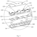
Fig. 3 is a partial enlarged view of a light source module, a reflective cup, a lens component and an anti-glare cup in accordance with a preferred embodiment of the present application. -
Fig. 4 is a schematic stereogram of a reflective cup in accordance with a preferred embodiment of the present application. -
Fig. 5 is a stereogram of the reflective cup in accordance with a preferred embodiment of the present application at another angle. -
Fig. 6 is a schematic stereogram of a lens component in accordance with a preferred embodiment of the present application. -
Fig. 7 is a schematic stereogram of an anti-glare cup in accordance with a preferred embodiment of the present application. -
Fig. 8 is a stereogram of a track linear lamp in accordance with another preferred embodiment of the present application. -
Fig. 9 is an exploded view of a track linear lamp in accordance with another preferred embodiment of the present application. -
Fig. 10 is a schematic stereogram of a lamp holder in accordance with another preferred embodiment of the present application. -
Fig. 11 is a schematic stereogram of a lamp head in accordance with another preferred embodiment of the present application. -
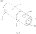
Fig. 12 is a schematic stereogram of a rotating shaft in accordance with another preferred embodiment of the present application. -
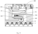
Fig. 13 is a sectional view of a track linear lamp in accordance with another preferred embodiment of the present application. - Descriptions of reference numerals: 100- track linear lamp, 200- linear lamp combination, 300- linear lamp, 400- adapter, 301- lamp body, 302- lamp holder, 303-rotating shaft, 304- cable, 305- lamp head;
- 1- optical assembly, 11- light source module, 111- through hole, 112- light source board, 12- reflective cup, 121- snap-fit slot, 122- support post, 123- connecting member, 124- connecting hole, 125- bump, 126- channel, 127- reflecting cavity, 128- large hole, 129- small hole, 13- lens component, 131- first hook, 132- groove, 133- prism surface, 134- through hole, 14- anti-glare cup, 141- anti-glare cavity, 142- large end, 143- small end, 144- second hook;
- 2- main body part, 3- connecting part, 31- fixing hole, 32- positioning post, 33-locking piece, 4- adapting groove;
- 5- adapting part, 51- fixing hole, 52- rotating hole, 53- position limiting piece, 54-anti-skid piece, 6- connecting groove, 7- rotating part, 71- position limiting groove, 8-fixing part, 81- positioning groove, 82- locking groove, 9- through hole.
- In order to make the purpose, technical scheme and advantages of this application more clear, the application will be described in detail with the attached drawings and specific embodiments.
- Here, it should be noted that in order to avoid obscuring this application with unnecessary details, only the structure and/or processing steps closely related to the scheme of this application are shown in the attached drawings, while other details that are not related to this application are omitted.
- In addition, it should be noted that the terms "including", "include", "comprising", "comprise" or any other variation are intended to cover non-exclusive inclusion, so that a process, a method, an article or an apparatus including a series of elements includes not only those elements, but also other elements not explicitly listed, or elements inherent to such process, method, article or apparatus.
- Referring to
Fig. 1 and Fig. 2 , the present application discloses a tracklinear lamp 100 for mobile lighting. The tracklinear lamp 100 includes a track (not shown) and alinear lamp combination 200, thelinear lamp combination 200 includes anadapter 400 and alinear lamp 300. Specifically, the track is fixedly installed on a wall or ceiling, theadapter 400 is accommodated in the track and can slide along the track, and theadapter 400 and thelinear lamp 300 are fixedly connected, so that theadapter 400 can drive thelinear lamp 300 to slide along the track, thus realizing mobile lighting of thelinear lamp combination 200. Preferably, theadapter 400 and thelinear lamp 300 can be fixedly connected by one or more of screws, rivets, adhesive or buckles. - The
adapter 400 is electrically connected with the track. Thelinear lamp 300 includes acable 304. One end of thecable 304 passes through thelinear lamp 300 and is connected with thelight source module 11 installed in thelinear lamp 300, and the other end of thecable 304 is connected with theadapter 400, so that theadapter 400 can supply power to thelight source module 11. - In this application, the structure of the track in the track
linear lamp 100, the structure of theadapter 400 and the connection mode between theadapter 400 and the track can all be designed according to the prior art, and will not be described in detail here. The specific structure of thelinear lamp 300 will be described in detail below. - Referring to
Fig. 1 and Fig. 2 , in a preferred embodiment of the present application, thelinear lamp 300 includes alamp body 301 and anoptical assembly 1 accommodated in thelamp body 301. Specifically, one side of thelamp body 301 is fixedly connected with anadapter 400, and at least part of thelamp body 301 is accommodated in a track, so that thelamp body 301 can slide along the track under the drive of theadapter 400. Preferably, thelamp body 301 is completely accommodated in the track, so that the direct illumination of thelinear lamp 300 is realized and thelinear lamp 300 is not exposed, and the appearance of thelinear lamp 300 is beautiful. - The side of the
lamp body 301 far away from theadapter 400 is a light outlet (not shown), and the light outlet is recessed inward to form an accommodation space, and theoptical assembly 1 is accommodated in the accommodation space to cover the accommodation space, thus realizing the sealing of thelinear lamp 300. Preferably, thelamp body 301 is arranged in a rectangular shape, and theoptical assembly 1 is embedded in thelamp body 301. - The
optical assembly 1 includes alight source module 11, areflective cup 12, alens component 13, and ananti-glare cup 14 which are sequentially arranged in a height direction. Specifically, thelight source module 11 is installed in thelamp body 301, and thereflective cup 12 is fixedly connected with thelight source module 11, and theanti-glare cup 14 is fixedly connected with thereflective cup 12, and thelens component 13 is fixed between thereflective cup 12 and theanti-glare cup 14, so that light emitted from thelight source module 11 can pass through thereflective cup 12, thelens component 13, and theanti-glare cup 14 in turn and emits outwards from the light outlet. - In this embodiment, two
optical assemblies 1 are arranged in thelamp body 301. Of course, in other embodiments, only oneoptical assembly 1 or a plurality ofoptical assemblies 1 can be arranged in thelamp body 301, and the plurality ofoptical assemblies 1 are respectively connected with thelight source module 11 to cover the accommodation space in thelamp body 301. - Referring to
Fig. 3 to Fig. 7 , thelight source module 11 includes alight source board 112 and a plurality of lamp beads (not shown) fixed on thelight source board 112. Thereflective cup 12 is provided with a plurality of reflectingcavities 127 corresponding to the lamp beads, thelens component 13 is formed with a plurality of prism surfaces 133 corresponding to the reflectingcavities 127, and theanti-glare cup 14 is provided with a plurality ofanti-glare cavities 141 corresponding to the reflectingcavities 127, so that the light emitted from the lamp beads can be first reflected by the reflectingcavities 127, then passes through theprism surface 133, and finally passes through theanti-glare cup 14 and emits outwards from the light outlet. - The whole
reflective cup 12 is surface treated by electroplating process to enhance the reflection effect of light and improve the light efficiency of thelinear lamp 300. Both ends of the reflectingcavity 127 are respectively provided with alarge hole 128 and asmall hole 129, thesmall hole 129 is arranged at one end close to the lamp bead, and thelarge hole 128 is arranged at one end far away from the lamp bead. Thesmall hole 129 is matched with the lamp bead, and the lamp bead can be accommodated in thesmall hole 129, so that the light emitted from the lamp bead can be emitted through the reflection of the reflectingcavity 127. Of course, in other embodiments, the lamp bead may not be completely accommodated in thesmall hole 129. - The inner side wall of the reflecting
cavity 127 is arranged in a fish-scale shape. Because the light emitted from the lamp bead is divergent, the light will change from divergent light to linear light beam after passing through the fish-scale reflecting cavity 127, and it will be emitted outward through thelarge hole 128, so that thereflective cup 12 can control the emission path of the light and reduce the loss of the light in the transmission process. - The size and shape of the
prism surface 133 are matched with the size and shape of thelarge hole 128, respectively, so that the light directly enters theprism surface 133 after passing through thelarge hole 128. Theprism surface 133 is provided with an optical microstructure, specifically a polygonal prism, which makes the light more uniform after passing through theprism surface 133 and achieves the effect of light mixing. - The
anti-glare cavity 141 includes alarge end 142 and asmall end 143, and thesmall end 143 corresponds to theprism surface 133, so that light passing through theprism surface 133 enters thesmall end 143 and then exits from thelarge end 142. The distance between thelarge end 142 and theprism surface 133 is much larger than that between thesmall end 143 and theprism surface 133. In the vertical direction, when the user sees the lamp bead, the angle between the user and the lamp bead becomes smaller, that is, the user can only see the lamp bead when standing under the lamp bead in a certain range, which improves the anti-glare effect of theoptical assembly 1 and enables the user to obtain a better use experience. - The edge of the
reflective cup 12 is provided with snap-fit slots 121, and the edge of thelens component 13 is recessed inward to formgrooves 132, and thegrooves 132 correspond to at least part of the snap-fit slots 121. The edge of thelens component 13 is further provided withfirst hooks 131 in a protruding manner, thefirst hooks 131 and thegrooves 132 are spaced apart from each other, and thefirst hooks 131 can be inserted into the corresponding snap-fit slots 121 to realize the snap-fit connection between thelens component 13 and thereflective cup 12. - The edge of the
anti-glare cup 14 is provided withsecond hooks 144 in a protruding manner, and thesecond hooks 144 and thefirst hooks 131 extend in the same direction. The second hooks 144 correspond to thegrooves 132, so that thesecond hooks 144 can pass through thegrooves 132 and be inserted into the corresponding snap-fit slots 121 to realize the snap-fit connection between theanti-glare cup 14 and thereflective cup 12. Specifically, the snap-fit slots 121, thegrooves 132, thefirst hooks 131, and thesecond hooks 144 are all arranged in pairs. The number of the snap-fit slots 121 is the sum of the number of thefirst hooks 131 and the number of thesecond hooks 144, and the number of thegrooves 132 is the same as that of the second hooks 144. Preferably, there are twelve snap-fit slots 121, eightgrooves 132, fourfirst hooks 131, and eightsecond hooks 144. - The
optical assembly 1 further includes a fixing piece (not shown), and thereflective cup 12 is provided with a connectingmember 123 and a connectinghole 124 formed in the connectingmember 123. Specifically, the connectingmember 123 extends from thereflective cup 12 toward thelight source board 112, and the connectinghole 124 is formed at one end of the connectingmember 123 close to thelight source board 112 and penetrates the connectingmember 123, so that the fixing piece can pass through the connectinghole 124 and be connected with thelight source board 112, thereby fixedly connecting thereflective cup 12 and thelight source module 11. Preferably, there are four connectingmembers 123 which are evenly distributed on the two long-side edges of thereflective cup 12. One side of the connectingmember 123 flush with the long-side edges of thereflective cup 12 is recessed inward to form achannel 126 through which the fixing piece can pass, and the connectinghole 124 is communicated with thechannel 126, so that the fixing piece can pass through thechannel 126 and the connectinghole 124 to realize the fixed connection between thereflective cup 12 and thelight source board 112. Preferably, the fixing piece is a screw, and thelight source board 112 is correspondingly provided with a screw hole. - In this embodiment, the long-side edge of the
lens component 13 is recessed inward to form a throughhole 134, and the throughhole 134 is arranged corresponding to the connectinghole 124, so that the fixing piece can pass through the throughhole 134 and the connectinghole 124 to fixedly connect thereflective cup 12 and thelight source board 112. In this way, thelens component 13 can be connected with thereflective cup 12 in a snap-fit manner, and then thereflective cup 12 and thelight source board 112 can be fixedly connected. Of course, in other embodiments, thelens component 13 may not be provided with the throughhole 134, and thereflective cup 12 is fixedly connected with thelight source board 112 first, and then thelens component 13 is connected with thereflective cup 12 in a snap-fit manner. - One end of the connecting
member 123 far away from thereflective cup 12 is further provided with abump 125, and thelight source board 112 is correspondingly provided with a throughhole 111 matched with thebump 125. When thereflective cup 12 is connected with thelight source board 112, thebump 125 can be accommodated in the throughhole 111, so as to realize the positioning between thereflective cup 12 and thelight source board 112, reduce the installation error between thereflective cup 12 and thelight source board 112, and avoid the optical abnormality of theoptical assembly 1. In this embodiment, only two connectingmembers 123 near the short-side edges of thereflective cup 12 are provided with thebumps 125, so as to realize the positioning between thereflective cup 12 and thelight source board 112. Of course, all the connectingmembers 123 may be provided with thebumps 125 to further enhance the positioning accuracy between thereflective cup 12 and thelight source board 112, and there is no limitation herein. - The
reflective cup 12 is further provided with asupport post 122 which is arranged on the same side of thereflective cup 12 with the connectingmember 123 and protrudes toward thelight source board 112. The end of thesupport post 122 close to thelight source board 112 is flush with the end of the connectingmember 123 close to thelight source board 112, so that when thereflective cup 12 is connected with thelight source board 112, thesupport post 122 and the connectingmember 123 can be used to abut against thelight source board 112, so as to keep a certain distance between thereflective cup 12 and thelight source board 112, and to avoid the lamp bead from being damaged due to the contact between the reflectingcavity 127 and the lamp bead. Preferably, there are sixsupport posts 122 which are evenly distributed on the two long-side edges of thereflective cup 12. In this embodiment, there are two types ofsupport posts 122 which are L-shaped and T-shaped, respectively. Four L-shaped support posts 122 are located at the four corners of thereflective cup 12, and two T-shaped support posts 122 are located at the middle of the two long sides of thereflective cup 12. Of course, in other embodiments, the shape and number ofsupport posts 122 can be set according to the actual situation, and there is no limitation herein. - Please refer to
Fig. 8 andFig. 9 , in another preferred embodiment of the application, thelamp body 301 includes alamp holder 302, alamp head 305 and arotating shaft 303 connecting thelamp holder 302 and thelamp head 305. Therotating shaft 303 is arranged at the joint of thelamp holder 302 and thelamp head 305, so that thelamp head 305 can rotate relative to thelamp holder 302, thereby realizing illumination at different angles, and improving the practicability of thelinear lamp 300. The side of thelamp holder 302 far away from thelamp head 305 is fixedly connected with theadapter 400, and at least part of thelamp holder 302 is accommodated in the track, so that on the one hand, thelinear lamp 300 can slide along the track when being driven by theadapter 400, on the other hand, the exposure of thelamp holder 302 is reduced to improve the aesthetics of the tracklinear lamp 100, and moreover, thelamp head 305 can be prevented from abutting against the track after rotating. - The
lamp head 305 includes amain body part 2, a connectingpart 3 extending outward from themain body part 2, and an adaptinggroove 4 surrounded and delimited by the connectingpart 3 and themain body part 2. That is to say, the top of thelamp head 305 is divided into two parts, one part protrudes upward to form the connectingpart 3, and the other part is recessed downward to form the adaptinggroove 4. The overall configuration of thelamp head 305 is generally L-shaped. Specifically, theoptical assembly 1 is accommodated in themain body part 2, and the structure of theoptical assembly 1 is the same as that of theoptical assembly 1 mentioned above, so it will not be described in detail herein. The following will mainly describe the specific structure and matching relationship of thelamp head 305, thelamp holder 302 and therotating shaft 303. - Please refer to
Fig. 9 to Fig. 11 , the end of thelamp holder 302 far away from theadapter 400 is provided with an adaptingpart 5 and a connectinggroove 6 located beside the adaptingpart 5. Specifically, the adaptingpart 5 is formed by extending outward from the end of thelamp holder 302 far away from theadapter 400, and the connectinggroove 6 is formed by being surrounded and delimited by the adaptingpart 5 and thelamp holder 302. That is to say, the bottom of thelamp holder 302 is divided into two parts, one part of which protrudes downward to form the adaptingpart 5 and the other part of which is recessed upward to form a connectinggroove 6. The overall configuration of thelamp holder 302 is generally L-shaped. The connectingpart 3 and the connectinggroove 6 correspond to each other and the connectingpart 3 can be accommodated in the connectinggroove 6, and the adaptingpart 5 and the adaptinggroove 4 correspond to each other and the adaptingpart 5 can be accommodated in the adaptinggroove 4 to realize the embedded connection between thelamp holder 302 and thelamp head 305. Therotating shaft 303 is arranged between the connectingpart 3 and the adaptingpart 5 and partially extends into the connectingpart 3 and the adaptingpart 5, so that the connectingpart 3 is rotatably connected with the adaptingpart 5 through therotating shaft 303. - Please refer to
Fig. 9 to Fig. 13 , therotating shaft 303 is arranged in a cylindrical shape, with one end being therotating part 7 and the other end being the fixingpart 8. The adaptingpart 5 is provided with arotating hole 52 extending along the long side of thelamp holder 302, and therotating part 7 is accommodated in therotating hole 52 to realize the connection between therotating shaft 303 and thelamp holder 302. The connectingpart 3 is provided with a fixinghole 31 extending along the long side of thelamp head 305, and the fixingpart 8 is accommodated in the fixinghole 31 to realize the connection between therotating shaft 303 and thelamp head 305. - The
rotating part 7 is provided with aposition limiting groove 71, and aposition limiting piece 53 is arranged in the adaptingpart 5, and the position and the shape of theposition limiting piece 53 are matched with the position and the shape of theposition limiting groove 71, respectively. Specifically, theposition limiting groove 71 is arranged in the outer side wall of therotating part 7 in a strip shape, and theposition limiting piece 53 extends into the rotatinghole 52 from the adaptingpart 5, and theposition limiting piece 53 at least partially extends into theposition limiting groove 71 and can slide in theposition limiting groove 71, so that therotating shaft 303 can rotate relative to the adaptingpart 5. When therotating shaft 303 rotates at a certain angle with respect to the adaptingpart 5, the adaptingpart 53 is configured to abut against the inner side wall of one end of theposition limiting groove 71, so as to limit the sliding distance of the adaptingpart 53 in theposition limiting groove 71, and further limit the rotation angle of therotating shaft 303 with respect to the adaptingpart 5. - The adapting
part 5 is further provided with anabutting post 51, specifically, the abuttingpost 51 is arranged in therotating hole 52, and the end of therotating part 7 far away from the fixingpart 8 can abut against the abuttingpost 51 to limit the length of therotating shaft 303 extending into the rotatinghole 52, so that therotating part 7 can rub against the abuttingpost 51 during the rotating process of therotating shaft 303, on the one hand, therotating shaft 303 can be fixed at a specific angle by the friction between therotating part 7 and theabutting post 51. - An
anti-skid piece 54 is further arranged in the adaptingpart 5, theanti-skid piece 54 extends from the top of the adaptingpart 5 toward the inside of therotating hole 52, so that one end of theanti-skid piece 54 abuts against the outer side wall of therotating shaft 303 and the other end of theanti-skid piece 54 is accommodated in the adaptingpart 5. Friction can be generated upon theanti-skid part 54 abutting against the outer wall of therotating shaft 303, so that therotating shaft 303 and theanti-skid part 54 can remain relatively stationary or can relatively slide, that is, therotating shaft 303 can be fixed at a specific angle by using theanti-skid part 54 without an external force. Under the action of an external force, therotating shaft 303 can slide relative to theanti-skid piece 54. - Preferably, the
anti-skid piece 54 is a dampingscrew 54. In this embodiment, there are two dampingscrews 54, both of which are arranged in the adaptingpart 5 to enhance the anti-skid performance. Of course, in other embodiments, the number of the dampingscrews 54 can be set to one or more, and the dampingscrews 54 can also be arranged in the connectinggroove 6, that is, they extend into the connectinggroove 6 from the inside of thelamp holder 302, so that one end of each of the damping screws 54 abuts against the connectingpart 3 to realize the anti-skid effect of the dampingscrew 54. - The fixing
part 8 is provided with a lockinggroove 82 and apositioning groove 81. Specifically, the lockinggroove 82 is a notch arranged on the outer side wall of the fixingpart 8, and thepositioning groove 81 is arranged at one end of the fixingpart 8 far away from therotating part 7, and is recessed inward from the edge of the fixingpart 8. Apositioning post 32 corresponding to thepositioning groove 81 and alocking piece 33 corresponding to the lockinggroove 82 are arranged in the connectingpart 3. Specifically, both thepositioning post 32 and thelocking piece 33 extend from the connectingpart 3 toward the fixinghole 31, and thepositioning post 32 and thelocking piece 33 are oppositely arranged in the fixinghole 31. During connection, thepositioning post 32 extends into thepositioning groove 81, and thelocking piece 33 abuts against the lockinggroove 82 to fix the fixingpart 8 in the fixinghole 31, so that the connectingpart 3 is fixedly connected with therotating shaft 303 and can rotate synchronously with therotating shaft 303. - That is to say, after the
lamp head 305 and thelamp holder 302 are connected through therotating shaft 303, the fixingpart 8 is accommodated in the fixinghole 31, and the fixingpart 8 and thelamp head 305 are fixedly connected through the cooperation of thepositioning post 32 and thelocking piece 33 with thepositioning groove 81 and the lockinggroove 82, respectively. Therotating part 7 is accommodated in therotating hole 52, and therotating part 7 can rotate within a certain angle range relative to thelamp holder 302 through the mutual cooperation of theposition limiting piece 53 and theposition limiting groove 71, and therotating shaft 303 can be fixed at a specific angle through the dampingscrew 54 without an external force. Meanwhile, through the mutual cooperation between the positioningpost 32 and theabutting post 51, therotating shaft 303 can be limited between the connectingpart 3 and the adaptingpart 5, so as to avoid therotating shaft 303 from being displaced during use. Preferably, both theposition limiting piece 53 and thelocking piece 33 are screws. - The
rotating shaft 303 is also provided with a throughhole 9 which runs through therotating part 7 and the fixingpart 8 along the rotating axis of therotating shaft 303. Thelinear lamp 300 further includes acable 304. One end of thecable 304 passes through thelamp holder 302 and is connected with theadapter 400, while the other end of thecable 304 passes through the throughhole 9 and enters thelamp head 305 and is electrically connected with theoptical assembly 1 in thelamp head 305 to supply power to theoptical assembly 1. - To sum up, in the track
linear lamp 100 of the present application, thereflective cup 12 of theoptical assembly 1 is provided with snap-fit slots 121, thelens component 13 is provided with thefirst hooks 131 and thegrooves 132 that correspond to the snap-fit slots 121, and theanti-glare cup 14 is provided with thesecond hooks 144, so that thelens component 13 and theanti-glare cup 14 can be fixed with thereflective cup 12 in a snap-fit manner, and the accurate installation of thelens component 13 and convenient assembly of theoptical assembly 1 are realized. By arranging thesupport post 122 on thereflective cup 12, it can be avoided that the reflectingcavity 127 abuts against the lamp bead, resulting in the lamp bead being damaged. By arranging the throughholes 134 in thelens component 13, the diversity of the assembly of theoptical assembly 1 is realized. By arranging therotating shaft 303 between thelamp holder 302 and thelamp head 305, thelamp head 305 can rotate relative to thelamp holder 302 to meet the lighting requirements of objects with different heights. Thepositioning post 32 and theabutting post 51 are used to limit the position of therotating shaft 303 in the connectingpart 3 and the adaptingpart 5, so as to prevent therotating shaft 303 from being displaced during use. By arranging theanti-skid piece 54 abutting against therotating shaft 303 on thelamp holder 302, it is realized that therotating shaft 303 can remain stationary relative to the adaptingpart 5, which can not only meet the different needs of customers, but also meet the needs of different lighting scenes. - The above embodiments are only used to illustrate the technical scheme of the application, but not used to limit the application. Although the application has been described in detail with reference to the preferred embodiments, ordinary people in the field should understand that the technical scheme of the application can be modified or replaced by equivalents without departing from the spirit and scope of the technical scheme of the application.
Claims (15)
- An optical assembly, comprising a light source module (11), a reflective cup (12), a lens component (13), and an anti-glare cup (14) which are sequentially arranged in a height direction, wherein an edge of the reflective cup (12) is provided with a snap-fit slot (121), and an edge of the lens component (13) is provided with a first hook (131) in a protruding manner, the anti-glare cup (14) is provided with a second hook (144) in a protruding manner, the first hook (131) and the second hook (144) extend in a same direction so as to be inserted into a corresponding snap-fit slot (121), and the reflective cup (12), the lens component (13), and the anti-glare cup (14) are connected in a snap-fit manner.
- The optical assembly according to claim 1, wherein the edge of the lens component (13) is recessed inward to form a groove (132), and the groove (132) and the snap-fit slot (121) at least partially correspond to each other, so that the second hook (144) passes through the groove (132) and is inserted into the corresponding snap-fit slot (121).
- The optical assembly according to claim 1, wherein the light source module (11) comprises a light source board (112) and lamp beads fixed on the light source board (112), the reflective cup (12) is provided with a reflecting cavity (127) corresponding to the lamp beads, and the lens component (13) is formed with a prism surface (133) corresponding to the reflecting cavity (127), the anti-glare cup (14) is provided with an anti-glare cavity (141) corresponding to the reflecting cavity (127), and light emitted from the lamp beads passes through the reflecting cavity (127), the prism surface (133), and the anti-glare cavity (141) in turn and is emitted outwards.
- The optical assembly according to claim 3, wherein the reflective cup (12) is provided with a connecting member (123) and a connecting hole (124) in the connecting member (123), and the optical assembly (1) further comprises a fixing piece which passes through the connecting hole (124) and is connected with the light source board (112).
- The optical assembly according to claim 4, wherein the connecting member (123) is provided with a bump (125), the light source board (112) is provided with a through hole (111) matched with the bump (125), and the bump (125) is accommodated in the through hole (111).
- The optical assembly according to claim 4, wherein the reflective cup (12) is further provided with a support post (122), and the support post (122) and the connecting member (123) are arranged on a same side of the reflective cup (12) and protrude toward the light source board (112) so as to abut against the light source board (112) respectively.
- A linear lamp, comprising a lamp body (301) and an optical assembly (1) accommodated in the lamp body (301), wherein the optical assembly (1) comprises a light source module (11), a reflective cup (12), a lens component (13), and an anti-glare cup (14) which are sequentially arranged in a height direction, an edge of the reflective cup (12) is provided with a snap-fit slot (121), and an edge of the lens component (13) is provided with a first hook (131) in a protruding manner, the anti-glare cup (14) is provided with a second hook (144) in a protruding manner, the first hook (131) and the second hook (144) extend in a same direction so as to be inserted into the corresponding snap-fit slot (121), and the reflective cup (12), the lens component (13), and the anti-glare cup (14) are connected in a snap-fit manner.
- The linear lamp according to claim 7, wherein the lamp body (301) comprises a lamp holder (302), a lamp head (305) and a rotating shaft (303), the optical assembly (1) is accommodated in the lamp head (305), and the rotating shaft (303) is arranged at a joint of the lamp holder (302) and the lamp head (305), so that the lamp head (305) is rotatable relative to the lamp holder (302).
- The linear lamp according to claim 8, wherein the lamp head (305) comprises a main body part (2) and a connecting part (3) protruding outward from the main body part (2), and the lamp holder (302) is provided with an adapting part (5) and a connecting groove (6) located beside the adapting part (5), the connecting part (3) is accommodated in the connecting groove (6), and the connecting part (3) is rotatably connected with the adapting part (5) through the rotating shaft (303).
- The linear lamp according to claim 9, wherein the rotating shaft (303) comprises a rotating part (7) and a position limiting groove (71) in the rotating part (7), a position limiting piece (53) is arranged in the adapting part (5), and the position limiting piece (53) partially extends into the position limiting groove (71), and is capable of sliding in the position limiting groove (71), and the position limiting piece (53) is configured to abut against an inner side wall of the position limiting groove (71) to limit a rotation angle of the rotating shaft (303).
- The linear lamp according to claim 9, wherein the adapting part (5) further comprises an anti-skid piece (54), and one end of the anti-skid piece (54) abuts against an outer side wall of the rotating shaft (303), so that the rotating shaft (303) is capable of keeping stationary relative to the anti-skid piece (54) or is capable of sliding relative to the anti-skid piece (54).
- The linear lamp according to claim 9, wherein the rotating shaft (303) comprises a fixing part (8), and a locking groove (82) and a positioning groove (81) formed in the fixing part (8), the connecting part (3) is provided with a positioning post (32) and a locking piece (33), the positioning post (32) is accommodated in the positioning groove (81), and the locking piece (33) abuts against the locking groove (82), so that the connecting part (3) is fixedly connected with the rotating shaft (303) and is rotatable synchronously with the rotating shaft (303).
- A linear lamp combination, comprising an adapter (400) and a linear lamp (300) fixedly connected with the adapter (400), wherein the linear lamp (300) comprises a lamp body (301) and an optical assembly (1) accommodated in the lamp body (301), the optical assembly comprises a light source module (11), a reflective cup (12), a lens component (13), and an anti-glare cup (14) which are sequentially arranged in a height direction, an edge of the reflective cup (12) is provided with a snap-fit slot (121), and an edge of the lens component (13) is provided with a first hook (131) in a protruding manner, the anti-glare cup (14) is provided with a second hook (144) in a protruding manner, the first hook (131) and the second hook (144) extend in a same direction so as to be inserted into a corresponding snap-fit slot (121), and the reflective cup (12), the lens component (13), and the anti-glare cup (14) are connected in a snap-fit manner.
- The linear lamp combination according to claim 13, wherein the lamp body (301) comprises a rotating shaft (303), a lamp head (305) and a lamp holder (302), the optical assembly (1) is accommodated in the lamp head (305), and the lamp head (305) is rotatably connected with the lamp holder (302) through the rotating shaft (303), the adapter (400) is fixedly connected with the lamp holder (302).
- A track linear lamp, comprising a track and a linear lamp combination (200), wherein the adapter (400) is accommodated in the track and the linear lamp (300) is at least partially accommodated in the track, and the linear lamp combination (200) comprises an adapter (400) and a linear lamp (300) fixedly connected with the adapter (400), the linear lamp (300) comprises a lamp body (301) and an optical assembly (1) accommodated in the lamp body (301), the optical assembly comprises a light source module (11), a reflective cup (12), a lens component (13), and an anti-glare cup (14) which are sequentially arranged in a height direction, an edge of the reflective cup (12) is provided with a snap-fit slot (121), and an edge of the lens component (13) is provided with a first hook (131) in a protruding manner, the anti-glare cup (14) is provided with a second hook (144) in a protruding manner, the first hook (131) and the second hook (144) extend in a same direction so as to be inserted into a corresponding snap-fit slot (121), and the reflective cup (12), the lens component (13), and the anti-glare cup (14) are connected in a snap-fit manner.
Applications Claiming Priority (2)
| Application Number | Priority Date | Filing Date | Title |
|---|---|---|---|
| CN202221236590.4U CN217235506U (en) | 2022-05-23 | 2022-05-23 | Optical assembly, linear lamp combination and track linear lamp |
| PCT/CN2023/084740 WO2023226585A1 (en) | 2022-05-23 | 2023-03-29 | Optical assembly, linear lamp, linear lamp combination, and track linear lamp |
Publications (2)
| Publication Number | Publication Date |
|---|---|
| EP4530527A1 true EP4530527A1 (en) | 2025-04-02 |
| EP4530527A4 EP4530527A4 (en) | 2025-09-24 |
Family
ID=82824160
Family Applications (1)
| Application Number | Title | Priority Date | Filing Date |
|---|---|---|---|
| EP23810660.3A Pending EP4530527A4 (en) | 2022-05-23 | 2023-03-29 | OPTICAL ARRANGEMENT, LINEAR LAMP, LINEAR LAMP COMBINATION AND TRACK LINEAR LAMP |
Country Status (4)
| Country | Link |
|---|---|
| US (1) | US12607326B2 (en) |
| EP (1) | EP4530527A4 (en) |
| CN (1) | CN217235506U (en) |
| WO (1) | WO2023226585A1 (en) |
Families Citing this family (1)
| Publication number | Priority date | Publication date | Assignee | Title |
|---|---|---|---|---|
| CN217235506U (en) * | 2022-05-23 | 2022-08-19 | 欧普照明股份有限公司 | Optical assembly, linear lamp combination and track linear lamp |
Family Cites Families (17)
| Publication number | Priority date | Publication date | Assignee | Title |
|---|---|---|---|---|
| CN202236590U (en) | 2011-09-05 | 2012-05-30 | 成都市新津事丰医疗器械有限公司 | Novel photophobic burette type infusion apparatus |
| CN203642109U (en) * | 2013-07-22 | 2014-06-11 | 南京迈瑞生物医疗电子有限公司 | Surgical lamp component |
| CN205842520U (en) * | 2016-06-30 | 2016-12-28 | 中山市格锐智造光学有限公司 | An anti-glare LED lamp |
| DE102018102400A1 (en) * | 2017-02-24 | 2018-08-30 | Panasonic Intellectual Property Management Co., Ltd. | lighting device |
| CN110131597A (en) * | 2018-02-08 | 2019-08-16 | 佛山市赛明照明电器有限公司 | A kind of LED worklight of automatic heating Anti-ice-and-snow |
| CN210107174U (en) * | 2019-07-18 | 2020-02-21 | 广东阿路兹照明实业有限公司 | Guide rail lamp |
| CN211372036U (en) * | 2019-11-20 | 2020-08-28 | 陈带球 | Novel vertical guide rail lamp structure |
| CN210831841U (en) * | 2019-12-03 | 2020-06-23 | 中山科益光学有限公司 | Reflective cup module and line lamp |
| CN212901339U (en) * | 2020-05-26 | 2021-04-06 | 中山市格锐智造光学有限公司 | Optical structure |
| CN212005342U (en) * | 2020-05-29 | 2020-11-24 | 深圳市越宏普照照明科技有限公司 | Track lighting lamp |
| CN212537567U (en) * | 2020-06-08 | 2021-02-12 | 中山科益光学有限公司 | An LED light optical component |
| CN212252439U (en) * | 2020-06-30 | 2020-12-29 | 中山市三强照明科技有限公司 | Optical module and magnetic adsorption LED track light |
| ES3066108T3 (en) * | 2020-08-18 | 2026-05-11 | Self Electronics Co Ltd | Anti-glare lamp and lighting arrangement method using the lamp |
| CN212777033U (en) * | 2020-10-09 | 2021-03-23 | 江门市企一照明有限公司 | Illumination angle adjustable is light for track |
| DE102021106644B4 (en) * | 2021-03-18 | 2023-11-16 | Bjb Gmbh & Co. Kg | Cover for a lamp and lamp with cover |
| CN113028363A (en) * | 2021-03-24 | 2021-06-25 | 深圳市旺坤光电技术有限公司 | LED court lamp anti-dazzle optical system |
| CN217235506U (en) * | 2022-05-23 | 2022-08-19 | 欧普照明股份有限公司 | Optical assembly, linear lamp combination and track linear lamp |
-
2022
- 2022-05-23 CN CN202221236590.4U patent/CN217235506U/en active Active
-
2023
- 2023-03-29 EP EP23810660.3A patent/EP4530527A4/en active Pending
- 2023-03-29 WO PCT/CN2023/084740 patent/WO2023226585A1/en not_active Ceased
-
2024
- 2024-11-22 US US18/956,364 patent/US12607326B2/en active Active
Also Published As
| Publication number | Publication date |
|---|---|
| WO2023226585A1 (en) | 2023-11-30 |
| EP4530527A4 (en) | 2025-09-24 |
| US20250084982A1 (en) | 2025-03-13 |
| US12607326B2 (en) | 2026-04-21 |
| CN217235506U (en) | 2022-08-19 |
Similar Documents
| Publication | Publication Date | Title |
|---|---|---|
| US9410680B2 (en) | Illumination devices with adjustable optical elements | |
| EP3027963B1 (en) | Reflector for directed beam led illumination | |
| EP4031805B1 (en) | Lighting lamp | |
| US12607326B2 (en) | Optical assembly, linear lamp, linear lamp combination, and track linear lamp | |
| US10539737B2 (en) | Lighting fixture with end plate slots and elongated heat sinks for retaining an edge-lit optical device | |
| WO2019129040A1 (en) | Annular light distribution element, light source module, light source component and lighting lamp | |
| WO2019114591A1 (en) | Illumination device and light source module | |
| US9719662B1 (en) | Thin-form lens for volume lighting applications | |
| CN211853635U (en) | Goods shelves lamp and signboard lamp | |
| US10976036B2 (en) | Rotatable linear downlight | |
| CN112483961A (en) | Lighting lamp | |
| WO2024051640A1 (en) | Focusing spotlight | |
| CN215001255U (en) | Projection lamp | |
| CN210687896U (en) | Light distribution components and lighting fixtures | |
| CN220379524U (en) | Light source substrate connection structure of projection lamp and projection lamp manufactured by same | |
| CN223425133U (en) | Wire track lamp | |
| CN220436329U (en) | Laser lighting device | |
| CN114321783A (en) | Lamp shell assembly and lamp applying same | |
| KR102182715B1 (en) | Plate type led illuminator | |
| CN219102855U (en) | Angle-adjustable shelf lamp and shelf lighting system | |
| CN219177507U (en) | Non-direct lighting lamp with offset light-emitting unit | |
| JP2002335377A (en) | Linear lighting device | |
| US20250129916A1 (en) | A trunk fixture for a trunking illumination system for line illumination, as well as a trunking illumination system composed of one or more of such trunk fixtures | |
| CN215489368U (en) | A sloping roof downlight | |
| CN210624262U (en) | a spotlight |
Legal Events
| Date | Code | Title | Description |
|---|---|---|---|
| STAA | Information on the status of an ep patent application or granted ep patent |
Free format text: STATUS: THE INTERNATIONAL PUBLICATION HAS BEEN MADE |
|
| PUAI | Public reference made under article 153(3) epc to a published international application that has entered the european phase |
Free format text: ORIGINAL CODE: 0009012 |
|
| STAA | Information on the status of an ep patent application or granted ep patent |
Free format text: STATUS: REQUEST FOR EXAMINATION WAS MADE |
|
| 17P | Request for examination filed |
Effective date: 20241223 |
|
| AK | Designated contracting states |
Kind code of ref document: A1 Designated state(s): AL AT BE BG CH CY CZ DE DK EE ES FI FR GB GR HR HU IE IS IT LI LT LU LV MC ME MK MT NL NO PL PT RO RS SE SI SK SM TR |
|
| DAV | Request for validation of the european patent (deleted) | ||
| DAX | Request for extension of the european patent (deleted) | ||
| A4 | Supplementary search report drawn up and despatched |
Effective date: 20250822 |
|
| RIC1 | Information provided on ipc code assigned before grant |
Ipc: F21V 21/34 20060101AFI20250818BHEP Ipc: F21V 21/30 20060101ALI20250818BHEP Ipc: F21S 8/00 20060101ALI20250818BHEP Ipc: F21V 17/02 20060101ALI20250818BHEP Ipc: F21V 17/16 20060101ALI20250818BHEP |