EP4530518A2 - Fluidkomponentenkörper und verfahren zu seiner herstellung - Google Patents
Fluidkomponentenkörper und verfahren zu seiner herstellung Download PDFInfo
- Publication number
- EP4530518A2 EP4530518A2 EP25157586.6A EP25157586A EP4530518A2 EP 4530518 A2 EP4530518 A2 EP 4530518A2 EP 25157586 A EP25157586 A EP 25157586A EP 4530518 A2 EP4530518 A2 EP 4530518A2
- Authority
- EP
- European Patent Office
- Prior art keywords
- conduit
- bending
- flow path
- cross
- portions
- Prior art date
- Legal status (The legal status is an assumption and is not a legal conclusion. Google has not performed a legal analysis and makes no representation as to the accuracy of the status listed.)
- Pending
Links
Images


Classifications
-
- F—MECHANICAL ENGINEERING; LIGHTING; HEATING; WEAPONS; BLASTING
- F16—ENGINEERING ELEMENTS AND UNITS; GENERAL MEASURES FOR PRODUCING AND MAINTAINING EFFECTIVE FUNCTIONING OF MACHINES OR INSTALLATIONS; THERMAL INSULATION IN GENERAL
- F16K—VALVES; TAPS; COCKS; ACTUATING-FLOATS; DEVICES FOR VENTING OR AERATING
- F16K27/00—Construction of housing; Use of materials therefor
- F16K27/003—Housing formed from a plurality of the same valve elements
-
- B—PERFORMING OPERATIONS; TRANSPORTING
- B22—CASTING; POWDER METALLURGY
- B22F—WORKING METALLIC POWDER; MANUFACTURE OF ARTICLES FROM METALLIC POWDER; MAKING METALLIC POWDER; APPARATUS OR DEVICES SPECIALLY ADAPTED FOR METALLIC POWDER
- B22F5/00—Manufacture of workpieces or articles from metallic powder characterised by the special shape of the product
- B22F5/10—Manufacture of workpieces or articles from metallic powder characterised by the special shape of the product of articles with cavities or holes, not otherwise provided for in the preceding subgroups
- B22F5/106—Tube or ring forms
-
- B—PERFORMING OPERATIONS; TRANSPORTING
- B21—MECHANICAL METAL-WORKING WITHOUT ESSENTIALLY REMOVING MATERIAL; PUNCHING METAL
- B21D—WORKING OR PROCESSING OF SHEET METAL OR METAL TUBES, RODS OR PROFILES WITHOUT ESSENTIALLY REMOVING MATERIAL; PUNCHING METAL
- B21D7/00—Bending rods, profiles, or tubes
-
- B—PERFORMING OPERATIONS; TRANSPORTING
- B33—ADDITIVE MANUFACTURING TECHNOLOGY
- B33Y—ADDITIVE MANUFACTURING, i.e. MANUFACTURING OF THREE-DIMENSIONAL [3-D] OBJECTS BY ADDITIVE DEPOSITION, ADDITIVE AGGLOMERATION OR ADDITIVE LAYERING, e.g. BY 3-D PRINTING, STEREOLITHOGRAPHY OR SELECTIVE LASER SINTERING
- B33Y10/00—Processes of additive manufacturing
-
- B—PERFORMING OPERATIONS; TRANSPORTING
- B33—ADDITIVE MANUFACTURING TECHNOLOGY
- B33Y—ADDITIVE MANUFACTURING, i.e. MANUFACTURING OF THREE-DIMENSIONAL [3-D] OBJECTS BY ADDITIVE DEPOSITION, ADDITIVE AGGLOMERATION OR ADDITIVE LAYERING, e.g. BY 3-D PRINTING, STEREOLITHOGRAPHY OR SELECTIVE LASER SINTERING
- B33Y80/00—Products made by additive manufacturing
-
- F—MECHANICAL ENGINEERING; LIGHTING; HEATING; WEAPONS; BLASTING
- F16—ENGINEERING ELEMENTS AND UNITS; GENERAL MEASURES FOR PRODUCING AND MAINTAINING EFFECTIVE FUNCTIONING OF MACHINES OR INSTALLATIONS; THERMAL INSULATION IN GENERAL
- F16K—VALVES; TAPS; COCKS; ACTUATING-FLOATS; DEVICES FOR VENTING OR AERATING
- F16K11/00—Multiple-way valves, e.g. mixing valves; Pipe fittings incorporating such valves
- F16K11/10—Multiple-way valves, e.g. mixing valves; Pipe fittings incorporating such valves with two or more closure members not moving as a unit
-
- F—MECHANICAL ENGINEERING; LIGHTING; HEATING; WEAPONS; BLASTING
- F16—ENGINEERING ELEMENTS AND UNITS; GENERAL MEASURES FOR PRODUCING AND MAINTAINING EFFECTIVE FUNCTIONING OF MACHINES OR INSTALLATIONS; THERMAL INSULATION IN GENERAL
- F16K—VALVES; TAPS; COCKS; ACTUATING-FLOATS; DEVICES FOR VENTING OR AERATING
- F16K27/00—Construction of housing; Use of materials therefor
- F16K27/02—Construction of housing; Use of materials therefor of lift valves
- F16K27/0236—Diaphragm cut-off apparatus
-
- F—MECHANICAL ENGINEERING; LIGHTING; HEATING; WEAPONS; BLASTING
- F16—ENGINEERING ELEMENTS AND UNITS; GENERAL MEASURES FOR PRODUCING AND MAINTAINING EFFECTIVE FUNCTIONING OF MACHINES OR INSTALLATIONS; THERMAL INSULATION IN GENERAL
- F16K—VALVES; TAPS; COCKS; ACTUATING-FLOATS; DEVICES FOR VENTING OR AERATING
- F16K27/00—Construction of housing; Use of materials therefor
- F16K27/02—Construction of housing; Use of materials therefor of lift valves
- F16K27/0263—Construction of housing; Use of materials therefor of lift valves multiple way valves
-
- F—MECHANICAL ENGINEERING; LIGHTING; HEATING; WEAPONS; BLASTING
- F16—ENGINEERING ELEMENTS AND UNITS; GENERAL MEASURES FOR PRODUCING AND MAINTAINING EFFECTIVE FUNCTIONING OF MACHINES OR INSTALLATIONS; THERMAL INSULATION IN GENERAL
- F16L—PIPES; JOINTS OR FITTINGS FOR PIPES; SUPPORTS FOR PIPES, CABLES OR PROTECTIVE TUBING; MEANS FOR THERMAL INSULATION IN GENERAL
- F16L11/00—Hoses, i.e. flexible pipes
- F16L11/04—Hoses, i.e. flexible pipes made of rubber or flexible plastics
- F16L11/12—Hoses, i.e. flexible pipes made of rubber or flexible plastics with arrangements for particular purposes, e.g. specially profiled, with protecting layer, heated, electrically conducting
- F16L11/121—Hoses, i.e. flexible pipes made of rubber or flexible plastics with arrangements for particular purposes, e.g. specially profiled, with protecting layer, heated, electrically conducting specially profiled cross sections
-
- F—MECHANICAL ENGINEERING; LIGHTING; HEATING; WEAPONS; BLASTING
- F16—ENGINEERING ELEMENTS AND UNITS; GENERAL MEASURES FOR PRODUCING AND MAINTAINING EFFECTIVE FUNCTIONING OF MACHINES OR INSTALLATIONS; THERMAL INSULATION IN GENERAL
- F16L—PIPES; JOINTS OR FITTINGS FOR PIPES; SUPPORTS FOR PIPES, CABLES OR PROTECTIVE TUBING; MEANS FOR THERMAL INSULATION IN GENERAL
- F16L11/00—Hoses, i.e. flexible pipes
- F16L11/14—Hoses, i.e. flexible pipes made of rigid material, e.g. metal or hard plastics
- F16L11/15—Hoses, i.e. flexible pipes made of rigid material, e.g. metal or hard plastics corrugated
-
- F—MECHANICAL ENGINEERING; LIGHTING; HEATING; WEAPONS; BLASTING
- F16—ENGINEERING ELEMENTS AND UNITS; GENERAL MEASURES FOR PRODUCING AND MAINTAINING EFFECTIVE FUNCTIONING OF MACHINES OR INSTALLATIONS; THERMAL INSULATION IN GENERAL
- F16L—PIPES; JOINTS OR FITTINGS FOR PIPES; SUPPORTS FOR PIPES, CABLES OR PROTECTIVE TUBING; MEANS FOR THERMAL INSULATION IN GENERAL
- F16L43/00—Bends; Siphons
- F16L43/02—Bends; Siphons adapted to make use of special securing means
-
- B—PERFORMING OPERATIONS; TRANSPORTING
- B22—CASTING; POWDER METALLURGY
- B22F—WORKING METALLIC POWDER; MANUFACTURE OF ARTICLES FROM METALLIC POWDER; MAKING METALLIC POWDER; APPARATUS OR DEVICES SPECIALLY ADAPTED FOR METALLIC POWDER
- B22F10/00—Additive manufacturing of workpieces or articles from metallic powder
- B22F10/20—Direct sintering or melting
-
- B—PERFORMING OPERATIONS; TRANSPORTING
- B22—CASTING; POWDER METALLURGY
- B22F—WORKING METALLIC POWDER; MANUFACTURE OF ARTICLES FROM METALLIC POWDER; MAKING METALLIC POWDER; APPARATUS OR DEVICES SPECIALLY ADAPTED FOR METALLIC POWDER
- B22F10/00—Additive manufacturing of workpieces or articles from metallic powder
- B22F10/40—Structures for supporting workpieces or articles during manufacture and removed afterwards
- B22F10/47—Structures for supporting workpieces or articles during manufacture and removed afterwards characterised by structural features
-
- B—PERFORMING OPERATIONS; TRANSPORTING
- B22—CASTING; POWDER METALLURGY
- B22F—WORKING METALLIC POWDER; MANUFACTURE OF ARTICLES FROM METALLIC POWDER; MAKING METALLIC POWDER; APPARATUS OR DEVICES SPECIALLY ADAPTED FOR METALLIC POWDER
- B22F10/00—Additive manufacturing of workpieces or articles from metallic powder
- B22F10/60—Treatment of workpieces or articles after build-up
- B22F10/66—Treatment of workpieces or articles after build-up by mechanical means
-
- B—PERFORMING OPERATIONS; TRANSPORTING
- B22—CASTING; POWDER METALLURGY
- B22F—WORKING METALLIC POWDER; MANUFACTURE OF ARTICLES FROM METALLIC POWDER; MAKING METALLIC POWDER; APPARATUS OR DEVICES SPECIALLY ADAPTED FOR METALLIC POWDER
- B22F5/00—Manufacture of workpieces or articles from metallic powder characterised by the special shape of the product
- B22F5/10—Manufacture of workpieces or articles from metallic powder characterised by the special shape of the product of articles with cavities or holes, not otherwise provided for in the preceding subgroups
-
- Y—GENERAL TAGGING OF NEW TECHNOLOGICAL DEVELOPMENTS; GENERAL TAGGING OF CROSS-SECTIONAL TECHNOLOGIES SPANNING OVER SEVERAL SECTIONS OF THE IPC; TECHNICAL SUBJECTS COVERED BY FORMER USPC CROSS-REFERENCE ART COLLECTIONS [XRACs] AND DIGESTS
- Y02—TECHNOLOGIES OR APPLICATIONS FOR MITIGATION OR ADAPTATION AGAINST CLIMATE CHANGE
- Y02P—CLIMATE CHANGE MITIGATION TECHNOLOGIES IN THE PRODUCTION OR PROCESSING OF GOODS
- Y02P10/00—Technologies related to metal processing
- Y02P10/25—Process efficiency
Definitions
- valve manifolds have often been used to address one or more of these issues by providing a single body block, machined for desired flow path arrangements, in which multiple valve assemblies are installed to control flow at multiple points within the multi-ported manifold body block.
- the manifold body block itself may be expensive and difficult to machine, and may be limited in the shapes and orientations of internal ports that may be provided. Additionally, polished surface finish requirements for the manifold body flow paths may be difficult to maintain where the flow paths are extended and/or complex (non-straight).
- a manifold body includes first and second valve segments each comprising an annular upper perimeter wall portion defining a valve cavity and a lower base portion defining first and second flow ports, wherein the upper perimeter wall of the second valve segment includes a portion that is fused with an adjacent portion of the upper perimeter wall of the second valve segment, and a conduit segment defining a fluid flow path including a first leg flow path portion defining a conduit end portion and a second leg flow path portion extending from the first leg flow path portion to one of the first and second flow ports of the first valve segment.
- a fluid component body in another exemplary embodiment of the present disclosure, includes an internal fluid flow path having a pattern of surface discontinuities.
- a method of fabricating a fluid component body includes forming a monolithic fluid component body including a valve segment having an annular upper perimeter wall portion defining a valve cavity and a lower base portion defining first and second flow ports, and a conduit segment extending from one of the first and second flow ports and including a conduit end portion defining a tubular portion extending in a first direction and spaced apart from a remainder of the fluid component body.
- the conduit end portion is bent from the first direct to a second direction.
- the term “vertical” is used to describe a direction substantially perpendicular to a base (or bottom) surface of the fluid component body
- the term “horizontal” is used to describe a direction substantially parallel to the base surface of the fluid component body. It is to be understood that the fluid component body may be mounted or arranged in any suitable orientation (e.g., with the base surface of the fluid component body extending substantially vertically, or at some other angle).
- each valve 30 includes a valve subassembly 40 and an actuator 50.
- the exemplary valve subassemblies 40 each include a flexible diaphragm 41 and an annular seat carrier 42 received in the valve cavity 21 and including a lower seal portion 44 that seals against the recessed surface 22 around the first port 24 and an upper seal portion 45 that seals against the diaphragm 41 when the diaphragm is moved to the closed position.
- a threaded retainer 46 is installed in the valve cavity 21 to clamp the seat carrier 42 and diaphragm 41 against the recessed surface 22, with an outer male threaded portion of the retainer 46 mating with an inner female threaded portion of the bore wall 23.
- a male threaded bonnet portion 51 of the actuator 50 is threaded into a female threaded portion of the retainer 46 to connect the actuator 50 with the valve subassembly 40 and to position the actuator stem 52 for operative engagement (e.g., using intermediary button 54) with the diaphragm 41.
- a similar actuated valve assembly is shown and described in co-owned US Patent No. 9,863,542 (the "'542 Patent"), the entire disclosure of which is incorporated herein by reference.
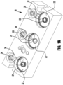
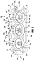
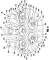
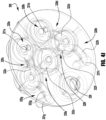
- the manifold body 100 includes a plurality of valve body segments 110a, 1 10b, 110c each having an upper perimeter wall portion 1 1 1a, 111b, 111c defining a valve cavity 112a, 112b, 112c, and a lower base portion 114a, 114b, 114c defining central flow ports 116a, 116b, 116c and offset flow ports 117a, 117b, 117c.
- the manifold body 100 further includes a plurality of conduit segments 120a, 120b, 120c, 120d having first leg (e.g., vertical) portions 121a, 121b, 121c, 121d defining conduit end portions or tube ends 123a, 123b, 123c, 123d for connection to fluid system components (e.g., conduits) in the fluid system (e.g., by welding or conduit fittings), and extending to second leg (e.g., horizontal) portions 122a, 122b, 122c, 122d extending to the flow ports 116a, 116b, 116c, 117a, 117b, 117c.
- a fitting connector e.g., a VCR ® metal gasket face seal fitting gland
- conduit end portions 123a, 123b, 123c, 123d of the illustrated embodiment extend substantially vertically upward, in other embodiments, the conduit end portions may extend in other directions, including, for example, at an upward non-vertical angle, horizontally, vertically downward, or at a downward non-vertical angle. Further, while such conduit end portions may be fabricated to extend in such directions, in other embodiments, the conduit end portions may be fabricated to extend in a first direction (e.g., vertically upward), and then be bent to extend in a second direction (e.g., horizontally). The conduit end portions may be specifically fabricated to facilitate such bending.
- Adjacent perimeter wall portions 111a, 111b, 111c of adjacent valve body segments 110a, 110b, 110c may be joined or fused together, for example, to facilitate manufacturing, to reduce overall size of the manifold body 100 and/or to strengthen or reinforce these wall portions. While the conduit end portions 123a, 123b, 123c may be similarly joined with one or more adjacent perimeter wall portions 111a, 111b, 111c, in the illustrated embodiment, the conduit end portions are spaced apart from the perimeter wall portions, and extend above an upper surface of the perimeter wall portions, to facilitate connection to the system (e.g., by welding or conduit fittings), for example, by allowing for lateral movement of the conduit end portions to accommodate tolerance deviations.
- the base portions 114a, 114b, 114c may be tapered (e.g., to have an outer diameter smaller than an outer diameter of the perimeter wall), for example, to reduce material usage and/or to provide clearance for one or more of the horizontal flow path portions 121a, 121b, 121c, 121d, such that a horizontal flow path portion of a conduit segment is at least partially laterally aligned with the valve cavity of at least one of the valve segments.
- branch conduit segments 120a, 120b, 120c connect with corresponding ones of the offset flow ports 117a, 117b, 117c
- common conduit segment 120d connects with each of the central flow ports 116a, 116b, 116c, for example, to provide a three-component mixing arrangement, or a distribution arrangement.
- manifold body configurations may be provided, including, for example, manifold bodies accommodating different numbers of valve assemblies. Additionally, many different manifold body configurations may be provided, including, for example, manifold bodies accommodating different numbers of valve assemblies, such as, for example, the valve and actuator assemblies of FIGS. 1 and 2 , and/or the valve and actuator assemblies of the above incorporated ⁇ 452 Patent.
- apertured mounting bosses 101 are provided to facilitate mounting of the manifold within a system (e.g., to a plate or other such base component of a fluid system).
- the mounting bosses may be joined or fused with an adjacent perimeter wall portion 111a, 111c to facilitate manufacturing, to reduce overall size of the manifold body 100 and/or to strengthen or reinforce these joined portions.
- the mounting bosses 101 may additionally be provided with tapers and/or counterbores, for example, to facilitate centering the head of the installed fastener (e.g., mounting screw, not shown).
- the manifold body may be adapted for other types of mounting or installation arrangements.
- the manifold body may be formed as an end plate or lid, for example, for a canister, to provide for sampling, purging, or other such fluid control to and/or from the canister.
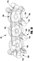
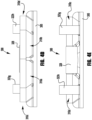
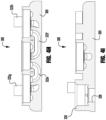
- FIGS. 4-4J illustrate an exemplary five-valve manifold body 300 (for use, for example with the valve and actuator assemblies of FIGS. 1 and 2 , or the valve and actuator assemblies of the above incorporated ⁇ 452 Patent), having a lower plate or lid portion 305 sized to be welded or otherwise sealed to an open end of a canister (not shown).
- the manifold body 300 includes five valve body segments 310a-e each having an upper perimeter wall portion 311a-e defining a valve cavity 312a-e, and a lower base portion 314a-e joined with the lower plate 305 and defining central flow ports 316a-e (with surrounding seating portions 315a-e) and offset flow ports 317a-e, 318c-d, and a plurality of conduit segments 320a-h (best shown in FIG. 4J ) extending from the flow ports 316a-e, 317a-e.
- first and second conduit segments 320a, 320b are defined by vertical passages 321a, 321b through the lower plate 305 from central flow ports 316a, 316b of first and second valve segments 3 10a, 310b to a lower surface 306 of the lower plate (e.g., for extraction of fluid samples from the canister).
- a third conduit segment 320c extends from an offset port 317a of the first valve segment 310a to a central port 316c of a third valve segment 310c, with a horizontal portion 322c of the conduit segment 320c being partially disposed in the lower plate 305.
- a fourth conduit segment 320d extends from an offset port 317b of the second valve segment to a central port 316d of a fourth valve segment 3 10d, with a horizontal portion 322d of the conduit segment 320d being partially disposed in the lower plate 305.
- a fifth conduit segment 320e extends from an offset port 317c of the third valve segment 320c to a central flow port 316e of a fifth valve segment 310e, with a horizontal portion 322e of the conduit segment 320e being partially disposed in the lower plate 305.
- a sixth conduit segment 320f extends from an offset port 317e of the fifth valve segment 310e to an offset port 317d of the fourth valve segment 310d, with a horizontal portion 322f of the conduit segment 320f being partially disposed in the lower plate 305.
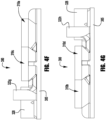
- a seventh conduit segment 320g includes a horizontal portion 322g extending from a second offset port 318c of the third valve segment 310c, and partially disposed in the lower plate 305, to a vertical end portion 321g extending upward from the lower plate 305 and defining a conduit end portions 323g providing an inlet/outlet port for connection to fluid system components (e.g., conduits) in the fluid system (e.g., by welding or conduit fittings).
- fluid system components e.g., conduits
- An eighth conduit segment 320h includes a horizontal portion 322h extending from a second offset port 318d of the fourth valve segment 310d, and partially disposed in the lower plate 305, to a vertical end portion 321h extending upward from the lower plate 305 and defining a conduit end portions 323h providing an inlet/outlet port for connection to fluid system components (e.g., conduits) in the fluid system (e.g., by welding or conduit fittings).
- fluid system components e.g., conduits
- a supply/drain port 328 may be provided with a passage 329 through the lower plate, for example, for quick filling or drainage of the canister.
- the port 328 may be plugged or otherwise sealed during normal operation of the canister.
- Adjacent perimeter wall portions 311 a-e of adjacent valve body segments 310a-e may be joined or fused, for example, to reduce overall size of the manifold body 300 and/or to strengthen or reinforce these wall portions. While the conduit end portions 323g, 323h may be similarly joined with one or more adjacent perimeter wall portions 311a-e, in the illustrated embodiment, the conduit end portions are spaced apart from the perimeter wall portions, and extend above an upper surface of the perimeter wall portions, to facilitate connection to the system (e.g., by welding or conduit fittings), for example, by allowing for lateral movement of the conduit end portions to accommodate tolerance deviations.
- the base portions 314a-e may be tapered, for example, to reduce material usage and/or to provide clearance for one or more of the horizontal flow path portions.
- a fluid component body e.g., a manifold body
- a fluid component body may make the body difficult to manufacture using conventional machining, molding, or casting techniques.
- a fluid component body for example, the manifold bodies 100, 300 of FIGS. 3-3J and 4-4J , may be fabricated using additive manufacturing to produce a monolithic body having discrete, but partially joined or fused, valve segments and conduit segments.
- additive manufacturing techniques include, for example: laser powder bed fusion (direct metal laser sintering or "DMLS,” selective laser sintering/melting or “SLS/SLM,” or layered additive manufacturing or “LAM”), electron beam powder bed fusion (electron beam melting or “EBM”), ultrasonic additive manufacturing ("UAM”), or direct energy deposition (laser powder deposition or “LPD,” laser wire deposition or “LWD,” laser engineered net-shaping or “LENS,” electron beam wire deposition).
- DMLS direct metal laser sintering or "DMLS,” selective laser sintering/melting or “SLS/SLM,” or layered additive manufacturing or “LAM”
- EBM electron beam powder bed fusion
- UAM ultrasonic additive manufacturing
- LPD laser powder deposition
- LWD laser wire deposition
- LENS laser engineered net-shaping
- conduit end portions 323g, 323h of the illustrated embodiment extend substantially vertically upward, in other embodiments, the conduit end portions may extend in other directions, including, for example, at an upward non-vertical angle, horizontally, vertically downward, or at a downward non-vertical angle. Further, while such conduit end portions may be fabricated to extend in such directions, in other embodiments, the conduit end portions may be fabricated to extend in a first direction (e.g., vertically upward, horizontally), and then be bent to extend in a second direction (e.g., horizontally, vertically). For example, for components having significant longitudinal, lateral, and vertical dimensions, 3D printing or other additive manufacturing can be more time consuming and more costly.
- a 3D printed fluid component extending primarily in first and second dimensions may be configured to have one or more portions (e.g., one or more end ports or connecting ports) bent to extend primarily or significantly in a third dimension (e.g., vertical), thereby providing a finished fluid component having significant longitudinal, lateral, and vertical dimensions while reducing 3D printing time and cost.
- the conduit end portions may be specifically fabricated to facilitate such bending.
- the conduit end portion may be formed or fabricated to have a reduced wall thickness on the portions of the conduit end portion subject to bending (e.g., at the axial location of the bend, and/or in the direction of the bend).
- the conduit end portion may be provided with a cross-sectional shape selected to facilitate bending-for example, an oblong or high aspect ratio cross-section (e.g., oval-shaped) having a minor diameter oriented in the direction of the intended bend.
- a port or conduit portion formed to be bent in a post-fabrication operation may be shaped and/or orientated to promote a hinging action for desired bending of the conduit.
- an external surface of the fluid component body may be provided with a bending limit feature, such as, for example, a boss, wall, protrusion, or other body structure sized and positioned to limit bending of the conduit end portion to a desired angle (e.g., by abutting an outer surface of the conduit end portion at the desired angle).
- a bending limit feature such as, for example, a boss, wall, protrusion, or other body structure sized and positioned to limit bending of the conduit end portion to a desired angle (e.g., by abutting an outer surface of the conduit end portion at the desired angle).
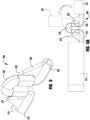
- FIG. 5 illustrates an exemplary port or conduit 500 of a 3D printed fluid component.
- the conduit 500 includes first and second longitudinally extending portions 512, 522, first and second vertically extending portions 515, 525, and a U-shaped portion 530 connecting the vertically extending portions.
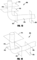
- the longitudinally extending portions 512, 522 may extend to other portions of the fluid component (as schematically represented at 511 and 521 in FIG. 5A ), such as valve bodies or end fittings.
- the vertically extending portions 515, 525 are provided with an oblong or high aspect ratio cross-section (e.g., oval-shaped) to facilitate bending of the second longitudinally extending portion into an orientation substantially orthogonal to the first longitudinally extending portion, as shown in FIGS. 5A and 6 .
- the port may additionally or alternatively include a U-shaped portion having an oblong or high aspect ratio cross-section (e.g., oval-shaped) to facilitate bending at the U-shaped portion.
- one or more cross-sectional portions (e.g., oblong cross-sectional portions, as described herein) of a 3D printed conduit may be fabricated with internal supports (e.g., an internal lattice) configured to maintain the shape of the conduit portion during 3D printing and/or bending.
- internal supports e.g., an internal lattice
- the internal supports may be removed, for example, by using abrasive flow machining (AFM), by which an abrasive-laden fluid is pumped through the conduit to break or erode away the internal supports.
- AFM abrasive flow machining
- the internal supports may be removed (e.g., by AFM, as discussed above) prior to bending, for example, to provide for greater flexibility of the conduit.
- FIG. 7 illustrates an exemplary cross-section of an oblong conduit portion 508 including internal lattice supports 509.
- the conduit or port may be bent using tools configured to bend the second longitudinal portion, with respect to the first longitudinal portion, to a consistent desired orientation (e.g., substantially orthogonal).
- the fluid component may be provided with one or more external stop portions configured to provide a positive stop to the bending operation when the longitudinal portions have reached the desired bent orientations.
- first and second stop portions 514, 524 extend from exterior surfaces of the longitudinal conduit portions and are sized to contact exterior surfaces of the U-shaped conduit portion 530 (as shown in FIG. 6 ) when the vertical conduit portions 515, 525 have bent to position the longitudinal conduit portions 512, 522 in the desired orientation.
- the stop portions may be sized or positioned to allow for slight over-bending beyond the desired orientation, for example, to account for spring back inherent in the material used (e.g., stainless steel or other metals).
- FIGS. 8 and 9 illustrate an exemplary 3D printed conduit 600 having first and second longitudinal portions 612, 622 and a central bending portion 630 having a reduced wall thickness to facilitate bending, and a row of spaced apart protrusions 631, disposed along a surface intended to be the inner diameter of the bend, that engage each other (see FIG. 9 ) at a desired bend orientation (e.g., approximately 90°), including adjacent stop portions 632 (see FIG. 8A ) that engage each other to provide a controlled, uniform bend with an engineered bend radius, thereby preventing kinking or other bending artifacts that may result from a nonuniform bend.
- the stop portions 632 may be sized or positioned to allow for slight over-bending beyond the desired orientation, to account for spring back inherent in the material used (e.g., stainless steel or other metals).
- FIG. 10 illustrates an exemplary 3D printed conduit 700, similar to the conduit 600 of FIGS. 8 and 9 , having snap-fit latch portions 714, 724 extending from the first and second longitudinal portions of the conduit.
- the latch portions 714, 724 snap into interlocking engagement with each other to secure the bent conduit in the desired configuration. While the conduit 700 is shown with spaced apart bend controlling protrusions 731, similar to the protrusions 631 of the conduit 600 of FIGS. 8 and 9 , in other embodiments, bendable conduits having snap-fit latch portions may be provided without additional bend limiting features, or with different bend limiting features.
- additive manufacturing of the fluid component body may facilitate incorporation of additional features.
- additive manufacturing may be utilized to produce one or more internal flow paths in a fluid component body that are configured to include one or more flow path discontinuities along one or more legs of the internal flow path, including, for example, deviations in flow path cross-sectional shape, cross-sectional size, flow path center line, and internal surface characteristics.
- Many different types of flow path discontinuities may be provided to facilitate a variety of flow conditions.
- fluid system flow paths require a very smooth or highly polished surface finish, for example, to minimize the generation of particle contamination or fluid entrapment.
- polishing may be accomplished using abrasive flow machining (AFM) or abrasive flow finishing (AFF), by which an abrasive-laden fluid is pumped through a workpiece to remove or erode surface material from rough internal flow path surfaces to produce smoother, polished surfaces.
- AFM abrasive flow machining
- AFF abrasive flow finishing
- extended internal flow paths may be adapted to provide flow path discontinuities configured to provide increases in one or more of flow shear, flow compression, and flow incidence for accelerated erosion of the flow path surfaces.
- a first portion of the flow path e.g., a first leg or vertical portion 410 of the flow path 400
- a flow path may be provided with a varying cross-sectional shape, for example, to increase the shear action of the abrasive laden fluid against the flow path walls.
- the cross-sectional shape of the flow path may be varied between two or more suitable shapes, including, for example, circular, oval, square, rectangular, and triangular, as well as more complex shapes, including a teardrop shape.
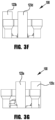
- FIG. 12 illustrates an exemplary elbow shaped flow path 400a having a circular cross-section at a first cross-sectional plane 411a (e.g., along the first leg flow path portion 410a) and a teardrop cross-section at a second cross-sectional plane 421a (e.g., along the second leg flow path portion 420a), with the transition from circular to teardrop cross-section occurring along the bend in the elbow.
- horizontal flow path portions 122a, 122d are provided with a similar teardrop-shaped cross-section, as shown in FIG. 3I .
- additional or alternative cross-sectional shape changes may be provided, for example, along the length of the first leg flow path portion 410a and/or along the length of the second leg flow path portion 420a.
- a flow path of varying cross-sectional shape may, but need not, be configured to have a substantially constant cross-sectional area along the length of the flow path, for example, to maintain the desired flow properties while providing increased shear action against the flow path walls as a result of the changing cross-sectional shape.
- a flow path may be provided with a varying cross-sectional area, for example, to increase compression of the abrasive laden fluid at the smaller cross-sectional area (or "necked down") portions, to increase the erosive effects at or near these necked down portions.
- FIG. 13 illustrates an exemplary elbow shaped flow path 400b having first leg and second leg flow path portions 410b, 420b with varying cross-sectional areas at various cross-sectional planes 411b, 412b, 421b, 422b along the length of the flow path 400b.
- the first leg flow path portion 410b varies in cross-sectional area between a maximum area cross-sectional plate 411b and a minimum area cross-sectional plane 412b
- the second leg flow path portion 420b varies in cross-sectional area between a maximum area cross-sectional plate 421b and a minimum area cross-sectional plane 422b
- portions of the flow path e.g., the entire first leg flow path portion
- a flow path of varying cross-sectional size may, but need not, be configured to have a substantially constant cross-sectional shape (e.g., circular) along the length of the flow path. Flow through the flow path may be primarily limited by the smallest cross-sectional area along the length of the flow path, and the flow path may be sized accordingly.
- longer flow channels in a fluid component body may be configured to provide progressively restricted flow in the direction of fluid flow (e.g., inlet to outlet, or inlet to port center point), for example, to improve the efficacy of abrasive flow finishing.
- the internal surfaces may be gradually tapered radially inward, or more sharply tapered (e.g., stepped) radially inward, or by a combination of two or more types of flow path profiles.
- the desired amount of flow path restriction may be based at least in part on the relative pressure loss of the abrasive laden fluid (which may be a function of viscosity and frictional losses, for example, due to abrasive cutting forces), with more aggressive media (with higher pressure losses) potentially benefitting from more aggressive flow path tapering.
- This restriction in flow area may be correlated to a length of the passage, for example, with the flow path area reduction being quantified as a percentage reduction in area per inch of port length (e.g., 15% - 30% per inch of port length).
- a flow path may be provided with non-linear flow path portions having a varying center line (i.e., non-coaxial), for example, to change direction of the flow path to affect the angle of incidence of the abrasive laden fluid against the walls of the flow path, to increase the erosive effects on the flow path walls.
- FIG. 14 illustrates an exemplary elbow shaped flow path 400c having first leg and second leg flow path portions 410c, 420c with a curved helical flow path resulting in variations in the center line locations at various cross-sectional planes 411c, 412c, 421c, 422c along the length of the flow path 400c.
- first leg and second leg flow path portions 410c, 420c are provided with continuously varying center lines resulting from a continuous helical pattern.
- portions of the flow path e.g., the entire first leg flow path portion
- a flow path of varying cross-sectional size may, but need not, be configured to have a substantially constant cross-sectional shape (e.g., circular) and a substantially constant cross-sectional size along the length of the flow path.
- a flow path maybe provided with two or more of: (a) a varying cross-sectional shape, (b) a varying cross-sectional area, and (c) a varying center line.
- FIG. 15 illustrates an exemplary elbow shaped flow path 400d having first leg and second leg flow path portions 410d, 420d with varying cross-sectional shapes, areas, and center lines at various cross-sectional planes 411d, 412d, 421d, 422d along the length of the flow path 400d.
- Additive manufacturing of the fluid component body may facilitate incorporation of additional features.
- the internal flow path surfaces of a fluid component body may be textured to affect fluid flow properties, such as, for example, altering turbulent flow conditions and/or reducing the propensity for contaminants or process fluid adsorbing to the internal surfaces.
- a flow path may be formed with an internal surface provided with a pattern of surface discontinuities, such as, for example, dimples, raised protuberances, grooves, or other such surface features. These surface discontinuities may, for example, be quantified based on depth and/or surface area (e.g., axial length, circumferential width, diameter) as a percentage of a flow path dimension, such as, for example, bore diameter.
- a flow path internal surface is provided with an array of spherical dimples having a spherical radius of approximately 1/10 th of the effective bore diameter, and a dimple depth of approximately 1/50 th of the effective bore diameter.
- Such dimples may, for example, be spaced to achieve approximately 50% surface density on the bore inner diameter.
- additive manufacturing may be utilized to provide portions of the flow path(s) that are layered with a material or materials having a desired thermal conductivity, corrosion resistance, hardness, or other such properties.
Landscapes
- Engineering & Computer Science (AREA)
- General Engineering & Computer Science (AREA)
- Mechanical Engineering (AREA)
- Manufacturing & Machinery (AREA)
- Chemical & Material Sciences (AREA)
- Materials Engineering (AREA)
- Valve Housings (AREA)
- Check Valves (AREA)
Applications Claiming Priority (4)
| Application Number | Priority Date | Filing Date | Title |
|---|---|---|---|
| US201862691171P | 2018-06-28 | 2018-06-28 | |
| US201962801383P | 2019-02-05 | 2019-02-05 | |
| EP19739465.3A EP3814660B1 (de) | 2018-06-28 | 2019-06-19 | Fluidkomponentenkörper und verfahren zu seiner herstellung |
| PCT/US2019/037857 WO2020005656A1 (en) | 2018-06-28 | 2019-06-19 | Fluid component body and method of making same |
Related Parent Applications (2)
| Application Number | Title | Priority Date | Filing Date |
|---|---|---|---|
| EP19739465.3A Division-Into EP3814660B1 (de) | 2018-06-28 | 2019-06-19 | Fluidkomponentenkörper und verfahren zu seiner herstellung |
| EP19739465.3A Division EP3814660B1 (de) | 2018-06-28 | 2019-06-19 | Fluidkomponentenkörper und verfahren zu seiner herstellung |
Publications (2)
| Publication Number | Publication Date |
|---|---|
| EP4530518A2 true EP4530518A2 (de) | 2025-04-02 |
| EP4530518A3 EP4530518A3 (de) | 2025-06-18 |
Family
ID=67253994
Family Applications (2)
| Application Number | Title | Priority Date | Filing Date |
|---|---|---|---|
| EP25157586.6A Pending EP4530518A3 (de) | 2018-06-28 | 2019-06-19 | Fluidkomponentenkörper und verfahren zu seiner herstellung |
| EP19739465.3A Active EP3814660B1 (de) | 2018-06-28 | 2019-06-19 | Fluidkomponentenkörper und verfahren zu seiner herstellung |
Family Applications After (1)
| Application Number | Title | Priority Date | Filing Date |
|---|---|---|---|
| EP19739465.3A Active EP3814660B1 (de) | 2018-06-28 | 2019-06-19 | Fluidkomponentenkörper und verfahren zu seiner herstellung |
Country Status (7)
| Country | Link |
|---|---|
| US (2) | US11168801B2 (de) |
| EP (2) | EP4530518A3 (de) |
| KR (2) | KR20210028217A (de) |
| CN (2) | CN112400079A (de) |
| SG (1) | SG11202012859WA (de) |
| TW (2) | TWI791858B (de) |
| WO (1) | WO2020005656A1 (de) |
Families Citing this family (6)
| Publication number | Priority date | Publication date | Assignee | Title |
|---|---|---|---|---|
| WO2020161096A1 (en) * | 2019-02-04 | 2020-08-13 | Kanthal Ab | Tube, method of manufacturing tube, and related devices |
| DE102019130078A1 (de) * | 2019-11-07 | 2021-05-12 | Auto-Kabel Management Gmbh | Kraftfahrzeugenergieleitung sowie ein Verfahren zum Biegen einer Kraftfahrzeugenergieleitung |
| EP3828045B1 (de) * | 2019-11-29 | 2023-09-13 | KNORR-BREMSE Systeme für Schienenfahrzeuge GmbH | 3d-gedruckter verteiler für eine pneumatische schalttafel eines schienenfahrzeugs |
| US12123808B2 (en) | 2019-12-20 | 2024-10-22 | Swagelok Company | Fluid component body with leak test passages |
| US11920718B2 (en) | 2021-06-30 | 2024-03-05 | Raytheon Company | Additive manufactured liquid manifold with orifice |
| CN117052953B (zh) * | 2023-10-12 | 2024-01-30 | 海普瑞(常州)洁净系统科技有限公司 | 一种半导体用三联阀及其工作方法 |
Citations (1)
| Publication number | Priority date | Publication date | Assignee | Title |
|---|---|---|---|---|
| US9863542B2 (en) | 2013-02-01 | 2018-01-09 | Swagelok Company | Diaphragm valve with welded diaphragm seat carrier |
Family Cites Families (27)
| Publication number | Priority date | Publication date | Assignee | Title |
|---|---|---|---|---|
| US4589595A (en) * | 1981-04-04 | 1986-05-20 | Havens International, Inc. | Pressure compensated emitter |
| US4991293A (en) * | 1989-08-02 | 1991-02-12 | Proprietary Technology, Inc. | Means for providing very small bend radii in the tube-like structures |
| US5378524A (en) * | 1991-05-28 | 1995-01-03 | Blood; Charles L. | Friction reducing surface and devices employing such surfaces |
| DE19511395A1 (de) * | 1995-03-28 | 1996-10-02 | Buerkert Werke Gmbh & Co | Modulares Ventilsystem zum Sammeln und Verteilen von Flüssigkeiten |
| RU2083824C1 (ru) | 1995-06-13 | 1997-07-10 | Научно-исследовательский институт высоких напряжений при Томском политехническом университете | Способ разрушения горных пород |
| US5765591A (en) * | 1995-11-20 | 1998-06-16 | Argonaut Technologies, Inc. | Valve apparatus and method for distributing fluids |
| WO1998010229A1 (en) * | 1996-09-02 | 1998-03-12 | Aktiebolaget Electrolux | A gas valve |
| DE29909715U1 (de) * | 1999-06-04 | 1999-09-02 | Anton Hummel Verwaltungs Gmbh, 79183 Waldkirch | Wellschlauch mit einer Halterung |
| US6467502B1 (en) * | 2000-07-26 | 2002-10-22 | Snap-Tite Technologies, Inc. | Manifold and method of making same |
| US6619321B2 (en) * | 2000-08-18 | 2003-09-16 | Parker-Hannifin Corporation | Stream switching system |
| US20040118466A1 (en) * | 2002-12-19 | 2004-06-24 | Eaton Corporation | Electro-hydraulic manifold assembly and pressure sensor therefor |
| US7048008B2 (en) | 2004-04-13 | 2006-05-23 | Ultra Clean Holdings, Inc. | Gas-panel assembly |
| JP2006009969A (ja) * | 2004-06-25 | 2006-01-12 | Kitz Sct:Kk | 集積化ガス制御装置用流路ブロックとその製造方法並びに集積化ガス制御装置 |
| US7785514B2 (en) * | 2006-05-18 | 2010-08-31 | Mccarthy Peter T | Snorkels, flexible tubes, mouthpieces and methods |
| US20080092975A1 (en) * | 2006-09-15 | 2008-04-24 | Grimes David L | Heater core connector |
| DE102008027796A1 (de) * | 2008-06-11 | 2009-12-17 | Honeywell Technologies Sarl | Gasregelgerät |
| WO2014113808A2 (en) * | 2013-01-21 | 2014-07-24 | Webster William Gardiner Iii | Duct fitting apparatus with reduced flow pressure loss and method of formation thereof |
| US9968930B2 (en) * | 2013-04-04 | 2018-05-15 | Surnetics, Llc | Microfluidic products with controlled fluid flow |
| DE102013209727A1 (de) * | 2013-05-24 | 2014-11-27 | Robert Bosch Gmbh | Hydraulikblock für eine schlupfgeregelte Fahrzeugbremsanlage |
| US9562632B1 (en) * | 2013-10-11 | 2017-02-07 | United Services Automobile Association (Usaa) | Fabricating conduits |
| US9759356B2 (en) * | 2014-07-03 | 2017-09-12 | United Technologies Corporation | Insulated flowpath assembly |
| JP6539482B2 (ja) * | 2015-04-15 | 2019-07-03 | 株式会社フジキン | 遮断開放器 |
| US9879566B2 (en) * | 2015-07-07 | 2018-01-30 | Honeywell International Inc. | Turbine engine couplings and methods for manufacturing turbine engine couplings |
| EP3181978B1 (de) * | 2015-12-16 | 2020-05-06 | FASTER S.r.l. | Mehrfachkupplungsverteiler für schnellkupplungen |
| US9879795B2 (en) | 2016-01-15 | 2018-01-30 | Lam Research Corporation | Additively manufactured gas distribution manifold |
| US10215317B2 (en) * | 2016-01-15 | 2019-02-26 | Lam Research Corporation | Additively manufactured gas distribution manifold |
| WO2020163190A1 (en) * | 2019-02-05 | 2020-08-13 | Swagelok Company | Integrated actuator manifold for multiple valve assembly |
-
2019
- 2019-06-19 KR KR1020217002867A patent/KR20210028217A/ko not_active Ceased
- 2019-06-19 EP EP25157586.6A patent/EP4530518A3/de active Pending
- 2019-06-19 US US16/445,365 patent/US11168801B2/en active Active
- 2019-06-19 SG SG11202012859WA patent/SG11202012859WA/en unknown
- 2019-06-19 CN CN201980043188.9A patent/CN112400079A/zh active Pending
- 2019-06-19 EP EP19739465.3A patent/EP3814660B1/de active Active
- 2019-06-19 KR KR1020237044707A patent/KR20240005200A/ko not_active Ceased
- 2019-06-19 CN CN202310682950.6A patent/CN116697088A/zh active Pending
- 2019-06-19 WO PCT/US2019/037857 patent/WO2020005656A1/en not_active Ceased
- 2019-06-25 TW TW108122167A patent/TWI791858B/zh active
- 2019-06-25 TW TW112106727A patent/TW202323584A/zh unknown
-
2021
- 2021-10-13 US US17/499,919 patent/US11965605B2/en active Active
Patent Citations (1)
| Publication number | Priority date | Publication date | Assignee | Title |
|---|---|---|---|---|
| US9863542B2 (en) | 2013-02-01 | 2018-01-09 | Swagelok Company | Diaphragm valve with welded diaphragm seat carrier |
Also Published As
| Publication number | Publication date |
|---|---|
| US11965605B2 (en) | 2024-04-23 |
| EP3814660B1 (de) | 2025-08-06 |
| EP4530518A3 (de) | 2025-06-18 |
| EP3814660C0 (de) | 2025-08-06 |
| TWI791858B (zh) | 2023-02-11 |
| CN112400079A (zh) | 2021-02-23 |
| TW202000977A (zh) | 2020-01-01 |
| CN116697088A (zh) | 2023-09-05 |
| TW202323584A (zh) | 2023-06-16 |
| WO2020005656A1 (en) | 2020-01-02 |
| KR20210028217A (ko) | 2021-03-11 |
| US11168801B2 (en) | 2021-11-09 |
| SG11202012859WA (en) | 2021-01-28 |
| US20200003318A1 (en) | 2020-01-02 |
| US20220042616A1 (en) | 2022-02-10 |
| KR20240005200A (ko) | 2024-01-11 |
| EP3814660A1 (de) | 2021-05-05 |
Similar Documents
| Publication | Publication Date | Title |
|---|---|---|
| EP4530518A2 (de) | Fluidkomponentenkörper und verfahren zu seiner herstellung | |
| AU2007245151B2 (en) | Fluid pressure reduction devices | |
| JP6283018B2 (ja) | 流れ矯正弁座および流れ矯正弁座を備えた制御弁 | |
| US11624455B2 (en) | Valve trim | |
| US6948665B2 (en) | Fuel injector including an orifice disc, and a method of forming the orifice disc with an asymmetrical punch | |
| EP1735557A1 (de) | Vorrichtungen zur verringerung von fluiddruck | |
| US7086615B2 (en) | Fuel injector including an orifice disc and a method of forming an oblique spiral fuel flow | |
| CN115427719A (zh) | 用于控制阀的三维曲折路径流量元件 | |
| EP1180627A1 (de) | Sperrventil für hohe differenzdrucke | |
| EP1644632A1 (de) | Kraftstoffinjektor mit einer spritzlochplatte mit plattensegmenten mit unterschiedlichen winkeln | |
| CN222717510U (zh) | 滑块组件及阀门 | |
| US20060192036A1 (en) | Fuel injector including a multifaceted dimple for an orifice disc with a reduced footprint of the multifaceted dimple | |
| KR101966385B1 (ko) | 엘보 제조방법 | |
| CN221278543U (zh) | 一种浮子式单向阀及空调系统 | |
| CN113195951A (zh) | 用于制造具有完全包封的座环的块体锻造的旋启式止回阀本体的方法 | |
| CN223152962U (zh) | 一种高稳定性的铝阀座 | |
| KR102726710B1 (ko) | 밸브 몸체 및 그 제조 방법 | |
| JP7532685B2 (ja) | 往復式圧縮機における取り外し可能な固定ガイド付き圧縮機弁組立体 | |
| US12286950B2 (en) | Working method of orifice and fuel injection valve | |
| CN118318124A (zh) | 用于防止回流的装置 | |
| CN115127260A (zh) | 膨胀阀及用于该膨胀阀的动力元件 | |
| JP2004060592A (ja) | 噴射装置、噴孔部材の製造装置および噴孔部材の製造方法 |
Legal Events
| Date | Code | Title | Description |
|---|---|---|---|
| PUAI | Public reference made under article 153(3) epc to a published international application that has entered the european phase |
Free format text: ORIGINAL CODE: 0009012 |
|
| STAA | Information on the status of an ep patent application or granted ep patent |
Free format text: STATUS: THE APPLICATION HAS BEEN PUBLISHED |
|
| AC | Divisional application: reference to earlier application |
Ref document number: 3814660 Country of ref document: EP Kind code of ref document: P |
|
| AK | Designated contracting states |
Kind code of ref document: A2 Designated state(s): AL AT BE BG CH CY CZ DE DK EE ES FI FR GB GR HR HU IE IS IT LI LT LU LV MC MK MT NL NO PL PT RO RS SE SI SK SM TR |
|
| REG | Reference to a national code |
Ref country code: DE Ref legal event code: R079 Free format text: PREVIOUS MAIN CLASS: F16L0043020000 Ipc: F16K0027000000 |
|
| PUAL | Search report despatched |
Free format text: ORIGINAL CODE: 0009013 |
|
| AK | Designated contracting states |
Kind code of ref document: A3 Designated state(s): AL AT BE BG CH CY CZ DE DK EE ES FI FR GB GR HR HU IE IS IT LI LT LU LV MC MK MT NL NO PL PT RO RS SE SI SK SM TR |
|
| RIC1 | Information provided on ipc code assigned before grant |
Ipc: F16L 43/02 20060101ALI20250513BHEP Ipc: F16L 11/15 20060101ALI20250513BHEP Ipc: F16L 11/12 20060101ALI20250513BHEP Ipc: B33Y 80/00 20150101ALI20250513BHEP Ipc: B22F 5/10 20060101ALI20250513BHEP Ipc: B33Y 10/00 20150101ALI20250513BHEP Ipc: F16L 51/04 20060101ALI20250513BHEP Ipc: B29C 64/00 20170101ALI20250513BHEP Ipc: F16K 27/00 20060101AFI20250513BHEP |