EP4530503A1 - Verformbarer verschlussstopfen und verfahren zum verschliessen eines hohlraums mit einem solchen verschlussstopfen - Google Patents
Verformbarer verschlussstopfen und verfahren zum verschliessen eines hohlraums mit einem solchen verschlussstopfen Download PDFInfo
- Publication number
- EP4530503A1 EP4530503A1 EP24198229.7A EP24198229A EP4530503A1 EP 4530503 A1 EP4530503 A1 EP 4530503A1 EP 24198229 A EP24198229 A EP 24198229A EP 4530503 A1 EP4530503 A1 EP 4530503A1
- Authority
- EP
- European Patent Office
- Prior art keywords
- casing
- cavity
- rod
- sealing plug
- sealing
- Prior art date
- Legal status (The legal status is an assumption and is not a legal conclusion. Google has not performed a legal analysis and makes no representation as to the accuracy of the status listed.)
- Pending
Links
Images


Classifications
-
- F—MECHANICAL ENGINEERING; LIGHTING; HEATING; WEAPONS; BLASTING
- F16—ENGINEERING ELEMENTS AND UNITS; GENERAL MEASURES FOR PRODUCING AND MAINTAINING EFFECTIVE FUNCTIONING OF MACHINES OR INSTALLATIONS; THERMAL INSULATION IN GENERAL
- F16J—PISTONS; CYLINDERS; SEALINGS
- F16J13/00—Covers or similar closure members for pressure vessels in general
- F16J13/02—Detachable closure members; Means for tightening closures
- F16J13/14—Detachable closure members; Means for tightening closures attached exclusively by spring action or elastic action
-
- B—PERFORMING OPERATIONS; TRANSPORTING
- B62—LAND VEHICLES FOR TRAVELLING OTHERWISE THAN ON RAILS
- B62D—MOTOR VEHICLES; TRAILERS
- B62D25/00—Superstructure or monocoque structure sub-units; Parts or details thereof not otherwise provided for
- B62D25/24—Superstructure sub-units with access or drainage openings having movable or removable closures; Sealing means therefor
-
- B—PERFORMING OPERATIONS; TRANSPORTING
- B64—AIRCRAFT; AVIATION; COSMONAUTICS
- B64C—AEROPLANES; HELICOPTERS
- B64C1/00—Fuselages; Constructional features common to fuselages, wings, stabilising surfaces or the like
- B64C1/26—Attaching the wing or tail units or stabilising surfaces
-
- B—PERFORMING OPERATIONS; TRANSPORTING
- B64—AIRCRAFT; AVIATION; COSMONAUTICS
- B64C—AEROPLANES; HELICOPTERS
- B64C3/00—Wings
- B64C3/34—Tanks constructed integrally with wings, e.g. for fuel or water
-
- B—PERFORMING OPERATIONS; TRANSPORTING
- B64—AIRCRAFT; AVIATION; COSMONAUTICS
- B64C—AEROPLANES; HELICOPTERS
- B64C7/00—Structures or fairings not otherwise provided for
-
- F—MECHANICAL ENGINEERING; LIGHTING; HEATING; WEAPONS; BLASTING
- F16—ENGINEERING ELEMENTS AND UNITS; GENERAL MEASURES FOR PRODUCING AND MAINTAINING EFFECTIVE FUNCTIONING OF MACHINES OR INSTALLATIONS; THERMAL INSULATION IN GENERAL
- F16L—PIPES; JOINTS OR FITTINGS FOR PIPES; SUPPORTS FOR PIPES, CABLES OR PROTECTIVE TUBING; MEANS FOR THERMAL INSULATION IN GENERAL
- F16L55/00—Devices or appurtenances for use in, or in connection with, pipes or pipe systems
- F16L55/10—Means for stopping flow in pipes or hoses
- F16L55/12—Means for stopping flow in pipes or hoses by introducing into the pipe a member expandable in situ
- F16L55/128—Means for stopping flow in pipes or hoses by introducing into the pipe a member expandable in situ introduced axially into the pipe or hose
- F16L55/132—Means for stopping flow in pipes or hoses by introducing into the pipe a member expandable in situ introduced axially into the pipe or hose the closure device being a plug fixed by radially deforming the packing
Definitions
- the present invention relates to a deformable sealing plug and a method for sealing a cavity using such a sealing plug, in particular a cavity of a primary structure of an aircraft such as a wing box.
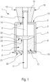
- the plug 1 is configured with a shape intended to cooperate with the walls of the cavity 2.
- a shape intended to cooperate with the walls of the cavity 2 By “cooperate” is meant that the general shape of the plug 1 (in particular that of the casing 3) corresponds approximately to the shape of the cavity 2, being slightly smaller than the latter.
- the plug 1 can be inserted by hand into the cavity 2 by being slid therein.
- the shape of the plug 1 is intended so that it fits the cavity 2 by being in contact with the walls 26 and 27.
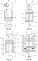
- a gap between the undeformed side wall 4 of the casing 3 and the walls 26 and 27 of the cavity 2 is deliberately shown in an exaggerated manner on the Figure 2C and the 2D figure .
- step E2 the deformation of the casing 3 and/or the movement of the non-return part 22 (driven by the movement of the rod 9) drives the viscous seal 17 outside the casing 3 through the orifices 8 as illustrated by two arrows F on the 2D figure
- the viscous seal 17 is then pressed between the walls of the casing 3 and the walls of the cavity 2, which allows it to spread throughout the space remaining between the plug 1 and the walls of the cavity 2, in particular in small spaces which could form between the casing 3 and the walls of the cavity 2 during step E2.
- the polymerization step E3 is implemented to allow said viscous seal 17 to polymerize.
- the polymerization of the viscous seal 17 at room temperature makes it possible to finalize the sealing. of cavity 2. In particular, it helps to reinforce the quality of the seal and it contributes to keeping the plug 1 in place in cavity 2.
- the method P comprises an intermediate step E4, implemented after step E1 and before step E2.
- This step E4 comprises the placement of an intermediate part 28 in the cavity 2, as shown in the Figure 6
- This intermediate part 28 comprises a first end 29 configured to bear against the stopper 1 and a second end 30 configured to project outside the cavity 2.
- the end 29 of the intermediate part 28 is placed in abutment against the bearing surface 21 of the rigid cover 19.
- the end 30 of the intermediate part 28 is provided with a surface 31 capable of serving as a bearing surface for pulling the rod 9.
- the intermediate part 28 thus arranged with the face 31 projecting outside the cavity 2, makes it possible to obtain a bearing surface for pulling the rod 9 which is easily accessible. This is particularly advantageous in configurations where access to the cavity 2 is limited and/or when the pulling tool cannot be introduced up to the stopper 1 to bear directly on the bearing surface 21 of the rigid cover 19.
- the intermediate part 28 may, in particular, have a particular shape, for example bent, so that the face 31 projects outside the cavity 2 with an orientation adapted to carry out the pulling of the rod 9.
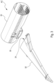
- a preferred application for the cap 1 is shown in the Figure 3 to the Figure 6 . It concerns a junction zone between primary structures of a wing 32 and a fuselage 33 of an AC aircraft (partially shown on the figure 3 ). More particularly, it is a junction zone between a wing box 34 of the wing 32 and a central box 35 of the fuselage 33.
- the assembly of the wing box 34 and the central box 35 involves a complex superposition of several metal or composite material plates with particular shapes.
- a plate 36 of the wing box 34 comes opposite a plate 37 of the central box 35.
- the assembly constraints mean that the plates 36 and 37 are spaced from each other, creating a space between them.
- a plate 38 is fixed over the plates 36 and 37, covering said space between them.
- the plate 38 is shown transparent on the Figure 4 so as to visualize the space at the interface between plates 36 and 37.
- plate 38 forms a conduit (or a chimney) of substantially rectangular section, highlighted in the Figure 4 in a frame C.
- This conduit arranged between plates 36, 37 and 38 corresponds to cavity 2 which we wish to plug using plug 1.
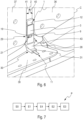
- the area framed by box C is shown enlarged on the Figure 5 and the Figure 6 .
- the cavity 2 is delimited by faces 40, 41 and 42.
- the faces 40 and 41 correspond to slices, respectively of the plates 36 and 37, arranged opposite each other.
- the face 42 corresponds to a face of a rear plate (substantially parallel to the plate 38) arranged on the plates 36 and 37 from the inside of the wing box 34.
- a last face delimiting the cavity 2 corresponds to the face of the plate 38 arranged on the plates 36 and 37 from the outside of the wing box 34.
- the plate 38 is not shown on the Figure 5 and the Figure 6 .
- the cavity 2 has, at one of its ends, an opening 43 opening towards the outside of the wing box 34 opposite an angle iron 39. At its other end (not shown), the cavity 2 opens inside the wing box 34.
- the plug 1 is positioned in the cavity 2 near the opening 43.
- a space between the angle iron 39 and the opening 42 allows the plug 1 to be inserted, if need, by bending it (thanks to its flexible general structure).
- the end of the plug 1 comprising the head 12 is arranged towards the inside of the cavity 2 and the end comprising the end 11 to be pulled is arranged towards the opening 43.
- the rod 9 is provided with a length adapted to protrude outside the cavity 2.
- the intermediate part 28 is arranged in the cavity 2 bearing against the stopper 1. More precisely, the end 29 of the intermediate part 28 is inserted into the cavity 2 until it comes to bear against the bearing surface 21 of the rigid cover 19.
- the intermediate part 28 has a length adapted so that its end 30 protrudes outside the cavity 2 when the end 29 is bearing against the stopper 1.
- the intermediate part 28 has a bent shape so that the face 31 projects outside the cavity 2, substantially perpendicular to the latter.
- the intermediate piece 28 thus positioned makes it possible to easily use the pulling tool (not shown) to pull the end 11 of the rod 9.
- the intermediate piece 28 is configured so that the end 11 of the rod 9 can pass through the intermediate piece 28 so as to open at the face 31.
- the pulling tool is then brought into contact with the face 31 from outside the cavity 2 to pull the end 11 which protrudes, with a predetermined force which can be chosen by an operator. This predetermined force makes it possible to deform the plug 1 as described above so as to plug the cavity 2.
Landscapes
- Engineering & Computer Science (AREA)
- Mechanical Engineering (AREA)
- General Engineering & Computer Science (AREA)
- Aviation & Aerospace Engineering (AREA)
- Transportation (AREA)
- Chemical & Material Sciences (AREA)
- Combustion & Propulsion (AREA)
- Pressure Vessels And Lids Thereof (AREA)
- Manufacturing & Machinery (AREA)
- Closures For Containers (AREA)
Applications Claiming Priority (1)
| Application Number | Priority Date | Filing Date | Title |
|---|---|---|---|
| FR2310273 | 2023-09-27 |
Publications (1)
| Publication Number | Publication Date |
|---|---|
| EP4530503A1 true EP4530503A1 (de) | 2025-04-02 |
Family
ID=89308190
Family Applications (1)
| Application Number | Title | Priority Date | Filing Date |
|---|---|---|---|
| EP24198229.7A Pending EP4530503A1 (de) | 2023-09-27 | 2024-09-03 | Verformbarer verschlussstopfen und verfahren zum verschliessen eines hohlraums mit einem solchen verschlussstopfen |
Country Status (3)
| Country | Link |
|---|---|
| US (1) | US20250100714A1 (de) |
| EP (1) | EP4530503A1 (de) |
| CN (1) | CN119712844A (de) |
Citations (6)
| Publication number | Priority date | Publication date | Assignee | Title |
|---|---|---|---|---|
| US2843154A (en) * | 1955-06-27 | 1958-07-15 | Hosking Patent Corp | Expansible plug for pipes |
| US3240379A (en) * | 1964-03-18 | 1966-03-15 | Boeing Co | Adhesive passage plugs |
| US5119861A (en) * | 1990-06-11 | 1992-06-09 | Richard Pino | Fail safe pipe plug |
| US6182755B1 (en) * | 1998-07-01 | 2001-02-06 | Sandia Corporation | Bellow seal and anchor |
| US20020088768A1 (en) * | 2001-01-05 | 2002-07-11 | Hans Adolf Turnwald | A stopper for forming a gas-tight seal for a variety of bottles |
| US8439220B2 (en) * | 2006-07-11 | 2013-05-14 | Alstom Technology Ltd | Cross flange seal for a pressure vessel, especially for a turbomachine casing |
Family Cites Families (10)
| Publication number | Priority date | Publication date | Assignee | Title |
|---|---|---|---|---|
| GB1155171A (en) * | 1966-04-04 | 1969-06-18 | Orenda Ltd | Sealing means for conduits. |
| DE2602433C2 (de) * | 1976-01-23 | 1984-09-20 | Fischer, Artur, 7244 Waldachtal | Verankerung eines Befestigungselementes |
| US7946440B2 (en) * | 2007-11-13 | 2011-05-24 | Kvt Koenig, Llc | Two-piece expandable sealing plug |
| AU2009312033B9 (en) * | 2008-11-06 | 2014-01-30 | Japan Gore-Tex Inc. | Vent plug |
| GB201013370D0 (en) * | 2010-08-09 | 2010-09-22 | Stats Uk Ltd | Pipeline isolation |
| CA2829556C (en) * | 2012-10-12 | 2015-06-16 | Weatherford/Lamb, Inc. | Packer cup for sealing in multiple wellbore sizes eccentrically |
| JP5944955B2 (ja) * | 2014-07-24 | 2016-07-05 | 藤倉ゴム工業株式会社 | 通気非透水装置 |
| ES2574329B1 (es) * | 2014-12-16 | 2017-06-13 | 20 Emma 20 S.L. | Tapón de estanqueidad para cerramiento de orificios en paredes y similares |
| US10597199B1 (en) * | 2016-07-01 | 2020-03-24 | Christopher Joseph Manning | Closure and an assembly of the closure with a container |
| JP6423405B2 (ja) * | 2016-11-01 | 2018-11-14 | 有限会社飯田製作所 | シール構造及びその製造方法 |
-
2024
- 2024-09-03 EP EP24198229.7A patent/EP4530503A1/de active Pending
- 2024-09-25 US US18/896,130 patent/US20250100714A1/en active Pending
- 2024-09-26 CN CN202411350192.9A patent/CN119712844A/zh active Pending
Patent Citations (6)
| Publication number | Priority date | Publication date | Assignee | Title |
|---|---|---|---|---|
| US2843154A (en) * | 1955-06-27 | 1958-07-15 | Hosking Patent Corp | Expansible plug for pipes |
| US3240379A (en) * | 1964-03-18 | 1966-03-15 | Boeing Co | Adhesive passage plugs |
| US5119861A (en) * | 1990-06-11 | 1992-06-09 | Richard Pino | Fail safe pipe plug |
| US6182755B1 (en) * | 1998-07-01 | 2001-02-06 | Sandia Corporation | Bellow seal and anchor |
| US20020088768A1 (en) * | 2001-01-05 | 2002-07-11 | Hans Adolf Turnwald | A stopper for forming a gas-tight seal for a variety of bottles |
| US8439220B2 (en) * | 2006-07-11 | 2013-05-14 | Alstom Technology Ltd | Cross flange seal for a pressure vessel, especially for a turbomachine casing |
Also Published As
| Publication number | Publication date |
|---|---|
| US20250100714A1 (en) | 2025-03-27 |
| CN119712844A (zh) | 2025-03-28 |
Similar Documents
| Publication | Publication Date | Title |
|---|---|---|
| EP0618334A1 (de) | Vorrichtung und Verfahren zur Kupplung von Verschleissteilen an Arbeitsgeräte einer Erdbewegungsmachine | |
| EP3061558A1 (de) | Reibrührschweißverfahren zur Auffüllung eines Lochs am Ende einer Schweißnaht oder zum Reparieren eines Schweißdefekts | |
| EP2175183A1 (de) | Vorrichtung zum Dichthalten einer Leitung, dichtes Montageverfahren einer Leitung durch eine Trennwand, und Verwendung einer solchen Vorrichtung für die dichte Durchführung in einer Trennwand eines Flugzeugtanks | |
| FR2960039A1 (fr) | Dispositif de raccordement de tubes de protection d'un cable a fibres optiques, troncon d'un circuit de transmission optique comportant un tel dispositif et element d'etancheite pour un tel dispositif | |
| CA2366937C (fr) | Outillage de mise en forme pour la polymerisation de pieces profilees en materiau composite | |
| FR3032223A1 (fr) | Bouchon anti-corrosion pour combler un orifice de fixation et systeme comprenant ledit bouchon | |
| EP3220034A1 (de) | Kupplungselement für die verbindung von flüssigkeitsführenden bauteilen und kupplung mit einem solchen element. | |
| EP2740662A2 (de) | Verbesserte Verglasung für Flugzeuge | |
| WO2021136806A1 (fr) | Dispositif pour un passage étanche d'éléments longitudinaux au travers d'une cloison | |
| EP4530503A1 (de) | Verformbarer verschlussstopfen und verfahren zum verschliessen eines hohlraums mit einem solchen verschlussstopfen | |
| EP0186217A1 (de) | Rahmen | |
| EP2237942B1 (de) | Verfahren zur herstellung einer zellstruktur | |
| EP3261803B1 (de) | Nietvorrichtung für präzisionsanordnung | |
| EP2058192B1 (de) | Hauptzylinder mit Dichtung in U-Form | |
| EP1576620B1 (de) | Behälter zum transport bzw. zur lagerung radioaktiver stoffe | |
| EP3959068B1 (de) | Verfahren zur reparatur einer aus verbundwerkstoff hergestellten schaufel | |
| EP3166823B1 (de) | Mechanischer verbinder für ein fahrzeugwindschutzscheibenwischerblatt | |
| EP0080909A1 (de) | Elektrisches Gerät, insbesondere Relais oder kleiner Schalter, zur Befestigung auf einer Profilschiene | |
| FR2507227A1 (fr) | Perfectionnements aux joints de dilatation pour elements de construction en beton | |
| FR2943580A1 (fr) | Dispositif de moulage par injection | |
| WO2019180092A1 (fr) | Element de construction | |
| EP4484277A1 (de) | Vorrichtung zum abdichten einer verbindung zwischen einem flügelkasten und einem zentralen rumpf eines flugzeugs, verfahren zum abdichten und entsprechendes luftfahrzeug | |
| FR2816229A1 (fr) | Systeme pour boucher une chambre realisee dans une piece comme une culasse de moteur de vehicule automobile | |
| EP3415692A1 (de) | Schnittstellenmodul einer abstützvorrichtung, und verfahren zum einsatz eines solchen moduls | |
| EP4453463B1 (de) | Aseptische kupplungsvorrichtung für ein rohr |
Legal Events
| Date | Code | Title | Description |
|---|---|---|---|
| PUAI | Public reference made under article 153(3) epc to a published international application that has entered the european phase |
Free format text: ORIGINAL CODE: 0009012 |
|
| STAA | Information on the status of an ep patent application or granted ep patent |
Free format text: STATUS: THE APPLICATION HAS BEEN PUBLISHED |
|
| AK | Designated contracting states |
Kind code of ref document: A1 Designated state(s): AL AT BE BG CH CY CZ DE DK EE ES FI FR GB GR HR HU IE IS IT LI LT LU LV MC ME MK MT NL NO PL PT RO RS SE SI SK SM TR |
|
| STAA | Information on the status of an ep patent application or granted ep patent |
Free format text: STATUS: REQUEST FOR EXAMINATION WAS MADE |
|
| 17P | Request for examination filed |
Effective date: 20250929 |