EP4530482A1 - Toleranzausgleichssystem und verfahren zum verbinden eines ersten bauteils und eines zweiten bauteils - Google Patents
Toleranzausgleichssystem und verfahren zum verbinden eines ersten bauteils und eines zweiten bauteils Download PDFInfo
- Publication number
- EP4530482A1 EP4530482A1 EP23200877.1A EP23200877A EP4530482A1 EP 4530482 A1 EP4530482 A1 EP 4530482A1 EP 23200877 A EP23200877 A EP 23200877A EP 4530482 A1 EP4530482 A1 EP 4530482A1
- Authority
- EP
- European Patent Office
- Prior art keywords
- component
- bolt
- swimming
- glue
- compensator housing
- Prior art date
- Legal status (The legal status is an assumption and is not a legal conclusion. Google has not performed a legal analysis and makes no representation as to the accuracy of the status listed.)
- Withdrawn
Links
Images


Classifications
-
- F—MECHANICAL ENGINEERING; LIGHTING; HEATING; WEAPONS; BLASTING
- F16—ENGINEERING ELEMENTS AND UNITS; GENERAL MEASURES FOR PRODUCING AND MAINTAINING EFFECTIVE FUNCTIONING OF MACHINES OR INSTALLATIONS; THERMAL INSULATION IN GENERAL
- F16B—DEVICES FOR FASTENING OR SECURING CONSTRUCTIONAL ELEMENTS OR MACHINE PARTS TOGETHER, e.g. NAILS, BOLTS, CIRCLIPS, CLAMPS, CLIPS OR WEDGES; JOINTS OR JOINTING
- F16B5/00—Joining sheets or plates, e.g. panels, to one another or to strips or bars parallel to them
- F16B5/02—Joining sheets or plates, e.g. panels, to one another or to strips or bars parallel to them by means of fastening members using screw-thread
- F16B5/0216—Joining sheets or plates, e.g. panels, to one another or to strips or bars parallel to them by means of fastening members using screw-thread the position of the plates to be connected being adjustable
- F16B5/0233—Joining sheets or plates, e.g. panels, to one another or to strips or bars parallel to them by means of fastening members using screw-thread the position of the plates to be connected being adjustable allowing for adjustment perpendicular to the plane of the plates
-
- B—PERFORMING OPERATIONS; TRANSPORTING
- B60—VEHICLES IN GENERAL
- B60K—ARRANGEMENT OR MOUNTING OF PROPULSION UNITS OR OF TRANSMISSIONS IN VEHICLES; ARRANGEMENT OR MOUNTING OF PLURAL DIVERSE PRIME-MOVERS IN VEHICLES; AUXILIARY DRIVES FOR VEHICLES; INSTRUMENTATION OR DASHBOARDS FOR VEHICLES; ARRANGEMENTS IN CONNECTION WITH COOLING, AIR INTAKE, GAS EXHAUST OR FUEL SUPPLY OF PROPULSION UNITS IN VEHICLES
- B60K35/00—Instruments specially adapted for vehicles; Arrangement of instruments in or on vehicles
- B60K35/20—Output arrangements, i.e. from vehicle to user, associated with vehicle functions or specially adapted therefor
- B60K35/21—Output arrangements, i.e. from vehicle to user, associated with vehicle functions or specially adapted therefor using visual output, e.g. blinking lights or matrix displays
- B60K35/22—Display screens
-
- B—PERFORMING OPERATIONS; TRANSPORTING
- B60—VEHICLES IN GENERAL
- B60K—ARRANGEMENT OR MOUNTING OF PROPULSION UNITS OR OF TRANSMISSIONS IN VEHICLES; ARRANGEMENT OR MOUNTING OF PLURAL DIVERSE PRIME-MOVERS IN VEHICLES; AUXILIARY DRIVES FOR VEHICLES; INSTRUMENTATION OR DASHBOARDS FOR VEHICLES; ARRANGEMENTS IN CONNECTION WITH COOLING, AIR INTAKE, GAS EXHAUST OR FUEL SUPPLY OF PROPULSION UNITS IN VEHICLES
- B60K35/00—Instruments specially adapted for vehicles; Arrangement of instruments in or on vehicles
- B60K35/50—Instruments characterised by their means of attachment to or integration in the vehicle
-
- B—PERFORMING OPERATIONS; TRANSPORTING
- B60—VEHICLES IN GENERAL
- B60K—ARRANGEMENT OR MOUNTING OF PROPULSION UNITS OR OF TRANSMISSIONS IN VEHICLES; ARRANGEMENT OR MOUNTING OF PLURAL DIVERSE PRIME-MOVERS IN VEHICLES; AUXILIARY DRIVES FOR VEHICLES; INSTRUMENTATION OR DASHBOARDS FOR VEHICLES; ARRANGEMENTS IN CONNECTION WITH COOLING, AIR INTAKE, GAS EXHAUST OR FUEL SUPPLY OF PROPULSION UNITS IN VEHICLES
- B60K2360/00—Indexing scheme associated with groups B60K35/00 or B60K37/00 relating to details of instruments or dashboards
- B60K2360/60—Structural details of dashboards or instruments
- B60K2360/68—Features of instruments
- B60K2360/691—Housings
-
- B—PERFORMING OPERATIONS; TRANSPORTING
- B60—VEHICLES IN GENERAL
- B60K—ARRANGEMENT OR MOUNTING OF PROPULSION UNITS OR OF TRANSMISSIONS IN VEHICLES; ARRANGEMENT OR MOUNTING OF PLURAL DIVERSE PRIME-MOVERS IN VEHICLES; AUXILIARY DRIVES FOR VEHICLES; INSTRUMENTATION OR DASHBOARDS FOR VEHICLES; ARRANGEMENTS IN CONNECTION WITH COOLING, AIR INTAKE, GAS EXHAUST OR FUEL SUPPLY OF PROPULSION UNITS IN VEHICLES
- B60K2360/00—Indexing scheme associated with groups B60K35/00 or B60K37/00 relating to details of instruments or dashboards
- B60K2360/92—Manufacturing of instruments
- B60K2360/96—Manufacturing of instruments by assembling
-
- F—MECHANICAL ENGINEERING; LIGHTING; HEATING; WEAPONS; BLASTING
- F16—ENGINEERING ELEMENTS AND UNITS; GENERAL MEASURES FOR PRODUCING AND MAINTAINING EFFECTIVE FUNCTIONING OF MACHINES OR INSTALLATIONS; THERMAL INSULATION IN GENERAL
- F16B—DEVICES FOR FASTENING OR SECURING CONSTRUCTIONAL ELEMENTS OR MACHINE PARTS TOGETHER, e.g. NAILS, BOLTS, CIRCLIPS, CLAMPS, CLIPS OR WEDGES; JOINTS OR JOINTING
- F16B11/00—Connecting constructional elements or machine parts by sticking or pressing them together, e.g. cold pressure welding
- F16B11/006—Connecting constructional elements or machine parts by sticking or pressing them together, e.g. cold pressure welding by gluing
Definitions
- the disclosure relates to a tolerance compensation system. More particularly, the disclosure relates to tolerance compensation system for joining components of a display module in a vehicle. The disclosure further relates to a method for joining components of a display module.
- display systems are used to display various views of the surrounding captured from one or more cameras mounted on the vehicle to assist the driver in driving the vehicle.
- Such display systems include a display panel which is mounted with tolerance compensation for maintaining flatness of the display panel, which is important for obtaining a clear view on the display panel.
- the tolerance compensation system disclosed in EP1304489 B1 includes a sleeve that compensates between two components which are bolted together.
- the sleeve is fitted on the bolt and has an unthreaded section at the base which holds the sleeve on and allows it to rotate with the bolt. It also has an external thread, so that it can be screwed into the nut, and an internal thread, allowing it to be fixed in position by tightening the bolt.
- this tolerance compensation arrangement there exists a resultant axial force in the system which can damage the display panel which is generally sensitive and fragile.
- the present disclosure provides a tolerance compensation system for joining a first component and a second component, the tolerance compensation system comprising:
- the compensator housing of the present disclosure has an advantage that there is no resultant axial force present between the first component and the second component due to the presence due to the presence of glue which acts as a joining element between the first component and the second component. This way the resultant axial force is eliminated between the first component and the second component. This ensures protection of display panel mounted on the first component from damage due to the elimination of resultant axial force.
- the gap is maintained between the first component and the second component which compensates the tolerance between the first component and the second component. This ensures flatness of the first component on which the display panel is mounted. This ensures clear view on the display. Due to this, the vibration effect on the display panel may also be minimized.
- the wall of the compensator housing has at least one groove and the swimming bolt has at least one protrusion positioned on the head portion, wherein the at least one protrusion of the swimming bolt is configured to be inserted in the at least one groove of the compensator housing.
- the swimming bolt comprises at least one channel configured between the threaded hole and the first surface of the swimming bolt.
- the glue is configured to flow through the at least one channel and form an adhesive joint between the swimming bolt and the compensator housing.
- the movement of the first component and the second component is restricted by fixing the first component and the second component on a supporting jig.
- the first component comprises at least one centering part configured to be inserted in at least one centering hole of the second component for restricting the movement of the first component and the second component.
- the tolerance compensation system comprises a second glue material disposed between the swimming bolt and the compensator housing.
- the screw comprises: a body having length, and a head having a tool groove, wherein the tool groove of the screw is configured to receive a screwing tool.
- the head of the screw is configured to fix the second component and the swimming bolt when the screw is tightened into the swimming bolt.
- the screw is configured to compress and push the glue into the space when tightened.
- the first component has at least one hole for disposing the compensator housing with the first component.
- the second component has at least one hole in which the screw is inserted for fixing the second component with the swimming bolt.
- the present disclosure also provides a method of joining a first component and a second component with tolerance compensation, wherein the method comprises:
- the method comprises providing a supporting jig which provides rigidity to the first component, the compensator housing, the swimming bolt and the second component during the curing step.
- the method further comprises step of providing a second glue material between the swimming bolt and the compensator housing.
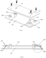
- Figs. 1 to 4 illustrate a display system 100, particularly components of a display system 100 on which a display module (not shown) is mounted.
- the display system 100 includes a first component 102 and a second component 104.
- the display panel may be mounted on the first component 102 and the second component 104 may be mounted on the vehicle (not shown).
- the first component 102 and the second component 104 may include a number of joining locations 106, 108 at which the components 102, 104 are joined. Due to manufacturing defects and/or selection of material of the components 102, 104, the joining locations may have multiple planes, which affects flatness of the components 102, 104 on which the display panel is mounted. Therefore, a tolerance compensation is required for maintaining the flatness of the components 102, 104 such that the display panel may be mounted on the same plane. The tolerance compensation ensures clear viewing on the display panel since the flatness is maintained. Due to this, the vibration effect on the display panel may also be minimized. It is to be understood that the tolerance compensation system 200 may not be limited to a display system of a vehicle and may be used to join any two or more components which require tolerance compensation.
- the display system 100 may comprises four joining locations 106, 108. Three of the joining locations 106 may lie on the same plane, and the fourth joining location 108 may not lie on the same plane as the other three joining locations 106. Therefore, the tolerance compensation system 200 is required for obtaining the flatness of the second component 104 with respect to the first component 102.
- the tolerance compensation system 200 may be used at one or more joining points of the components 102, 104, where a tolerance is required to be provided between the first component 102 and the second component 104.
- Fig. 3 is an exploded view of the display system 100.
- the first component 102 includes four joining faces 106a and 108a.
- the joining faces 106a may lie on the same plane such that the second component 104 abuts the joining faces 106a of the first component 102.
- the joining face 108a may not lie on the same plane as the joining faces 106a, and hence the tolerance compensation system 200 is used at the joining location 108.
- the joining face 106a directly touches the second component 104, and the joining face 108a may be spaced apart from the second component 104. Therefore, the tolerance compensation 200 may be used for maintaining the flatness of the second component 104 and to compensate the gap between the joining face 108a and the second component 104.
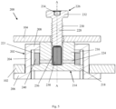
- Fig. 5 illustrates the sectional view along a section line B-B of the tolerance compensation system 200 of Fig. 2 .
- the tolerance compensation system 200 comprises a compensator housing 202.
- the compensator housing 202 is configured to be fixed on the first component 102.
- the tolerance compensation system 200 further comprises a swimming bolt 214 fitted into the compensator housing 202.
- the tolerance compensation system 200 further comprises a glue tank 236 filled with glue 238.
- the glue tank 236 is provided inside the swimming bolt 214.
- the glue 238 is directly provided inside the swimming bolt 214.
- the tolerance compensation system 200 further comprises a screw 226 for fixing the second component 104 with the swimming bolt 214.
- the screw 226 is configured to burst the glue tank 236 and/or compress the glue 23 when tightened. As a result, the glue flows out of the glue tank 236 to join the compensator housing 202 and the swimming bolt 214.
- Fig. 5 shows a state of the tolerance compensation system 200 when the screw 226 is not tight
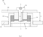
- Fig. 6 illustrates the tolerance compensation when the screw 226 is tightened and the glue tank 236 is burst and the glue 238 is in contact with the compensator housing 202 and the swimming bolt 214.
- the tolerance compensation system 200 will now be described in more detail.
- the compensator housing 202 comprises a wall 204, a stub end 206 and a bolt end 208.
- the stub end 206 of the compensator housing 202 is configured to abut the first component 102.
- the wall 204 of the compensator housing 202 may be cylindrical.
- the first component 102 has a hole of diameter D1 (shown in Fig. 10 ) and the wall 204 of the compensator housing 202 has a diameter which is configured to tightly fit into the hole of the first component 102 forming a seal between the first component 102 and the compensator housing 202.
- the wall 204 of the compensator housing may be a non-cylindrical wall such a square or hexagonal shaped wall, and the hole of the first component may be shaped based on the shape of the wall 204 of the compensator housing 202.
- the bolt end 208 of the compensator housing 202 has a hole 210 (also shown in Fig. 10 ) through which the swimming bolt 214 is inserted.
- the wall 204 of the compensator housing 202 has at least one groove 212 (shown in Figs. 7a and 7b ) positioned on the inner side of the wall 204.
- the at least one groove 212 is provided at least partially on the inner side of the wall 204 for restricting the movement between the compensator housing 202 and the swimming bolt 214.
- the swimming bolt 214 comprises a body 216 having an axis A-A and a head portion 218.
- the body 216 of the swimming bolt has a first surface 216a and a second surface 216b.
- the first surface 216a of the body 216 is configured to fit into the hole 210 of the compensator housing 202 forming a seal between the compensator housing 202 and the swimming bolt 214.
- the second surface 216b of the swimming bolt 214 is configured to abut the second component 104.
- the head portion 218 of the swimming bolt 214 is configured to sealably touch the inner portion of the wall 204 of the compensator housing 202.
- the head portion 218 further comprises at least one protrusion 220.
- the at least one protrusion 220 is configured to be inserted inside the at least one groove 212 of the compensator housing 202. This way the rotation between the swimming bolt 214 and the compensator housing 202 about the axis A-A.
- the diameter of the body 216 of the swimming bolt 214 may be less than the diameter of the inner side of the wall 204 of the compensator housing 202 such that a space 221 is enclosed between the swimming bolt 214 and the compensator housing 202.
- the swimming bolt 214 further comprises a threaded hole 222 along the axis A-A from the second surface 216b upto a depth D (shown in Fig. 6 ).
- the glue tank 236 is placed inside the threaded hole 222 of the swimming bolt 214.
- the glue tank 236 is filled with the glue 238.
- the glue 238 is directly placed inside the threaded hole 222 of the swimming bolt 214 without using the glue tank 236.
- the swimming bolt 214 further comprises at least one channel 224 configured between the threaded hole and the first surface 216a.
- the at least one channel 224 is configured to connect the threaded hole 222 of the swimming bolt 214 and the space 221 between the swimming bolt 214 and the compensator housing 202.
- the threaded hole 222 of the swimming bolt 214 is configured to receive the screw 226.
- the screw 226 comprises a body 228 having length L and a head 232.
- the body 228 of the screw 236 has external threads 230 which is configured to be tightened inside the threaded hole 222 of the swimming bolt 214.
- the second component 104 of the display system 100 is configured between the swimming bolt 214 and the head 232 of the screw 226.
- the head 232 of the screw 226 is configured to fix the second component 104 with the swimming bolt 214.
- the head 232 further comprises a tool groove 234 for inserting a screwing tool (not shown) for tightening the screw 226 inside the threaded hole 222 of the swimming bolt 214.
- the screw 226 is configured to move towards the glue tank 236 when tightened and the glue tank 236 gets compressed.
- the screw 226, when tightened pushes the glue 238 to fill the space 221 between the swimming bolt 214 and the compensator housing 202.
- the glue tank 236 is configured to burst on compression, and the glue 238 is configured to flow through the at least one channel 224 to reach the space 221 between the swimming bolt 214 and the compensator housing 202.
- the glue 238 is cured after reaching the space 221 to create an adhesive joint between the swimming bolt 214 and the compensator housing 202.
- the glue 238 may be one material glue, that is to say, the glue 238 may not require an additional material for providing the adhesive property.
- the glue 238 may have a first glue material and a second glue material 240.
- the first glue material may be stored in the glue tank 236 and the second glue material 240 may be stored in the space 221, such that when the first glue material comes in contact with the second glue material 240, the combination of the first glue material and the second glue material 240 provides the adhesive property to the glue 238.
- the second glue material 240 may enhance curing time for adhesive bond between the compensator housing 202 and the swimming bolt 214.
- the second glue material 240 may be a glue accelerator which may not provide adhesive property to the glue but may enhance the curing time for the adhesive bond.
- Fig. 6 which illustrates the first component 102 and the second component 104 with tolerance compensation system 200 in fully assembled state.
- a gap G is maintained between the first component 102 and the second component 104 for compensating tolerance between the first component 102 and the second component 104.
- the gap G may be adjusted based on the required tolerance between the first component 102 and the second component 104.
- the gap G may be varied for obtaining the flatness.
- a tolerance compensation system 200 according to the present disclosure may be used, each tolerance compensation system 200 may have different values of the gap G.
- the movement of the first component (102) and the second component (104) may be restricted by fixing the first component (102) and the second component (104) on a supporting jig (not shown).
- the movement of the first component 102 and the second component 104 may be restricted by providing additional design features in the first component 102 and the second component 104, shown in Fig. 3 .
- the first component 102 includes at least one centering part 109 and the second component 104 includes at least one centering hole 110.
- the at least one centering part 109 is configured to be inserted into the at least one centering hole 110 of the second component 104 for restricting the movement of the first component 102 and the second component 104.
- the at least one centering part 109 includes two centering parts 109, and the at least one centering hole 110 includes one circular hole and one slotted hole.
- the additional design feature (not shown) of the first component 102 and the second component 104 may include ribs for supporting the first component 102 and the second component 104 during assembly.
- the present disclosure also refers to a method for joining the first component 102 and the second component 104 with tolerance compensation.
- Fig. 8 which illustrates an exploded view of the tolerance compensation system 200, will now be used to describe the method.
- the method comprises a step of disposing the compensator housing 202 on the first component 102.
- the method further comprises a step of inserting the swimming bolt 214 inside the hole 210 of the compensator housing 202.
- the method further comprises a step of placing the second component 104 on the second surface 216b of the swimming bolt 214, wherein the glue tank 236 having the glue 238 or directly the glue 238 without the glue tank is placed inside the threaded hole 222 of the swimming bolt 214.
- the method further comprise a step of inserting the screw 226 having external threads 230 and length (L) inside the threaded hole 222 of the swimming bolt 214 and tightening the screw 226 by using the screwing tool, wherein the screwing tool is inserted in the groove 234 of the screw 226.
- the method further comprises a step of compressing and bursting the glue tank 236 by the screw 226 when the screw 226 is tightened inside the threaded hole 222 of the swimming bolt 214.
- the method further comprises a step of allowing the glue 238 to flow through the channel 224 configured within the swimming bolt 214 to fill the space 221 between the swimming bolt 214 and the compensator housing 202.
- the method further comprises a step of curing the glue 238 to obtain the adhesive joint between the swimming bolt 214 and the compensator housing 202.
- the method further comprises a step of providing a supporting jig (not shown) for providing rigidity to the first component 102, the second component 104, the compensator housing 202 and the swimming bolt 214 during the curing step.
- the supporting jig may be provided to rigidly support the system and ease the curing step and to obtain a desired value of the gap G between the first component 102 and the second component 104.
Landscapes
- Engineering & Computer Science (AREA)
- Mechanical Engineering (AREA)
- Chemical & Material Sciences (AREA)
- Combustion & Propulsion (AREA)
- Transportation (AREA)
- General Engineering & Computer Science (AREA)
- Standing Axle, Rod, Or Tube Structures Coupled By Welding, Adhesion, Or Deposition (AREA)
Priority Applications (1)
| Application Number | Priority Date | Filing Date | Title |
|---|---|---|---|
| EP23200877.1A EP4530482A1 (de) | 2023-09-29 | 2023-09-29 | Toleranzausgleichssystem und verfahren zum verbinden eines ersten bauteils und eines zweiten bauteils |
Applications Claiming Priority (1)
| Application Number | Priority Date | Filing Date | Title |
|---|---|---|---|
| EP23200877.1A EP4530482A1 (de) | 2023-09-29 | 2023-09-29 | Toleranzausgleichssystem und verfahren zum verbinden eines ersten bauteils und eines zweiten bauteils |
Publications (1)
| Publication Number | Publication Date |
|---|---|
| EP4530482A1 true EP4530482A1 (de) | 2025-04-02 |
Family
ID=88241248
Family Applications (1)
| Application Number | Title | Priority Date | Filing Date |
|---|---|---|---|
| EP23200877.1A Withdrawn EP4530482A1 (de) | 2023-09-29 | 2023-09-29 | Toleranzausgleichssystem und verfahren zum verbinden eines ersten bauteils und eines zweiten bauteils |
Country Status (1)
| Country | Link |
|---|---|
| EP (1) | EP4530482A1 (de) |
Cited By (1)
| Publication number | Priority date | Publication date | Assignee | Title |
|---|---|---|---|---|
| US20250203789A1 (en) * | 2023-12-19 | 2025-06-19 | Ford Global Technologies, Llc | Device with tolerance absorbing removable joint and method of assembling a device with a tolerance absorbing removable joint |
Citations (4)
| Publication number | Priority date | Publication date | Assignee | Title |
|---|---|---|---|---|
| CN1576614A (zh) * | 2003-07-29 | 2005-02-09 | 株式会社青山制作所 | 紧固装置 |
| EP1304489B1 (de) | 2001-10-18 | 2005-08-10 | Böllhoff GmbH | Toleranzausgleichsanordnung |
| US20150291224A1 (en) * | 2014-04-14 | 2015-10-15 | Ford Global Technologies, Llc | Compensator assembly for a vehicle frame |
| KR102385282B1 (ko) * | 2021-06-22 | 2022-04-08 | 강재성 | 공차 보정 시스템 |
-
2023
- 2023-09-29 EP EP23200877.1A patent/EP4530482A1/de not_active Withdrawn
Patent Citations (4)
| Publication number | Priority date | Publication date | Assignee | Title |
|---|---|---|---|---|
| EP1304489B1 (de) | 2001-10-18 | 2005-08-10 | Böllhoff GmbH | Toleranzausgleichsanordnung |
| CN1576614A (zh) * | 2003-07-29 | 2005-02-09 | 株式会社青山制作所 | 紧固装置 |
| US20150291224A1 (en) * | 2014-04-14 | 2015-10-15 | Ford Global Technologies, Llc | Compensator assembly for a vehicle frame |
| KR102385282B1 (ko) * | 2021-06-22 | 2022-04-08 | 강재성 | 공차 보정 시스템 |
Cited By (2)
| Publication number | Priority date | Publication date | Assignee | Title |
|---|---|---|---|---|
| US20250203789A1 (en) * | 2023-12-19 | 2025-06-19 | Ford Global Technologies, Llc | Device with tolerance absorbing removable joint and method of assembling a device with a tolerance absorbing removable joint |
| US12471229B2 (en) * | 2023-12-19 | 2025-11-11 | Ford Global Technologies, Llc | Device with tolerance absorbing removable joint and method of assembling a device with a tolerance absorbing removable joint |
Similar Documents
| Publication | Publication Date | Title |
|---|---|---|
| JP3464523B2 (ja) | 積層ガラスへの保持部材または固定部材の螺子止め固着 | |
| EP4530482A1 (de) | Toleranzausgleichssystem und verfahren zum verbinden eines ersten bauteils und eines zweiten bauteils | |
| EP2135796B1 (de) | Getriebe-Antriebseinheit sowie einem Verfahren zur Herstellung einer solchen | |
| JP4723604B2 (ja) | 木製部材の制震機能付接合構造及び木製部材用制震機能付接合装置 | |
| JP2007518937A (ja) | コネクタ | |
| CN1042510C (zh) | 汽车制动助力器安装装置 | |
| KR100235366B1 (ko) | 연료 압력 센서를 위한 밀봉 유닛 | |
| JP2003532820A (ja) | 内燃機関用の燃料噴射系のための接続管片、及び予負荷されて溶接された接続管片を備えたケーシング、特に燃料高圧アキュムレータ | |
| JP3949123B2 (ja) | 航空機用モジュール取付装置 | |
| CN115803535A (zh) | 偏移连接装置 | |
| JP4021897B2 (ja) | チューブ状第1コンポーネントを第2コンポーネントに接続するための配置構造及びこの種の配置構造を製造するための方法 | |
| JP2007309513A (ja) | 固定構造および固定方法 | |
| JP7831545B2 (ja) | 樹脂チューブ接続装置 | |
| JPH06185518A (ja) | 板材へのナット取付構造および方法 | |
| US7246965B2 (en) | Method of assembling a link to a support, and a vibration-damping device manufactured by said method | |
| JP3967862B2 (ja) | 気体ダクトの保形装置 | |
| JPH08209882A (ja) | 手摺用連結金具 | |
| JP7033046B2 (ja) | 防振ゴム振れ止め機構の組立方法 | |
| EP4074988A1 (de) | Unverlierbarer verbinder und verfahren zum verbinden | |
| JP2652287B2 (ja) | セパレータ継ぎ足し用金具 | |
| CN214412456U (zh) | 面密封结构及驱动电机 | |
| KR20050101406A (ko) | 이중 고정력 형성 타입 팝 너트 | |
| US6412367B1 (en) | Mounting structure for a hydrostatic unit | |
| CN208792509U (zh) | 一种管柱拼接结构 | |
| JPH07269539A (ja) | 締結部材 |
Legal Events
| Date | Code | Title | Description |
|---|---|---|---|
| PUAI | Public reference made under article 153(3) epc to a published international application that has entered the european phase |
Free format text: ORIGINAL CODE: 0009012 |
|
| STAA | Information on the status of an ep patent application or granted ep patent |
Free format text: STATUS: THE APPLICATION HAS BEEN PUBLISHED |
|
| AK | Designated contracting states |
Kind code of ref document: A1 Designated state(s): AL AT BE BG CH CY CZ DE DK EE ES FI FR GB GR HR HU IE IS IT LI LT LU LV MC ME MK MT NL NO PL PT RO RS SE SI SK SM TR |
|
| STAA | Information on the status of an ep patent application or granted ep patent |
Free format text: STATUS: THE APPLICATION HAS BEEN WITHDRAWN |
|
| 18W | Application withdrawn |
Effective date: 20250521 |