EP4530481A1 - Anpassbare befestigungsschnittstelle für einen flugzeugkabinenboden - Google Patents
Anpassbare befestigungsschnittstelle für einen flugzeugkabinenboden Download PDFInfo
- Publication number
- EP4530481A1 EP4530481A1 EP23200657.7A EP23200657A EP4530481A1 EP 4530481 A1 EP4530481 A1 EP 4530481A1 EP 23200657 A EP23200657 A EP 23200657A EP 4530481 A1 EP4530481 A1 EP 4530481A1
- Authority
- EP
- European Patent Office
- Prior art keywords
- floor
- interface
- connection
- studs
- fixation
- Prior art date
- Legal status (The legal status is an assumption and is not a legal conclusion. Google has not performed a legal analysis and makes no representation as to the accuracy of the status listed.)
- Pending
Links
Images




Classifications
-
- B—PERFORMING OPERATIONS; TRANSPORTING
- B60—VEHICLES IN GENERAL
- B60N—SEATS SPECIALLY ADAPTED FOR VEHICLES; VEHICLE PASSENGER ACCOMMODATION NOT OTHERWISE PROVIDED FOR
- B60N2/00—Seats specially adapted for vehicles; Arrangement or mounting of seats in vehicles
- B60N2/005—Arrangement or mounting of seats in vehicles, e.g. dismountable auxiliary seats
- B60N2/015—Attaching seats directly to vehicle chassis
- B60N2/01508—Attaching seats directly to vehicle chassis using quick release attachments
- B60N2/01516—Attaching seats directly to vehicle chassis using quick release attachments with locking mechanisms
-
- B—PERFORMING OPERATIONS; TRANSPORTING
- B64—AIRCRAFT; AVIATION; COSMONAUTICS
- B64C—AEROPLANES; HELICOPTERS
- B64C1/00—Fuselages; Constructional features common to fuselages, wings, stabilising surfaces or the like
- B64C1/18—Floors
-
- B—PERFORMING OPERATIONS; TRANSPORTING
- B60—VEHICLES IN GENERAL
- B60N—SEATS SPECIALLY ADAPTED FOR VEHICLES; VEHICLE PASSENGER ACCOMMODATION NOT OTHERWISE PROVIDED FOR
- B60N2/00—Seats specially adapted for vehicles; Arrangement or mounting of seats in vehicles
- B60N2/02—Seats specially adapted for vehicles; Arrangement or mounting of seats in vehicles the seat or part thereof being movable, e.g. adjustable
- B60N2/0224—Non-manual adjustments, e.g. with electrical operation
- B60N2/0244—Non-manual adjustments, e.g. with electrical operation with logic circuits
- B60N2/0264—Non-manual adjustments, e.g. with electrical operation with logic circuits characterised by the type of electrical connection, e.g. wiring, plugs or USB
-
- B—PERFORMING OPERATIONS; TRANSPORTING
- B64—AIRCRAFT; AVIATION; COSMONAUTICS
- B64C—AEROPLANES; HELICOPTERS
- B64C1/00—Fuselages; Constructional features common to fuselages, wings, stabilising surfaces or the like
- B64C1/18—Floors
- B64C1/20—Floors specially adapted for freight
-
- B—PERFORMING OPERATIONS; TRANSPORTING
- B64—AIRCRAFT; AVIATION; COSMONAUTICS
- B64D—EQUIPMENT FOR FITTING IN OR TO AIRCRAFT; FLIGHT SUITS; PARACHUTES; ARRANGEMENT OR MOUNTING OF POWER PLANTS OR PROPULSION TRANSMISSIONS IN AIRCRAFT
- B64D11/00—Passenger or crew accommodation; Flight-deck installations not otherwise provided for
- B64D11/06—Arrangements of seats, or adaptations or details specially adapted for aircraft seats
- B64D11/0696—Means for fastening seats to floors, e.g. to floor rails
-
- F—MECHANICAL ENGINEERING; LIGHTING; HEATING; WEAPONS; BLASTING
- F16—ENGINEERING ELEMENTS AND UNITS; GENERAL MEASURES FOR PRODUCING AND MAINTAINING EFFECTIVE FUNCTIONING OF MACHINES OR INSTALLATIONS; THERMAL INSULATION IN GENERAL
- F16B—DEVICES FOR FASTENING OR SECURING CONSTRUCTIONAL ELEMENTS OR MACHINE PARTS TOGETHER, e.g. NAILS, BOLTS, CIRCLIPS, CLAMPS, CLIPS OR WEDGES; JOINTS OR JOINTING
- F16B33/00—Features common to bolt and nut
- F16B33/004—Sealing; Insulation
-
- F—MECHANICAL ENGINEERING; LIGHTING; HEATING; WEAPONS; BLASTING
- F16—ENGINEERING ELEMENTS AND UNITS; GENERAL MEASURES FOR PRODUCING AND MAINTAINING EFFECTIVE FUNCTIONING OF MACHINES OR INSTALLATIONS; THERMAL INSULATION IN GENERAL
- F16B—DEVICES FOR FASTENING OR SECURING CONSTRUCTIONAL ELEMENTS OR MACHINE PARTS TOGETHER, e.g. NAILS, BOLTS, CIRCLIPS, CLAMPS, CLIPS OR WEDGES; JOINTS OR JOINTING
- F16B35/00—Screw-bolts; Stay-bolts; Screw-threaded studs; Screws; Set screws
- F16B35/04—Screw-bolts; Stay-bolts; Screw-threaded studs; Screws; Set screws with specially-shaped head or shaft in order to fix the bolt on or in an object
- F16B35/041—Specially-shaped shafts
-
- F—MECHANICAL ENGINEERING; LIGHTING; HEATING; WEAPONS; BLASTING
- F16—ENGINEERING ELEMENTS AND UNITS; GENERAL MEASURES FOR PRODUCING AND MAINTAINING EFFECTIVE FUNCTIONING OF MACHINES OR INSTALLATIONS; THERMAL INSULATION IN GENERAL
- F16B—DEVICES FOR FASTENING OR SECURING CONSTRUCTIONAL ELEMENTS OR MACHINE PARTS TOGETHER, e.g. NAILS, BOLTS, CIRCLIPS, CLAMPS, CLIPS OR WEDGES; JOINTS OR JOINTING
- F16B5/00—Joining sheets or plates, e.g. panels, to one another or to strips or bars parallel to them
- F16B5/02—Joining sheets or plates, e.g. panels, to one another or to strips or bars parallel to them by means of fastening members using screw-thread
-
- F—MECHANICAL ENGINEERING; LIGHTING; HEATING; WEAPONS; BLASTING
- F16—ENGINEERING ELEMENTS AND UNITS; GENERAL MEASURES FOR PRODUCING AND MAINTAINING EFFECTIVE FUNCTIONING OF MACHINES OR INSTALLATIONS; THERMAL INSULATION IN GENERAL
- F16B—DEVICES FOR FASTENING OR SECURING CONSTRUCTIONAL ELEMENTS OR MACHINE PARTS TOGETHER, e.g. NAILS, BOLTS, CIRCLIPS, CLAMPS, CLIPS OR WEDGES; JOINTS OR JOINTING
- F16B5/00—Joining sheets or plates, e.g. panels, to one another or to strips or bars parallel to them
- F16B5/06—Joining sheets or plates, e.g. panels, to one another or to strips or bars parallel to them by means of clamps or clips
- F16B5/0607—Joining sheets or plates, e.g. panels, to one another or to strips or bars parallel to them by means of clamps or clips joining sheets or plates to each other
- F16B5/0621—Joining sheets or plates, e.g. panels, to one another or to strips or bars parallel to them by means of clamps or clips joining sheets or plates to each other in parallel relationship
- F16B5/0635—Joining sheets or plates, e.g. panels, to one another or to strips or bars parallel to them by means of clamps or clips joining sheets or plates to each other in parallel relationship fastened over the edges of the sheets or plates
-
- F—MECHANICAL ENGINEERING; LIGHTING; HEATING; WEAPONS; BLASTING
- F16—ENGINEERING ELEMENTS AND UNITS; GENERAL MEASURES FOR PRODUCING AND MAINTAINING EFFECTIVE FUNCTIONING OF MACHINES OR INSTALLATIONS; THERMAL INSULATION IN GENERAL
- F16B—DEVICES FOR FASTENING OR SECURING CONSTRUCTIONAL ELEMENTS OR MACHINE PARTS TOGETHER, e.g. NAILS, BOLTS, CIRCLIPS, CLAMPS, CLIPS OR WEDGES; JOINTS OR JOINTING
- F16B21/00—Means for preventing relative axial movement of a pin, spigot, shaft or the like and a member surrounding it; Stud-and-socket releasable fastenings
- F16B21/02—Releasable fastening devices locking by rotation
-
- F—MECHANICAL ENGINEERING; LIGHTING; HEATING; WEAPONS; BLASTING
- F16—ENGINEERING ELEMENTS AND UNITS; GENERAL MEASURES FOR PRODUCING AND MAINTAINING EFFECTIVE FUNCTIONING OF MACHINES OR INSTALLATIONS; THERMAL INSULATION IN GENERAL
- F16B—DEVICES FOR FASTENING OR SECURING CONSTRUCTIONAL ELEMENTS OR MACHINE PARTS TOGETHER, e.g. NAILS, BOLTS, CIRCLIPS, CLAMPS, CLIPS OR WEDGES; JOINTS OR JOINTING
- F16B2200/00—Constructional details of connections not covered for in other groups of this subclass
- F16B2200/93—Fastener comprising feature for establishing a good electrical connection, e.g. electrostatic discharge or insulation feature
-
- F—MECHANICAL ENGINEERING; LIGHTING; HEATING; WEAPONS; BLASTING
- F16—ENGINEERING ELEMENTS AND UNITS; GENERAL MEASURES FOR PRODUCING AND MAINTAINING EFFECTIVE FUNCTIONING OF MACHINES OR INSTALLATIONS; THERMAL INSULATION IN GENERAL
- F16B—DEVICES FOR FASTENING OR SECURING CONSTRUCTIONAL ELEMENTS OR MACHINE PARTS TOGETHER, e.g. NAILS, BOLTS, CIRCLIPS, CLAMPS, CLIPS OR WEDGES; JOINTS OR JOINTING
- F16B2200/00—Constructional details of connections not covered for in other groups of this subclass
- F16B2200/95—Constructional details of connections not covered for in other groups of this subclass with markings, colours, indicators or the like
Definitions
- the present invention relates to fixations in a floor area of an aircraft, and relates in particular to an adaptable fixation interface for an aircraft cabin floor, to an aircraft floor mounting system, to an aircraft floor arrangement with an adaptable fixation rail, to an aircraft and to a method for providing a fixation interface for an aircraft cabin floor.
- Fixations in the floor area of an aircraft cabin are provided for mounting cabin interior equipment like passenger seats.
- An example for such fixations are so-called seat rails.
- Longitudinal profiles with a defined cross-section are provided that allow clamping of a seat leg fitting along the rail.
- the upper part of the seat rail provides recesses or protrusions for a form-fitting engagement of the fitting. Since the set rails may be provided throughout the cabin space, their upper profile should be flush with adjacent floor panels to avoid obstacles for passengers in areas where the seat rails are not used for fixation of seats. While the seat rails should be light, still allowing the releasable mount of equipment like passenger seats in various locations along the rail, an increasing demand exists regarding the sealing capacity along the seat rails.
- an adaptable fixation interface for an aircraft cabin floor comprises a plurality of connection studs.
- the connection studs comprise a mounting foot region and a connection head region.
- the mounting foot region is configured to be inserted into one of a plurality of interface points in a floor arrangement.
- the connection head region is configured to be engaged by a fitting of an equipment to be fixed to the floor arrangement.
- the connection studs are configured to be releasably connected to adjacent interface points in a floor arrangement to provide a longitudinally extending fixation interface segment for mounting of equipment.
- connection studs can be adapted to the actual demand, which allows weight savings, while still providing the option of improved sealing.
- the plurality connection studs are configured to form an adaptable rail-like fixation segment when the connection studs are mounted to a floor support structure.
- the rail-like fixation segment provides a connecting profile for mounting equipment comprising at least one of the group of seats and monuments.
- the mounting foot region comprises at least one lateral protrusion for a form-fitting engagement with radial wall segments of a floor arrangement interface point.
- the connection head region comprises a flange-like protrusion for a form-fit clamping of an equipment fitting configured to be resting on an upper end face provided by the connection head region.
- the flange-like protrusion of the connection head region is having two opposite complementary abutment edges that are configured to provide a continuous fixation profile when several of the connection studs are mounted to a support beam in an adjacent manner.
- the flange-like protrusion of the connection head region is having two further opposite edges transverse to the abutment edges.
- the further opposite edges are configured to provide lateral projections of the continuous fixation profile when several of the connection studs are mounted to the support beam in an adjacent manner.
- connection head region also provides lateral indentations alternately arranged with the lateral projections when several of the connection studs are mounted to the support beam in an adjacent manner.
- a fitting for mounting equipment to the fixation interface segment of the connection studs.
- the fitting comprises at least two fitting engaging portions to engage with at least two flange-like protrusions of the connection studs.
- the fitting comprises at least two connection shoes with a slot like recess configured to slidingly engage with the connection head region.
- the connection shoes are movably attached to a body structure of the fitting such to be rotated to provide a locking against a release of the connection shoes from the connection head region.
- a visual locking indicator is provided.
- connection studs are configured as an electric interface providing at least one conducting path for transmitting electric energy.
- an aircraft floor mounting system comprising at least one adaptable fixation interface with a plurality of connection studs according to one of the examples above and at least one longitudinally extending clamping profile.
- the clamping profile comprises at least one outer section for holding an edge of at least one floor panel and a central recessed section for attaching the clamping profile to a floor support beam of an aircraft cabin.
- the connection studs are configured to be provided along the central section in the mounted state.
- an aircraft floor arrangement with an adaptable fixation rail comprises at least one floor support, a plurality of interface points provided on an upper side along at least a part of the floor support and at least one adaptable fixation interface with a plurality of connection studs according to one of the examples above.
- the interface points are configured to receive the mounting foot region of one of the connection studs.
- the floor arrangement further comprises at least one floor panel resting on the floor support and at least one clamping profile.
- the clamping profile is configured to hold an upper lateral edge of the floor panel in a clamping manner.
- the clamping profile is configured to be attached to the floor support by at least one of the group comprising the interface points and the connection studs.
- an aircraft comprising a fuselage and a wing arrangement attached to the fuselage.
- An aircraft cabin is provided within the fuselage, the cabin comprising a cabin floor.
- the cabin floor comprises an aircraft floor mounting system according to one of the examples above.
- the cabin floor is provided as a floor arrangement according to one of the examples above.
- a method for providing fixation interface for an aircraft cabin floor comprises the following steps:
- fixation or arresting studs also referred to as connection studs
- connection studs are provided for assembly of a floor structure.
- the fixation or arresting studs are also used for a form-fit clamping of floor panels with a stainless clamping layer.
- fixation or arresting studs are provided as a cabin interface for mounting equipment like seats or monuments to the floor construction.
- a floor connection interface comprises stainless surfaces towards the cabin space, while allowing load transfer to a non-stainless support structure, such as an aluminum support structure.
- the fixation interface is an interface for mounting equipment to a floor in a cabin area.
- the fixation interface can thus also be referred to as cabin interface.
- the fixation interface is provided as an insertable and thus releasable bolt or stud.
- the bolt or stud has a sort of mushroom head for engagement by fittings for mounting equipment.
- a form-fit clamping of seats and panels is provided with a rather low-cost continuous stainless profile on an also low-cost aluminum hat profile.
- connection studs The advantage of single components in form of the connection studs and the combination of only a few of them to create an interface provides the opportunity of a flexible layout configuration for an operator of the aircraft. Weight is only introduced where it is needed.
- the rail-like fixation segment is provided by a plurality of individual, i.e. separate parts. This allows to provide an adapted fixation rail arrangement, since the rail-like fixation segment can only be provided where necessary. This contributes to weight and also cost savings.
- Fig. 1a schematically shows an example of an adaptable fixation interface 10 for an aircraft cabin floor in a top view.
- Fig. 1b schematically shows the fixation interface 10 of Fig. 1a in a side view.
- the adaptable fixation interface 10 comprises a plurality of connection studs 12.
- the connection studs 12 comprise a mounting foot region 14 and a connection head region 16, as indicated in Fig. 1a .
- the mounting foot region 14 is configured to be inserted into one of a plurality of interface points in a floor arrangement (see also Fig. 2 ).
- the connection head region 16 is configured to be engaged by a fitting of an equipment to be fixed to the floor arrangement.
- the connection studs 12 are configured to be releasably connected to adjacent interface points in a floor arrangement to provide a longitudinally extending fixation interface segment for mounting of equipment.
- the interface points in a floor arrangement can be provided as floor arrangement interface points 18, see also Fig. 2 .
- the interface points can also be provided for fulfilling further tasks, such as being interface points for connection of corrugated floor panels to floor support structures.
- fixation interface relates to an arrangement that provides a mechanical interaction for mounting parts to the cabin floor.
- the parts can be releasably fixed by the interface.
- the fixation interface can also be referred to as fixation arrangement, mounting interface, mounting arrangement, connecting interface or connecting arrangement.
- the term "adaptable” relates to the option to provide the engagement sections of the connection studs only where needed.
- aircraft cabin floor relates to a floor within the aircraft cabin, e.g. delimiting the cabin area from a cargo area arranged below the cabin area within the fuselage of an aircraft.
- connection studs relates to pin-like elements that can be inserted into recesses of a floor support for acting as connecting interface.
- the studs can also be referred to as bolts or pins.
- the connection studs may therefore have an insertion or mounting direction. In an option, the insertion or mounting direction is aligned with a Z-direction in an aircraft when being mounted, i.e. assembled.
- mounting foot region relates to the lower end of the connection stud that is connected the floor support structure.
- connection head region relates to the upper end of the connection stud that is provided for being engaged by the equipment to be fixed by the connection stud.
- adjacent relates to neighboring studs, i.e. the next stud.
- the adjacent studs contact each other.
- the adjacent studs are provided displaced to each other, i.e. with a predetermined distance.
- interface points relates to connecting portions or segments arranged for acting as a mechanical interface for the studs.
- the interface points may be added to a floor support structure or may be provided in an integrated manner.
- fixation interface segment relates to an interface provided by the several connection studs that is capable of receiving a fitting or the like for fixing equipment.
- segment indicates that along the linear arrangement of the interface points, also further segments can be provided.
- the segment forms a sort of rail segment.
- Several segments thus form a virtual rail with rail segments, i.e. rail sections, and interrupted rail segments, i.e. interrupted rail sections.
- equipment relates to seats, monuments, lavatories, galleys and other parts provided within the cabin space.
- the adaptable interface can also be referred to as adaptable seat fixation interface or adaptable monument fixation interface.
- the fixation or arresting studs also provide a sealing, e.g. a sealing arrangement, device between the cabin space and a lower structure,
- a sealing e.g. a sealing arrangement
- the fixation or arresting studs are made from stainless, i.e. non-corrosive material.
- connection studs are configured to form a rail.
- the supporting floor structure so-to-speak plays the role of providing a body structure of the rail, while the connection studs provide the engagement profile section.
- Fig. 3a shows another example of an adaptable fixation interface 10 for an aircraft cabin floor in a top view.
- connection head region 16 comprises a flange-like protrusion 30 for a form-fit clamping of an equipment fitting configured to be resting on an upper end face 32 provided by the connection head region 16.
- lateral protrusion relates to a part or portion that extends transverse to an insertion direction for engaging and thus holding of the connection stud within the support structure.
- flange-like protrusion relates to a part or portion that extends transverse to the insertion direction and that allows an engagement by a form-fitting counterpart of a fitting or the like.
- upper end face relates to the part of the connection stud that faces upwards in a mounted state, i.e. that faces the equipment to be mounted.
- a quick release fitting for the fixation that creates the seat interface is provided.
- the mounting foot region is provided as a quick release connector that comprises retractable protrusions at its distal end portion.
- the mounting foot region is provided with an outer thread for engagement with an inner thread of the floor arrangement interface point.
- connection head region is provided as a circular flange that also provides the upper end face.
- the flange-like protrusion 30 of the connection head region 16 is having two opposite complementary abutment edges 34 that are configured to provide a continuous fixation profile when several of the connection studs 12 are mounted to a support beam in an adjacent manner.
- the flange-like protrusion 30 of the connection head region 16 is having two further opposite edges 36 transverse to the abutment edges 34.
- the further opposite edges 36 are configured to provide lateral projections of the continuous fixation profile when several of the connection studs 12 are mounted to the support beam in an adjacent manner.
- connection head region 16 also provides lateral indentations 38 alternately arranged with the lateral projections when several of the connection studs 12 are mounted to the support beam in an adjacent manner.
- connection head region is provided as a cross-shaped flange with four rectangular flange sections projecting along two axis that are perpendicular to each other and perpendicular to a stud insertion direction.
- a fitting 40 is provided for mounting equipment to the fixation interface segment of the connection studs 12.
- the fitting 40 comprises at least two fitting engaging portions 42 to engage with at least two flange-like protrusions of the connection studs 12.
- the fitting 40 comprises at least two connection shoes 44 with a slot like recess 46 configured to slidingly engage with the connection head region; the connection shoes 44 are movably attached to a body structure of the fitting such to be rotated to provide a locking against a release of the connection shoes 44 from the connection head region 16.
- a visual locking indicator 48 is provided. This will be explained further below with reference to Figs. 9a-c .
- connection or mounting interface portion provided for fixedly attaching the equipment to the floor support structure.
- connection shoe relates to a portion of the fitting that can partly enclose a profile or shape of the connection head region.
- visual locking indicator relates to an indicator that allows to check and verify the correct locking state by visual inspection.
- connection shoes are mounted to the body structure such that they can be commonly slided into their engaging position.
- connection shoes are individually rotatable, i.e. the rotation is provided for the connection shoes in separate steps.
- connection shoes are commonly rotatable, i.e. the rotation is provided for the connection shoes in one step.
- connection shoes In an option, a counter-rotation is provided for adjacent connection shoes.
- a visual indicator is provided for an alternate rotation motion of at least a part of the connection shoes.
- connection studs 12 are configured as an electric interface providing at least one conducting path for transmitting electric energy.
- connection relates to providing electric connection via the interface.
- conductors are provided by the connection stud itself.
- additional conductors are provided that run through conduits provided by the connection studs.
- the electric interface is providing two or more conducting paths.
- the electric interface is configured for signal transmission. In another example, the electric interface is configured for energy supply. In a further example, the electric interface is configured for signal transmission and energy supply.
- Fig. 2 shows the adaptable fixation interface of Fig. 1 in the context of a transverse cross-section of an aircraft floor mounting system 50 and also in the context of an aircraft floor arrangement 100.
- the aircraft floor mounting system 50 comprises at least one adaptable fixation interface 52 with a plurality of connection studs 12 according to one of the examples above.
- the aircraft floor mounting system 50 also comprises at least one longitudinally extending clamping profile 54.
- the clamping profile 54 comprises at least one outer section 56 for holding an edge of at least one floor panel and a recessed central section 58 for attaching the clamping profile to a floor support of an aircraft cabin.
- the connection studs 12 are configured to be provided along the central section 58 in the mounted state.
- Fig. 2 also shows a second outer section 60 for holding an edge of at least one further floor panel 62.
- the floor panel is provided as a so-called corrugated floor panel having an upper sheet 64, also referred to as upper panel, and a lower sheet 66, also referred to as lower panel, separated by a center zone with a center layer folded in a way that it is connected to the upper sheet 64 and the lower sheet 66 in an alternating manner.
- clamping profile relates to a profile for attaching floor panels by pressing them against a support surface. The floor panels are thus clamped on their edges.
- outer section relates to the lateral part that engages with the panels.
- central recessed section relates to a part forming a concave profile.
- the central section is provided in a lengthwise direction of the longitudinal cover.
- the central recessed section allows the arrangement of the connection studs within the central recessed section. In an option, the mounted connection studs do not reach over the lateral parts of the clamping profile.
- the clamping profile 54 is configured to be attached to a floor support beam 70 by at least one of the group comprising the interface points 18 and the connection studs 12.
- the floor panels 62 are resting on the floor support beam 70.
- the clamping profile is made from a noncorroding material.
- the clamping profile is made from a stainless steel sheet.
- the clamping profile is made from a sheet made from titanium.
- the floor panels are provided as corrugated profiles, i.e. corrugated panels.
- Fig. 2 shows the adaptable fixation interface 10 in the context of the aircraft floor arrangement 100 with the adaptable fixation rail.
- the aircraft floor arrangement 100 comprises at least one floor support 102 like the floor support beam 70.
- the aircraft floor arrangement 100 also comprises a plurality of interface points 104 provided on an upper side along at least a part of the floor support 102.
- the aircraft floor arrangement 100 further comprises at least one example of the adaptable fixation interface 10 with a plurality of the connection studs 12 according to one of the examples above.
- the interface points 104 are configured to receive the mounting foot region 14 of one of the connection studs 12.
- floor support relates to a floor support structure, such as a beam or carrier.
- the floor support can be provided as a separate beam structure or can be provided by a fuselage support structure.
- the floor support can also be referred to as floor support carrier or floor support profile.
- the floor support can also be referred to as primary structure.
- the floor panel is resting on an upper lateral edge region of the floor support.
- a field of application is the installation of seats and monuments in a cabin of an aircraft.
- the interface points are provided in an inch-wise pattern, i.e. with a determined fixed pitch over the complete length. In an option, the interface points are provided with a varying pattern.
- the interface points are provided as blind nuts 106 with an inner thread aligned with through holes in an upper flange segment of the floor support like the floor support beam.
- the blind nuts 106 provide a bore in which the mounting foot region 14 of one of the connection studs 12 is inserted in an engaging manner with the blind nuts 106.
- blind nuts relates to nut-like members fixed to the base structure.
- the interface points are provided as threaded bores with an inner thread.
- the interface points are provided as drive-in nuts with an inner thread.
- the interface points are provided as milled or casted fixations inner engagement sections.
- the floor arrangement further comprises at least one floor panel 108, like the floor panel 62, resting on the floor support 102.
- the floor arrangement further comprises at least one clamping profile 110, like the clamping profile 54.
- the clamping profile 110 e.g. as the clamping profile 54 mentioned above, is configured to hold an upper lateral edge of the floor panel 108 in a clamping manner.
- the clamping profile 110 is configured to be attached to the floor support 102 by at least one of the group comprising the interface points and the connection studs.
- floor panel relates to panels provided in an aircraft cabin for carrying loads like passengers, luggage or trolleys.
- the floor panels provide a plate-like constructive part for load bearing.
- the floor panels also provide the floor surface like a carpet.
- upper lateral edge relates to a part of the circumferential edge of the panels that faces the clamping profiles.
- the clamping profile is configured to be attached to the floor support beam by at least one of the group comprising the interface points and the connection studs.
- the clamping profile is providing a clamping holding force urging the floor panel against the floor support beam.
- the clamping profile is configured to hold floor panel on both sides of the interface points.
- the clamping profile is made from a noncorroding material.
- connection studs for attaching the clamping profile to the floor support beam, through holes are provided in the clamping profile.
- the connection studs comprise a sealing for sealing off the through holes.
- a sealing insert is provided to seal off the through holes.
- the floor support 102 is made from a corrosive material and the clamping profile 110 is made from a noncorroding material.
- corrosion protection is provided between contacting surfaces of the parts made from noncorroding material and the parts made from corrosive material.
- corrosion protection is provided between contacting surfaces of the floor support beam and the clamping profile.
- the floor support beam is made from aluminum.
- non-corrosive and corrosive relate to substances, in particular liquids, present in a common aircraft cabin when used for usual passenger transport and onboard services.
- Fig. 3a shows a top view of a rail segment formed by three connection studs 12.
- Fig. 3b shows the respective side view or elevation view.
- the connection studs 12 are formed by a bolt 11, e.g. having an outer thread as the mounting foot region 14 for engaging with an inner thread provided in a support structure.
- an upper body 13 is provided in which the bolt 11 is inserted.
- the upper body 13 provides an upper radially extending first collar 15 and a lower radially extending second collar 17.
- the upper body 13 has a recess 19 for inserting the bolt 11.
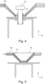
- Fig. 4 shows another example of the aircraft floor arrangement 100.
- a connection stud 12 is inserted in an insert.
- the connection stud 12 is thus connected to the corrosive structure covered by the non-corrosive clamping profile 54.
- a corrosion protection 72 is provided for connecting the connecting stud 12 to the different parts having different metal corrosion related properties.
- the clamping profile 54 is having a central recess 73 for the interface points. Further, at least one floor filler segment 74 is provided conforming with a contour of the central recess. The floor filler segment 74 is configured to be arranged in the central recess e.g. in parts without connection studs 12.
- the floor filler segment 74 comprises a recess on its lower side to be put over segments with mounted connection studs 12.
- the filler segment 74 provides an upper even and flush surface.
- the longitudinal groove is covered by the filling to provide an even cabin floor surface.
- the filler also improves a liquid tightness of the floor construction.
- Fig. 6 shows a further example of the aircraft floor arrangement where a plurality of the connection studs 12 is inserted forming a rail segment for mounting fittings.
- Fig. 7 shows a still further example of an aircraft floor arrangement with a mounted lug interface as an example for the fitting 40.
- the lug interface provides a connection, for example for monuments or passenger seats.
- the lug interface is provided with bevelled end faces to match with a narrowing recessed section of the clamping profile 54. In another option, the lug interface is resting on the upper end face of the connection stud 12.
- Fig. 8 shows a further example of an aircraft floor arrangement with a mounted lug interface that has a raised section for mounting of e.g. seat fittings.
- the raised section provides an upper resting surface 41 and lateral protrusions for clamping engagement of seat fittings.
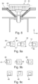
- Fig. 9a shows an example of the fittings 40 in a horizontal view.
- the fittings are shown with their connection shoes 44.
- the connection shoes 44 are slid on to the upper end of the connection studs 12, partly engaging the head portion.
- the relative movement is indicated with a first movement arrow 45 leading to the state of Fig. 9b .
- Fig. 9b shows the fittings of Fig. 9a in a pre-mounted state.
- the fittings are now turned in alternating directions. From the left: The first fitting is turned counter clockwise by approximately 90°. The second fitting is turned clockwise by approximately 90°. The third fitting is turned counter clockwise by approximately 90°. The movement is indicated with rotation arrows 47. The alternate rotation leads to a situation where a proper mount is given as the shoes can no longer moved in combination.
- Fig. 9c shows the fittings of Fig. 9b in a locked mounted state.
- the indicators 48 point in the same direction.
- Fig. 10 shows an example of an aircraft 150.
- the aircraft 150 comprises a fuselage 152 and a wing arrangement 154 attached to the fuselage.
- An aircraft cabin 156 is provided within the fuselage 152, the cabin 156 comprising a cabin floor 158.
- the cabin floor 158 comprises an example of the aircraft floor mounting system 50 according to one of the examples above.
- the cabin floor 158 is provided as an example of the floor arrangement 100 according to one of the examples above.
- Fig. 11 shows basic steps of an example of a method 200 for providing a fixation interface for an aircraft cabin floor.
- the method 200 comprises the following steps:
Landscapes
- Engineering & Computer Science (AREA)
- Mechanical Engineering (AREA)
- General Engineering & Computer Science (AREA)
- Aviation & Aerospace Engineering (AREA)
- Transportation (AREA)
- Connection Of Plates (AREA)
- Connector Housings Or Holding Contact Members (AREA)
Priority Applications (3)
| Application Number | Priority Date | Filing Date | Title |
|---|---|---|---|
| EP23200657.7A EP4530481A1 (de) | 2023-09-28 | 2023-09-28 | Anpassbare befestigungsschnittstelle für einen flugzeugkabinenboden |
| US18/888,986 US20250108906A1 (en) | 2023-09-28 | 2024-09-18 | Adaptable fixation interface for an aircraft cabin floor |
| CN202411348619.1A CN119726187A (zh) | 2023-09-28 | 2024-09-26 | 可适应固定接口、飞行器地板安装系统、飞行器地板装置、飞行器和用于向飞行器舱室地板提供固定接口的方法 |
Applications Claiming Priority (1)
| Application Number | Priority Date | Filing Date | Title |
|---|---|---|---|
| EP23200657.7A EP4530481A1 (de) | 2023-09-28 | 2023-09-28 | Anpassbare befestigungsschnittstelle für einen flugzeugkabinenboden |
Publications (1)
| Publication Number | Publication Date |
|---|---|
| EP4530481A1 true EP4530481A1 (de) | 2025-04-02 |
Family
ID=88236644
Family Applications (1)
| Application Number | Title | Priority Date | Filing Date |
|---|---|---|---|
| EP23200657.7A Pending EP4530481A1 (de) | 2023-09-28 | 2023-09-28 | Anpassbare befestigungsschnittstelle für einen flugzeugkabinenboden |
Country Status (3)
| Country | Link |
|---|---|
| US (1) | US20250108906A1 (de) |
| EP (1) | EP4530481A1 (de) |
| CN (1) | CN119726187A (de) |
Citations (3)
| Publication number | Priority date | Publication date | Assignee | Title |
|---|---|---|---|---|
| WO2011119719A1 (en) * | 2010-03-23 | 2011-09-29 | Be Aerospace Inc. | Passenger seat assembly with associated floor panel and aircraft sidewall attachment, and method |
| US20140131519A1 (en) * | 2012-11-14 | 2014-05-15 | Airbus Operations Gmbh | Fastening arrangement for attaching a floor |
| US20190092478A1 (en) * | 2016-03-10 | 2019-03-28 | Zodiac Seats Us Llc | Track fitting adaptor |
Family Cites Families (1)
| Publication number | Priority date | Publication date | Assignee | Title |
|---|---|---|---|---|
| EP4574649A1 (de) * | 2023-12-18 | 2025-06-25 | Airbus Operations GmbH | Hochadaptierbare und multifunktionale sitzschiene für einen flugzeugkabinenboden |
-
2023
- 2023-09-28 EP EP23200657.7A patent/EP4530481A1/de active Pending
-
2024
- 2024-09-18 US US18/888,986 patent/US20250108906A1/en active Pending
- 2024-09-26 CN CN202411348619.1A patent/CN119726187A/zh active Pending
Patent Citations (3)
| Publication number | Priority date | Publication date | Assignee | Title |
|---|---|---|---|---|
| WO2011119719A1 (en) * | 2010-03-23 | 2011-09-29 | Be Aerospace Inc. | Passenger seat assembly with associated floor panel and aircraft sidewall attachment, and method |
| US20140131519A1 (en) * | 2012-11-14 | 2014-05-15 | Airbus Operations Gmbh | Fastening arrangement for attaching a floor |
| US20190092478A1 (en) * | 2016-03-10 | 2019-03-28 | Zodiac Seats Us Llc | Track fitting adaptor |
Also Published As
| Publication number | Publication date |
|---|---|
| US20250108906A1 (en) | 2025-04-03 |
| CN119726187A (zh) | 2025-03-28 |
Similar Documents
| Publication | Publication Date | Title |
|---|---|---|
| CA2887456C (en) | Flight test equipment installation system and method | |
| US8408496B2 (en) | Fuselage cell structure of an airplane for the simplified installation and attachment of fasteners for fastening conduits | |
| EP2179920B1 (de) | Flugzeugkabinenbodenstrukturen, Systeme und Verfahren | |
| EP2733061B1 (de) | Befestigungsanordnung zum Anbringen eines Fußbodens | |
| US20190329907A1 (en) | Fastening system for fastening built-in elements in a cabin of a vehicle | |
| US7232095B2 (en) | Overhead rest assembly | |
| BRPI0616719A2 (pt) | painel de piso, instalaÇço para a fixaÇço de elementos de arranjo fÍsico em um veÍculo de transporte de passageiros, e, aeronave | |
| EP2481632B1 (de) | Modulares Adapterplattensystem | |
| CN109774914B (zh) | 地板组件以及带有地板组件的飞行器区域和飞行器 | |
| ES3049336T3 (en) | Connector and method for connecting a frame and a stringer of a fuselage structure of an aircraft, fuselage structure and aircraft | |
| US10773782B2 (en) | Interior component carrier system and method for mounting an interior component carrier system | |
| CN110155339B (zh) | 用于将组件紧固在载具中的轨道处的紧固系统 | |
| US9775411B2 (en) | System for mounting of components | |
| US20100038483A1 (en) | Seat track fittings | |
| CN113978323A (zh) | 用于公共交通车辆的座椅附接系统 | |
| CN110949673A (zh) | 用于飞机座椅的互连底座附接系统 | |
| US20240174341A1 (en) | Floor system for a cabin of a vehicle with form-fitting floor panel connection | |
| US20250108906A1 (en) | Adaptable fixation interface for an aircraft cabin floor | |
| US20090014586A1 (en) | Light rail system for powered introduction of large loads in a structure | |
| US12012211B2 (en) | Carrier device, seating area divider and vehicle cabin | |
| US10780981B2 (en) | Aircraft seat rail mounting member | |
| US20250197011A1 (en) | Highly adaptable and multifunctional seat rail for an aircraft cabin floor | |
| US20220267012A1 (en) | Two-Piece Mounting Rail For A Vehicle | |
| EP4470908A1 (de) | Montageschiene | |
| US11708165B2 (en) | Rail arrangement for an inner space of an aircraft |
Legal Events
| Date | Code | Title | Description |
|---|---|---|---|
| PUAI | Public reference made under article 153(3) epc to a published international application that has entered the european phase |
Free format text: ORIGINAL CODE: 0009012 |
|
| STAA | Information on the status of an ep patent application or granted ep patent |
Free format text: STATUS: THE APPLICATION HAS BEEN PUBLISHED |
|
| AK | Designated contracting states |
Kind code of ref document: A1 Designated state(s): AL AT BE BG CH CY CZ DE DK EE ES FI FR GB GR HR HU IE IS IT LI LT LU LV MC ME MK MT NL NO PL PT RO RS SE SI SK SM TR |
|
| STAA | Information on the status of an ep patent application or granted ep patent |
Free format text: STATUS: REQUEST FOR EXAMINATION WAS MADE |
|
| 17P | Request for examination filed |
Effective date: 20251002 |