EP4530266A1 - Heissformwerkzeug für glasflaschenhälse - Google Patents
Heissformwerkzeug für glasflaschenhälse Download PDFInfo
- Publication number
- EP4530266A1 EP4530266A1 EP23200284.0A EP23200284A EP4530266A1 EP 4530266 A1 EP4530266 A1 EP 4530266A1 EP 23200284 A EP23200284 A EP 23200284A EP 4530266 A1 EP4530266 A1 EP 4530266A1
- Authority
- EP
- European Patent Office
- Prior art keywords
- forming
- glass
- tool
- section
- forming tool
- Prior art date
- Legal status (The legal status is an assumption and is not a legal conclusion. Google has not performed a legal analysis and makes no representation as to the accuracy of the status listed.)
- Withdrawn
Links
Images


Classifications
-
- C—CHEMISTRY; METALLURGY
- C03—GLASS; MINERAL OR SLAG WOOL
- C03B—MANUFACTURE, SHAPING, OR SUPPLEMENTARY PROCESSES
- C03B23/00—Re-forming shaped glass
- C03B23/04—Re-forming tubes or rods
- C03B23/09—Reshaping the ends, e.g. as grooves, threads or mouths
- C03B23/092—Reshaping the ends, e.g. as grooves, threads or mouths by pressing
-
- C—CHEMISTRY; METALLURGY
- C03—GLASS; MINERAL OR SLAG WOOL
- C03B—MANUFACTURE, SHAPING, OR SUPPLEMENTARY PROCESSES
- C03B23/00—Re-forming shaped glass
- C03B23/04—Re-forming tubes or rods
- C03B23/09—Reshaping the ends, e.g. as grooves, threads or mouths
- C03B23/095—Reshaping the ends, e.g. as grooves, threads or mouths by rolling
-
- C—CHEMISTRY; METALLURGY
- C03—GLASS; MINERAL OR SLAG WOOL
- C03B—MANUFACTURE, SHAPING, OR SUPPLEMENTARY PROCESSES
- C03B23/00—Re-forming shaped glass
- C03B23/04—Re-forming tubes or rods
- C03B23/09—Reshaping the ends, e.g. as grooves, threads or mouths
Definitions
- FIGs 1 and 2 schematically illustrate an apparatus 1, known from the prior art, for hot forming of glass containers.
- Figure 1 shows the side view
- Figure 2 shows a plan view.
- the apparatus has an inner forming tool 40 (also referred to in the art as plug), which forms the inner lateral surface of a glass tube 30.
- the forming tool 40 in fig. 1 and 2 is a schematic representation.
- the outer shaping rollers 20 are mounted in a rotatable manner in the mounting suspension 60.
- the apparatus has a gas flame 70 for optionally heating the glass vial blank 30.
- the glass tube 30 is heated up to a temperature that makes the glass material formable. This heating up can be performed outside the forming tool and be optionally assisted by the gas flame 70 if desired.
- the temperature to which the glass is heated depends on the specific type of glass used and is typically in the range of Tg + 200 to Tg + 600°C (wherein Tg is the transition temperature of the glass).
- Tg is the transition temperature of the glass.
- the glass tube 30 is rotated.
- the forming tools 40 and 20 move towards the glass tube blank 30 to be formed. Since the outer forming tools 20 are mounted in a rotatable manner, they are likewise set in rotation by the rotary movement of the glass tube 30. Note that the forming tool 40 can be either fixed in place or be rotatable along the axial directing. Furthermore, during the forming of the outer lateral surface of the glass tube 30, the entire lateral surface of the outer shaping roller 20 passes into contact with the hot glass tube 30.
- the interaction of the inner shaping tool 40 and the outer shaping rollers 20 with the glass tube form the final geometry of the glass tube 30. This results in the final geometry of the opening of the tube.
- the invention is not limited to this implementation of the apparatus 1, and the forming tool can be used in other suitable forming machines, where a relative rotation between the forming tool 40 and the container to be formed is realized.
- FIG. 3 shows a three-dimensional view
- fig. 4 a top view is shown
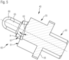
- Fig. 5 a cross section of the tool 40 is shown according to the section line A-A as indicated in Fig. 4 .
- the tool 40 has a base mounting shaft 50 that can engage with a production machine, like the one shown in Figs 1 and 2 .
- the mounting shaft 50 mounts securely on the production machine 1 which has an according coupling system.
- Such mounting mechanisms are known in the art.
- On top of the mounting shaft is a mounting ring 55.
- the ring 55 is provided with cut outs 56.
- the ring 55 forms together with the mounting shaft 50 a mounting system 56.
- a forming section 60 is mounted, therefore on the distal end of the mounting system 56.
- the forming section 60 has two flat forming surfaces or planar end surfaces 61, 62.
- the end surfaces 61, 62 are perpendicular to the center axis of the tool 40.
- Adjacent to the end surfaces 61 62 are two forming ramps 61, 62.
- the ramps 61, 62 have a slope X of 10 degrees compared to the planar end surfaces 61.
- On top of the mounting ring 55 and starting at the level of the end surfaces 61 a ring forming section 67 is located.
- the ring forming section 67 is concentrical with the center axis of the tool 40.
- the ring forming section 67 has cut out sections 63 and 64.
- top forming section 66 located concentrically with the center axis of the tool 40.
- the topmost section of the top forming section 66 is dome shaped in this example.
- the top forming section 66 is provided with two cutouts 65, extending in axially in the wall section of the top forming section 66. The cutouts 65 are facing to the corresponding cut out sections 63.
- the glass vial 30 to be formed is heated up to the temperature that makes the glass formable, so that it is a semi liquid state and can be formed into a specific shape.
- the top section 60 is inserted coaxially into the glass vial 30.
- the planar forming surfaces 61 engage with the glass vial 30.
- the forming rollers 20 also engage the vial 30 at the outside. Due the rotation of the glass vial 30, the formable glass of the vial 30 is engaging with the ramps 62, as well as with the cutout sections 63 and 64, under the pressure generated between the forming tool 40 and the forming rollers.
- the ramps 62 push the now formable, semi liquid glass within the forming space formed by the forming tool 40 and the forming rollers to move the glass mass into the shape.
- the cutout sections 63 and 64 in addition engage with the flowing glass and further direct and push the glass material through the forming space. Due to the ramps 62 the glass can be moved around more efficiently throughout the forming space, with further assistance from the cutout sections 63 and 64 which further distribute the glass throughout the forming space. By more efficiently pushing the glass throughout the forming space, complete filling out of the forming space can be ensured.
- complex geometries can be formed. In particular, geometries with a narrow cross section, that is a thin glass wall, can be formed without risking the form not being fill out fully.
- the angle of the surface 63 is about 60 - 70°.
- the surface 64 ends in the middle of the plug (angle 20-30°).
- the inclined position of the plug and the phases 63 and 64 reduces the contact area with the forming tools. This reduces the force acting on the glass. This leads to a gentler shaping or the vial collar contour.
- the phases 64 and 63 ensure that the glass accumulates better in the middle of the inner contour of the collar surface and there are fewer defects and imbalances.
- the slope X of the ramps 62 is 10 degrees.
- the invention can be implemented with slopes X between 5-15 degrees.
- the angle can be chosen depending on the flow characteristics of the specific glass used and the required geometry.
- the ring forming section 67 is concentrical with the center axis of the tool 40 and does not contain the cut-out sections 63 and 64. In this case the ring forming section is cylindrical. In use, the ramps 62 still function as described before, with minor loss of the additional forming functions of the sections 63 and 64. The tool according to this example is easier to manufacture. In a further example of the invention, the ring forming section 67 is provided with the section 63 but leaves out the section 64. This has improved flow direction effects, while keeping the manufacturing costs lower.
- an additional heater for example a gas flame 70 as shown in fig. 1 can be used to heat the glass before and/or during forming. This improves the temperature control of the glass during forming and provides additional ease of flow of the glass when being formed.
- the tool can be assembled from multiple parts, but preferably the tool is formed out of a single work piece to improve strength and reliability as no parts can come loose during use.
- a single piece construction also has the advantage to reduce vibrations in use.
- the plug can be made out of a hardened highspeed steel.
Landscapes
- Chemical & Material Sciences (AREA)
- Engineering & Computer Science (AREA)
- Materials Engineering (AREA)
- Organic Chemistry (AREA)
- Re-Forming, After-Treatment, Cutting And Transporting Of Glass Products (AREA)
- Containers Having Bodies Formed In One Piece (AREA)
Priority Applications (4)
| Application Number | Priority Date | Filing Date | Title |
|---|---|---|---|
| EP23200284.0A EP4530266A1 (de) | 2023-09-28 | 2023-09-28 | Heissformwerkzeug für glasflaschenhälse |
| US18/885,863 US20250109054A1 (en) | 2023-09-28 | 2024-09-16 | Hot forming tool for glass bottle necks |
| EP24200466.1A EP4530267A1 (de) | 2023-09-28 | 2024-09-16 | Heissformwerkzeug für glasflaschenhälse |
| CN202411298828.XA CN119707261A (zh) | 2023-09-28 | 2024-09-18 | 用于玻璃瓶颈部的热成型工具 |
Applications Claiming Priority (1)
| Application Number | Priority Date | Filing Date | Title |
|---|---|---|---|
| EP23200284.0A EP4530266A1 (de) | 2023-09-28 | 2023-09-28 | Heissformwerkzeug für glasflaschenhälse |
Publications (1)
| Publication Number | Publication Date |
|---|---|
| EP4530266A1 true EP4530266A1 (de) | 2025-04-02 |
Family
ID=88290924
Family Applications (2)
| Application Number | Title | Priority Date | Filing Date |
|---|---|---|---|
| EP23200284.0A Withdrawn EP4530266A1 (de) | 2023-09-28 | 2023-09-28 | Heissformwerkzeug für glasflaschenhälse |
| EP24200466.1A Pending EP4530267A1 (de) | 2023-09-28 | 2024-09-16 | Heissformwerkzeug für glasflaschenhälse |
Family Applications After (1)
| Application Number | Title | Priority Date | Filing Date |
|---|---|---|---|
| EP24200466.1A Pending EP4530267A1 (de) | 2023-09-28 | 2024-09-16 | Heissformwerkzeug für glasflaschenhälse |
Country Status (3)
| Country | Link |
|---|---|
| US (1) | US20250109054A1 (de) |
| EP (2) | EP4530266A1 (de) |
| CN (1) | CN119707261A (de) |
Citations (4)
| Publication number | Priority date | Publication date | Assignee | Title |
|---|---|---|---|---|
| EP3677554A1 (de) | 2018-10-19 | 2020-07-08 | SCHOTT Schweiz AG | Verfahren und vorrichtung zur heissformung von gläsernen werkstücken und heissumgeformte glasbehälter |
| US20200354255A1 (en) | 2018-01-26 | 2020-11-12 | Schott Schweiz Ag | Method and device for hot-shaping glass containers |
| US20210276912A1 (en) * | 2020-03-03 | 2021-09-09 | Schott Ag | Installation, device, and method for shaping the mouth of a hollow-body-shaped precursor from glass |
| US20210363048A1 (en) * | 2017-12-22 | 2021-11-25 | Nipro Corporation | Method and apparatus of manufacturing glass products |
Family Cites Families (1)
| Publication number | Priority date | Publication date | Assignee | Title |
|---|---|---|---|---|
| JP2021183304A (ja) | 2020-05-21 | 2021-12-02 | 株式会社ディスコ | 純水生成装置、及び紫外線照射ユニット |
-
2023
- 2023-09-28 EP EP23200284.0A patent/EP4530266A1/de not_active Withdrawn
-
2024
- 2024-09-16 US US18/885,863 patent/US20250109054A1/en active Pending
- 2024-09-16 EP EP24200466.1A patent/EP4530267A1/de active Pending
- 2024-09-18 CN CN202411298828.XA patent/CN119707261A/zh active Pending
Patent Citations (4)
| Publication number | Priority date | Publication date | Assignee | Title |
|---|---|---|---|---|
| US20210363048A1 (en) * | 2017-12-22 | 2021-11-25 | Nipro Corporation | Method and apparatus of manufacturing glass products |
| US20200354255A1 (en) | 2018-01-26 | 2020-11-12 | Schott Schweiz Ag | Method and device for hot-shaping glass containers |
| EP3677554A1 (de) | 2018-10-19 | 2020-07-08 | SCHOTT Schweiz AG | Verfahren und vorrichtung zur heissformung von gläsernen werkstücken und heissumgeformte glasbehälter |
| US20210276912A1 (en) * | 2020-03-03 | 2021-09-09 | Schott Ag | Installation, device, and method for shaping the mouth of a hollow-body-shaped precursor from glass |
Also Published As
| Publication number | Publication date |
|---|---|
| EP4530267A1 (de) | 2025-04-02 |
| CN119707261A (zh) | 2025-03-28 |
| US20250109054A1 (en) | 2025-04-03 |
Similar Documents
| Publication | Publication Date | Title |
|---|---|---|
| DE2805321C2 (de) | ||
| JP3053219B2 (ja) | ハブを有する伝動装置部材のハブを切削によらずに製造する方法 | |
| EP3743388B1 (de) | Verfahren und vorrichtung zur heissformgebung von glasbehältnissen | |
| US20070017089A1 (en) | Bottle manufacturing equipment | |
| KR20130100347A (ko) | 파이프부를 성형하기 위한 방법 | |
| HU188156B (en) | Method for producing thin-walled one-section metal bodies first for pressure vessels and the hollow metal body produced by the method | |
| WO2019108803A1 (en) | Glass article made from laminated glass tubing, system and method for converting laminated glass tubing into the glass articles | |
| JP2013078802A (ja) | 予備フラップ形成加工を伴う金属包装容器用の加工装置 | |
| JP5976153B2 (ja) | 金属製カンの製造装置 | |
| EP4530266A1 (de) | Heissformwerkzeug für glasflaschenhälse | |
| EP3652120B1 (de) | Heissformgebungswerkzeug für die herstellung von glascontainern | |
| CN113415980B (zh) | 用于成型由玻璃制成的中空体状预型件的开口的装置、设备以及方法 | |
| GB2332160A (en) | Can base reforming | |
| EP1369392B1 (de) | Maschine zur kontinuierlichen Herstellung von Glasampullen oder von ähnlichen Behältern der gleichen Grösse | |
| KR102387724B1 (ko) | 보틀 캔 제조 장치 및 보틀 캔 제조 방법 | |
| US5428980A (en) | Method and apparatus for producing cap for drink bottle | |
| EP4711344A1 (de) | Heissformwerkzeug für glasflaschenhälse | |
| WO2008095272A1 (en) | Closed die for forging irregular-shaped parts | |
| US3257186A (en) | Method of and apparatus for reshaping glass tubes | |
| US12172406B2 (en) | Device for manufacturing double walled paper cups | |
| EP3743389B1 (de) | Heissformgebungsvorrichtung zur herstellung von glasbehältnissen aus einem glasrohr | |
| JPH03501825A (ja) | 長楕円形の作業片を機械加工する方法及びそのための装置 | |
| KR20160101996A (ko) | 클래딩된 부품의 제조 방법 | |
| JPH0811261B2 (ja) | 瓶状金属容器の底付け加工方法とその装置 | |
| US1046138A (en) | Method of forming flanges on pipes. |
Legal Events
| Date | Code | Title | Description |
|---|---|---|---|
| PUAI | Public reference made under article 153(3) epc to a published international application that has entered the european phase |
Free format text: ORIGINAL CODE: 0009012 |
|
| STAA | Information on the status of an ep patent application or granted ep patent |
Free format text: STATUS: THE APPLICATION HAS BEEN PUBLISHED |
|
| AK | Designated contracting states |
Kind code of ref document: A1 Designated state(s): AL AT BE BG CH CY CZ DE DK EE ES FI FR GB GR HR HU IE IS IT LI LT LU LV MC ME MK MT NL NO PL PT RO RS SE SI SK SM TR |
|
| STAA | Information on the status of an ep patent application or granted ep patent |
Free format text: STATUS: THE APPLICATION IS DEEMED TO BE WITHDRAWN |
|
| 18D | Application deemed to be withdrawn |
Effective date: 20251003 |