EP4530226A1 - Automatisiertes regalbediensystem; logistiksystem und verfahren zum handhaben mehrerer gegenstände - Google Patents
Automatisiertes regalbediensystem; logistiksystem und verfahren zum handhaben mehrerer gegenstände Download PDFInfo
- Publication number
- EP4530226A1 EP4530226A1 EP23200953.0A EP23200953A EP4530226A1 EP 4530226 A1 EP4530226 A1 EP 4530226A1 EP 23200953 A EP23200953 A EP 23200953A EP 4530226 A1 EP4530226 A1 EP 4530226A1
- Authority
- EP
- European Patent Office
- Prior art keywords
- vehicle
- items
- suspension
- arrangement
- vehicles
- Prior art date
- Legal status (The legal status is an assumption and is not a legal conclusion. Google has not performed a legal analysis and makes no representation as to the accuracy of the status listed.)
- Pending
Links
Images


Classifications
-
- B—PERFORMING OPERATIONS; TRANSPORTING
- B65—CONVEYING; PACKING; STORING; HANDLING THIN OR FILAMENTARY MATERIAL
- B65G—TRANSPORT OR STORAGE DEVICES, e.g. CONVEYORS FOR LOADING OR TIPPING, SHOP CONVEYOR SYSTEMS OR PNEUMATIC TUBE CONVEYORS
- B65G1/00—Storing articles, individually or in orderly arrangement, in warehouses or magazines
- B65G1/02—Storage devices
- B65G1/04—Storage devices mechanical
- B65G1/0464—Storage devices mechanical with access from above
-
- B—PERFORMING OPERATIONS; TRANSPORTING
- B62—LAND VEHICLES FOR TRAVELLING OTHERWISE THAN ON RAILS
- B62D—MOTOR VEHICLES; TRAILERS
- B62D65/00—Designing, manufacturing, e.g. assembling, facilitating disassembly, or structurally modifying motor vehicles or trailers, not otherwise provided for
- B62D65/02—Joining sub-units or components to, or positioning sub-units or components with respect to, body shell or other sub-units or components
- B62D65/18—Transportation, conveyor or haulage systems specially adapted for motor vehicle or trailer assembly lines
-
- B—PERFORMING OPERATIONS; TRANSPORTING
- B65—CONVEYING; PACKING; STORING; HANDLING THIN OR FILAMENTARY MATERIAL
- B65G—TRANSPORT OR STORAGE DEVICES, e.g. CONVEYORS FOR LOADING OR TIPPING, SHOP CONVEYOR SYSTEMS OR PNEUMATIC TUBE CONVEYORS
- B65G1/00—Storing articles, individually or in orderly arrangement, in warehouses or magazines
- B65G1/02—Storage devices
- B65G1/04—Storage devices mechanical
- B65G1/0457—Storage devices mechanical with suspended load carriers
Definitions
- the present invention relates to a method and a system for storing and retrieving of a plurality of items, especially performed by an automated storage and retrieval system.
- a known storage technology is the AutoStore system, an automated storage and retrieval system (AS/RS).
- AS/RS automated storage and retrieval system
- the technology revolves around the storage of goods in bins, which are stacked directly on top of each other and can be accessed and transported using a combination of robots and a grid system.
- This system contains the following technology components:
- the international patent application WO2022106598 presents a method, a depot facility and a system for handover of a plurality of parcels to a plurality of recipients and/or to receive a large number of parcels from multiple depositors as well as a logistics system with an associated ordering system which can be integrated into eProcurement applications and eCo-mmerce applications.
- the international patent application WO2023073012 presents a method and a system for handover of a plurality of parcels to a plurality of recipients and/or for receiving a plurality of parcels from a plurality of depositors.
- a method is provided for handover of a plurality of goods objects to a plurality of recipients, wherein the goods objects are stored and/or transported in parcels and transferred to a depot facility and then stored in the depot facility.
- the European patent EP2042277B1 describes a gripping tool for one or more workpieces, having a frame, having a connection for a manipulator and having a plurality of gripping units, wherein the frame has more than two frame members connected together in an articulated manner and at least one controllable actuating device for the mutual adjustment thereof.
- the European patent EP3803727B1 describes a method for providing process protocols for a number of physical objects (O) passing through a plurality of production/processing stations (P1... Pn) in a production/processing line, wherein machine-readable data (D) are assigned to at least one object (O), wherein the data comprise at least one identifier by means of which the relevant object can be uniquely identified, wherein the process protocol is continuously generated by continuous addition.
- the invention is based on the task of providing a method, a storage facility and a system for handling of a plurality of items so that the items can be processed quickly and reliably.
- this task is solved by an automated storage and retrieval system, a method and by a logistics system according to the independent claims.
- the present application is part of an overarching concept whose goal is to perform processing operations of items as automated as possible and preferably also contactless and/or autonomously and with the smallest possible ecological footprint.
- the invention especially proposes an automated storage and retrieval system for the storing of items, e.g. of goods objects in containers in a storing arrangement, characterized in that a suspension arrangement for lifting, transferring and lowering the containers is arranged oriented to at least one transfer area for the items, e.g.
- the suspension arrangement comprises at least one vehicle and a structure extending in at least two spatial directions, wherein the structure comprises a plurality of profile units extending in a first spatial direction, wherein the structure defines in at least a part of its surface at least one structural regularity in a second spatial direction; and wherein the at least one vehicle comprises a plurality of suspension elements configured for suspending the at least one vehicle, wherein the at least one vehicle comprises at least one vehicle, wherein the at least one vehicle comprises a gripping unit, wherein the gripping unit is configured to connect to at least one item; and wherein the suspension arrangement is configured for active motion of the vehicle in said first spatial direction and/or said second spatial direction.
- the suspension arrangement for lifting, transferring and lowering the containers is arranged oriented to at least one transfer area, especially means that the suspension arrangement faces an area, where a transfer of items between the storing arrangement and the gripping units of the vehicles movable along the suspended structure can occur.
- the storing arrangement and the suspension arrangement are separated from each other, especially allowing a free and uninterrupted movement of the vehicles wherein a stop of the vehicles only occurs close to items, wherein the only contact between the vehicles and the items and/or the storing arrangement occurs through the gripping units of the vehicles.
- the crawler type vehicle can exhibit at least one motor/actuator for actively driving the crawler type vehicle along the structure.
- the crawler type vehicle follows an intended direction resp. an intended path of motion, especially in conjunction with appropriate sensor-actor-arrangements.
- the suspension arrangement is configured for active motion of the vehicle / the vehicles includes all embodiments wherein the vehicle/s can move on its/their own.
- actively moving designates a motion of the vehicle in relation to the structure actuated preferably by an electric motor of the vehicle connected to a drive unit such that the vehicle can move on its own inside the structure when the motor is activated.
- the choice of an appropriate motor can be carried out by the person skilled in the art in regard to existing motors and motor arrangements depending on the respective application / task / size of the respective vehicle, e.g., crawler type vehicle.
- Gripping units often referred to as end effectors or end-of-arm tooling (EOAT) in the context of logistics, but also known from automation and robotics, are devices designed to interact with items, especially different items. Their design is influenced by the size, shape, weight, surface and material properties of the items to be handled. Examples of gripping units which can be tailored to handle items as described in the current application text are:
- Gripping units according to the present invention may include gripping elements, especially as mentioned above and/or described in other parts of this application text as well potentially also an elongator, especially an arm, preferably an extendable/expandable robot arm.
- the current application text describes certain options for handling the items after their retrieval from the automated storage and retrieval system including by at least one logistic process of a logistics system, preferably by a handling of the items and/or of goods objects as parcels.
- object identification features as sensors for QR code reading or sensors for RFID tag reading.
- the items are durable.
- the described examples are not limited to embodiments where the items remain stable and/or unchanged over time. It is useful to monitor a status of the items, e.g., by an integration of inspection equipment.
- the automated storage and retrieval system is designed with regard of the physical or rather physical properties of the items to be stored and retrieved and adapted to available space.
- the present invention is not limited to a handling of conventional bins.
- conventional bins as described in the state of the art as for example the AutoStore bins or any other stackable bin as well as other bins, e.g., also nesting bins can be handled as items by automated storage and retrieval systems described in the current patent application.
- the present invention provides for integrating a suspension arrangement exhibiting at least one vehicle and a structure extending in at least two spatial directions, wherein the structure comprises a plurality of profile units (especially rails) extending (preferably continuously, especially without any structural discontinuity) in a first spatial direction, wherein the structure defines at least one structural regularity in a second spatial direction (thereby providing a one-dimensional raster with discrete coupling points distributed in at least one equidistant regularity in said second spatial direction).
- the vehicle is especially a crawler type vehicle that exhibits a plurality of suspension elements configured for suspending the vehicle and configured for coupling the crawler type vehicle to the structure by means of de-/coupling kinematics depending on a relative motion of the vehicle with respect to the structure in at least said second spatial direction, wherein the (crawler type) vehicle comprises means for providing for de-/coupling kinematics during a motion of the crawler type vehicle in said second spatial direction, especially with the crawler type vehicle being configured to be moved in said first spatial direction along the profile units irrespective of momentary motion in said second spatial direction.
- All vehicles according to the present description can be designed as any of the crawler type vehicles described in this patent application text.
- structure when it is referred to "structure", a structure that predominantly extends along a Vertical plane or horizontal plane or even along an inclined plane (or the like) is designated.
- the present invention is applied for vehicles being arranged at resp. traveling along a structure, and in addition, the present invention also allows for any motion along any structure with alternative orientation and/or arrangement.
- referring to a “structure” includes reference to any other “structure” exhibiting the features presently described allowing for coupling with/to the inventive vehicle and corresponding de-/coupling kinematics.
- profile units or “profiles” or “T-profiles”
- T-profiles the disclosure also generally refers to different kinds of profiles like e.g. I-profiles or L-profiles which may provide for advantageous/favorable arrangements in individual applications.
- each suspension element exhibits at least one element of motion (for gliding or rolling, especially at least one wheel) arranged and configured for actively moving (especially gliding or rolling) the vehicle in said first spatial direction.
- each suspension element exhibits at least two elements of motion, e.g., a main wheel and a side wheel (side friction wheel of a roller coaster) clamping the profile unit from at least two sides.
- vehicle when it is referred to "vehicle”, the disclosure generally refers to vehicles, capable of moving along the suspension structure.
- vehicles or vehicles connectable to the relative spatial arrangement or traveling motion are preferred.
- the vehicle exhibits one or more load attachment points configured for connecting to gripping unit to interact with one or more item.
- the vehicle can exhibit at least one motor/actuator for actively driving the vehicle along the structure.
- the vehicle follows an intended direction resp. an intended path of motion, especially in conjunction with appropriate sensor-actor-arrangements.
- the suspension structure can exhibit at least one energy charging point/position/area, wherein the suspension structure is configured for charging/providing the at least one vehicle with energy when being arranged in/at said energy charging point/position/area.
- the charging area covers at least one charging section or the whole structure.
- the first sliders are connected to the power rail in the structure before the second sliders are in proximity or connected to the conducting rail in the vehicle and when the suspension elements are decoupled from the structure, the second sliders are disconnected from the conducting rails before the first sliders are disconnected from the conducting rail. This can reduce wear on the electric rails in the structure and shifts potential wear into the vehicle sliding contacts which are considered to be simpler to restore by maintenance actions.
- At least two conducting rails are placed in parallel at least to sections of the described circumferential tracks (see above), wherein at least two suspension elements for establishing an electrical connection comprise means for dis-/connecting from/to the conducting rails, when the suspension elements are de-/coupled from/into the structure.
- the conducting rails can be integrated into the vehicle particularly easily, when the first drive unit has a race-course shape, wherein the suspension elements that are currently coupled into the structure are following a straight or linear section.
- Arranging two conducting rails in parallel can mean to place them on opposite sides at the same height of the drive unit, on one side at different heights with respect to the plane in which the structure is extending, or on opposite sides at different heights.
- first drive unit If only one first drive unit is used, it has proven beneficial to place the conducting rails on opposite sides. However, for scalability and easier integration process of more drive units, it can be beneficial to arrange two conducting rails at different heights on one side, because another drive unit, also exhibiting conducting rails in the same fashion could be integrated into the first drive unit in a mirror-inverted manner.
- the suspension elements configured for establishing an electrical connection with the structure can exemplarily be distributed along the at least one first drive unit such that, when the vehicle is moving along the structure, a suspension element for the electrical connection of a respective pole/phase is coupled into the structure before an otherwise last/only suspension element connected to the respective pole/phase is decoupled from the structure .
- This helps to ensure an uninterrupted connection with the respective pole/phase while moving the vehicle on the structure.
- every suspension element is configured for establishing an electrical connection with the structure. This can be beneficial for applications where a particularly high amount of power is to be transferred via the suspension elements because the current can be distributed over many suspension elements, reducing heat creation and wear of the components.
- the whole structure exhibits poles/phases of the power bus.
- the vehicle and structure have to be coordinated such that there is always one suspension element of a corresponding pole/phase connecting to the bus in the structure by coupling the suspension element into the structure before the otherwise last suspension element that is currently connected to the same pole/phase in the structure gets disconnected from the bus from a decoupling process of the suspension element.
- the vehicle or the plurality of vehicles exhibit/s at least two independently controllable motors, wherein at least one motor is configured for driving a motion in the first spatial direction (x) and at least one further motor is configured for driving a motion in the second spatial direction (y).
- Each power unit, drive, motor and/or actuator of the vehicle can be coupled to a control unit of the vehicle.
- the vehicle may exhibit two or three drive units which can be arranged in predefined lateral distance to each other (e.g. defined/connected via cross-beams or the like), and each drive unit may exhibit at least one drive/motor for actively driving the suspension elements along the circumferential tracks or the vehicle in the second spatial direction, and these drives/motors can be controlled depending on each other, e.g. via the speed of rotation.
- a traveling direction can be controlled in combination with actively driven wheels of the suspension elements being driven along the profile rails of the structure.
- the suspension elements can e.g., be connected via a spur gear to a motor.
- the wheels of the suspension elements can also or alternatively exhibit gear grooves to interact with a corresponding contour integrated into a "bottom" side of the profile unit, wherein "bottom” indicates the side of the profile unit facing the vehicle.
- the vehicle can alternatively or in addition exhibit at least one second kind of a drive unit configured for enabling locomotion of the vehicle in the first spatial direction.
- the first drive units of the vehicle can be scaled up in number, e.g., the vehicle exhibits three first drive units each being based on the same kinematic concept, but at least one of these drive units providing for mirror-inverted type/manner of de-/coupling kinematics.
- the second kind of drive unit can, e.g., comprise a holonomic wheel, or an elongated gearing wheel, that is able to be moved in the second spatial direction while moving the vehicle in the first spatial direction when driven.
- a holonomic wheel is a wheel whose wheel tread consists of rollers whose axes of rotation are at an angle to the axis of rotation of the main wheel.
- the absolute angle between the axes can for example be any angle between 5 and 90 degrees, especially 45 degrees. This angle has to be regarded when controlling the at least two motors, since the movement of the first drive units and the second drive unit are not independent in the case that the angle of the rollers to the wheel is different than 90 degrees.
- An angle smaller than 90 degrees can result in advantageous configurations regarding the traction of the holonomic wheel with the profiles of the structure.
- the holonomic wheel can e.g., be disc shaped and comprise a plurality of equally distributed rollers around its circumference, such that it allows for traction control in the first spatial direction and is not affected by a motion in the second spatial direction.
- the vehicle or the plurality of vehicles comprise/s a holonomic wheelset exhibiting gear grooves for form fit coupling, especially with a bottom side of the profile units.
- the bottom side of the profile units needs to exhibit corresponding teeth to form fit with the gear grooves of the holonomic wheelset.
- the gear grooves are distributed equidistantly along the circumference of each holonomic wheel of the wheelset.
- the holonomic wheel set comprises at least two coaxially arranged holonomic wheels.
- the coaxially arranged holonomic wheels are e.g., disc shaped and have a thickness that is half the width of the profiles of the structure, such that there is room for at least two holonomic wheels of the holonomic wheelset to interact with one profile (rail) of the structure at all times.
- Each of the coaxially arranged holonomic wheels can have a predefined offset in the azimuthal direction in respect to their adjacent holonomic wheels.
- one holonomic wheel comprises n rollers, that are equally distributed around the circumference of the wheel, each wheel is offset by 180/n degrees with respect to its neighbors. This way, it can be ensured that there is always at least one wheel of the wheelset in contact with the profile of the structure such that slip is prevented.
- the vehicle or plurality of vehicles exhibit/s a return mechanism.
- a holonomic wheelset is connected to a return mechanism that applies a force to the holonomic wheel(s) pressing it/them against the structure.
- This configuration enhances traction of the holonomic wheel on the profiles (rails) of the structure additionally ensures form fit in the case that the holonomic wheels exhibit gear grooves and the structure exhibits corresponding teeth.
- the vehicle or the plurality of vehicles exhibits counter wheels.
- the counter wheels can also be connected to the return mechanism.
- the counter wheels are connected to a further first drive unit exhibiting two circumferential tracks (see above), wherein the counter wheels exhibit two pulleys at a lever arm, each of the pulley being connected to an individual track, such that the counter wheels are guided along the circumferential tracks when the vehicle is moving in the second spatial direction.
- the counter wheels can also exhibit gear grooves to mesh with gear teeth in the structure.
- the counter wheels press against the profile units from the side of the vehicle, enhancing force fit/form fit coupling.
- the first spatial direction (x) is parallel to the ground.
- This suspended system is advantageous in terms of coupling security between the vehicle/s and the structure/s. Especially heavy/large bins can be moved with this automated storage and retrieval system.
- the second spatial direction (y) is parallel to the ground.
- the structure is in this case preferably arranged at a vertical plane.
- This configuration allows for a particularly high number of transportations between handling positions, because the first spatial direction (x) pointing upwards, means that the movement speed in first spatial direction is determined by the second kind of drive unit, which can comprise e.g., the described holonomic wheelset and can work in general at higher speeds than the first drive unit.
- Handling positions are positions associated with the automated storage and retrieval system where at least one logistics operation with regards to at least one item, e.g. a storage, a packing, a commissioning, a bundling or a transport, especially a further transport by a transfer unit can occur.
- at least one logistics operation with regards to at least one item, e.g. a storage, a packing, a commissioning, a bundling or a transport, especially a further transport by a transfer unit can occur.
- parcels are understood to be any physical objects that can be transported and preferably do not exceed certain dimensions and/or a certain weight.
- Items of daily use such as consumables or foodstuffs are just as eligible as technical items and equipment.
- the items can be handled as parcels themselves or be packed in parcels.
- Parcels are unpackaged objects, packaged objects and repackaged objects, whereby in the case of packaged and repackaged objects the parcel comprises the packaging or repackaging and the object packaged therein.
- Mail items as well as advertising materials and brochures are also parcels within the meaning of this application, where appropriate.
- parcels are specifically referred to as data parcels or virtual parcels in this application, the parcels depicted in this application are physical parcels.
- Commodity objects are physical objects that can first be physically acted upon by the logistics system or a component of the logistics system and are then transferred into physical access of another entity.
- the other entity may be a recipient of the goods or a physical facility configured to exert physical means of action on behalf of the recipient.
- the transfer of physical availability over the commodity object occurs when the recipient has previously acquired the commodity object.
- the present invention is suitable both for use with individualised parcels, where it is relevant that a parcel with a previously defined content is transmitted to a recipient, and for use for dispensing goods, in particular bulk goods including such goods for which there is no defined recipient before or after storage, possibly even at the time of dispensing, but for which an unidentified person can also be the recipient, in particular when the storage facility is designed as a sales facility.
- the present invention is not limited to embodiments in which the commodity objects are permanently transferred to recipients, but also includes embodiments in which the commodity objects are made available to recipients in a returnable manner, wherein the time period may be fixed or variable.
- the time period may be fixed or variable.
- such goods objects can also be handled as parcels according to the invention.
- the handover of the parcels, in particular the plurality of parcels, takes place in particular as one delivery and/or as one removal of the parcels.
- the present application concerns handovers of parcels to recipients and/or handovers of parcels by depositors. If it is not specified that the handover is to a recipient, handovers by a depositor are also included. Likewise, if it is not specified in each case that it is a handover by a depositor, a handover to a recipient is also included. In the present application, handovers by a depositor are also referred to as delivery or acceptance, while handovers to a recipient are also referred to as delivery.
- Recipients within the meaning of the present invention are entities to which the logistics system or a component of the logistics system transfers or can transfer parcels or other items. Both natural persons and technical units can be recipients in the context of the present application.
- Depositors within the meaning of the present application are entities that hand over or can hand over parcels or other items to the logistics system or a component of the logistics system. Both natural persons and technical units can be depositors in the context of the present application. Natural persons or technical units that hand over parcels to the logistics system for a transport operation are also referred to as shippers in the context of the present application. In particular, shipper refers to those depositors who commission a transport of parcels, including a pick-up, if applicable. The present application includes embodiments in which the depositors of parcels are shippers.
- storage facilities are all facilities which enable goods, especially parcels to be made available for further handling, and/or handover to recipients and/or by depositors.
- the storage facility includes a means for storing the parcels.
- Means for storing the parcels are for example storage facilities designed like lockers.
- An important advantage of locker-like storage facilities is the combination of a safe and reliable storage of the parcels and an improved retrievability of the parcels, in particular during the intended transfer period.
- means for storing the parcels can also be other facilities that ensure safe and secure storage of the parcels.
- these facilities include means for protecting the parcels from unauthorised removal.
- the storage facilities are preferably each designed as a module. Preferably, this means that the storage facilities are separable components of a logistics system.
- the storage facility can itself be designed as a handover facility or realise functions of a handover facility or also have a handover facility which, in particular, can be designed as a lock in an operating state of the storage facility.
- An example provides that a control component controls the process.
- the control component is in particular a central component of one of the logistics systems presented in this application.
- the control component is designed in such a way that it controls as many or even all of the processing steps of the parcels as possible.
- the control component only controls individual process steps as described in this application.
- control component of the logistics system can be designed in such a way that the control component can carry out individual or several or even all of the procedures presented in this application.
- An example is characterised by the fact that additional local logistics are provided at a storage facility so that, in addition to the parcels provided for handover at the joint handover points, goods objects can be delivered to the storage facility, stored and handed over to recipients as parcels. This results in an additional integration of local logistics.
- transfer periods can be defined depending on expected order orders.
- At least some of the order requests can be made via an ordering system, wherein the ordering system is in particular a system for ordering deliveries of parcels and/or collections of parcels.
- a first part of the order requests can be made via an ordering system and a second part of the order requests can be made directly at the storage facility.
- Transfer units within the meaning of the present application are all units that are designed to be able to transport parcels between a distribution centre and at least one storage facility.
- distribution centre includes, in particular, large handling centres of a logistics service provider for parcels.
- the logistics system comprises at least one inbound distribution centre.
- a parcel is sorted for the first time after it is received by the logistics service provider from the shipper for further transport to the delivery area.
- the logistics system comprises at least one outbound distribution centre.
- the parcel In the outbound distribution centre, the parcel is sorted to a specific delivery depot after delivery from the inbound distribution centre.
- a parcel identification characteristic is a unique data element that is physically and/or virtually assigned to the parcel and enables its reliable identification, in particular its unique identification.
- the reliable identification can refer to one or more process steps or to the entire logistics process from the delivery of a parcel to the output of the parcel. It is particularly advantageous that the parcel identification characteristic relates to the entire logistics process, but the use of the parcel identification characteristic in fewer process steps than the overall process is also encompassed by the invention.
- a parcel identification characteristic preferably includes one or more characteristics which, alone or in combination with each other and/or in combination with information about one or more processing operations of a parcel, allow a reliable identification of the parcel.
- individual In order to facilitate or enable the autonomous handling of parcels, individual, several and particularly preferably as many as possible of the processing units shown in this application, in particular storage facilities or transfer units, are preferably equipped with a means for detecting parcel identification characteristics of the parcels and for handling the parcels according to the parcel identification characteristics.
- the handling of the parcels according to the parcel identification characteristics supports an autonomous handling of the parcels. It is particularly advantageous to design the transfer units in such a way that they can carry out autonomous handling of the parcels.
- Appropriate measures for autonomous handling of the parcels relate in particular to:
- An example is characterised in that a singular transfer of the parcels takes place by means of at least one movable transport unit, wherein the movable transport unit is controllable in such a way that it can transfer the singularised parcels into the storage positions of the storage facility of the storage facilities, taking into account the parcel identification characteristics.
- a parcel identification code is in particular a code which is used to identify the parcel and which is in particular physically and/or virtually connected to the parcel, whereby it is particularly advantageous if the parcel identification code is also physically connected to the parcel. This applies in particular if the parcel identification code is used as a parcel identification characteristic or as one of the parcel identification characteristics.
- An appropriate embodiment of the system provides that at least some of the goods objects can be dispensed at the storage facility where they were handed over as parcels.
- the invention can also be described by the following characteristics.
- the characteristics presented below can be combined with each other as well as with the following presentation of preferred embodiments based on the figures, whereby particularly preferred combinations of characteristics are highlighted by reference to previously presented combinations of characteristics.
- the storing arrangement and the suspension arrangement are separated from each other, especially allowing a movement of the vehicles and a wherein a stop of the vehicles close to items, wherein no direct contact between the vehicles and the storing arrangement occurs, but only between the gripping units of the vehicles and the items which are storing arrangement occurs stored and/or retrieved.
- the automated storage and retrieval system further comprise at least one route planning tool for route planning along the at least one structure.
- the at least one vehicle can exhibit a sensing device exhibiting at least one sensor from the following group: speed sensor, distance sensor, height and position measuring sensor, force sensor, acceleration sensor resp. gyroscope.
- the automated storage and retrieval system is configured for transmitting commands to a communication unit of the at least one vehicle, especially to the communication units of all vehicles individually, such that control units of the vehicles control their respective vehicle based on received commands as well as based on momentary measuring data of at least sensor.
- the communication unit can be configured for wireless communication at least within the automated storage and retrieval system, wherein the (respective) vehicle or the suspension structure provides energy to the communication unit, especially such that the communication unit of the vehicle is energetically self-sustaining (autarkic) for at least a period of several days or weeks or month.
- the automated storage and retrieval system can be configured for localizing individual vehicles based on at least one locating signal transmitted by individual vehicles (passively or actively, e.g., passively based on at least one individual transmitter, especially based on individual identification features). Additionally, the vehicles transmit sensor data and information about destination handling positions to the at least one route planning tool when a request to do so is received in the communication unit of the vehicle.
- a route-planning tool plans a path for at least one vehicle connected to at least one gripping unit along at least one structure from one handling position to another, especially taking into account at least momentary positions and paths of at least one other vehicle, especially all vehicles also coupled to the at least one structure, wherein the vehicle moves omnidirectionally along the at least one structure, especially allowing for (fast) passing maneuvers. This increases the number of transportations between handling positions.
- a computer implemented method for route-planning for an automated storage and retrieval system comprising the following steps:
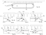
- Figs. 1 to 11 refer to embodiments, wherein the vehicles are designed as crawler type vehicles.
- Figs. 12 , 13 , 14 , 15 , 16 , 17 , 18 , 19 refer to an integration of suspended vehicles in embodiments of described automated storage and retrieval systems general. However, it is preferred to integrate crawler type vehicles as described Figs. 1 to 5c as vehicles in the embodiments according to Figs. 6 ff.
- the vehicles can exhibit at least one motor/actuator for actively driving the vehicle along the structure.
- each vehicle follows an intended direction resp. an intended path of motion, especially in conjunction with appropriate sensor-actor-arrangements.
- the suspension structure can exhibit at least one energy charging point/position/area, wherein the suspension structure is configured for charging/providing the at least one vehicle with energy when being arranged in/at said energy charging point/position/area.
- the charging area covers at least one charging section or the whole structure.
- a suspension arrangement that comprises at least one vehicle and a structure extending in at least two spatial directions, wherein the structure comprises a plurality of profile units extending in a first spatial direction, wherein the structure defines in at least a part of its surface at least one structural regularity in a second spatial direction; and wherein the at structure comprises a plurality of suspension elements configured for suspending the at least vehicle, wherein the at least one vehicle comprises at least one vehicle, wherein the at least one vehicle comprises a gripping unit, wherein the gripping unit is configured to connect to at least one container; and wherein the suspension arrangement is configured for active motion of the vehicle in said first spatial direction and/or said second spatial direction for lifting, transferring and lowering the containers parallel to at least one transfer area for the containers in an appropriate distance from the adjacent side of stored items the items can be flexibly stored and retrieved.
- the described embodiments of the invention can be adapted to items to be stored with predefined upper and/or lower boundaries for their weight and/or size as well to handle stored items that can have different sizes, shapes and weights.
- the size and configuration of the ceiling arrangement and its components for lifting, transferring and lowering the items is partly predefined, especially by the dimension and strengths of profiles implemented in the structure.
- Other parts of the ceiling arrangement can be modified more easily, for example by connecting vehicles with gripping units which are adapted to the items to be stored to the structure.
- the number of vehicles connected to the suspension structure can be modified.
- the vehicles can especially be operated by using at least one route planning tool for route planning along the at least one structure.
- the automated storage and retrieval system is configured for transmitting commands to a communication unit of the at least one vehicle, especially to the communication units of all vehicles individually, such that control units of the vehicles control their respective vehicle based on received commands as well as based on momentary measuring data of at least sensor.
- the communication unit can be configured for wireless communication at least within the automated storage and retrieval system, wherein the (respective) vehicle or the suspension structure provides energy to the communication unit, especially such that the communication unit of the vehicle is energetically self-sustaining (autarkic) for at least a period of several days or weeks or month.
- the automated storage and retrieval system can be configured for localizing individual vehicles based on at least one locating signal transmitted by individual vehicles (passively or actively, e.g., passively based on at least one individual transmitter, especially based on individual identification features). Additionally, the vehicles transmit sensor data and information about destination handling positions to the at least one route planning tool when a request to do so is received in the communication unit of the vehicle.
- Each of the depicted embodiments can be combined with a route-planning tool that plans a path for at least one vehicle connected to at least one gripping unit along at least one structure from one handling position to another, especially taking into account at least momentary positions and paths of at least one other vehicle, especially all vehicles also coupled to the at least one structure, wherein the vehicle moves omnidirectionally along the at least one structure, especially allowing for (fast) passing maneuvers. This increases the number of transportations between handling positions.
- a computer implemented method for route-planning for an automated storage and retrieval system comprising the following steps:
- the crawler type vehicle 10 exhibits at least one further housing 17 (preferably in the same drive unit 11) exhibiting first and second circumferential tracks 12a, 12b and accommodating a plurality of further suspension elements 13b which are arranged mirror-inverted, with respect to the suspension elements 13 of the first housing 17.
- Both types of suspension elements 13, 13b can be arranged within the same drive unit 11, and optionally, both types of suspension elements 13, 13b can be guided by the same pair of circumferential tracks 12a, 12b.
- the drive unit 11 may actively provide for a traveling motion (e.g., by a synchronous guiding/driving motion of/to the suspension elements 13, 13b).
- Several first drive units 11a, 11b, 11c can be interconnected, e.g., via cross-beams or the like.
- the desired/required traveling motion can be controlled via a control unit which can be coupled to at least one motor 11.5.
- a drive section may also comprise at least one gear unit 18 configured for interacting with the track(s) and at least one energy storage unit.
- a sensor arrangement exhibiting at least one sensing device, e.g., comprising position sensors and velocity sensors and/or weight sensors and/or gyroscopes, may provide sensor data to the control unit.
- power-slider 13.4 (conductive slider for energy transfer) is provided in an arrangement geometrically corresponding to a/the power rail 1.3 of the respective profile unit 1.1.
- the plurality of suspension elements 13 of a/the respective first drive unit 17 can be interconnected via longitudinal connecting elements 15 which can ensure a closed loop 15a of interrelated suspension elements.
- the suspension elements 13 are coupled to the respective circumferential tracks.
- the suspension elements preferably exhibit at least one wheel 13.3 performing a rolling motion on the profile units 1.1, preferably on the wheel tread 1.2 and preferably additionally on the side of the profile units, of the structure 1, allowing for a motion which is orthogonal to the motion predefined and evoked by the tracks 12, wherein the wheel 13.3 is positioned and aligned orthogonally with respect to the first and second pulleys 13.1, 13.2.
- the wheel can be motorized e.g., by means of further actuators or motors.
- the first pulley 13.1 is engaged with the first or second circumferential track, thereby following the contour defined by said track; also, the second pulley 13.2 is engaged with the first or second circumferential track, thereby following said track (which is different from the track engaged by the first pulley, i.e., vice versa).
- the lever arm 13.5 is preferably L-shaped, especially provided as integral element in one piece (massive, solid).
- the (respective) first drive units 11, and the kinematics defined by the shape of the tracks provide for de-/coupling kinematics 20 which ensure both horizontal/vertical motion kinematics and non-circular pivot motion kinematics.
- de-/coupling of each suspension element can be affected via circumferential motion along the tracks without the need of any axial telescopic motion within each suspension element, i.e., the respective suspension element can be designed as purely mechanic unit.
- the first pulley 13.1 of each suspension element 13 rotates about a first pulley axis and defines a first guiding point G13.1 (coupling the first track and the respective suspension element), and vice versa, the corresponding point of the corresponding circumferential track defines that first guiding point G13.1 for each suspension element.
- the second pulley 13.2 of each suspension element 13 rotates about a second pulley axis (which is preferably aligned in parallel) and defines a second guiding point G13.2 (coupling the second track and the respective suspension element).
- each suspension element 13 is coupled to the tracks 12a, 12b in predefined positions, namely in a predefined first longitudinal position y12a via the first pulley 13.1 and in a predefined second longitudinal position y12b via the second pulley 13.2, when driving the tracks resp. when guiding the suspension elements along the tracks, the bearing point P13 at the free end of the suspension element 13 is guided according to the relative position/contour and distance of the corresponding tracks (of a pair of tracks guiding the respective suspension element).
- the crawler type vehicle 10 can be configured to carry a load, which can be attached to the crawler type vehicle 10 at a connecting point.
- the load may comprise an identification feature, especially a code (e.g., including a number).
- each crawler type vehicle 10 may comprise an identification feature, especially a code (e.g., including a number).
- a digital twin referring to a respective crawler type vehicle 10 and/or a digital twin referring to a respective item and/or vehicle can be stored in a database of a route-planning tool.
- the database is configured for storing and accessing the at least one digital twin at least comprising information of momentary status, wherein the suspension arrangement is configured to define at least one control parameter for individual crawler type vehicles based on information of the at least one digital twin.
- (x) designates a/the first spatial direction (especially cross direction, especially direction of longitudinal extension of profile units), and (y) designates a/the second spatial direction (especially longitudinal direction or momentary driving direction of the crawler type vehicle), and (z) designates a/the third spatial direction.
- a suspension element 13 is shown in an isolated view from a "front" and “back” side.
- a first pulley 13.1 intended to be pulled along a circumferential track 12, 12b is shown.
- the suspension element 13 exhibits two elements of motion 13.3, a first wheel to roll on a wheel tread 1.2 of a profile unit 1.1, and a second wheel to roll on a side of the wheel tread 1.2.
- the suspension element 13 exhibits a first electrical contact ("current collector") 13.4 to connect to a power line 1.3 integrated into the structure 1 and a second electrical contact 13.7 electrically connected to the first electrical contact 13.4 via a wire 13.8 to provide power to an internal bus of a crawler type vehicle 10.
- the crawler type vehicle 10 can follow an intended direction resp. an intended path of motion in the structure shown in Fig. 2 .
- Fig. 2a shows a cross-section of an energy charging area P10.
- the profile units 1.1 respectively exhibit treads 1.2, wherein suspension elements 13 exhibit at least one wheel 13.3 for gliding or rolling, arranged and configured for moving the crawler type vehicle 10 in the first spatial direction (x).
- the crawler type vehicle 10 enables two closed loop trajectories of at least two subsets of respective suspension elements, as can be seen in Fig. 2d -j.
- the circumferential tracks 12, 12a, 12b are shaped in such a manner that the respective suspension elements 13 are de-/coupled from/into the structure 1 when passing a curved section 12r of the tracks 12a, 12b.
- One subset of the suspension elements 13 is attached to one of the circumferential tracks (resp. a subset of the first subset, momentary) and one further subset of the suspension elements 13 are attached to a further one of the circumferential tracks (resp. a subset of the second subset, momentary) respectively at predefined first and second (further) longitudinal positions respectively corresponding to the structural regularity 1a, with each suspension element being guided by a pair of circumferential tracks.
- the suspension elements 13 are fixedly attached/coupled by means of a first pulley 13.1 to/with a/the first circumferential track 12a and are guided within a/the second circumferential track 12b by means of a second pulley 13.2 respectively, wherein the first pulley 13.1 and the second pulley 13.2 are arranged at a lever arm 13.5 of the respective suspension element 13.
- a respective subset of said suspension elements 13 is connected to each other by means of longitudinal connecting elements 15 (chain elements) forming a closed loop of interrelated suspension elements 15a distanced to each other in the predefined structural regularity 1a, as can be seen in Fig. 2k -m.
- suspension elements 13a, 13b exhibits two kinds/types of suspension elements 13a, 13b, wherein the different types of suspension elements 13 are de-/coupled according to individual kinematics (here, in opposite directions/sides at the profile units 1.1, both in and opposite to the second spatial direction (y) resp. travel direction of the crawler type vehicle 10), wherein a first subset of the suspension elements 13a are attached to a first pair of circumferential tracks 12a, 12b (resp. a subset of the first subset, momentary) and at least one further subset of the suspension elements 13b are attached to a second pair of circumferential tracks 12a, 12b (resp.
- the vehicle exhibits three (first) drive units 11a, 11b, 11c, wherein two of the drive units 11, 11c comprise suspension elements 13 with a first orientation, and the drive unit 11b in the middle exhibits suspension elements with mirror-inverted orientation.
- the crawler type vehicle 10 exhibits at least one motor 11.5 (not shown here) interacting with at least one of the circumferential tracks 12.
- the crawler type vehicle 10 also exhibits an energy storage unit (also not depicted) providing energy to a/the at least one motor of the crawler type vehicle 10.
- the exemplary crawler type vehicle 10 also exhibits electrical contacts 13.4 to connect to a power line 1.3 in the structure 1.
- the power line can be AC or DC, and additionally provide for a communication bus, i.e., powerline communication.
- the crawler type vehicle 10 in Fig. 2c exhibits a protective casing 14.
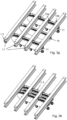
- the (first) drive unit 11 shown in Fig. 3a exhibits suspension elements 13, 13b of the kind described in Fig. 1a, 1b but without the electrical contacts. The electrical contacts being hidden in the remaining figures is for easier interpretation and clarity only.
- a first set of suspension elements 13 is facing in a first direction, while a second set of suspension elements 13b is facing in a second direction, opposite to the first direction.
- the (first) drive unit 11 comprises two circumferential tracks 12a, 12b for each set of suspension elements 13, 13b (i.e., in total four circumferential tracks), as described with respect to Fig. 2d-2m .
- the second housing 17 exhibiting the two circumferential tracks 12a, 12b for the second set of suspension elements 13b is hidden in Fig.
- FIG. 3b to show how the suspension elements 13, 13b can be connected to a common chain 15a (e.g., via pulleys 13.1 of both sets of suspension elements 13, 13b) which can be driven by a gear unit 18 connected to a motor 11.5.
- Fig. 3c and Fig. 3d show a further unit 16 (counter unit) guiding counter wheels 16.1 for also contacting profile units 1.1 from a "bottom" side with the same shape as the first drive unit 11.
- the counter wheels 16.1 alone cannot suspend/fix the crawler type vehicle 10.
- the counter wheels 16.1 only serve as a counter mechanism to push against the structure 1 to increase the force coupling between the suspension elements 13 and the structure 1.
- the counter wheels 16.1 also exhibit pulleys 16.2 via which they are pulled along two circumferential tracks to follow a predefined motion.
- Two (first) drive units 11 exhibiting two sets of suspension elements 13a, 13b respectively being arranged mirror-inverted to grasp a profile unit 1.1 from two sides, as well as two sets of counter wheels 16.1, are shown in Fig. 3e and Fig. 3f .
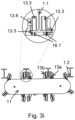
- the drive units from Fig. 3e and 3f are shown from a diagonally above perspective in Fig. 3g and Fig. 3h .
- the drive units 11 are connected to form a (first) drive arrangement 11.2 comprising two (first) drive units 11 and a counter unit 16.
- the drive arrangement 11.2 can be driven via a common shaft connected to the gear units 18 of the drive units 11 and counter unit 16 as shown in Fig. 3b and Fig. 3d .
- the mirror-inverted set of suspension element 13b is hidden behind the profile unit 1.1 in Fig. 3g and 3h . It is preferred to always have at least one set of mirror-inverted suspension elements 13b in order to enhance coupling security with the structure 1.
- the (first) drive units 11 from Fig. 3e and Fig. 3f form a first drive arrangement with a common motor 11.5 in Fig. 4a .
- an additional casing 14 is shown in Fig. 4b .
- the casing 14 exhibits the ball 14.2 of a ball joint 14.1 in the center of the drive arrangement (both in first (x) and second (y) direction).
- the (first) drive units 11a, 11b of the first drive arrangement 11.2 of course need some flexibility even though they are very close together in order to follow curved profile units 1.1.
- a short splined shaft with a universal joint can exemplarily be used to account for the small changes in angle between the (first) drive units 11 (of one first drive arrangement) when the vehicle 10 is following curved profile units 1.1 (in first spatial direction (x)).
- Fig. 4c shows a crawler type vehicle 10 according to one embodiment.
- the crawler type vehicle 10 exhibits two arrangements 11.2 of the type shown in Fig. 4b . It is however also possible to only use one (first) drive unit 11 for each of the arrangements 11.2.
- the two casings 14 of the arrangements 11.2 are coupled via a ball joint 14.1.
- the ball joint 14.1 preferably connects to a framework 14.3 of the vehicle 10 as shown in Fig. 4d .
- the (first) drive units 11 of the two drive arrangements 11.2 are connected via a drive mechanism 11.1 comprising a splined shaft 11.3 with universal joints 11.4, a close-up view of which can be found in Fig. 4c .
- two holonomic wheelsets 90 are shown in Fig.
- a motor 91 engages in a differential 91.1 connected to the holonomic wheelsets 90.
- the motor 91 and the holonomic wheels 90 are connected to the vehicle framework 14.3 in the middle between the two drive arrangements 11.2.
- Fig. 4e shows the crawler type vehicle 10 from a side-view perspective (from the second spatial direction).
- Fig. 4f shows the suspension elements 13, 13b of the crawler type vehicle 10 clamping the profile unit 1.1.
- the holonomic wheelsets 90 can be pressed against the profile units 1.1 from the bottom side (side facing the vehicle) with an additional return mechanism 90.1 not shown here.
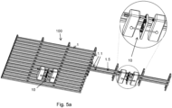
- Fig. 5a shows a first suspension arrangement 100 according to an embodiment.
- the suspension arrangement 100 comprises a structure 1 with a crawler type vehicle 10 suspended in the structure 1.
- a first conveyor/connector rail 1.5 leads out of the structure 1 e.g., to a further structure 1'.
- the first conveyor/connector rail 1' comprises two directly adjacent profile units 1.1.
- a second conveyor/connector rail 1.5 comprises two profile units 1.1 further spaced apart.
- the profile unit can be spaced apart any integer multiple of the pitch of the structural regularity 1a.
- Using profile units 1.1 further spaced apart for the conveyor/connector rail 1.5 can increase the stability of the crawler type vehicle 10 when driving along the conveyor/connector rail 1.5, especially in curved sections.
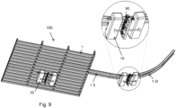
- Fig. 6 shows a further suspension arrangement 100 comprising a structure 1 and a crawler type vehicle 10 of the kind described in Fig. 4d to Fig. 4f .
- a conveyor/connector rail 1.5 describing a curve 1.5r leads out of the structure 1.
- a crawler type vehicle 10 driving along the curve 1.5r is also shown in a close-up view.
- the crawler type vehicle 10 is able to follow the curved conveyor/connector rail 1.5 due to the (first) drive units 11 (resp. the drive arrangements 11.2) being able to deviate from their original parallel orientation because of the ball joint 14.1 connecting the at least two (first) drive units (here connecting the casings 14 of the drive arrangements 11.2 comprising multiple drive units 11a, 11b and possibly also a counter unit 16).
- the crawler type vehicle 10 is able to move (or to be moved) in the first spatial direction (x) (right or left along the curved profile units) irrespective of momentary motion in second spatial direction (y).
- the orientation between the at least two drive units 11 (of the first kind) can change depending on the position of the vehicle in the structure 1' exhibiting the curved profile units 1.1, i.e., the farther out (with respect to the radius of the curve) the vehicle 10 is in the structure 1, the smaller is the angle between the orientations of the drive units (of the first kind).
- the details of a crawler type vehicle 10 following a curved conveyor/connector rail 1.5r is shown in Fig. 8 from a perspective view from diagonally above.
- the suspension elements 13 engage in the same manner with the profile units 1.1 as in Fig. 7 in the structure exhibiting the curved profile units 1.1.
- the suspension elements 13 of the (first) drive units 11 couple to the profile units 1.1 via the elements of motion 13.3 (preferably first wheel and side wheel (see Fig. 3i ), preferably from both sides of the profile unit 1.1 via mirror-inverted suspension elements 13 not shown here).
- the crawler type vehicle going upwards on the conveyor/connector rail 1.5 is shown in a perspective view from diagonally above.
- a close-up view further shows the return mechanism 90.1 applying a force onto the two holonomic wheelsets 90.
- the ball joints 14.1 of the crawler type vehicle 10 allow for the (first) drive units 11 to be tilted with respect to each other in any direction, i.e., not only left-right, but also up-down thus allowing the crawler type vehicle 10 to follow parallel profile units 1.1 going upwards/downwards, left/right as well as any combination thereof.
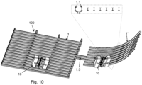
- Fig. 10 shows a further suspension arrangement 100 according to an embodiment.
- the suspension arrangement 100 exhibits two structures 1, 1' connected via a conveyor/connector rail 1.5 and two crawler type vehicles 10.
- One of the structures 1' exhibits curved profile units 1.1 describing a segment of a tube-like shape.
- the profile units 1.1 define the same structural regularity 1a in the second spatial direction (y) as before (see Fig. 3i ).
- the crawler type vehicle 10 is able to move (or to be moved) in the first spatial direction (x) (upwards or downwards the curved profile units) irrespective of momentary motion in second spatial direction (
- the described embodiments of the invention can be adapted to items to be stored with predefined upper and/or lower boundaries for their weight and/or size as well to handle stored items that can have different sizes, shapes and weights.
- the size and configuration of the ceiling arrangement and its components for lifting, transferring and lowering the items is partly predefined, especially by the dimension and strengths of profiles implemented in the structure.
- Other parts of the ceiling arrangement can be modified more easily, for example by providing vehicles with gripping units which are adapted to the items to be stored to the structure.
- the number of vehicles connected to the suspension structure can be modified.
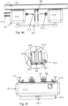
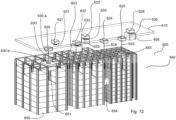
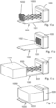
- Figures 12 , 13 , 14 show embodiments of storing arrangements according to the invention with a suspension arrangement located above stored items.
- the storing arrangement handles items according to the requirements of a logistics systems provider.
- the items can range from individual goods objects, via bins as examples of smaller containers to standardized containers up to intermodal containers and even intermodal containers that comply with ISO standards or suitable future standards.
- the storing arrangement is at least partly grid structured.
- Figures 12 , 13 , 14 show embodiments of storing arrangements according to the invention, wherein the items are arranged in stacks.
- items with similar base area are stacked upon each other.
- At least some stacks contain identical goods objects.
- the embodiment especially as shown in Figures 12 , 13 , 14 relates to the storage of goods in bins, which are stacked directly on top of each other and can be accessed and transported using vehicles and their gripping units.
- the automated storage and retrieval system contains a storing arrangement 640 which is at least partly grid-structured and wherein the suspension arrangement 610 is located above at least a part of the storing arrangement 640, wherein the crawler type vehicles 620, 621, 622, 623, 624, 625 and 626 can move above the at least one part of the storing arrangement 640 and wherein the vehicles 620, 621, 622, 623, 624, 625 and 626 each are equipped with at least one gripping unit 630, 631, 632, 633, 634, 635 and 636 for lifting items 650, 651, 652, 653, 654, 654, 655 and 656 from the storing arrangement to a position located above the storing arrangement 640.
- the top of the grid is an example of a transfer area for the items 650, 651, 652, 653, 654, 654, 655 and 656.
- lower position of the grid can also be used as part of a transfer area, especially by using long-reaching and/or long extendable gripping units 630, 631, 632, 633, 634, 635 and 636.
- At least two vehicles 620, 621, 622, 623, 624, 625 and 626 which can operate independently, especially move independently.
- a planar surface formed and defined by the at least two spatial directions of the suspending structure 610 is located in a distance from items 650, 651, 652, 653, 654, 654, 655 and 656 to be lifted and/or transported by the gripping unit of at least one of the one of the vehicles.
- At least one vehicle is a crawler type vehicle, especially as described in the previous figures, wherein the crawler type vehicle comprises means for providing for de-/coupling kinematics during a motion of the crawler type vehicle in said second spatial direction, especially with the crawler type vehicle being configured to be moved in said first spatial direction along the profile units irrespective of momentary motion in said second spatial direction enables independent movements of the vehicles with high acceleration, high speed and high deceleration.
- the design of the gripping units 630, 631, 632, 633, 634, 635 and 636 is influenced by the size, shape, weight, surface and material properties of the items 650, 651, 652, 653, 654, 654, 655 and 656 to be handled. Examples of gripping units which can be tailored to handle items are described in the current application text. It is especially useful to use gripping units gripping unit 630, 631, 632, 633, 634, 635 and 636 which consist of an elongator 630a, 631a, 632a, 633a, 634a, 635a, 636a and a gripper 630b, 631b, 632b, 633b, 633b, 635b, 636b.
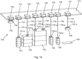
- Figure 13 and Figure 14 show a storing arrangement according to the invention with a suspension arrangement located above stored items.
- the storing arrangement handles items according to the requirements of a logistics systems provider.
- the items can range from individual goods objects, via bins as examples of smaller containers to standardized containers up to intermodal containers and even intermodal containers that comply with ISO standards or suitable future standards.
- the shown embodiment especially relates to the storage of goods on top of each other, preferably a stack of identical goods object, of any stackable good objects or of objects in bins, which are stacked directly on top of each other and can be accessed and transported using vehicles and their gripping units.
- the stacks can be positioned close to each other and/or separated by separation elements e.g. fences or nets to avoid/minimize a domino-effect in the highly improbable case of a mishandling of an item.
- separation elements e.g. fences or nets to avoid/minimize a domino-effect in the highly improbable case of a mishandling of an item.
- the automated storage and retrieval system contains a storing arrangement 740 wherein the suspension arrangement 710 is located above at least a part of the storing arrangement 740, wherein the crawler type vehicles 720, 721, 722, 723, 724, 725 and 727 can move above the at least one part of the storing arrangement 740 and wherein the vehicles 720, 721, 722, 723, 724, 725 and 727 each are equipped with at least one gripping unit 730, 731, 732, 733, 734, 735 and 737 for lifting items 750, 751, 752, 753, 754, 754, 755 and 757 from the storing arrangement to a position located above the storing arrangement 740.
- the top surface of the stacked items 751, 752, 753, 754 and 755 is an example of a transfer area for the items 751, 752, 753, 754 and 755 and the items below of these top-stacked items.
- At least two vehicles 720, 721, 722, 723, 724, 725 and 727 which can operate independently, especially move independently.
- At least two vehicles 723, 724 respectively at least two vehicles 723, 724, selected from a plurality 720, 721, 722, 723, 724, 725 and 727 of vehicles can be coordinated, especially by coordinating the movements of their gripping unit units for coordinated lifting and/or moving of a preferably heavier item.
- a planar surface formed and defined by the at least two spatial directions of the suspending structure 710 is located in a distance from items 750, 751, 752, 753, 754, 754, 755 and 757 to be lifted and/or transported by the gripping unit of at least one of the one of the vehicles 720, 721, 722, 723, 724, 725 and 727.
- At least one vehicle is a crawler type vehicle, especially as described in the previous figures, wherein the crawler type vehicle comprises means for providing for de-/coupling kinematics during a motion of the crawler type vehicle in said second spatial direction, especially with the crawler type vehicle being configured to be moved in said first spatial direction along the profile units irrespective of momentary motion in said second spatial direction enables independent movements of the vehicles with high acceleration, high speed and high deceleration.
- the design of the gripping units 730, 731, 732, 733, 734, 735 and 737 is influenced by the size, shape, weight, surface and material properties of the items 750, 751, 752, 753, 754, 754, 755 and 757 to be handled. Examples of gripping units which can be tailored to handle items are described in the current application text. It is especially useful to use gripping units gripping unit 730, 731, 732, 733, 734, 735 and 737 which each consist of an elongator 730a, 731a, 732a, 733a, 734a, 735a, 737a and a gripper 730b, 731b, 732b, 733b, 734b, 735b, 737b.
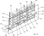
- Fig. 15 shows an automated storage and retrieval system, wherein the storing arrangement contains a plurality of storage positions accessible from at least one lateral side of the storing arrangement, wherein in each of the storage positions at least one item can be stored and wherein the suspension arrangement is located at least a lateral part of the storing arrangement, wherein the crawler type vehicle can move parallel to the at least one part of the storing arrangement and wherein the vehicle is equipped with at least one gripping unit for lifting items from the storing arrangement to a position located on the side of the storing arrangement.
- the storing arrangement according to Figure 15 the invention is equipped with a suspension arrangement located at the side of a storing arrangement, which in this embodiment is designed shelf-like.
- This example of an automated storage and retrieval system for the storing of items in a storing arrangement 940 is characterized in that the suspension arrangement for lifting, transferring and lowering the items is arranged parallel to at least one side of the shelf, which is described as a transfer area for the items.
- the open side of the shelf is an example of a transfer area for the items.
- the suspension arrangement 910 preferably comprises at least one structure (1, 1') extending in at least two spatial directions (x, y), wherein the structure (1, 1') comprises a plurality of profile units (1.1) extending in a first spatial direction (x), wherein the structure (1, 1') defines at least one structural regularity (1a) in a second spatial direction (y),
- Each of the shelves 941, 942, 943, 944, 945 and 946 contains a plurality of flexibly selectable storage positions accessible from at least one lateral side of the storing arrangement 940, wherein in each of the storage positions at least one item can be stored and wherein the suspension arrangement 910 is located towards at least a lateral part of the storing arrangement 940, wherein the vehicles 920, 921, 922, 923, 924 can move parallel to the at least one part of the storing arrangement 940 and wherein the vehicles 920, 921, 922, 923, 924 are equipped with at least one gripping unit 930, 931, 932, 9 for retrieving items from the storing arrangement 940 to a position located on the side of the storing arrangement and/or for storing items from outside the storing arrangement 940 into the storing arrangement 940.
- the automated storage and retrieval system according to Fig. 15 contains a storing arrangement 940 wherein the suspension arrangement 910 is located at a lateral side of at least a part of the storing arrangement 940, wherein the crawler type vehicles 920, 921, 922, 923, 924, 925 and 929 can move nearby but separated from the at least one part of the storing arrangement 940 and wherein the vehicles 920, 921, 922, 923, 924, 925 and 929 each are equipped with at least one gripping unit 930, 931, 932, 933, 934 for moving items 950, 951, 952, 953, 954, 954, 955, 956 and 957 between the storing arrangement 940 and a handling position located independently from the storing arrangement 940.
- At least two vehicles 920, 921, 922, 923, 924 which can operate independently, especially move independently.
- two or more vehicles 920, 921, 922, 923, 924 can operate independently implementations are possible and useful in which at least two vehicles respectively at least two vehicles, selected from a plurality 920, 921, 922, 923, 924 of vehicles can be coordinated, especially by coordinating the movements of their gripping unit units for coordinated lifting and/or moving of a preferably heavier item.
- a planar surface formed and defined by the at least two spatial directions of the suspending structure 910 is located in a distance from items 950, 951, 952, 953, 954, 954, 955, 956 to be lifted and/or transported by the gripping unit of at least one of the one of the vehicles 920, 921, 922, 923, 924.
- At least one vehicle is a crawler type vehicle, especially as described in the previous figures, wherein the crawler type vehicle comprises means for providing for de-/coupling kinematics during a motion of the crawler type vehicle in said second spatial direction, especially with the crawler type vehicle being configured to be moved in said first spatial direction along the profile units irrespective of momentary motion in said second spatial direction enables independent movements of the vehicles with high acceleration, high speed and high deceleration.
- the design of the gripping units 930, 931, 932, 933, 934, 935 and 939 is influenced by the size, shape, weight, surface and material properties of the items 950, 951, 952, 953, 954, 954, 955, 956 and 957 to be handled. Examples of gripping units which can be tailored to handle items are described in the current application text. It is especially useful to use gripping units 930, 931, 932, 933, 934, which are designed with extendable forks 930, 931, 932, 933, 934.
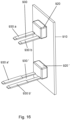
- Fig. 16 shows an example of a vehicle 920, 920' wherein the vehicle 920, 920' comprises a gripping unit 930, 930' wherein the gripping unit 930, 930' is configured to connect to at least one item; wherein the vehicle 920, 920' can move alongside a suspension arrangement which is configured for active motion of the vehicle, e.g., the suspension arrangement 910, depicted in Fig. 15 , in a first spatial direction and/or a second spatial direction.
- a suspension arrangement which is configured for active motion of the vehicle
- the gripping unit 930, 930' is equipped with extendable forks 930a, 930a', 930b, 930b'.
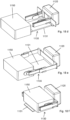
- Figs. 17a, 17b, 17c, 17d show an example of a vehicle 1020 wherein the vehicle 1020 comprises a gripping unit 1030 wherein the gripping unit is configured to connect to at least one item 1050; wherein the vehicle 1020 can move alongside a suspension arrangement which is configured for active motion of the vehicle, e.g., the suspension arrangement 910, depicted in Fig. 15 , in a first spatial direction and/or a second spatial direction.
- the gripping unit 1030 is equipped with a base element, e.g. a flat plate 1031 an extendable robotic arm 1033 and a gripper, e.g. a suction gripper 1032.
- a base element e.g. a flat plate 1031 an extendable robotic arm 1033 and a gripper, e.g. a suction gripper 1032.
- Fig. 17a shows a process step, wherein the base element, e.g. a flat plate 1031 is set, the extendable robotic arm 1033 is extended and the gripper, e.g. a suction gripper 1032 can be activated to grip an item.
- the base element e.g. a flat plate 1031
- the extendable robotic arm 1033 is extended and the gripper, e.g. a suction gripper 1032 can be activated to grip an item.
- Fig. 17b shows a process step, wherein the base element, e.g. a flat plate 1031 is set, the extendable robotic arm 1033 is retracted and the gripper, e.g. a suction gripper 1032 is retracted.
- the base element e.g. a flat plate 1031
- the gripper e.g. a suction gripper 1032
- Fig. 17c shows a process step, wherein the base element, e.g. a flat plate 1031 is set, the extendable robotic arm 1033 is extended and the gripper, e.g. a suction gripper 1032 is activated and grips an item 1050.
- the base element e.g. a flat plate 1031
- the extendable robotic arm 1033 is extended and the gripper, e.g. a suction gripper 1032 is activated and grips an item 1050.
- Fig. 17d shows a process step, wherein the base element, e.g. a flat plate 1031 is set, the extendable robotic arm 1033 is retracted and the gripper, e.g. a suction gripper 1032 is retracted to and has gripped the item 1050 an and wherein the retraction of the extendable robotic arm 1033 and the gripper 1032 has retracted the item 1050 from a storage position close to the vehicle 1020.
- the base element e.g. a flat plate 1031
- the gripper e.g. a suction gripper 1032
- Figs. 18a, 18b, 18c , 18d, 18e, 18f show an example of a vehicle 1120 wherein the vehicle 1120 comprises a gripping unit 1130 wherein the gripping unit 1130 is configured to connect to at least one item 1150; wherein the vehicle 1120 can move alongside a suspension arrangement which is configured for active motion of the vehicle, e.g., the suspension arrangement 910, depicted in Fig. 15 , in a first spatial direction and/or a second spatial direction.
- the gripping unit 1130 is equipped with a base element, e.g. a flat plate 1131, two extendable robotic arms 1133, 1134 capable of acting as a gripper that can be activated to grip an item 1150.
- a base element e.g. a flat plate 1131
- two extendable robotic arms 1133, 1134 capable of acting as a gripper that can be activated to grip an item 1150.
- Fig. 18a shows a process step, wherein the base element, e.g. a flat plate 1131 is set, the extendable robotic arms 1033 are retracted and moved close to each other.
- the base element e.g. a flat plate 1131
- the extendable robotic arms 1033 are retracted and moved close to each other.
- Fig. 18b shows a process step, wherein the base element, e.g. a flat plate 1131 is set, the extendable robotic arms 1133, 1134 are retracted and moved away from each other.
- the base element e.g. a flat plate 1131
- the extendable robotic arms 1133, 1134 are retracted and moved away from each other.
- Fig. 18c shows a process step, wherein the base element, e.g. a flat plate 1131 is set, the extendable robotic arms 1133, 1134 are extended/expanded and moved away from each other.
- the base element e.g. a flat plate 1131
- the extendable robotic arms 1133, 1134 are extended/expanded and moved away from each other.
- Fig. 18d shows a process step, wherein the base element, e.g. a flat plate 1131 is set, the extendable robotic arms 1033 are retracted and moved close to each other and where the vehicle 1120 is moved along the suspension arrangement so that the gripping unit 1130 has reached a position close to a storage position of the item 1150.
- the base element e.g. a flat plate 1131
- the extendable robotic arms 1033 are retracted and moved close to each other and where the vehicle 1120 is moved along the suspension arrangement so that the gripping unit 1130 has reached a position close to a storage position of the item 1150.
- Fig. 18e shows a process step, wherein the base element, e.g. a flat plate 1131 is set, the extendable robotic arms 1133, 1134 are extended/expanded and moved away from each other and gripping/holding the item 1150.
- the base element e.g. a flat plate 1131
- the extendable robotic arms 1133, 1134 are extended/expanded and moved away from each other and gripping/holding the item 1150.
- Fig. 18f shows a process step, wherein the base element, e.g. a flat plate 1131 is set, the extendable robotic arms 1133, 1134 are retracted and moved away from each other, gripping/holding the item 1150 and wherein the retraction of the extendable robotic arms 1133, 1134 has retracted the item 1150 from a storage position close to the vehicle 1120.
- the base element e.g. a flat plate 1131
- the extendable robotic arms 1133, 1134 are retracted and moved away from each other, gripping/holding the item 1150 and wherein the retraction of the extendable robotic arms 1133, 1134 has retracted the item 1150 from a storage position close to the vehicle 1120.
- the present application shows embodiments of a joint concept of carrying out processing operations on items as far as possible automatically and preferably also without contact.
- the present application further includes a handling of items with certain minimum dimensions, maximum dimensions, minimum weights and maximum weights as parcels, wherein the respective handling means are adapted to the reference quantities: Minimum dimensions, Maximum dimensions, Minimum weights and Maximum weights can be adapted.
- the parcels can be unpackaged objects, packaged objects and repackaged objects, whereby in the case of packaged and repackaged objects the parcel comprises the packaging or repackaging and the object packaged therein.
- unpackaged objects in particular commodity objects, according to the invention.
- parcel identification characteristics that are the same, in particular, and/or parcel identification characteristics that differ from other parcel identification characteristics may be used to identify a parcel.
- parcels in the sense of the present invention are always physical objects, in particular with constant physical properties, in particular weight and dimensions. It is thus possible, during the stay of the parcel in a logistics system according to the invention, to ensure that it is a specific parcel in each case. Different parcels usually differ in at least one physical property and can be distinguished from each other by measuring this physical property. These physical properties can therefore be used as parcel identification characteristics in an advantageous further embodiment of the invention.
- the parcel identification characteristic may also be, for example, a parcel identification code that uniquely identifies a parcel.
- a parcel identification code is applied to a parcel, for example, before it is handed over to a logistics system or a unit of the logistics system, for example, one of the receiving units shown in this application, for example, the storage facilities shown, or the parcel identification code is applied to the parcel during a delivery to the logistics system or one of the processing operations within the logistics system.
- Embodiments in which the parcel identification code is a physical code applied, for example, to the parcel, to an outer packaging of the parcel or to a storage unit for the parcel and/or a transport unit for the parcel and/or embodiments in which the parcel identification code is a digital code associated with the parcel and/or a digital twin of the parcel are also encompassed by the invention.
- control component of the logistics system can be designed in such a way that it controls as many or even all of the processing steps of the parcels as possible. However, it is also possible that the control component only controls individual process steps as described in this application.
- control component Details of preferred embodiments of the control component and its interaction with the components of the logistics system can be carried out as it is for example described in the international patent application WO 2022106598 .
- Another parameter is the suitability for storage of objects in the storage facility.
- Such items are also referred to as parcels in this application, even though they are not parcels in the classical sense.
- the items, respectively the parcels intended for handover are automatically identified, discharged, separated and transported e.g. via a conveyor belt to a handover position.
- robot tools are attached to the gripping unit arms preferably gripping units systems, in particular one or more suction pads, also called vacuum gripping units.
- gripping unit systems known from DE 198 17 426 A1 , in particular vacuum gripping unit systems, are adapted for this purpose.
- the gripping unit arms with one or more sensor modules, in particular at least one force sensor, to measure the force on the parcel to be lifted, in particular the parcels. Furthermore, it is advantageous to use position sensors that are suitable for measuring a relative position or a distance between the parcel and the gripping unit or for determining the start and end points of a movement.
- a flexible gripping device is used to pick up the items/parcels, which is illustrated for example in the European patent EP2042277B1 .
- This gripping device has a gripping unit with a multi-section frame, which is adapted for the present invention in such a way that better adaptation to variable dimensions (geometries) of the parcels is possible.
- a contactless logistics system is preferably provided in which the processing operations are carried out by machines so that the parcels and/or the objects contained in the parcels are protected from unwanted influences. Therefore, a complex outer packaging can be dispensed with.
Landscapes
- Engineering & Computer Science (AREA)
- Mechanical Engineering (AREA)
- Manufacturing & Machinery (AREA)
- Chemical & Material Sciences (AREA)
- Combustion & Propulsion (AREA)
- Transportation (AREA)
- Warehouses Or Storage Devices (AREA)
Priority Applications (2)
| Application Number | Priority Date | Filing Date | Title |
|---|---|---|---|
| EP23200953.0A EP4530226A1 (de) | 2023-09-29 | 2023-09-29 | Automatisiertes regalbediensystem; logistiksystem und verfahren zum handhaben mehrerer gegenstände |
| PCT/EP2024/077256 WO2025068485A1 (en) | 2023-09-29 | 2024-09-27 | Automated storage and retrieval system; logistics system and method for handling of a plurality of items |
Applications Claiming Priority (1)
| Application Number | Priority Date | Filing Date | Title |
|---|---|---|---|
| EP23200953.0A EP4530226A1 (de) | 2023-09-29 | 2023-09-29 | Automatisiertes regalbediensystem; logistiksystem und verfahren zum handhaben mehrerer gegenstände |
Publications (1)
| Publication Number | Publication Date |
|---|---|
| EP4530226A1 true EP4530226A1 (de) | 2025-04-02 |
Family
ID=88237523
Family Applications (1)
| Application Number | Title | Priority Date | Filing Date |
|---|---|---|---|
| EP23200953.0A Pending EP4530226A1 (de) | 2023-09-29 | 2023-09-29 | Automatisiertes regalbediensystem; logistiksystem und verfahren zum handhaben mehrerer gegenstände |
Country Status (2)
| Country | Link |
|---|---|
| EP (1) | EP4530226A1 (de) |
| WO (1) | WO2025068485A1 (de) |
Citations (11)
| Publication number | Priority date | Publication date | Assignee | Title |
|---|---|---|---|---|
| US4641757A (en) | 1983-05-06 | 1987-02-10 | Robotic Systems, Inc. | Circulating latch transport mechanism for overhead cranes |
| JPS62185631A (ja) * | 1986-02-10 | 1987-08-14 | Fuji Electric Co Ltd | 搬送装置 |
| DE19817426A1 (de) | 1998-04-18 | 1999-10-28 | Schmalz J Gmbh | Greifersystem, insbesondere Vakuumgreifersystem |
| US20100175943A1 (en) * | 2007-06-02 | 2010-07-15 | Bergmann Lars B | Storage or Conveying System |
| EP2042277B1 (de) | 2007-09-28 | 2010-12-08 | KUKA Systems GmbH | Flexibles Greifwerkzeug |
| US8628289B1 (en) * | 2003-05-06 | 2014-01-14 | Charles E. Benedict | Material handling and storage/warehouse system |
| DE202020100256U1 (de) * | 2020-01-17 | 2020-05-20 | MagneCat UG (haftungsbeschränkt) | Linearmotorisch angetriebenes Raupenfahrzeug |
| WO2022106598A1 (de) | 2020-11-20 | 2022-05-27 | Innovative Robot Delivery Gmbh | Verfahren, depoteinrichtung und system zur übergabe einer vielzahl von paketen an mehrere empfänger und/oder zur entgegennahme einer vielzahl von paketen von mehreren einlieferern |
| EP4134289A1 (de) * | 2020-04-27 | 2023-02-15 | Murata Machinery, Ltd. | Hängeträger und hängeträgersystem |
| WO2023073012A1 (de) | 2021-10-28 | 2023-05-04 | Innovative Robot Delivery Gmbh | Verfahren und übergabevorrichtung zur übergabe von warenobjekten |
| EP3803727B1 (de) | 2018-06-04 | 2023-07-26 | Celonis SE | Verfahren und system zum bereitstellen von prozessprotokollen für physische objekte |
Family Cites Families (1)
| Publication number | Priority date | Publication date | Assignee | Title |
|---|---|---|---|---|
| NO345665B1 (en) * | 2019-11-20 | 2021-06-07 | Autostore Tech As | A method, system and computer program for controlling an automated storage and retrieval system during rebuilding its physical design |
-
2023
- 2023-09-29 EP EP23200953.0A patent/EP4530226A1/de active Pending
-
2024
- 2024-09-27 WO PCT/EP2024/077256 patent/WO2025068485A1/en active Pending
Patent Citations (11)
| Publication number | Priority date | Publication date | Assignee | Title |
|---|---|---|---|---|
| US4641757A (en) | 1983-05-06 | 1987-02-10 | Robotic Systems, Inc. | Circulating latch transport mechanism for overhead cranes |
| JPS62185631A (ja) * | 1986-02-10 | 1987-08-14 | Fuji Electric Co Ltd | 搬送装置 |
| DE19817426A1 (de) | 1998-04-18 | 1999-10-28 | Schmalz J Gmbh | Greifersystem, insbesondere Vakuumgreifersystem |
| US8628289B1 (en) * | 2003-05-06 | 2014-01-14 | Charles E. Benedict | Material handling and storage/warehouse system |
| US20100175943A1 (en) * | 2007-06-02 | 2010-07-15 | Bergmann Lars B | Storage or Conveying System |
| EP2042277B1 (de) | 2007-09-28 | 2010-12-08 | KUKA Systems GmbH | Flexibles Greifwerkzeug |
| EP3803727B1 (de) | 2018-06-04 | 2023-07-26 | Celonis SE | Verfahren und system zum bereitstellen von prozessprotokollen für physische objekte |
| DE202020100256U1 (de) * | 2020-01-17 | 2020-05-20 | MagneCat UG (haftungsbeschränkt) | Linearmotorisch angetriebenes Raupenfahrzeug |
| EP4134289A1 (de) * | 2020-04-27 | 2023-02-15 | Murata Machinery, Ltd. | Hängeträger und hängeträgersystem |
| WO2022106598A1 (de) | 2020-11-20 | 2022-05-27 | Innovative Robot Delivery Gmbh | Verfahren, depoteinrichtung und system zur übergabe einer vielzahl von paketen an mehrere empfänger und/oder zur entgegennahme einer vielzahl von paketen von mehreren einlieferern |
| WO2023073012A1 (de) | 2021-10-28 | 2023-05-04 | Innovative Robot Delivery Gmbh | Verfahren und übergabevorrichtung zur übergabe von warenobjekten |
Also Published As
| Publication number | Publication date |
|---|---|
| WO2025068485A1 (en) | 2025-04-03 |
Similar Documents
| Publication | Publication Date | Title |
|---|---|---|
| AU2021278253B2 (en) | Multi-function inventory handling station assembly | |
| US10395152B2 (en) | Amassing pick and/or storage task density for inter-floor transfer | |
| CA2807675C (en) | Method and system for the automatic loading of air-transport units | |
| KR101895552B1 (ko) | 보충 및 주문 이행 시스템 | |
| US10029851B1 (en) | Routing based on automation capabilities in inventory system | |
| US20180186577A1 (en) | Mobile configurable conveyor component | |
| CA3235730A1 (en) | Automated product unloading, handling, and distribution | |
| CN109693903A (zh) | 一种货物装卸系统 | |
| AU2022364171B2 (en) | Systems and methods for order processing | |
| EP4530226A1 (de) | Automatisiertes regalbediensystem; logistiksystem und verfahren zum handhaben mehrerer gegenstände | |
| US12202673B1 (en) | Optimized replacement of sortation order receptacles | |
| US20250304386A1 (en) | Robotic package handling systems and methods | |
| JP7358690B2 (ja) | 仕分けステーション及びそれを備える物品集配システム | |
| EP4530145A1 (de) | Automatisierbares system zum transport von transportkabinen; logistiksystem und verfahren zum handhaben mehrerer kabinen | |
| US12330875B1 (en) | Storage, retrieval and order sortation arranged in vertical orientation | |
| WO2025193247A1 (en) | Storage, retrieval and order sortation arranged in vertical orientation | |
| JP2023133010A (ja) | 集品ステーション及びそれを備える物品集配システム | |
| WO2024196727A1 (en) | Warehousing system for storing and retrieving goods in containers |
Legal Events
| Date | Code | Title | Description |
|---|---|---|---|
| PUAI | Public reference made under article 153(3) epc to a published international application that has entered the european phase |
Free format text: ORIGINAL CODE: 0009012 |
|
| STAA | Information on the status of an ep patent application or granted ep patent |
Free format text: STATUS: THE APPLICATION HAS BEEN PUBLISHED |
|
| AK | Designated contracting states |
Kind code of ref document: A1 Designated state(s): AL AT BE BG CH CY CZ DE DK EE ES FI FR GB GR HR HU IE IS IT LI LT LU LV MC ME MK MT NL NO PL PT RO RS SE SI SK SM TR |
|
| TPAC | Observations filed by third parties |
Free format text: ORIGINAL CODE: EPIDOSNTIPA |
|
| STAA | Information on the status of an ep patent application or granted ep patent |
Free format text: STATUS: REQUEST FOR EXAMINATION WAS MADE |
|
| 17P | Request for examination filed |
Effective date: 20251001 |
|
| STAA | Information on the status of an ep patent application or granted ep patent |
Free format text: STATUS: EXAMINATION IS IN PROGRESS |