EP4530045A1 - Blasformeinheit für eine blasformanlage - Google Patents
Blasformeinheit für eine blasformanlage Download PDFInfo
- Publication number
- EP4530045A1 EP4530045A1 EP23200420.0A EP23200420A EP4530045A1 EP 4530045 A1 EP4530045 A1 EP 4530045A1 EP 23200420 A EP23200420 A EP 23200420A EP 4530045 A1 EP4530045 A1 EP 4530045A1
- Authority
- EP
- European Patent Office
- Prior art keywords
- blow
- interface
- blow mold
- media
- unit according
- Prior art date
- Legal status (The legal status is an assumption and is not a legal conclusion. Google has not performed a legal analysis and makes no representation as to the accuracy of the status listed.)
- Pending
Links
Images


Classifications
-
- B—PERFORMING OPERATIONS; TRANSPORTING
- B29—WORKING OF PLASTICS; WORKING OF SUBSTANCES IN A PLASTIC STATE IN GENERAL
- B29C—SHAPING OR JOINING OF PLASTICS; SHAPING OF MATERIAL IN A PLASTIC STATE, NOT OTHERWISE PROVIDED FOR; AFTER-TREATMENT OF THE SHAPED PRODUCTS, e.g. REPAIRING
- B29C49/00—Blow-moulding, i.e. blowing a preform or parison to a desired shape within a mould; Apparatus therefor
- B29C49/42—Component parts, details or accessories; Auxiliary operations
- B29C49/48—Moulds
- B29C49/4823—Moulds with incorporated heating or cooling means
-
- B—PERFORMING OPERATIONS; TRANSPORTING
- B29—WORKING OF PLASTICS; WORKING OF SUBSTANCES IN A PLASTIC STATE IN GENERAL
- B29C—SHAPING OR JOINING OF PLASTICS; SHAPING OF MATERIAL IN A PLASTIC STATE, NOT OTHERWISE PROVIDED FOR; AFTER-TREATMENT OF THE SHAPED PRODUCTS, e.g. REPAIRING
- B29C49/00—Blow-moulding, i.e. blowing a preform or parison to a desired shape within a mould; Apparatus therefor
- B29C49/42—Component parts, details or accessories; Auxiliary operations
- B29C49/48—Moulds
- B29C2049/4879—Moulds characterised by mould configurations
- B29C2049/4892—Mould halves consisting of an independent main and bottom part
-
- B—PERFORMING OPERATIONS; TRANSPORTING
- B29—WORKING OF PLASTICS; WORKING OF SUBSTANCES IN A PLASTIC STATE IN GENERAL
- B29C—SHAPING OR JOINING OF PLASTICS; SHAPING OF MATERIAL IN A PLASTIC STATE, NOT OTHERWISE PROVIDED FOR; AFTER-TREATMENT OF THE SHAPED PRODUCTS, e.g. REPAIRING
- B29C49/00—Blow-moulding, i.e. blowing a preform or parison to a desired shape within a mould; Apparatus therefor
- B29C49/42—Component parts, details or accessories; Auxiliary operations
- B29C49/56—Opening, closing or clamping means
- B29C2049/566—Locking means
-
- B—PERFORMING OPERATIONS; TRANSPORTING
- B29—WORKING OF PLASTICS; WORKING OF SUBSTANCES IN A PLASTIC STATE IN GENERAL
- B29C—SHAPING OR JOINING OF PLASTICS; SHAPING OF MATERIAL IN A PLASTIC STATE, NOT OTHERWISE PROVIDED FOR; AFTER-TREATMENT OF THE SHAPED PRODUCTS, e.g. REPAIRING
- B29C2949/00—Indexing scheme relating to blow-moulding
- B29C2949/07—Preforms or parisons characterised by their configuration
- B29C2949/0715—Preforms or parisons characterised by their configuration the preform having one end closed
-
- B—PERFORMING OPERATIONS; TRANSPORTING
- B29—WORKING OF PLASTICS; WORKING OF SUBSTANCES IN A PLASTIC STATE IN GENERAL
- B29C—SHAPING OR JOINING OF PLASTICS; SHAPING OF MATERIAL IN A PLASTIC STATE, NOT OTHERWISE PROVIDED FOR; AFTER-TREATMENT OF THE SHAPED PRODUCTS, e.g. REPAIRING
- B29C49/00—Blow-moulding, i.e. blowing a preform or parison to a desired shape within a mould; Apparatus therefor
- B29C49/02—Combined blow-moulding and manufacture of the preform or the parison
- B29C49/06—Injection blow-moulding
-
- B—PERFORMING OPERATIONS; TRANSPORTING
- B29—WORKING OF PLASTICS; WORKING OF SUBSTANCES IN A PLASTIC STATE IN GENERAL
- B29C—SHAPING OR JOINING OF PLASTICS; SHAPING OF MATERIAL IN A PLASTIC STATE, NOT OTHERWISE PROVIDED FOR; AFTER-TREATMENT OF THE SHAPED PRODUCTS, e.g. REPAIRING
- B29C49/00—Blow-moulding, i.e. blowing a preform or parison to a desired shape within a mould; Apparatus therefor
- B29C49/28—Blow-moulding apparatus
- B29C49/30—Blow-moulding apparatus having movable moulds or mould parts
- B29C49/36—Blow-moulding apparatus having movable moulds or mould parts rotatable about one axis
-
- B—PERFORMING OPERATIONS; TRANSPORTING
- B29—WORKING OF PLASTICS; WORKING OF SUBSTANCES IN A PLASTIC STATE IN GENERAL
- B29L—INDEXING SCHEME ASSOCIATED WITH SUBCLASS B29C, RELATING TO PARTICULAR ARTICLES
- B29L2031/00—Other particular articles
- B29L2031/712—Containers; Packaging elements or accessories, Packages
- B29L2031/7158—Bottles
Definitions
- the present invention relates to a blow molding unit for a blow molding system for forming plastic preforms into containers with a blow mold and a blowing device associated with the blow mold, wherein the blow mold is formed from a first and at least one second blow mold part, which can be pivoted relative to one another between the open and closed positions.
- the invention relates to a blow molding unit used in blow molding systems for the beverage industry, wherein beverage containers, in particular beverage bottles, are then formed from the preforms.
- blow molding units are usually arranged on a conveyor carousel, wherein, during the rotation of the conveyor carousel, the preforms are first inserted into the blow mold and then the interior of the preforms is pressurized with compressed air. By applying internal pressure, the walls of the preforms are pressed outwards into a blow cavity formed by the blow mold parts, which corresponds to the shape of the beverage bottles to be produced.
- a stretch rod can also be provided, which is successively inserted into the blow mold along the container axis and enables a certain axial elongation of the preforms.
- stretch blow molding Such a process is also referred to as stretch blow molding, and the systems are referred to as stretch blow molding systems.
- the blow molds consist of at least two blow mold parts, which together form a blow cavity. It is within the scope of the invention that the blow mold parts are each made in one piece or can be constructed in multiple parts, with a multi-part design comprising, in particular, a mold carrier and a format part arranged in the mold carrier, and the actual blow mold cavity being formed via the format part.
- a multi-part design comprising, in particular, a mold carrier and a format part arranged in the mold carrier, and the actual blow mold cavity being formed via the format part.
- blow mold parts are usually connected to one or more media supplies, whereby in the context of the invention, media means both fluid media and electrical media.
- media means both fluid media and electrical media.
- the neck ring is a protruding ring below an external thread of the preform, wherein the external thread is designed to accommodate a closure cap. Accordingly, this is an area that is already prefabricated and which should not be deformed during blow molding. This can be ensured by active cooling.
- the molds To enable such temperature control during blow molding, the molds must be connected to a media supply. After assembly, appropriate supply lines are attached to the blow mold parts, which are fixed during operation of the blow molding units. However, it should be noted that the frequent pivoting movement of the blow mold parts during opening and closing of the mold also subjects the lines to considerable stress, which means they must be checked at regular intervals and replaced if necessary.
- the object of the invention is to provide a blow molding unit which is characterized by lower maintenance requirements.
- blow molding unit according to patent claim 1. Accordingly, it is provided that the first and/or the second blow molding part is connected to a media supply via a media interface in the closed position and is decoupled from the media supply in the open position.
- the invention is based on the realization that it is not absolutely necessary to supply the blow mold with various media when the mold is open, particularly since the open state exists for a significantly shorter time interval compared to the closed state. This short time interval is generally not sufficient to cool the blow mold parts. As soon as the mold is returned to the closed state, the individual media are supplied again.
- Such a design can advantageously prevent the lines or hoses required for supply from being subjected to strong movements and thus stresses, since instead of a moving Media line, the media interface is completely decoupled.
- the invention is not limited to embodiments in which the blow mold is formed exclusively from two blow mold parts. Rather, according to a conventional embodiment, the invention also provides for at least three blow mold parts, one of which is designed as a base part. The assignment to the first or second blow mold part is freely selectable, so that the base part can represent a first or a second blow mold part.
- the media interface comprises a first interface part arranged on the first or second blow mold part, which can be connected to a second interface part connected to the media supply in the closed position. Accordingly, it is clear that the media interface is not formed exclusively in one blow mold part. Rather, it consists of at least two interface parts, which are located in the blow mold part on the one hand and assigned to the corresponding media supply on the other.
- the type of media interface and thus also the type of interface parts depend essentially on the type of medium.
- the media interface is designed as a fluid connection
- the first interface part connects to a fluid channel arranged in the first and/or second blow mold part.
- the media interface and thus also the interface parts are components intended to transfer a fluid between the media supply and the respective blow mold part.
- a fluid refers to any type of medium. which is in a gaseous and/or liquid state. In particular, this includes water, steam, or compressed air, whereby the type of fluid depends on the intended purpose, which is described in more detail below.
- a particularly preferred embodiment provides that the fluid channel connects to a media interface or a first interface part at both ends, so that at least two media interfaces are provided on the blow molded part.
- One of the media interfaces then enables a corresponding connection to the media supply.
- a connection to a return line of the media supply can be established via the second media interface.
- the blow molded part is supplied with a fluid via the media supply, so that one corresponding media interface is understood as the inlet to the blow molded part and the other media interface as the outlet.
- a temperature control device means a device that can actively temperature control, heat and/or cool a fluid.
- the blow molded part is supplied with a fluid via the inlet, which is accordingly designed as a temperature control fluid and which is removed via the other media interface after flowing through the fluid channel.
- the fluid is returned to the temperature control device, where it is then heated or cooled again.
- the temperature control fluid is preferably water or steam.
- Other fluids used for heating or cooling are also generally suitable as temperature control fluids.
- the fluid channel is open at an end opposite the media interface.
- the fluid channel is connected to the media supply at only one end, with no connection to another device being provided at the opposite end.
- the fluid can then be used to push the already completely formed preform or the beverage bottle out of the blow cavity.
- the fluid is preferably compressed air.
- the open end of the fluid channel can end either at the lateral blow mold parts or at a base part, so that the container is pushed out either laterally and/or upwards.
- the media supply is accordingly a compressed air supply and not a temperature control device.
- the at least one media interface is designed as a fluid connection
- the problem arises that when the media interface or the interface parts are decoupled from one another, the respective fluid can still enter the blow mold because the second interface part continues to be supplied with a fluid via the media supply.
- a design is disadvantageous, particularly in connection with a temperature control fluid, so that a preferred development of the invention provides that the first and/or the second interface part is designed to be fluid-tight in the open position.
- a fluid-tight design means that the fluid channel within the blow mold part or any connections of the media supply to the second interface part are closed to the outside, so that no fluid can escape from the blow mold parts or from the media supply.
- first and/or the second interface part contains a valve body which is designed to be closed in the open position and opened in the closed position of the blow mold part.
- a valve body which is designed to be closed in the open position and opened in the closed position of the blow mold part.
- such a design can also be useful in combination with the first interface part, especially if it is intended to prevent residual fluid from escaping from the fluid channels of the blow-molded part.
- At least one media interface is designed as an electrical connection, wherein the first interface part connects to at least one electronic consumer on or in the first and/or the second blow mold part.
- electrical current or an electrical signal can thus be transmitted via the media interface.
- the electrical connection is a connection of electrical conductors which can be coupled to one another via the media interface.
- a media interface is not limited to merely to connect a conductor.
- the media interface or electrical connection can also enable the coupling of multiple conductors or wires.
- Such a configuration can be used for various applications, with a preferred configuration providing that the electrical load is a temperature control device and/or a measuring device.
- the electrical load is a temperature control device and/or a measuring device.
- the temperature control device is arranged outside the blow mold and serves to control the temperature of a temperature control fluid.
- This temperature control fluid is then fed to a blow molded part via the media interface, with the temperature control fluid in the fluid channels causing heating or cooling of the blow molded part.
- the temperature control device can also be at least one heating coil, which heats up due to its electrical resistance when a voltage is applied. Accordingly, these heating coils arranged in the blow mold part are coupled to a media supply or power supply via the electrical connection and enable heating of the corresponding blow mold part when the mold is closed.
- Such a design has the advantage over previous solutions that the heating coils are safely disconnected from the power supply when the mold is open, thus ensuring a high degree of safety for the user even in the event of any damage to the insulation.
- unlike designs with a temperature control fluid there is no need to separately ensure that the fluid channels are sealed to the outside when the mold is open in order to prevent the temperature control fluid from escaping.
- a measuring device can comprise a variety of possible measuring sensors or be designed accordingly as a measuring sensor.
- This measuring sensor can, for example, be a temperature sensor that detects the temperatures of the blow mold parts. Alternatively, it can also be simple measuring sensors that detect the closed or open state of the blow mold.
- the interface parts are designed as plug-in connections.
- the first or second interface part is designed as a male connector
- the other interface part is designed as a female connector, so that they can engage with each other in the closed state to enable electrical contact.
- spring-loaded pins can also be used, which are attached to contact plates.
- a further development of the invention provides that the interconnectable interface parts of at least one media interface are arranged on the first and second blow mold parts.
- one of the blow mold parts then has the first interface, and the other blow mold part has the second interface part, so that media transfer occurs between the blow mold parts.
- one blow mold part is preferably firmly connected to the media supply, while another blow mold part is coupled to the media supply via the other blow mold part.
- the second blow mold part can be firmly coupled to the media supply in both an open and a closed state, while the first blow mold part can only be via which the second blow molded part is coupled to the media supply.
- a stationary design means that the second blow mold part does not actively participate in the pivoting movement. Rather, the opening and closing of the blow mold takes place solely via a pivoting movement of the first blow mold part. Based on this, the first interface part of at least one media interface can then be arranged on the first blow mold part. The second interface part is then preferably formed accordingly on the second blow mold part.
- a corresponding media interface for the second blow mold part is not subject to the particularly high loads during a pivoting movement, so that the connection of the second blow mold part to the media supply can be made in a known, permanently installed manner.
- blow mold parts can be locked together in the closed position via at least one locking device.
- a locking device makes it possible to prevent the blow mold parts from pivoting apart. This is particularly important during the blow molding process.
- Such a locking device preferably not only allows the blow molds to pivot apart but also to lock them together. Locking means that the blow mold parts are pressed together with a specific pressure.
- the locking device not only This not only provides a locking mechanism but also simultaneously couples the interface components to one another.
- the media interfaces it is also within the scope of the invention for the media interfaces to be separated from the locking device and, for example, arranged next to it.
- connection block connected to the media supply is provided with at least one second interface part, wherein the first and/or the at least second blow mold part are each connected to the connection block in the closed position via a first interface.
- first and/or the at least second blow mold part are each connected to the connection block in the closed position via a first interface.
- both blow mold parts are designed to be pivotable, so that both blow mold parts can then be pivoted against this connection block and the corresponding interface parts are coupled to one another.
- one blow mold part is designed to be stationary, in which case the first or the second interface part is designed as a base part.
- the connection block can preferably be mounted on the stationary blow mold part or separately on the blow molding unit.
- the invention further relates to a blow molding system with at least one blow molding unit according to the invention, wherein the at least one blow molding unit is arranged on a rotatably driven carrier.
- a drive device which effects a closing movement and an opening movement between the blow mold parts.
- the drive device is preferably a cam-controlled drive device, so that the movement is effected solely on the basis of the Rotation of the blow molding units on the rotatably driven carrier is effected.
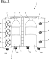
- the Fig. 1 shows a blow mold 1 for a blow molding unit of a blow molding system for forming plastic preforms into beverage containers.
- the blow molding unit additionally has a blowing device (not shown) via which the blow mold 1 or a preform arranged in the blow mold 1 can be subjected to compressed air, so that a beverage container, in particular a beverage bottle, can be formed from it.
- the blow mold 1 consists of a first and a second blow mold part 2, 3, each of which has a molding 4 for the joint formation of a blow cavity 5.
- This blow cavity 5 essentially corresponds to the shape of the container to be manufactured.
- the two blow mold parts 2, 3 are also pivotable relative to each other via a pivot axis S, so that the blow mold 1 can be moved between an open and a closed position.
- Fig. 1 In this context, the opening position of the blow mold 1 is shown.
- blow molding unit and thus also the blow mold 1
- a rotatable support also not shown in detail
- the preforms are formed into beverage containers during rotating transport on the support.
- This requires the blow mold parts 2, 3 to pivot toward or away from each other at defined angular positions.
- the preforms are inserted in the open position shown.
- This contact surface 6 defines a parting plane between the blow mold parts 2, 3, in which they must be pressed together using a sufficiently large contact force so that a clean forming of the preforms can take place along this parting plane.
- locking devices 7 are provided, by means of which the blow mold parts 2, 3 are locked together and pressed together in the closed position.
- These locking devices 7 each consist of a chuck 8 and an associated clamping bolt 9, wherein the chuck 7 is located in the first blow mold part 2 and the clamping bolts 9 in the second blow mold part 3. During the closing movement, the clamping bolts 9 are then each inserted into an opening of the associated chuck 7 and held there.
- media interfaces 10a, 10b are also provided, via which fluid channels formed in the blow mold parts 2, 3 are coupled to a media supply.
- the media supply is a fluid supply, e.g., of a temperature control device, to which a temperature-controlled fluid or a temperature control fluid is provided.
- This temperature control fluid flows via the media interfaces 10a into the respective blow mold part 2, 3 and out again via the media interface 10b.
- the media interfaces 10a, 10b are usually firmly connected to the media supply during assembly, so that the lines connected to them move along during the pivoting movement.
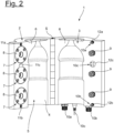
- Fig. 2 an embodiment according to the invention in which only the second blow mold part 3 is formed with fixed media interfaces 10a, 10b, 10c, wherein the media interface 10c, in contrast to the media interfaces 10a, 10b, is formed as an electrical connection and thus enables the transmission of an electrical signal.
- the media interfaces 10a, 10b, 10c each consist of a first interface part 11a, 11b and a second interface part 12a, 12b, which couple the media interfaces 10a, 10b to a media supply in the closed position and in the open position from the Decouple the media supply, whereby in this context reference is made exclusively to the first blow mold part 2.
- the interface parts 11a, 11b, 12a, 12b are correspondingly connected to fluid channels within the blow mold parts 2, 3, whereby in the closed position the fluid, e.g. a temperature control fluid, is then transferred via the interface parts 11a, 12a to the first blow mold part 2 and returned via the interface parts 11b, 12b to the second blow mold part.
- the interface parts 12a, 12b are designed to be fluid-tight to the outside in an open position, so that no fluid can escape from the blow-molded part 3 in an open position.
- the first interface parts 11a, 11b can also be designed to be fluid-tight.
- first blow mold part 2 also has a first interface part 11c and the second blow mold part has a second interface part 12c, via which electrical contact is made possible.
- This electrical contact is designed as a plug connection, with the male pins of the second interface part 12c engaging in receptacles of the first interface part 11c.
- the first interface part 11c is also integrated into a locking device 7 or into the chuck 8.
- the Fig. 3 shows a configuration with a total of three blow mold parts 2, 3, 13, wherein in this case the second blow mold part 3 is designed as a base part.
- the locking devices 7 then act between the first blow mold part 2 and the third blow mold part 13, wherein the clamping bolts 9 in this case are in the first blow mold part 2 and the clamping chucks 8 in the third blow mold part 13 are arranged.
- the second blow mold part 3 is pivoted relative to the first and third blow mold parts 2, 13, with the second blow mold part 3 having fixed media connections 10a, 10b.
- the first and third blow mold parts 2, 13 are then connected in such a way that the second blow mold part 3 has a total of four first interface parts 11a, 11b, each of which engages in associated second interface parts 12a, 12b in the first and third blow mold parts 2, 13.
- the Figure 4 shows a blow mold 1 according to the invention with a connection block 14, wherein the connection block 14 has a second interface part 12c on both sides as part of a media interface 10c, and via which electrical data can be transmitted.
- first interface parts 11c are provided on the first and second blow mold parts 2, 3, which according to the Figure 4 in the closed position interact with the second interface parts 12c and wherein the media interfaces 10c are designed as plug connections.
Landscapes
- Engineering & Computer Science (AREA)
- Manufacturing & Machinery (AREA)
- Mechanical Engineering (AREA)
- Moulds For Moulding Plastics Or The Like (AREA)
- Blow-Moulding Or Thermoforming Of Plastics Or The Like (AREA)
Abstract
Description
- Die vorliegende Erfindung betrifft eine Blasformeinheit für eine Blasformanlage zum Umformen von Vorformlingen aus Kunststoff zu Behältern mit einer Blasform und einer der Blasform zugeordneten Blaseinrichtung, wobei die Blasform aus einem ersten und zumindest einem zweiten Blasformteil gebildet ist, welche zwischen Öffnungs- und Schließstellung zueinander verschwenkbar sind.
- Im Besonderen bezieht sich die Erfindung auf eine Blasformeinheit, welche in Blasformanlagen für die Getränkeindustrie eingesetzt werden, wobei dann aus den Vorformlingen Getränkebehälter, insbesondere Getränkeflaschen, gebildet werden. Derartige Blasformeinheiten sind üblicherweise an einem Transportkarussell angeordnet, wobei während der Rotation des Transportkarussells die Vorformlinge zunächst in die Blasform eingesetzt werden und anschließend der Innenraum der Vorformlinge mit Druckluft beansprucht wird. Durch das Einbringen eines Innendruckes werden die Wandungen der Vorformlinge nach außen in eine von den Blasformteilen gebildete Blaskavität gedrückt, welche der Form der zu fertigenden Getränkeflaschen entspricht. Zusätzlich kann auch eine Reckstange vorgesehen sein, welche sukzessive entlang der Behälterachse in die Blasform eingefahren wird und eine gewisse axiale Längung der Vorformlinge ermöglicht. Ein solches Verfahren wird auch als Streck-Blasformen bzw. die Anlagen als Streck-Blasanlagen bezeichnet.
- Wie eingangs erläutert, bestehen die Blasformen aus zumindest zwei Blasformteilen, welche gemeinsam eine Blaskavität bilden. Hierbei liegt es im Rahmen der Erfindung, dass die Blasformteile jeweils einteilig oder aber auch mehrteilig ausgebildet sein können, wobei bei einer mehrteiligen Ausbildung insbesondere ein Formträger und ein in dem Formträger angeordnetes Formatteil vorgesehen ist und wobei dann über das Formatteil die eigentliche Blaskavität ausgebildet wird. Dies hat den Vorteil, dass für unterschiedliche Behältertypen lediglich das Formatteil nicht aber die gesamte Blasform ausgetauscht werden muss, sodass sich ein deutlich reduzierter Montageaufwand ergibt. Die eigentliche Verstellung bzw. Verschwenkung der einzelnen Blasformteile wird dann über die Formatträger bewirkt.
- Hierbei ist zu beachten, dass die Blasformteile üblicherweise an eine oder mehrere Medienversorgungen angeschlossen sind, wobei im Rahmen der Erfindung mit Medien sowohl fluide Medien als auch elektrische Medien gemeint sind. So ist es beispielsweise möglich, die Blasformen, insbesondere die Formatteile, während des Betriebs zu temperieren bzw. aktiv zu erwärmen oder zu kühlen. Durch ein Erwärmen soll insbesondere verhindert werden, dass die Vorformlinge sich an einigen Stellen zu schnell abkühlen, sodass es dann schwieriger wird, die Vorformlinge auszuformen. Gleichzeitig können so auch Spannungen innerhalb des Materials verhindert bzw. verringert werden. Eine Kühlung kann insbesondere im Bereich eines sogenannten Neckringes vorgesehen sein. Bei dem Neckring handelt es sich um einen vorstehenden Ring unterhalb eines Außengewindes des Vorformlings, wobei das Außengewinde zur Aufnahme einer Verschlusskappe ausgebildet ist. Entsprechend handelt es sich um einen Bereich, welcher bereits vorgefertigt ist und welcher im Zuge des Blasformens nicht verformt werden soll. Dies kann über eine aktive Kühlung gewährleistet werden.
- Um eine solche Temperierung während des Blasformens zu ermöglichen, müssen die Blasformen mit einer Medienversorgung verbunden werden. Hierzu werden an den Blasformteilen nach der Montage entsprechende Versorgungsleitungen befestigt, welche während des Betriebes der Blasformeinheiten festgelegt sind. Hierbei ist allerdings zu beachten, dass durch die häufige Schwenkbewegung der Blasformteile im Zuge des Öffnens und Schließens der Blasform auch die Leitungen starken Belastungen ausgesetzt werden, welche dazu führen, dass diese in regelmäßigen Abständen überprüft und gegebenenfalls ausgetauscht werden müssen.
- Vor diesem Hintergrund liegt der Erfindung die Aufgabe zugrunde, eine Blasformeinheit anzugeben, welche sich durch einen geringeren Wartungsaufwand auszeichnet.
- Gegenstand und Lösung dieser Aufgabe ist eine Blasformeinheit gemäß Patentanspruch 1. Demnach ist vorgesehen, dass das erste und/oder das zweite Blasformteile über eine Medienschnittstelle in der Schließstellung mit einer Medienversorgung verbunden und in der Öffnungsstellung von der Medienversorgung entkoppelt ist.
- Die Erfindung geht von der Erkenntnis aus, dass es während des Öffnungszustandes der Blasform nicht zwingend erforderlich ist, die Blasform mit verschiedenen Medien zu versorgen, insbesondere da der Öffnungszustand im Verhältnis zum Schließzustand für ein wesentlich kürzeres Zeitintervall vorliegt. Dieses kurze Zeitintervall ist in der Regel nicht ausreichend, um eine Auskühlung der Blasformteile zu bewirken. Sobald die Blasform wieder in den Schließzustand überführt wird, erfolgt auch erneut eine Zuführung der einzelnen Medien. Durch eine solche Ausbildung kann in vorteilhafter Art und Weise vermieden werden, dass die zur Versorgung erforderlichen Leitungen oder Schläuche starken Bewegungen und damit Belastungen unterliegen, da anstelle einer bewegten Medienleitung, die Medienschnittstelle vollständig entkoppelt wird.
- In diesem Zusammenhang ist anzumerken, dass die Erfindung nicht nur auf Ausgestaltungen begrenzt ist, bei der die Blasform ausschließlich aus zwei Blasformteilen gebildet ist. Vielmehr sieht die Erfindung gemäß einer üblichen Ausgestaltung auch vor, dass zumindest drei Blasformteile vorgesehen sind, von denen ein Blasformteil als Bodenteil ausgebildet ist. Die Zuordnung zum ersten oder zum zweiten Blasformteil erfolgt hierbei in freier Art und Weise, sodass das Bodenteil ein erstes oder ein zweites Blasformteile darstellen kann.
- Gemäß einer bevorzugten Ausgestaltung der Erfindung weist die Medienschnittstelle ein an dem ersten oder dem zweiten Blasformteil angeordnetes erstes Schnittstellenteil auf, welches mit einem mit der Medienversorgung verbundenen zweiten Schnittstellenteil in der Schließstellung verbindbar ist. Entsprechend wird deutlich, dass die Medienschnittstelle nicht ausschließlich in einem Blasformteil gebildet ist. Vielmehr besteht es aus zumindest zwei Schnittstellenteilen, welche einerseits in dem Blasformteil und andererseits der entsprechenden Medienversorgung zugeordnet werden. Die Art der Medienschnittstelle und damit auch die Art der Schnittstellenteile richten sich im Wesentlichen nach Art des Mediums.
- So sieht eine bevorzugte Ausgestaltung vor, dass die Medienschnittstelle als Fluidanschluss ausgebildet ist und das erste Schnittstellenteil an eine in dem ersten und/oder zweiten Blasformteil angeordneten Fluidkanal anschließt. Entsprechend handelt es sich bei der Medienschnittstelle und damit auch bei den Schnittstellenteilen um Bauteile, welche dazu vorgesehen sind, ein Fluid zwischen der Medienversorgung und dem jeweiligen Blasformteil zu übertragen. Mit einem Fluid ist in diesem Zusammenhang jedwede Art von Medium gemeint, welches in einem gasförmigen und/oder flüssigen Zustand vorliegt. Insbesondere handelt es sich hierbei um Wasser, Wasserdampf oder Druckluft, wobei sich die Art des Fluids an dem zu beabsichtigten Zweck orientiert, welcher nachfolgend näher dargestellt wird.
- So sieht beispielsweise eine besonders bevorzugte Ausgestaltung vor, dass der Fluidkanal an beiden Enden an eine Medienschnittstelle bzw. an ein erstes Schnittstellenteil anschließt, sodass entsprechend zumindest zwei Medienschnittstellen an dem Blasformteil vorgesehen sind. Hierbei ermöglicht dann eine der Medienschnittstellen eine entsprechende Ankopplung an die Medienversorgung. Über die zweite Medienschnittstelle kann eine Koppelung mit einem Rücklauf der Medienversorgung erfolgen. Alternativ ist es aber auch möglich die zweite Medienschnittstelle mit einer anderweitigen Vorrichtung zu verbinden.
- Die Idee dahinter besteht darin, dass mittels der Medienversorgung das Blasformteil mit einem Fluid versorgt wird, sodass eine entsprechende Medienschnittstelle als Zulauf zum Blasformteil und die jeweils andere Medienschnittstelle als Ablauf verstanden wird. Eine solche Ausgestaltung kann insbesondere sinnvoll sein, wenn der Fluidkanal in der Schließstellung an eine Temperiervorrichtung anschließt. Mit einer Temperiervorrichtung ist in diesem Zusammenhang eine Vorrichtung gemeint, welche aktiv ein Fluid temperieren bzw. erwärmen und/oder kühlen kann. Eine solche Temperiervorrichtung wurde bereits eingangs erwähnt und dargestellt, in welchem Zusammenhang eine aktive Kühlung oder Erwärmung der Blasformteile sinnvoll ist. Über den Zulauf wird das Blasformteil mit einem Fluid versorgt, welches entsprechend als Temperierfluid ausgebildet ist und welche es nach Durchströmen des Fluidkanals über die andere Medienschnittstelle entnommen wird.
- Bevorzugt ist vorgesehen, dass eine Rückführung in die Temperiervorrichtung erfolgt, in welcher dann eine erneute Erwärmung oder Abkühlung des Temperierfluids durchgeführt wird. Bei dem Temperierfluid handelt es sich in einem solchen Fall bevorzugt um Wasser oder Wasserdampf. Selbstverständlich ist es aber auch möglich ein Mischfluid aus Wasser und Wasserdampf vorzusehen. Auch anderweitige Fluide, welche der Erwärmung oder Kühlung dienen, sind grundsätzlich als Temperierfluid geeignet.
- Eine alternative Ausgestaltung sieht vor, dass der Fluidkanal an einem der Medienschnittstelle gegenüber liegenden Ende offen ist. Gemäß einer solchen Ausgestaltung ist der Fluidkanal entsprechend nur an einem Ende mit der Medienversorgung verbunden, wobei an dem gegenüberliegenden Ende keine Anbindung an eine weitere Vorrichtung vorgesehen ist. Eine solche Ausgestaltung ist insbesondere dann sinnvoll, wenn das offene Ende des Fluidkanals in einem die Blaskavität bildenden Abschnitt der Blasformteile angeordnet ist. Ausgehend von einer solchen Ausgestaltung kann dann das Fluid dazu genutzt werden, den bereits fertig umgeformten Vorformling bzw. die Getränkeflasche aus der Blaskavität herauszudrücken. Entsprechend handelt es sich bei dem Fluid vorzugsweise um Druckluft. Das offene Ende des Fluidkanals kann sowohl an den seitlichen Blasformteilen als auch an einem Bodenteil enden, so dass der Behälter entweder seitlich und/oder nach oben herausgedrückt wird. Bei der Medienversorgung handelt es sich entsprechend um eine Druckluftversorgung und nicht um eine Temperiervorrichtung.
- Sofern die zumindest eine Medienschnittstelle als Fluidanschluss ausgebildet ist, ergibt sich die Problematik, dass bei einer Entkopplung der Medienschnittstelle bzw. einer Entkopplung der Schnittstellenteile miteinander das jeweilige Fluid dennoch in die Blasform eintreten kann, da das zweite Schnittstellenteil weiterhin über die Medienversorgung mit einem Fluid versorgt wird. Gerade im Zusammenhang mit einem Temperierfluid ist eine solche Ausgestaltung jedoch von Nachteil, sodass eine bevorzugte Weiterbildung der Erfindung vorsieht, dass das erste und/oder das zweite Schnittstellenteil in der Öffnungsstellung fluiddicht ausgebildet ist. Mit einer fluiddichten Ausbildung ist in diesem Zusammenhang gemeint, dass der Fluidkanal innerhalb des Blasformteils oder aber auch etwaige Anschlüsse der Medienversorgung an das zweite Schnittstellenteil nach außen hin geschlossen sind, sodass kein Fluid aus den Blasformteilen oder aus der Medienversorgung austreten kann. Dies kann beispielsweise dadurch bewirkt werden, dass das erste und/oder das zweite Schnittstellenteil einen Ventilkörper beinhaltet, welcher dazu eingerichtet ist, in der Öffnungsstellung geschlossen und in der Schließstellung des Blasformteiles geöffnet zu werden. Grundsätzlich reicht es im Rahmen der Erfindung aus, wenn ein entsprechender Ventilkörper an dem zweiten Schnittstellenteil gebildet ist. Allerdings kann auch in Kombination mit dem ersten Schnittstellenteil eine solche Ausgestaltung sinnvoll sein, insbesondere wenn verhindert werden soll, dass Restfluid aus den Fluidkanälen des Blasformteils austritt.
- Eine Weiterbildung der Erfindung sieht vor, dass alternativ oder in Kombinationen zumindest eine Medienschnittstelle als elektrischer Anschluss ausgebildet ist, wobei das erste Schnittstellenteil an zumindest einen elektronischen Verbraucher an oder in dem ersten und/oder dem zweiten Blasformteil anschließt. Gemäß einer solchen Ausgestaltung kann somit über die Medienschnittstelle elektrischer Strom bzw. ein elektrisches Signal übermittelt werden. Entsprechend handelt es sich bei dem elektrischen Anschluss um einen Anschluss von elektrischen Leitern, welche über die Medienschnittstelle miteinander gekoppelt werden können. Hierbei ist eine Medienschnittstelle nicht darauf beschränkt, lediglich einen Leiter zu verbinden. Grundsätzlich kann die Medienschnittstelle bzw. der elektrische Anschluss auch eine Koppelung mehrerer Leitern bzw. Adern ermöglichen.
- Eine solche Ausgestaltung kann für verschiedene Anwendungszwecke genutzt werden, wobei eine bevorzugte Ausgestaltung vorsieht, dass der elektrische Verbraucher eine Temperiervorrichtung und/oder eine Messeinrichtung ist. Bereits zuvor wurde auf eine Temperiervorrichtung hingewiesen, wobei in diesem Zusammenhang die Temperiervorrichtung außerhalb der Blasform angeordnet ist und dazu dient, ein Temperierfluid zu temperieren. Dieses Temperierfluid wird dann über die Medienschnittstelle einem Blasformteil zugeführt, wobei über das Temperierfluid in den Fluidkanälen eine Erwärmung oder Abkühlung des Blasformteils bewirkt wird.
- Alternativ kann es sich bei der Temperiervorrichtung aber auch um zumindest eine Heizwendel handeln, welche sich aufgrund ihres elektrischen Widerstandes bei Anliegen einer Spannung erwärmt. Entsprechend werden diese in dem Blasformteil angeordneten Heizwendeln über den elektrischen Anschluss mit einer Medienversorgung bzw. Stromversorgung gekoppelt und ermöglichen in einem Schließzustand der Blasform eine Erwärmung des entsprechenden Blasformteils. Eine solche Ausgestaltung weist gegenüber den bisherigen Lösungen den Vorteil auf, dass in einem Öffnungszustand die Heizwendeln sicher von der Stromversorgung getrennt sind und so auch bei etwaigen Beschädigungen der Isolation stets ein hohes Maß an Sicherheit für den Anwender gewährleistet ist. Zugleich muss gegenüber Ausgestaltungen mit einem Temperierfluid nicht separat sichergestellt werden, dass die Fluidkanäle nach außen hin in einem Öffnungszustand der Blasform abgedichtet werden, um einen Austritt des Temperierfluids zu vermeiden.
- Eine Messvorrichtung kann eine Vielzahl möglicher Messsensoren umfassen oder entsprechend als Messsensor ausgebildet sein. Bei diesem Messsensor kann es sich beispielsweise um einen Temperaturfühler handeln, welcher die Temperaturen der Blasformteile erfasst. Alternativ kann es sich auch um einfache Messsensoren handeln, welche den Schließzustand oder den Öffnungszustand der Blasform erfassen.
- Ausgehend von einer solchen Ausgestaltung ist bevorzugt vorgesehen, dass die Schnittstellenteile als Steckverbindung ausgebildet sind. Hierbei ist dann das erste oder das zweite Schnittstellenteil in männlicher und das jeweils andere Schnittstellenteil in weiblicher Art und Weise ausgebildet, sodass diese in dem Schließzustand ineinander eingreifen können, um eine elektrische Kontaktierung zu ermöglichen. Alternativ können auch federbelastete Pins zum Einsatz kommen, welche auf Kontaktplatten befestigt werden.
- Eine Weiterbildung der Erfindung sieht vor, dass die miteinander verbindbaren Schnittstellenteile zumindest einer Medienschnittstelle an dem ersten und dem zweiten Blasformteil angeordnet sind. Gemäß einer solchen Ausgestaltung weist dann eines der Blasformteile die erste Schnittstelle und das jeweils andere Blasformteilet das zweite Schnittstellenteil auf, sodass eine Medienübertragung zwischen den Blasformteilen erfolgt. Entsprechend ist dann bevorzugt ein Blasformteil fest mit der Medienversorgung verbunden, während ein weiteres Blasformteil über das andere Blasformteil mit der Medienversorgung gekoppelt ist.
- Entsprechend kann beispielsweise das zweite Blasformteile sowohl in einem Öffnungs- als auch in einem Schließzustand fest mit der Medienversorgung gekoppelt, während das erste Blasformteile lediglich in einem Schließzustand über das zweite Blasformteile mit der Medienversorgung gekoppelt wird.
- Eine solche Ausgestaltung ist insbesondere dann sinnvoll, wenn das zweite Blasformteil feststehend ausgebildet ist. Mit einer feststehenden Ausbildung ist in diesem Zusammenhang gemeint, dass das zweite Blasformteil nicht aktiv an der Schwenkbewegung teilnimmt. Vielmehr erfolgt das Öffnen- und Schließen der Blasform allein über eine Schwenkbewegung des ersten Blasformteils. Ausgehend hiervon kann dann das erste Schnittstellenteil zumindest einer Medienschnittstelle an dem ersten Blasformteile angeordnet sein. Das zweite Schnittstellenteil ist dann bevorzugt entsprechend an dem zweiten Blasformteil gebildet. Bei einer solchen Ausgestaltung ist zu beachten, dass eine entsprechende Medienschnittstelle für das zweite Blasformteil nicht den besonders hohen Belastungen im Zuge einer Schwenkbewegung unterliegt, sodass der Anschluss des zweiten Blasformteils an die Medienversorgung in bekannter fest verbauter Art und Weise erfolgen kann.
- Eine Weiterbildung der Erfindung sieht vor, dass die Blasformteile über zumindest eine Verriegelungseinrichtung in der Schließstellung miteinander verriegelbar sind. Mithilfe einer solchen Verriegelungseinrichtung ist es möglich, ein Auseinanderschwenken der Blasformteile zu verhindern. Dies spielt gerade während des Blasprozesses eine besondere Bedeutung. Hierbei ist mithilfe einer solchen Verriegelungseinrichtung bevorzugt nicht nur ein Auseinanderschwenken sondern auch eine Zuhaltung der Blasformen möglich. Mit einer Zuhaltung ist gemeint, dass die Blasformteile mit einem bestimmten Druck aneinander gepresst werden.
- Ausgehend von einer solchen Ausgestaltung kann es von Vorteil sein, wenn zumindest eine Medienschnittstelle in der Verriegelungseinrichtung angeordnet ist. Entsprechend wird mit der Verriegelungseinrichtung nicht nur einer Verriegelung sondern zugleich auch eine Koppelung der Schnittstellenteile miteinander bewirkt. Selbstverständlich liegt es aber auch im Rahmen der Erfindung, dass die Medienschnittstellen von der Verriegelungseinrichtung getrennt sind und beispielsweise neben dieser angeordnet sind.
- Eine alternative oder ergänzende Ausgestaltung der Erfindung sieht vor, dass ein mit dem Medienversorgung verbundener Anschlussblock mit zumindest einem zweiten Schnittstellenteil vorgesehen ist, wobei das erste und/oder das zumindest zweite Blasformteil jeweils über eine erste Schnittstelle mit dem Anschlussblock in der Schließstellung verbunden sind. Eine solche Ausgestaltung kann sinnvoll sein, wenn beide Blasformteile verschwenkbar ausgebildet sind, sodass dann entsprechend auch beide Blasformteile gegen diesen Anschlussblock verschwenkt und die entsprechenden Schnittstellenteile miteinander gekoppelt werden. Selbstverständlich ist eine solche Ausgestaltung auch möglich, wenn ein Blasformteil feststehend ausgebildet ist, wobei dann das erste oder das zweite Schnittstellenteil als Bodenteil ausgebildet ist. Der Anschlussblock kann vorzugsweise an dem feststehenden Blasformteil oder aber separat davon an der Blasformeinheit montiert sein.
- Gegenstand der Erfindung ist ferner eine Blasformanlage mit zumindest einer erfindungsgemäßen Blasformeinheit, wobei die zumindest eine Blasformeinheit an einem rotierbar angetriebenen Träger angeordnet ist.
- Ausgehend von einer solchen Ausgestaltung ist bevorzugt vorgesehen, dass eine Antriebsvorrichtung vorgesehen ist, welche eine Schließbewegung und eine Öffnungsbewegungen zwischen den Blasformteilen bewirkt. Die Antriebseinrichtung ist darüber hinaus bevorzugt eine kurvengesteuerte Antriebseinrichtung, sodass entsprechend die Bewegung allein aufgrund der Rotation der Blasformeinheiten an dem rotierbar angetriebenen Träger bewirkt wird.
- Im Folgenden wird die Erfindung anhand eines Ausführungsbeispiels, näher erläutert. Es zeigen:
- Fig. 1
- eine Blasform für eine Blasformeinheit mit Medienanschlüssen gemäß dem Stand der Technik
- Fig. 2
- eine erfindungsgemäße Blasform mit Medienschnittstellen zur Verbindung der Blasformteile untereinander
- Fig. 3
- eine alternative Ausgestaltung einer Blasform mit einem Bodenteil
- Fig. 4
- eine alternative Ausgestaltung mit Anschlussblock in einer Öffnungsstellung.
- Die
Fig. 1 zeigt eine Blasform 1 für eine Blasformeinheit einer Blasformanlage zum Umformen von Vorformlingen aus Kunststoff zu Getränkebehältern. Die Blasformeinheit weist in diesem Zusammenhang zusätzlich eine nicht dargestellte Blaseinrichtung auf, über die die Blasform 1 bzw. ein in der Blasform 1 angeordneter Vorformling mit Druckluft beaufschlagt werden kann, sodass aus diesem ein Getränkebehälter, insbesondere eine Getränkeflasche, ausgeformt werden kann. - Die Blasform 1 besteht aus einem ersten und einem zweiten Blasformteil 2, 3, welche jeweils eine Ausformung 4 zur gemeinsamen Ausbildung einer Blaskavität 5 aufweisen. Diese Blaskavität 5 entspricht im Wesentlichen der Form des zu fertigenden Behälters.
- Die beiden Blasformteile 2, 3 sind darüber hinaus über eine Schwenkachse S zueinander verschwenkbar eingerichtet, sodass die Blasform 1 zwischen einer Öffnungs- und einer Schließstellung bewegt werden kann. In der
Fig. 1 ist in diesem Zusammenhang die Öffnungsstellung der Blasform 1 gezeigt. - Die Bewegung zwischen einer Öffnungs- und einer Schließstellung erfolgt üblicherweise kurvengesteuert. Hierbei ist zu beachten, dass die Blasformeinheit und damit auch die Blasform 1 an einem ebenfalls nicht näher dargestellten rotierbaren Träger angeordnet ist, sodass die Umformung der Vorformlinge zu Getränkebehältern während eines rotierenden Transports an dem Träger erfolgt. Hierzu ist es erforderlich, dass die Blasformteile 2, 3 an definierten Winkelposition zueinander- oder auseinanderschenken. Das Einbringen der Vorformlinge erfolgt in der gezeigten Öffnungsstellung.
- Nach dem Einbringen der Vorformlinge erfolgt dann ein Überführen in die Schließstellung, wobei anschließend die beiden Blasformteile 2, 3 an einer Anlagefläche 6 aneinander liegen. Diese Anlagefläche 6 definiert eine Trennebene zwischen den Blasformteilen 2, 3 in der diese über eine ausreichend große Anpresskraft miteinander verpresst werden müssen, damit entlang dieser Trennebene eine saubere Umformung der Vorformlinge erfolgen kann.
- Entsprechend sind Verriegelungseinrichtungen 7 vorgesehen, über die die Blasformteile 2, 3 in der Schließstellung miteinander verriegelt und aneinandergepresst werden. Diese Verriegelungseinrichtungen 7 bestehen jeweils aus einem Spannfutter 8 und einem zugeordneten Spannbolzen 9, wobei die Spannfutter 7 in dem 1 ersten Blasformteil 2 und die Spannbolzen 9 in dem zweiten Blasformteil 3 angeordnet sind. Im Zuge der Schließbewegung werden dann die Spannbolzen 9 jeweils in eine Öffnung des zugeordneten Spannfutters 7 eingeführt und dort gehalten.
- Um während des Blasprozesses die Blasformteile 2, 3 zu erwärmen, sind darüber hinaus Medienschnittstellen 10a, 10b vorgesehen, über die in den Blasformteilen 2, 3 gebildete Fluidkanäle mit einer Medienversorgung gekoppelt sind. Bei der Medienversorgung handelt es sich in diesem Fall um eine Fluidversorgung z .B. einer Temperiervorrichtung, welchem ein temperiertes Fluid bzw. ein Temperierfluid bereitstellt. Dieses Temperierfluid strömt über die Medienschnittstellen 10a in das jeweilige Blasformteil 2, 3 und über die Medienschnittstelle 10b wieder heraus. Die Medienschnittstellen 10a, 10b werden hierzu üblicherweise fest während der Montage mit der Medienversorgung verbunden, sodass die daran angeschlossenen Leitungen während der Schwenkbewegung mitbewegt werden.
- Im Gegensatz dazu lehrt dann die
Fig. 2 eine erfindungsgemäße Ausgestaltung, bei der lediglich das zweite Blasformteil 3 mit festen Medienschnittstellen 10a, 10b, 10c ausgebildet ist, wobei die Medienschnittstelle 10c im Gegensatz zu den Medienschnittstellen 10a, 10b als elektrischer Anschluss ausgebildet ist und somit die Übertragung eines elektrischen Signals ermöglicht. - Um auch das erste Blasformteil 2 mit Medien versorgen zu können, sind weitere Medienschnittstellen 10a, 10b, 10c vorgesehen welche zwischen den Blasformteilen 2, 3 wirken. So bestehen die Medienschnittstellen 10a, 10b jeweils aus einem erstem Schnittstellenteil 11a, 11b und einem zweiten Schnittstellenteil 12a, 12b, welche die Medienschnittstellen 10a, 10b in der Schließstellung mit einer Medienversorgung koppeln und in der Öffnungsstellung von dem Medienversorgung entkoppeln, wobei sich in diesem Zusammenhang ausschließlich auf das erste Blasformteil 2 bezogen wird. Die Schnittstellenteile 11a, 11b, 12a, 12b sind entsprechend mit Fluidkanälen innerhalb der Blasformteile 2, 3 verbunden, wobei dann in der Schließstellung das Fluid z. B. ein Temperierfluid über die Schnittstellenteil 11a, 12a an das erste Blasformteil 2 übertragen und über die Schnittstellenteile 11b, 12b an das zweite Blasformteil zurückgeführt wird.
- Hierbei ist von Vorteil, wenn zumindest die Schnittstellenteile 12a, 12b in einer Öffnungsstellung nach außen hin fluiddicht ausgebildet sind, damit kein Fluid in einer Öffnungsstellung aus dem Blasformteil 3 hinaus gelangen kann. Vorzugsweise können aber auch die ersten Schnittstellenteile 11a, 11b fluiddicht ausgebildet sein.
- Darüber hinaus ist noch eine weitere Medienversorgung 10c vorgesehen, wobei auch hier das erste Blasformteil 2 ein erstes Schnittstellenteil 11c und das zweite Blasformteil ein zweites Schnittstellenteil 12c aufweist, über welche eine elektrische Kontaktierung ermöglicht wird. Diese elektrische Kontaktierung ist als Steckverbindung ausgebildet, wobei die männlichen Stifte des zweiten Schnittstellenteils 12c in Aufnahmen des ersten Schnittstellenteil 11c eingreifen. Das erste Schnittstellenteil 11c ist darüber hinaus in eine Verriegelungseinrichtung 7 bzw. in das Spannfutter 8 integriert.
- Die
Fig. 3 zeigt eine Ausgestaltung mit insgesamt drei Blasformteilen 2, 3, 13, wobei in diesem Fall das zweite Blasformteil 3 als Bodenteil ausgebildet ist. Die Verriegelungseinrichtungen 7 wirken dann zwischen dem ersten Blasformteil 2 und dem dritten Blasformteil 13, wobei die Spannbolzen 9 in diesem Fall in dem ersten Blasformteil 2 und die Spannfutter 8 in dem dritten Blasformteil 13 angeordnet sind. - Auch bei einer Ausgestaltung als Bodenteil wird das zweite Blasformteil 3 gegenüber dem ersten und dem dritten Blasformteile 2, 13 verschwenkt, wobei das zweite Blasformteil 3 feste Medienanschlüsse 10a, 10b aufweist. Eine Verbindung des ersten und des dritten Blasformteil 2, 13 erfolgt dann in derart, dass das zweite Blasformteil 3 insgesamt vier erste Schnittstellenteile 11a, 11b aufweist, welchem jeweils in zugeordnete zweite Schnittstellenteile 12a, 12b in dem ersten und dem dritten Blasformteil eingreifen 2,13.
- Die
Figur 4 zeigt eine erfindungsgemäße Blasform 1 mit einem Anschlussblock 14, wobei der Anschlussblock 14 an beiden Seiten jeweils ein zweites Schnittstellen Teil 12c als Teil einer Medienschnittstelle 10c aufweist, und über welche elektrische Daten übertragen werden können. - Entsprechend sind an dem ersten und dem zweiten Blasformteil 2, 3 jeweils erste Schnittstellenteile 11c vorgesehen, welche gemäß der
Figur 4 in der Schließstellung mit den zweiten Schnittstellenteilen 12c zusammenwirken und wobei die Medienschnittstellen 10c als Steckverbindung ausgebildet sind. -
- 1
- Blasform
- 2, 3, 13
- Blasformteile
- 4
- Ausformung
- 5
- Blaskavität
- 6
- Anlagefläche
- 7
- Verriegelungseinrichtung
- 8
- Spannfutter
- 9
- Spannbolzen
- 10a, 10b, 10c
- Medienschnittstellen
- 11a, 11b, 11c
- erste Schnittstellenteile
- 12a, 12b, 12c
- zweite Schnittstellenteile
- 14
- Anschlussblock
- S
- Schwenkachse
Claims (15)
- Blasformeinheit für eine Blasformanlage zum Umformen von Vorformlingen aus Kunststoff zu Behältern mit einer Blasform (1) und einer der Blasform (1) zugeordneten Blaseinrichtung, wobei die Blasform (1) aus einem ersten und zumindest einem zweiten Blasformteil (2, 3) gebildet ist, welche zwischen einer Öffnungs- und Schließstellung zueinander verschwenkbar sind,
dadurch gekennzeichnet, dass
das erste und/oder das zweite Blasformteil (2, 3) über eine Medienschnittstelle (10a, 10b, 10c) in der Schließstellung mit einer Medienversorgung verbunden und in der Öffnungsstellung von der Medienversorgung entkoppelt ist. - Blasformeinheit nach Anspruch 1, dadurch gekennzeichnet, dass die Medienschnittstelle (10a, 10b, 10c) ein an dem ersten oder dem zweiten Blasformteil (2, 3) angeordnetes erstes Schnittstellenteil (11a, 11b, 11c) aufweist, welches mit einem mit der Medienversorgung verbundenen zweiten Schnittstellenteil (12a, 12b, 12c) in der Schließstellung verbindbar ist.
- Blasformeinheit nach Anspruch 2, dadurch gekennzeichnet, dass die Medienschnittstelle (10a, 10b, 10c) als Fluidanschluss ausgebildet ist und das erste Schnittstellenteil (11a, 11b, 11c) an eine in dem ersten und/oder zweiten Blasformteil (2, 3) angeordneten Fluidkanal anschließt.
- Blasformeinheit nach Anspruch 2, dadurch gekennzeichnet, dass der Fluidkanal an beiden Enden an eine Medienschnittstelle (10a, 10b, 10c) anschließt.
- Blasformeinheit nach Anspruch 4, dadurch gekennzeichnet, dass der Fluidkanal in der Schließstellung an eine Temperiervorrichtung anschließt.
- Blasformeinheit nach Anspruch 2, dadurch gekennzeichnet, dass der Fluidkanal an einem der Medienschnittstelle (10a, 10b, 10c) gegenüberliegenden Ende offen ist.
- Blasformeinheit nach einem der Ansprüche 3 bis 6, dadurch gekennzeichnet, dass das erste und/oder zweite Schnittstellenteil (11a, 11b, 11c, 12a, 12b, 12c) in der Öffnungsstellung fluiddicht ausgebildet ist.
- Blasformeinheit nach einem der Ansprüche 2 bis 7, dadurch gekennzeichnet, dass zumindest eine Medienschnittstelle (10a, 10b, 10c) als elektrischer Anschluss ausgebildet ist, wobei das erste Schnittstellenteil (11a, 11b, 11c) an zumindest einen elektrischen Verbraucher an oder in dem ersten und/oder dem zweiten Blasformteil (2, 3) anschließt.
- Blasformeinheit nach Anspruch 8, dadurch gekennzeichnet, dass der elektrische Verbraucher eine Temperiervorrichtung und/oder eine Messeinrichtung ist.
- Blasformeinheit nach Anspruch 8 oder 9, dadurch gekennzeichnet, dass die Schnittstellenteile (11a, 11b, 11c, 12a, 12b, 12c) als Steckverbindung ausgebildet sind.
- Blasformeinheit nach einem der Ansprüche 2 bis 10, dadurch gekennzeichnet, dass die miteinander verbindbaren Schnittstellenteile (11a, 11b, 11c, 12a, 12b, 12c) zumindest einer Medienschnittstelle (10a, 10b, 10c) an dem ersten und dem zweiten Blasformteil (2, 3) angeordnet sind.
- Blasformeinheit nach Anspruch 11, dadurch gekennzeichnet, dass das zweite Blasformteil (3) feststehend ausgebildet ist, wobei das erste Schnittstellenteil (11a, 11b, 11c) zumindest einer Medienschnittstelle (10a, 10b, 10c) an dem ersten Blasformteil (2) angeordnet ist.
- Blasformeinheit nach Anspruch 11 oder 12, dadurch gekennzeichnet, dass die Blasformteile (2, 3) über zumindest eine Verriegelungseinrichtung (7) in der Schließstellung miteinander verriegelbar sind, wobei zumindest eine Medienschnittstelle (10a, 10b, 10c) in der Verriegelungseinrichtung (7) angeordnet ist.
- Blasformeinheit nach einem der Ansprüche 2 bis 13, dadurch gekennzeichnet, dass ein mit der Medienversorgung verbundener Anschlussblock (14) mit zumindest einem zweiten Schnittstellenteil (12a, 12b, 12c) vorgesehen ist, wobei das erste und/oder das zumindest zweite Blasformteil (2, 3) jeweils über ein erstes Schnittstellenteil (11a, 11b, 11c) mit dem Anschlussblock (14) in der Schließstellung verbunden ist.
- Blasformanlage mit zumindest einer Blasformeinheit nach einem der vorangegangenen Ansprüche, wobei die zumindest eine Blasformeinheit an einem rotierbar angetrieben Träger angeordnet ist.
Priority Applications (1)
| Application Number | Priority Date | Filing Date | Title |
|---|---|---|---|
| EP23200420.0A EP4530045A1 (de) | 2023-09-28 | 2023-09-28 | Blasformeinheit für eine blasformanlage |
Applications Claiming Priority (1)
| Application Number | Priority Date | Filing Date | Title |
|---|---|---|---|
| EP23200420.0A EP4530045A1 (de) | 2023-09-28 | 2023-09-28 | Blasformeinheit für eine blasformanlage |
Publications (1)
| Publication Number | Publication Date |
|---|---|
| EP4530045A1 true EP4530045A1 (de) | 2025-04-02 |
Family
ID=88236507
Family Applications (1)
| Application Number | Title | Priority Date | Filing Date |
|---|---|---|---|
| EP23200420.0A Pending EP4530045A1 (de) | 2023-09-28 | 2023-09-28 | Blasformeinheit für eine blasformanlage |
Country Status (1)
| Country | Link |
|---|---|
| EP (1) | EP4530045A1 (de) |
Citations (4)
| Publication number | Priority date | Publication date | Assignee | Title |
|---|---|---|---|---|
| US8069545B2 (en) * | 2008-01-16 | 2011-12-06 | Krones Ag | Method for changeover of a blow molding machine |
| DE102017119817A1 (de) * | 2017-08-29 | 2019-02-28 | Krones Ag | Vorrichtung und Verfahren zum An- und Abkuppeln von Medienkupplungen an der Bodenform |
| US20210394422A1 (en) * | 2018-09-27 | 2021-12-23 | Krones Ag | Apparatus and method for forming plastic preforms into plastic containers with load compensation for media connections |
| US20220258405A1 (en) * | 2021-02-16 | 2022-08-18 | Sacmi Imola S.C. | Device for blow molding containers |
-
2023
- 2023-09-28 EP EP23200420.0A patent/EP4530045A1/de active Pending
Patent Citations (4)
| Publication number | Priority date | Publication date | Assignee | Title |
|---|---|---|---|---|
| US8069545B2 (en) * | 2008-01-16 | 2011-12-06 | Krones Ag | Method for changeover of a blow molding machine |
| DE102017119817A1 (de) * | 2017-08-29 | 2019-02-28 | Krones Ag | Vorrichtung und Verfahren zum An- und Abkuppeln von Medienkupplungen an der Bodenform |
| US20210394422A1 (en) * | 2018-09-27 | 2021-12-23 | Krones Ag | Apparatus and method for forming plastic preforms into plastic containers with load compensation for media connections |
| US20220258405A1 (en) * | 2021-02-16 | 2022-08-18 | Sacmi Imola S.C. | Device for blow molding containers |
Similar Documents
| Publication | Publication Date | Title |
|---|---|---|
| EP2144742B1 (de) | Vorrichtung zur blasformung von behältern | |
| EP2383102B1 (de) | Streckblasmaschine | |
| EP2292403B1 (de) | Verfahren und Vorrichtung zur Demontage von Blasformen | |
| EP2292405B1 (de) | Verfahren und Vorrichtung zur Montage und/oder Demontage von Blasformen | |
| EP1299223B1 (de) | Vorrichtung zur blasformung von behältern | |
| DE102009006508A1 (de) | Verfahren und Vorrichtung zur Blasformung von Behältern | |
| EP3368260A1 (de) | Vorrichtung zur herstellung eines produktes durch spritzgiessen und verfahren | |
| EP2917019B2 (de) | Verfahren und vorrichtung zur blasformung von behältern mit einer antriebseinrichtung und mit gekoppelten bewegungsabläufen | |
| DE10354506A1 (de) | Vorrichtung zur Blasformung von Behältern | |
| EP2332715A2 (de) | Blasformmaschine mit Kühleinrichtung | |
| EP3661725B1 (de) | Automatischer blasformwechsel | |
| DE69903348T2 (de) | Spritzgiesswerkzeug mit dornkernen mit umgekehrter konizität | |
| DE102017119817A1 (de) | Vorrichtung und Verfahren zum An- und Abkuppeln von Medienkupplungen an der Bodenform | |
| EP3856483B1 (de) | Vorrichtung und verfahren zum umformen von kunststoffvorformlingen zu kunststoffbehältnissen mit belastungsausgleich für medienverbindungen | |
| DE102018126307A1 (de) | Vorrichtung und Verfahren zum Umformen von Kunststoffvorformlingen zu Kunststoffbehältnissen mit Überdruck des Temperiermediums | |
| WO2024223399A1 (de) | Blasmodul für eine blasanlage | |
| DE102020102970A1 (de) | Blasform zum Streckblasen von Kunststoffbehältern mit Griffhalterung und Kassette hierfür | |
| DE102017117576A1 (de) | Wechselvorgang von Blasformen mittels Wechseleinrichtung | |
| CH700650A1 (de) | Verfahren und vorrichtung zur herstellung eines spritzgusskörpers. | |
| EP4299280A1 (de) | Vorrichtung und verfahren zum umformen von kunststoffvorformlingen zu kunststoffbehältnissen | |
| DE102023102817A1 (de) | Umformungsstation zum Umformen von thermisch konditionierten Vorformlingen aus einem thermoplastischen Kunststoff | |
| DE102018120041A1 (de) | Vorrichtung zum Umformen von Kunststoffvorformlingen zu Kunststoffbehältnissen mit Erwärmung der Blasformen | |
| DE102018126709A1 (de) | Blasformvorrichtung umfassend eine Temperiervorrichtung | |
| DE102018126706A1 (de) | Blasformvorrichtung umfassend eine Temperiervorrichtung | |
| DE102017117533A1 (de) | Automatischer Blasformwechsel |
Legal Events
| Date | Code | Title | Description |
|---|---|---|---|
| PUAI | Public reference made under article 153(3) epc to a published international application that has entered the european phase |
Free format text: ORIGINAL CODE: 0009012 |
|
| STAA | Information on the status of an ep patent application or granted ep patent |
Free format text: STATUS: THE APPLICATION HAS BEEN PUBLISHED |
|
| AK | Designated contracting states |
Kind code of ref document: A1 Designated state(s): AL AT BE BG CH CY CZ DE DK EE ES FI FR GB GR HR HU IE IS IT LI LT LU LV MC ME MK MT NL NO PL PT RO RS SE SI SK SM TR |
|
| STAA | Information on the status of an ep patent application or granted ep patent |
Free format text: STATUS: REQUEST FOR EXAMINATION WAS MADE |
|
| 17P | Request for examination filed |
Effective date: 20250912 |
|
| P01 | Opt-out of the competence of the unified patent court (upc) registered |
Free format text: CASE NUMBER: UPC_APP_0014560_4530045/2025 Effective date: 20251125 |