EP4530017A1 - Machining unit for a sanding machine with a variable hardness roller - Google Patents
Machining unit for a sanding machine with a variable hardness roller Download PDFInfo
- Publication number
- EP4530017A1 EP4530017A1 EP24201479.3A EP24201479A EP4530017A1 EP 4530017 A1 EP4530017 A1 EP 4530017A1 EP 24201479 A EP24201479 A EP 24201479A EP 4530017 A1 EP4530017 A1 EP 4530017A1
- Authority
- EP
- European Patent Office
- Prior art keywords
- roller
- head
- working unit
- operator
- upright
- Prior art date
- Legal status (The legal status is an assumption and is not a legal conclusion. Google has not performed a legal analysis and makes no representation as to the accuracy of the status listed.)
- Pending
Links
Images



Classifications
-
- B—PERFORMING OPERATIONS; TRANSPORTING
- B24—GRINDING; POLISHING
- B24B—MACHINES, DEVICES, OR PROCESSES FOR GRINDING OR POLISHING; DRESSING OR CONDITIONING OF ABRADING SURFACES; FEEDING OF GRINDING, POLISHING, OR LAPPING AGENTS
- B24B21/00—Machines or devices using grinding or polishing belts; Accessories therefor
- B24B21/18—Accessories
-
- B—PERFORMING OPERATIONS; TRANSPORTING
- B24—GRINDING; POLISHING
- B24B—MACHINES, DEVICES, OR PROCESSES FOR GRINDING OR POLISHING; DRESSING OR CONDITIONING OF ABRADING SURFACES; FEEDING OF GRINDING, POLISHING, OR LAPPING AGENTS
- B24B41/00—Component parts such as frames, beds, carriages, headstocks
- B24B41/02—Frames; Beds; Carriages
-
- B—PERFORMING OPERATIONS; TRANSPORTING
- B24—GRINDING; POLISHING
- B24B—MACHINES, DEVICES, OR PROCESSES FOR GRINDING OR POLISHING; DRESSING OR CONDITIONING OF ABRADING SURFACES; FEEDING OF GRINDING, POLISHING, OR LAPPING AGENTS
- B24B21/00—Machines or devices using grinding or polishing belts; Accessories therefor
- B24B21/04—Machines or devices using grinding or polishing belts; Accessories therefor for grinding plane surfaces
- B24B21/12—Machines or devices using grinding or polishing belts; Accessories therefor for grinding plane surfaces involving a contact wheel or roller pressing the belt against the work
-
- B—PERFORMING OPERATIONS; TRANSPORTING
- B24—GRINDING; POLISHING
- B24B—MACHINES, DEVICES, OR PROCESSES FOR GRINDING OR POLISHING; DRESSING OR CONDITIONING OF ABRADING SURFACES; FEEDING OF GRINDING, POLISHING, OR LAPPING AGENTS
- B24B21/00—Machines or devices using grinding or polishing belts; Accessories therefor
- B24B21/18—Accessories
- B24B21/20—Accessories for controlling or adjusting the tracking or the tension of the grinding belt
Definitions
- the present invention concerns a machining unit for a sanding machine.
- the present invention also concerns a sanding machine for sanding a panel.
- the invention concerns a pass-through machine for working panels, comprising a working group with a roller with variable, or interchangeable, hardness, used to carry out abrasion and/or surface finishing operations on the panels.
- Traditional sanding machines for treating panels comprise one or more conveyor belts for transporting the panels to be worked, and one or more working groups arranged above said conveyor belts for sanding the upper face of the panels.
- Each working group comprises at least one lower operator roller and one upper idle roller connected to each other in such a way as to define a tension value of an abrasive belt assembled between the operator roller and the idle roller.
- the operator rollers currently in use comprise a metal core and a rubber coating having a defined hardness value.
- the hardness of the roller to be assembled on the sanding machine to be understood as the hardness of the relative rubber coating, is selected depending on the material of the panel to be worked and/or depending on the grain of the abrasive belt necessary for a specific working.
- Replacing an operator roller involves moving a body that weighs approximately 300kg, causing possible overstresses both for the operator, who has to intervene during the roller changing steps, and for the machine frame itself, in particular in correspondence with the roller operator supports.
- a known solution involves making the operator roller with a metal core and a coating, shaped like an interchangeable sleeve, which can be removed from the metal core and/or slipped onto the metal core of the operator roller.
- the working unit comprises a supporting frame configured to support the operator roller and the tensioning roller.
- the frame comprises two uprights between which the operator roller is arranged. At least one of the uprights can be opened and configured to assume an opening position, spaced from the operator roller, to allow a translation of at least a portion of the operator roller along the rotation axis of the roller itself.
- a crosspiece arranged between the two uprights, is shaped like a tubular element inside which there is a guide associated with a slider connected to the upright via a spacer.
- a hinge is arranged between the slider and the spacer, to allow a rotation of the spacer with respect to the slider, around an axis substantially perpendicular to the axis of the roller, permitting the upright to move away from the axis of rotation of the roller and allowing the possibility of a free sliding of the extractable sleeve with respect to the metal core.
- the opening takes up a lot of space, as it is necessary to first bring the upright to the outside of the machine frame and then rotate it outwards.
- Opening times are also long and affect the duration of machine downtime.
- the roller when the upright is disconnected from the roller, the roller remains cantilevered without any support, increasing the stress on the frame and making replacement of the coating difficult for the operator, that has to bring the roller back onto its axis when the coating has been replaced.
- the technical problem, addressed and solved by the present invention is to provide a working unit for a sanding machine that allows the above-mentioned drawbacks relating to the prior art to be overcome.
- a purpose of the invention is also to easily access the roller to speed up the replacement of the interchangeable sleeve.
- a further purpose of the invention is to reduce the bulk during sleeve replacement operations.
- the present invention provides some significant advantages.
- the head has a reduced weight and size compared to the internal upright, and, therefore, the handling it is facilitated.
- the head movement mechanism allows you to compensate for the deflection of the roller when it is released from the frame and to easily support the roller when it needs to be repositioned on its axis after replacing the sleeve.
- Figure 1 illustrates a sanding machine M in a preferred embodiment of the present invention.
- the sanding machine M comprises an inlet station 1, where the panels P to be worked are inserted according to an advancement direction F, parallel to the X-axis of the Cartesian reference system XYZ, an outlet station 2 from which worked panels P come out, according to the same direction F, a working surface 3 for supporting and transporting the panel to be worked according to an advancement direction F, from the inlet station 1 towards the outlet station 2, and at least one working unit 100 to carry out a working, in particular a sanding or calibration, on the panel P.
- the machine M can allow to automatically create a finishing effect similar to that of a manual sanding.
- the working surface 3 comprises a belt wrapped around pulleys, moving along the advancement direction F, parallel to the X-axis of the Cartesian reference system XYZ, on which the panel P is placed during an operational step of the working.
- the working unit 100 comprises an operator roller 60 for sanding the panel P arranged on the working surface 3.
- the operator roller 60 is rotatable around a rotation axis A-A, an axis substantially transverse to the X-axis, in a discordant way with respect to the aforementioned advancement direction F, and is arranged above the working surface 3, between the inlet 1 and the outlet 2.
- the operator roller 60 comprises a metal core 61, for example substantially cylindrical or conical, and a coating 62, shaped like an interchangeable sleeve, for example substantially cylindrical or conical ( figure 7 )
- the coating shaped for example as an interchangeable cylindrical sleeve 62, can be removed from the metal core and/or slipped onto the substantially cylindrical metal core 61 of the operator roller 60.
- the working unit 100 comprises a tensioning roller 63, idle, positioned above the operator roller 60, and an abrasive belt (not shown), wrapped or configured to be wrapped around the aforementioned tensioning roller 63 and operator roller 60. Therefore, the operator roller 60 operates as a reference for the abrasive belt during a sanding process on the panel P.
- the working unit can be positioned below the working surface, for example to allow the working of a lower face of the panel.
- the working unit 100 comprises a supporting frame 70, configured to support the operator roller 60 and the tensioning roller 63, in particular above the working surface 3.
- the supporting frame 70 comprises a first upright 71 and a second upright 72.
- the operator roller 60 is arranged between the first upright 71 and the second upright 72.
- the supporting frame 70 comprises a reference crosspiece 73 positioned between the first upright element 71 and the second upright element 72, in particular above the working surface 3.
- the supporting frame 70 comprises a transverse supporting element 75, positioned above the reference crosspiece 73, configured to support free rotation of the tensioning roller 63.
- the supporting frame comprises a belt tensioning piston 74, positioned between the reference crosspiece 73 and the transverse supporting element 75.
- the belt tensioning piston 74 is configured to allow a translation along the Z-axis of the tensioning roller 63 with respect to the reference crosspiece 73.
- the coating 62 of the metal core 61 is preferably made of rubber or composite material.
- the hardness of the rubber, or of the composite material, used to make the interchangeable sleeve 62 defines the working pressure value of the abrasive belt on the panel P, thus impacting the quality of the working performed.
- a compressed air system that comprises a plurality of ducts in the metal core 61, from a central axis of the metal core 61 to an external surface of the metal core 61 itself, to allow the introduction of compressed air during the step of removing the interchangeable sleeve 62.
- the working unit 100 comprises a head 80 associated with at least one of the uprights 71, 72, for example associated with the first upright 71, and suitable for connecting the operator roller 60 to the upright 71 with which it is associated.
- the head 80 is movable between a first fixing position of the operator roller 60 to the first upright 71, and a second position of distancing from the operator roller 60.
- the head 80 is arranged at a first height with respect to the first upright 71 and in the second position the head 80 is arranged at a second height different from said first height.
- Figure 3 shows the working unit 100 in a configuration in which the head 80 is in the first fixing position.
- the head 80 has a box-shaped portion 81. On the external part of the box-shaped portion 81, facing the operator, at least one gripping element 82 is arranged. In the figures the gripping element 82 is made up of two handles. At least one operating button 83 is advantageously arranged on the gripping element 82.
- the external face of the box-shaped portion 81 has one or more holes 84 for inserting and tightening corresponding screws to fix the head 80 to the upright 71 and to the operator roller 60.
- the head 80 has on the internal face a first plate 85 connected with the upright 71 and the operator roller 60 ( figure 9 ).
- the first plate 85 extends lower than the box-shaped portion 81.
- the first upright 71 has one or more holes 711 arranged in correspondence with a lower end 712.
- a second plate 64 is associated with the operator roller 60 arranged in correspondence with an end 65 of the operator roller 60 which faces the header.
- the second plate 64 is provided with one or more holes 641.
- At least one connecting rod 90, 91 is hinged.
- the connecting rod 90, 91 is connected to frame components associated with the first upright 71.
- the head 80 is connected to the first upright 71 even when the screws are not tightened.
- first end 901 of a first upper connecting rod 90 and the first end 911 of a second lower connecting rod 91 are hinged on the internal face of the head 80.
- the second end 902 of the first upper connecting rod 90 and the second end 912 of the second lower connecting rod 91 are hinged to components fixed on the first upright 71.
- the head 80 is movable between the first fixing position and an intermediate disengagement position with respect to the operator roller 60.
- the head 80 in the intermediate position is preferably arranged at a lower height than the first fixing position.
- the head 80 In the intermediate position, the head 80 remains connected to the first upright 71, but is no longer fixed to the operator roller 60.
- At least one drive element 95 is provided, interposed between the head 80 and the supporting frame 70.
- the head 80 is moved from the first position to the intermediate position by at least one translation movement in a plane substantially perpendicular to the A-A axis of the roller 60. In particular, the head 80 moves by translating along the first upright 71.
- the drive element 95 preferably comprises a linear actuator 96 connected to at least one connecting rod 91.
- an eccentric shaft 97 is provided, interposed between the linear actuator 96 and the connecting rod 91.
- the linear actuator 96 for example a pneumatic cylinder, is in the working position so as to keep the eccentric shaft 97 in a blocking position of the corresponding lower connecting rod 91.
- the piston of the pneumatic cylinder 96 moves to the retracted position, rotating the eccentric shaft 97.
- the rotation of the eccentric shaft 97 rotates the lower connecting rod 91, which causes the head 88 to descend.
- the variation in height of the head 88 depends, among other things, on the sizing of the eccentric shaft 97. In a preferred embodiment, this variation is approximately 10 mm.
- the internal face of the head 80 comprises a support 86 for the roller axis.
- the first plate 85 of the head 80 has an opening 87 having a substantially horizontal stop 88 in the lower portion.
- Figures 7 and 8 illustrate the working unit 100 in a configuration that allows the replacement of the sleeve 62 of the operator roller 60.
- the head 80 is in a second position of distancing from the operator roller 60.
- the head 80 is arranged at a higher height than in the first position.
- the head in the second position is arranged at a lower height than in the first position, but in such a way as to directly free the access to the roller.
- the head can remain substantially at the same height as the first position or the intermediate position and rotate around a vertical axis to free the access to the roller.
- the head 80 is moved between the first position and the second position or between the intermediate position and the second position by means of at least one rotational movement around an axis substantially perpendicular to the first upright 71.
- the head 80 moves on a curved trajectory remaining substantially parallel to the first upright 71.
- a force is applied on the handles 82 directed towards the outside of the frame 70, substantially in the direction of the A-A axis of the roller 60.
- the head 80 can be moved from the first fixing position to the second fixing position by applying a force on the handles 82 directed towards the outside of the frame 70, substantially in the direction of the A-A axis of the roller 60.
- the configuration of the connecting rods 90, 91 which constitute an articulated parallelogram, allows the movement of the head 80 in a vertical direction, first away from the first upright 71 and then towards the upright 71 itself. This movement is facilitated by using at least one gas spring interposed between the frame 70 and the second end 912 of the lower connecting rod 91.
- the head 80 can move between the first position and the second position or between the intermediate position and the second position by rotating around a vertical axis or around an axis perpendicular to both the first upright 71 and the roller axis 60.
- the present invention also concerns a method of replacing an interchangeable sleeve 62 of an operator roller 60 in a working unit 100 of a sanding machine.
- the method involves the steps of:
- the fixing screws arranged on the head 80 are first loosened.
- the head 80 remains blocked in the fixing position by the lower connecting rod 91 which is held in position by the piston of the pneumatic cylinder 96.
- the pneumatic cylinder 96 By acting on the button 83 of one of the handles 82 the pneumatic cylinder 96 is activated and the piston is retracted. The movement of the piston rotates the eccentric shaft 97, which in turn causes the movement of the lower connecting rod 91. The movement of the lower connecting rod 91 lowers the head 80, disengaging it from the roller 60.
- the roller 60 remains cantilevered and can rest on the horizontal stop 88 of the first plate 85 associated with the internal face of the head 80.
- the head 80 is moved towards the outside of the frame 70, acting on the handles 82.
- the head 80 lifts up so that the lower edge 851 of the plate 85 reaches a height higher than the lower end 712 of the first upright 71 and allows the passage of the sleeve 62 ( figures 7 and 8 ).
- the compressed air is then activated so that the sleeve 62 begins to slide on the roller 60 towards the operator.
- the working unit 100 has a device for blocking 110 the translation of the sleeve 62 along the A-A axis of the roller 60 towards the outside of the frame 70.
- the blocking device 110 advantageously comprises at least one arm 111 assembled on one end 65 of the roller.
- a wheel 112 is preferably hinged at one end of the arm 111.
- the arm 111 is preferably assembled by means of a spring 113 which keeps the arm 111 in an opening configuration that blocks the translation of the sleeve 62 on the core 61 of the roller 60, preventing it from slipping off.
- the blocking device 110 comprises a first arm 111 and a second arm 114, mounted on the second plate 64 associated with the roller 60 by means of a respective spring 113.
- the arm 113, 114 is moved towards the inside of the sleeve 62, which is spaced apart from the core 61 of the roller 60 thanks to the compressed air, and the sleeve 62, which slides on the wheel 112 associated with the respective arm 111, 114, is removed.
- the arms 111, 114 are pressed towards the core 61 of the roller 60, and the sleeve 62, which slides on the wheel 112 up to the final position, is inserted.
- the arms 111, 114 return to the blocked position due to the effect of the spring 113.
- the head 80 is lowered via the handles 82 and brought to the intermediate position, which is at a lower height than the first fixing position.
- the head 80 is then lifted to be returned to the fixing position.
- the operating button 83 is then pressed, which, through the rotation of the eccentric shaft 97, moves the lower connecting rod 91, lifting the head 80 and returning it to the fixing position.
- the head 80 is then rigidly constrained to the first upright 71 and to the roller 60 via the fixing screws.
Landscapes
- Engineering & Computer Science (AREA)
- Mechanical Engineering (AREA)
- Finish Polishing, Edge Sharpening, And Grinding By Specific Grinding Devices (AREA)
Abstract
The present invention concerns a working unit 100 of a panel (P), suitable to be inserted in a sanding machine, said working unit comprising an operator roller 60 rotatable around a rotation axis (A-A), a tensioning roller 63 rotatable around an axis substantially parallel to said axis (A-A), an abrasive belt stretched and circulating between said operator roller 60 and said tensioning roller 63, said abrasive belt being dragged and pressed against said panel (P) by said operator roller 60 during working, and a supporting frame 70 configured to support said operator roller 60 and said tensioning roller 63, said supporting frame 70 comprising at least a first 71 upright and a second upright 72, wherein said operator roller 60 is arranged between said first upright 71 and said second upright 72, said working unit being characterized in that it comprises a head 80 linked to at least said first upright and adapted to connect said operator roller 60 to said first upright 71, in which said head 80 is movable between a first position of fixing of said operator roller 60 to said first upright 71, and a second position of distancing from said operator roller 60.
Description
- The present invention concerns a machining unit for a sanding machine. The present invention also concerns a sanding machine for sanding a panel.
- In particular, the invention concerns a pass-through machine for working panels, comprising a working group with a roller with variable, or interchangeable, hardness, used to carry out abrasion and/or surface finishing operations on the panels.
- Traditional sanding machines for treating panels comprise one or more conveyor belts for transporting the panels to be worked, and one or more working groups arranged above said conveyor belts for sanding the upper face of the panels.
- Each working group comprises at least one lower operator roller and one upper idle roller connected to each other in such a way as to define a tension value of an abrasive belt assembled between the operator roller and the idle roller.
- In these machines the direction of rotation of the rollers is inconsistent with the advancement direction of the panel being worked.
- The operator rollers currently in use comprise a metal core and a rubber coating having a defined hardness value. The hardness of the roller to be assembled on the sanding machine, to be understood as the hardness of the relative rubber coating, is selected depending on the material of the panel to be worked and/or depending on the grain of the abrasive belt necessary for a specific working.
- Therefore, to move from one working to another, or to obtain a more or less coarse sanding of the panel being worked, it is necessary to replace the operator roller.
- In the prior art, for each sanding machine, a certain number of operator rollers must be provided to be used depending on the specific working to be performed, for example the amount of removal required, or depending on the specific material of the panel to be worked.
- Replacing an operator roller involves moving a body that weighs approximately 300kg, causing possible overstresses both for the operator, who has to intervene during the roller changing steps, and for the machine frame itself, in particular in correspondence with the roller operator supports.
- Furthermore, to allow the roller replacement operations, long machine downtimes are necessary, which decrease the operational efficiency of known types of sanding machines.
- To overcome these drawbacks, a known solution involves making the operator roller with a metal core and a coating, shaped like an interchangeable sleeve, which can be removed from the metal core and/or slipped onto the metal core of the operator roller.
- In known machines, the working unit comprises a supporting frame configured to support the operator roller and the tensioning roller.
- The frame comprises two uprights between which the operator roller is arranged. At least one of the uprights can be opened and configured to assume an opening position, spaced from the operator roller, to allow a translation of at least a portion of the operator roller along the rotation axis of the roller itself.
- A crosspiece, arranged between the two uprights, is shaped like a tubular element inside which there is a guide associated with a slider connected to the upright via a spacer. A hinge is arranged between the slider and the spacer, to allow a rotation of the spacer with respect to the slider, around an axis substantially perpendicular to the axis of the roller, permitting the upright to move away from the axis of rotation of the roller and allowing the possibility of a free sliding of the extractable sleeve with respect to the metal core.
- However, this solution is also not free from drawbacks.
- In fact, in order to access the roller, it is necessary to move the upright of the frame using a mechanism that comprises several elements in relative movement, thus increasing the wear of the components.
- Furthermore, the opening takes up a lot of space, as it is necessary to first bring the upright to the outside of the machine frame and then rotate it outwards.
- Opening times are also long and affect the duration of machine downtime.
- Furthermore, when the upright is disconnected from the roller, the roller remains cantilevered without any support, increasing the stress on the frame and making replacement of the coating difficult for the operator, that has to bring the roller back onto its axis when the coating has been replaced.
- Therefore, the technical problem, addressed and solved by the present invention, is to provide a working unit for a sanding machine that allows the above-mentioned drawbacks relating to the prior art to be overcome.
- A purpose of the invention is also to easily access the roller to speed up the replacement of the interchangeable sleeve.
- A further purpose of the invention is to reduce the bulk during sleeve replacement operations.
- This technical problem is solved by a working unit according to
claim 1. - Preferred features of the present invention are described in the dependent claims.
- The present invention provides some significant advantages.
- In particular, the possibility of moving only one connecting head between the roller and the upright makes it easier to replace the roller, reducing machine downtime.
- The head has a reduced weight and size compared to the internal upright, and, therefore, the handling it is facilitated.
- Furthermore, the head movement mechanism allows you to compensate for the deflection of the roller when it is released from the frame and to easily support the roller when it needs to be repositioned on its axis after replacing the sleeve.
- Other advantages, characteristics and using methods of the present invention will be evident from the following detailed description of some embodiments, presented for illustrative and non-limiting purposes.
- The present invention will be now described, for illustrative but not limitative purposes, according to its preferred embodiments, with particular reference to the figures of the enclosed drawings, wherein:
-
figure 1 shows a perspective view of a machine for working a panel in a preferred embodiment of the present invention; -
figure 2 shows a perspective view of a working unit of the machine shown infigure 1 ; -
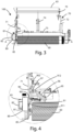
figure 3 shows a side view of the working unit offigure 2 in a head fixing configuration; -
figure 4 shows a detail offigure 3 ; -
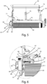
figure 5 shows a side view of the working unit offigure 2 in a head disengagement configuration; -
figure 6 shows a detail offigure 5 ; -
figure 7 shows a side view of the working unit infigure 2 during the replacement of the interchangeable sleeve; -
figure 8 shows a detail offigure 7 ; -
figure 9 shows a perspective view of the head connection in a preferred embodiment; -
figure 10 shows a perspective view of the upright and the roller in the embodiment offigure 9 ; -
figure 11 shows a detail of the head in the embodiment offigure 9 ; -
figure 12 shows a sleeve translation blocking device in a preferred embodiment. - In the various figures, similar parts will be indicated with the same numerical references.
- The description below will be aimed at the working of wooden panels P, but it is clear that it should not be considered limited to this specific use, as the machine here proposed can also be used for the working of metal or other material panels.
- In the following, similar parts of the described embodiments will be indicated with the same numerical references.
-
Figure 1 illustrates a sanding machine M in a preferred embodiment of the present invention. - The sanding machine M comprises an
inlet station 1, where the panels P to be worked are inserted according to an advancement direction F, parallel to the X-axis of the Cartesian reference system XYZ, anoutlet station 2 from which worked panels P come out, according to the same direction F, a workingsurface 3 for supporting and transporting the panel to be worked according to an advancement direction F, from theinlet station 1 towards theoutlet station 2, and at least one workingunit 100 to carry out a working, in particular a sanding or calibration, on the panel P. - In particular, the machine M can allow to automatically create a finishing effect similar to that of a manual sanding.
- In particular, the working
surface 3 comprises a belt wrapped around pulleys, moving along the advancement direction F, parallel to the X-axis of the Cartesian reference system XYZ, on which the panel P is placed during an operational step of the working. - The
working unit 100 comprises anoperator roller 60 for sanding the panel P arranged on the workingsurface 3. - The
operator roller 60 is rotatable around a rotation axis A-A, an axis substantially transverse to the X-axis, in a discordant way with respect to the aforementioned advancement direction F, and is arranged above theworking surface 3, between theinlet 1 and theoutlet 2. - The
operator roller 60 comprises ametal core 61, for example substantially cylindrical or conical, and acoating 62, shaped like an interchangeable sleeve, for example substantially cylindrical or conical (figure 7 ) - The coating, shaped for example as an interchangeable
cylindrical sleeve 62, can be removed from the metal core and/or slipped onto the substantiallycylindrical metal core 61 of theoperator roller 60. - The
working unit 100 comprises atensioning roller 63, idle, positioned above theoperator roller 60, and an abrasive belt (not shown), wrapped or configured to be wrapped around theaforementioned tensioning roller 63 andoperator roller 60. Therefore, theoperator roller 60 operates as a reference for the abrasive belt during a sanding process on the panel P. - In an alternative embodiment, the working unit can be positioned below the working surface, for example to allow the working of a lower face of the panel.
- The working
unit 100 comprises a supportingframe 70, configured to support theoperator roller 60 and thetensioning roller 63, in particular above the workingsurface 3. - As shown in
figure 2 , the supportingframe 70 comprises afirst upright 71 and asecond upright 72. Theoperator roller 60 is arranged between thefirst upright 71 and thesecond upright 72. - The supporting
frame 70 comprises areference crosspiece 73 positioned between the firstupright element 71 and the secondupright element 72, in particular above the workingsurface 3. - Furthermore, the supporting
frame 70 comprises a transverse supportingelement 75, positioned above thereference crosspiece 73, configured to support free rotation of thetensioning roller 63. - To maintain the tension of the belt during machine operation and, at the same time, guarantee the possibility of loosening it when replacing the abrasive belt, the supporting frame comprises a
belt tensioning piston 74, positioned between thereference crosspiece 73 and the transverse supportingelement 75. - Advantageously, the
belt tensioning piston 74 is configured to allow a translation along the Z-axis of thetensioning roller 63 with respect to thereference crosspiece 73. - To ensure that a gripping contact between the
operator roller 60 and the abrasive belt is maintained, during the rotation of theoperator roller 60 thecoating 62 of themetal core 61 is preferably made of rubber or composite material. - In particular, the hardness of the rubber, or of the composite material, used to make the
interchangeable sleeve 62 defines the working pressure value of the abrasive belt on the panel P, thus impacting the quality of the working performed. - To facilitate the operations of replacing the
interchangeable sleeve 62 with respect to themetal core 61, it is advantageously provided a compressed air system that comprises a plurality of ducts in themetal core 61, from a central axis of themetal core 61 to an external surface of themetal core 61 itself, to allow the introduction of compressed air during the step of removing theinterchangeable sleeve 62. - According to the invention, the working
unit 100 comprises ahead 80 associated with at least one of theuprights first upright 71, and suitable for connecting theoperator roller 60 to the upright 71 with which it is associated. Thehead 80 is movable between a first fixing position of theoperator roller 60 to thefirst upright 71, and a second position of distancing from theoperator roller 60. - Preferably in the first position the
head 80 is arranged at a first height with respect to thefirst upright 71 and in the second position thehead 80 is arranged at a second height different from said first height. -
Figure 3 shows the workingunit 100 in a configuration in which thehead 80 is in the first fixing position. - In the illustrated embodiment, the
head 80 has a box-shapedportion 81. On the external part of the box-shapedportion 81, facing the operator, at least one grippingelement 82 is arranged. In the figures thegripping element 82 is made up of two handles. At least oneoperating button 83 is advantageously arranged on thegripping element 82. - The external face of the box-shaped
portion 81 has one ormore holes 84 for inserting and tightening corresponding screws to fix thehead 80 to theupright 71 and to theoperator roller 60. - Preferably, the
head 80 has on the internal face afirst plate 85 connected with theupright 71 and the operator roller 60 (figure 9 ). Preferably thefirst plate 85 extends lower than the box-shapedportion 81. - In particular, as illustrated in
figure 10 , thefirst upright 71 has one ormore holes 711 arranged in correspondence with alower end 712. Asecond plate 64 is associated with theoperator roller 60 arranged in correspondence with anend 65 of theoperator roller 60 which faces the header. Thesecond plate 64 is provided with one ormore holes 641. - On the internal face of the
head 80, in particular on the internal face of thefirst plate 85, at least one connectingrod - The connecting
rod first upright 71. - In this way, the
head 80 is connected to thefirst upright 71 even when the screws are not tightened. - In the embodiment illustrated in
figures 4 ,6 , and8 , thefirst end 901 of a first upper connectingrod 90 and thefirst end 911 of a second lower connectingrod 91 are hinged on the internal face of thehead 80. - The
second end 902 of the firstupper connecting rod 90 and thesecond end 912 of the second lower connectingrod 91 are hinged to components fixed on thefirst upright 71. - Advantageously, the
head 80 is movable between the first fixing position and an intermediate disengagement position with respect to theoperator roller 60. - In the embodiment illustrated in
figures 5 and 6 , in the intermediate position thehead 80 is preferably arranged at a lower height than the first fixing position. - In the intermediate position, the
head 80 remains connected to thefirst upright 71, but is no longer fixed to theoperator roller 60. - Advantageously, to carry out the movement of the
head 80 from the first position to the intermediate position, at least onedrive element 95 is provided, interposed between thehead 80 and the supportingframe 70. - Preferably, the
head 80 is moved from the first position to the intermediate position by at least one translation movement in a plane substantially perpendicular to the A-A axis of theroller 60. In particular, thehead 80 moves by translating along thefirst upright 71. - In the illustrated embodiment, to carry out the movement of the
head 80 from the first position to the intermediate position, thedrive element 95 preferably comprises alinear actuator 96 connected to at least one connectingrod 91. Advantageously, aneccentric shaft 97 is provided, interposed between thelinear actuator 96 and the connectingrod 91. - In particular, as illustrated in
figure 4 , in the fixing position thelinear actuator 96, for example a pneumatic cylinder, is in the working position so as to keep theeccentric shaft 97 in a blocking position of the corresponding lower connectingrod 91. - Following a command, for example by acting on at least one of the
buttons 83 of thehandles 82 arranged on thehead 80, the piston of thepneumatic cylinder 96 moves to the retracted position, rotating theeccentric shaft 97. The rotation of theeccentric shaft 97 rotates the lower connectingrod 91, which causes thehead 88 to descend. The variation in height of thehead 88 depends, among other things, on the sizing of theeccentric shaft 97. In a preferred embodiment, this variation is approximately 10 mm. - Advantageously, the internal face of the
head 80 comprises asupport 86 for the roller axis. In particular, as shown infigure 11 , thefirst plate 85 of thehead 80 has anopening 87 having a substantiallyhorizontal stop 88 in the lower portion. - In this way, when the
head 80 is released from theroller 60, it is possible to recover the deflection of theroller 60, which is cantilevered with respect to thesecond upright 72. -
Figures 7 and 8 illustrate the workingunit 100 in a configuration that allows the replacement of thesleeve 62 of theoperator roller 60. - In this configuration, the
head 80 is in a second position of distancing from theoperator roller 60. In particular, in the second position thehead 80 is arranged at a higher height than in the first position. - In an alternative embodiment, not illustrated, in the second position the head is arranged at a lower height than in the first position, but in such a way as to directly free the access to the roller.
- In a further embodiment, not illustrated, the head can remain substantially at the same height as the first position or the intermediate position and rotate around a vertical axis to free the access to the roller.
- Advantageously, the
head 80 is moved between the first position and the second position or between the intermediate position and the second position by means of at least one rotational movement around an axis substantially perpendicular to thefirst upright 71. - In particular, the
head 80 moves on a curved trajectory remaining substantially parallel to thefirst upright 71. - In the illustrated embodiment, to move the
head 80 from the intermediate position to the second position, a force is applied on thehandles 82 directed towards the outside of theframe 70, substantially in the direction of the A-A axis of theroller 60. - In an alternative embodiment, the
head 80 can be moved from the first fixing position to the second fixing position by applying a force on thehandles 82 directed towards the outside of theframe 70, substantially in the direction of the A-A axis of theroller 60. - The configuration of the connecting
rods head 80 in a vertical direction, first away from thefirst upright 71 and then towards the upright 71 itself. This movement is facilitated by using at least one gas spring interposed between theframe 70 and thesecond end 912 of the lower connectingrod 91. - In an alternative embodiment, not illustrated, the
head 80 can move between the first position and the second position or between the intermediate position and the second position by rotating around a vertical axis or around an axis perpendicular to both thefirst upright 71 and theroller axis 60. - The present invention also concerns a method of replacing an
interchangeable sleeve 62 of anoperator roller 60 in a workingunit 100 of a sanding machine. - The method involves the steps of:
- bringing the
head 80 from the first fixing position to an intermediate disengagement position with respect to theoperator roller 60, - bringing the
head 80 into a second position of distancing from theoperator roller 71; - moving the
sleeve 62 of theoperator roller 60 along the axis A-A of theroller 60 towards the outside of theframe 70; - replacing the
sleeve 62; - inserting a new sleeve along the A-A axis of the
roller 60 towards the inside of theframe 70; - bringing the
head 80 to the intermediate disengagement position; - bringing the
head 80 into the first fixing position; - fixing the
head 80 to thefirst upright 71 and to theoperator roller 60. - In particular, in the illustrated embodiment, to replace the
sleeve 62 of theoperator roller 60, the fixing screws arranged on thehead 80 are first loosened. Thehead 80 remains blocked in the fixing position by the lower connectingrod 91 which is held in position by the piston of thepneumatic cylinder 96. - By acting on the
button 83 of one of thehandles 82 thepneumatic cylinder 96 is activated and the piston is retracted. The movement of the piston rotates theeccentric shaft 97, which in turn causes the movement of the lower connectingrod 91. The movement of the lower connectingrod 91 lowers thehead 80, disengaging it from theroller 60. - The
roller 60 remains cantilevered and can rest on thehorizontal stop 88 of thefirst plate 85 associated with the internal face of thehead 80. - To allow access to the
roller 60 and remove thesleeve 61, thehead 80 is moved towards the outside of theframe 70, acting on thehandles 82. Through the connectingrods head 80 lifts up so that thelower edge 851 of theplate 85 reaches a height higher than thelower end 712 of thefirst upright 71 and allows the passage of the sleeve 62 (figures 7 and 8 ). - The compressed air is then activated so that the
sleeve 62 begins to slide on theroller 60 towards the operator. - According to another aspect of the present invention, the working
unit 100 has a device for blocking 110 the translation of thesleeve 62 along the A-A axis of theroller 60 towards the outside of theframe 70. - In fact, the compressed air could cause the sleeve to suddenly push towards the operators who are near the machine.
- The
blocking device 110 advantageously comprises at least onearm 111 assembled on oneend 65 of the roller. Awheel 112 is preferably hinged at one end of thearm 111. Thearm 111 is preferably assembled by means of aspring 113 which keeps thearm 111 in an opening configuration that blocks the translation of thesleeve 62 on thecore 61 of theroller 60, preventing it from slipping off. - In the embodiment illustrated in
figure 12 , theblocking device 110 comprises afirst arm 111 and asecond arm 114, mounted on thesecond plate 64 associated with theroller 60 by means of arespective spring 113. When it is intended to remove thesleeve 62 from theroller 60, thearm sleeve 62, which is spaced apart from thecore 61 of theroller 60 thanks to the compressed air, and thesleeve 62, which slides on thewheel 112 associated with therespective arm sleeve 62, thearms core 61 of theroller 60, and thesleeve 62, which slides on thewheel 112 up to the final position, is inserted. When thesleeve 62 is placed completely on thecore 61, thearms spring 113. - After carrying out the replacement, the compressed air is turned off.
- The
head 80 is lowered via thehandles 82 and brought to the intermediate position, which is at a lower height than the first fixing position. - The
horizontal stop 88 of theopening 87 of thefirst plate 85 of thehead 80 engages the reference pins 642 present on thesecond plate 64 associated with the roller (figures 9 and 10 ). Thehead 80 is then lifted to be returned to the fixing position. Theoperating button 83 is then pressed, which, through the rotation of theeccentric shaft 97, moves the lower connectingrod 91, lifting thehead 80 and returning it to the fixing position. Thehead 80 is then rigidly constrained to thefirst upright 71 and to theroller 60 via the fixing screws. - The present invention has been described for illustrative but not limitative purposes, according to its preferred embodiments, but it is to be understood that modifications and/or changes can be introduced by those skilled in the art without departing from the relevant scope as defined in the enclosed claims.
Claims (14)
- Working unit (100) of a panel (P), suitable to be inserted in a sanding machine,said working unit comprising an operator roller (60) rotatable around a rotation axis (A-A),a tensioning roller (63) rotatable around an axis substantially parallel to said axis (A-A),an abrasive belt stretched and circulating between said operator roller (60) and said tensioning roller (63), said abrasive belt being dragged and pressed against said panel (P) by said operator roller (60) during working, anda supporting frame (70) configured to support said operator roller (60) and said tensioning roller (63), said supporting frame (70) comprising at least a first (71) upright and a second upright (72), wherein said operator roller (60) is arranged between said first upright (71) and said second upright (72), said working unit being characterized in that it comprises a head (80) linked to at least said first upright and adapted to connect said operator roller (60) to said first upright (71), in which said head (80) is movable between a first position of fixing of said operator roller (60) to said first upright (71), and a second position of distancing from said operator roller (60).
- Working unit according to the preceding claim, wherein in said first position said head (80) is arranged at a first height and in said second position said head (80) is arranged at a second height different from said first height.
- Working unit according to claim 1 or 2, wherein said head (80) is movable between said first fixing position and an intermediate disengagement position in which said head is released from said operating roller (60).
- Working unit according to the preceding claim, wherein in said intermediate position said head (80) is arranged at a lower height than said first fixing position.
- Working unit according to any of the preceding claims, wherein said head (80) is moved by at least one translation movement in a plane substantially perpendicular to the axis (A-A) of said operator roller (60).
- Working unit according to any one of the preceding claims, wherein said head (80) is moved by at least one rotation movement around an axis substantially perpendicular to said first upright (71).
- Working unit according to any one of the preceding claims 3-6, comprising at least one drive element (95) interposed between said head (80) and said supporting frame (70) to move said head (80) from said first fixing position to said intermediate disengagement position.
- Working unit according to the preceding claim, wherein said drive element (95) comprises at least one linear actuator (96) connected to at least one connecting rod (91).
- Working unit according to the preceding claim, comprising at least one eccentric shaft (97) interposed between said linear actuator (96) and said connecting rod (91).
- Working unit according to any one of the preceding claims, comprising at least a pair of connecting rods (90, 91) each having a first end (901, 911) hinged to said head (80) and a second end (902, 912) hinged to said supporting frame (70).
- Working unit according to any one of the preceding claims, wherein said operator roller (60) comprises an inner core (61) and a coating (62) configured as an interchangeable sleeve, said working unit (100) comprising a device for blocking (110) the translation of said sleeve (62) along the axis (A-A) of said operator roller (60).
- Working unit according to the preceding claim, wherein said blocking device (110) includes at least one arm (111, 114) mounted on one end of said operator roller (60), at least one wheel (112) hinged to the end of the arm (111, 114) and at least one spring (113) placed between said arm (111, 114) and said operator roller (60).
- Sanding machine (M) for sanding at least one panel (P), comprising:- an inlet station (1) for the entry of a panel (P) to be worked and an outlet station (2) for the exit of the worked panel (P);- a working surface (3) for transporting the panel (P) to be worked, according to an advancement direction (F), from said inlet station (1) to said outlet station (2);- at least one working unit (100) according to any one of the preceding claims, wherein said working unit is arranged facing said working surface (3), to work one face of said panel (P), said working unit ( 100) being able to sand the panel (P) during the passage of the panel from said inlet station (1) to said outlet station (2).
- Method of replacing an interchangeable sleeve (62) of an operator roller (60) in a working unit according to any one of claims 1 to 12, wherein the method comprises the steps of: moving said head (80) from the first fixing position to an intermediate position of disengagement from the operator roller (60),bringing the head (80) into the second position of distancing from said operator roller (60);moving the sleeve (62) of the operator roller (60) along the axis (A-A) of the roller (60) towards the outside of the frame (70);replacing the sleeve (62);inserting a new sleeve along the axis (A-A) of the operator roller (60) towards the inside of the frame (70);bringing the head (80) to the intermediate disengagement position;bringing the head (80) to the first fixing position;fixing the head (80) to the first upright (71) and to the operator roller (60).
Applications Claiming Priority (1)
| Application Number | Priority Date | Filing Date | Title |
|---|---|---|---|
| IT102023000019761A IT202300019761A1 (en) | 2023-09-26 | 2023-09-26 | WORKING UNIT FOR SANDER MACHINE WITH VARIABLE HARDNESS ROLLER. |
Publications (1)
| Publication Number | Publication Date |
|---|---|
| EP4530017A1 true EP4530017A1 (en) | 2025-04-02 |
Family
ID=89158299
Family Applications (1)
| Application Number | Title | Priority Date | Filing Date |
|---|---|---|---|
| EP24201479.3A Pending EP4530017A1 (en) | 2023-09-26 | 2024-09-19 | Machining unit for a sanding machine with a variable hardness roller |
Country Status (2)
| Country | Link |
|---|---|
| EP (1) | EP4530017A1 (en) |
| IT (1) | IT202300019761A1 (en) |
Citations (1)
| Publication number | Priority date | Publication date | Assignee | Title |
|---|---|---|---|---|
| EP4129570A2 (en) * | 2021-08-06 | 2023-02-08 | SCM Group S.p.A. | Sanding machine provided with a variabile hardness roller |
-
2023
- 2023-09-26 IT IT102023000019761A patent/IT202300019761A1/en unknown
-
2024
- 2024-09-19 EP EP24201479.3A patent/EP4530017A1/en active Pending
Patent Citations (1)
| Publication number | Priority date | Publication date | Assignee | Title |
|---|---|---|---|---|
| EP4129570A2 (en) * | 2021-08-06 | 2023-02-08 | SCM Group S.p.A. | Sanding machine provided with a variabile hardness roller |
Also Published As
| Publication number | Publication date |
|---|---|
| IT202300019761A1 (en) | 2025-03-26 |
Similar Documents
| Publication | Publication Date | Title |
|---|---|---|
| CN111390713B (en) | Electric insulator machining and forming process | |
| CN110394644B (en) | Automatic fan impeller assembling production line | |
| EP0004202B1 (en) | Modular tire building machine | |
| KR101591448B1 (en) | Automatic riveting device | |
| EP4129570B1 (en) | Sanding machine provided with a variabile hardness roller | |
| CN110315336B (en) | A equipment swager constructs for on fan wheel automatic assembly production line | |
| KR930007106B1 (en) | Cylindrical grinding machine suitable for use on the rolls of rolling mill of the like | |
| EP0191189B1 (en) | Spinning type multiple roller forming machine | |
| EP2241401B1 (en) | Belt sanding machine | |
| JP2546857B2 (en) | Work transfer device | |
| CN217254879U (en) | Machine tool waste cleaning device | |
| CN210281785U (en) | Abrasive belt replacing mechanism | |
| IT202300019761A1 (en) | WORKING UNIT FOR SANDER MACHINE WITH VARIABLE HARDNESS ROLLER. | |
| US3745611A (en) | Apparatus for shirring artificial sausage casing | |
| CN210121803U (en) | Polishing machine for graphite workpiece | |
| CN110802919B (en) | Large-scale automatic silk screen printing equipment | |
| SU1326183A3 (en) | Device for cleaning round electrodes | |
| JP2860139B2 (en) | Hose processing equipment | |
| SU1757896A1 (en) | Press for making hollow rubber goods | |
| CN222249262U (en) | Ship loader with adjustable conveying stroke | |
| CN217417669U (en) | Conveying device for automatic cutting machine for spectacle case production | |
| CN220222823U (en) | Abrasive cloth winding device | |
| SU1731598A1 (en) | Article fastening device | |
| CN222138190U (en) | Automatic width-adjusting conveying belt winding device | |
| CN220029720U (en) | Swing slag remover |
Legal Events
| Date | Code | Title | Description |
|---|---|---|---|
| PUAI | Public reference made under article 153(3) epc to a published international application that has entered the european phase |
Free format text: ORIGINAL CODE: 0009012 |
|
| STAA | Information on the status of an ep patent application or granted ep patent |
Free format text: STATUS: THE APPLICATION HAS BEEN PUBLISHED |
|
| AK | Designated contracting states |
Kind code of ref document: A1 Designated state(s): AL AT BE BG CH CY CZ DE DK EE ES FI FR GB GR HR HU IE IS IT LI LT LU LV MC ME MK MT NL NO PL PT RO RS SE SI SK SM TR |
|
| STAA | Information on the status of an ep patent application or granted ep patent |
Free format text: STATUS: REQUEST FOR EXAMINATION WAS MADE |
|
| 17P | Request for examination filed |
Effective date: 20250929 |