EP4529968A2 - Becken mit einem wasserzirkulationssystem - Google Patents
Becken mit einem wasserzirkulationssystem Download PDFInfo
- Publication number
- EP4529968A2 EP4529968A2 EP25157916.5A EP25157916A EP4529968A2 EP 4529968 A2 EP4529968 A2 EP 4529968A2 EP 25157916 A EP25157916 A EP 25157916A EP 4529968 A2 EP4529968 A2 EP 4529968A2
- Authority
- EP
- European Patent Office
- Prior art keywords
- water outlet
- pool
- water
- shell
- assembly
- Prior art date
- Legal status (The legal status is an assumption and is not a legal conclusion. Google has not performed a legal analysis and makes no representation as to the accuracy of the status listed.)
- Pending
Links
Images


Classifications
-
- E—FIXED CONSTRUCTIONS
- E04—BUILDING
- E04H—BUILDINGS OR LIKE STRUCTURES FOR PARTICULAR PURPOSES; SWIMMING OR SPLASH BATHS OR POOLS; MASTS; FENCING; TENTS OR CANOPIES, IN GENERAL
- E04H4/00—Swimming or splash baths or pools
- E04H4/12—Devices or arrangements for circulating water, i.e. devices for removal of polluted water, cleaning baths or for water treatment
-
- B—PERFORMING OPERATIONS; TRANSPORTING
- B01—PHYSICAL OR CHEMICAL PROCESSES OR APPARATUS IN GENERAL
- B01D—SEPARATION
- B01D35/00—Filtering devices having features not specifically covered by groups B01D24/00 - B01D33/00, or for applications not specifically covered by groups B01D24/00 - B01D33/00; Auxiliary devices for filtration; Filter housing constructions
- B01D35/30—Filter housing constructions
- B01D35/306—Filter mounting adapter
-
- B—PERFORMING OPERATIONS; TRANSPORTING
- B01—PHYSICAL OR CHEMICAL PROCESSES OR APPARATUS IN GENERAL
- B01D—SEPARATION
- B01D35/00—Filtering devices having features not specifically covered by groups B01D24/00 - B01D33/00, or for applications not specifically covered by groups B01D24/00 - B01D33/00; Auxiliary devices for filtration; Filter housing constructions
- B01D35/02—Filters adapted for location in special places, e.g. pipe-lines, pumps, stop-cocks
- B01D35/027—Filters adapted for location in special places, e.g. pipe-lines, pumps, stop-cocks rigidly mounted in or on tanks or reservoirs
-
- E—FIXED CONSTRUCTIONS
- E04—BUILDING
- E04H—BUILDINGS OR LIKE STRUCTURES FOR PARTICULAR PURPOSES; SWIMMING OR SPLASH BATHS OR POOLS; MASTS; FENCING; TENTS OR CANOPIES, IN GENERAL
- E04H4/00—Swimming or splash baths or pools
- E04H4/0018—Easily movable or transportable swimming pools
- E04H4/0025—Easily movable or transportable swimming pools with inflatable parts
-
- E—FIXED CONSTRUCTIONS
- E04—BUILDING
- E04H—BUILDINGS OR LIKE STRUCTURES FOR PARTICULAR PURPOSES; SWIMMING OR SPLASH BATHS OR POOLS; MASTS; FENCING; TENTS OR CANOPIES, IN GENERAL
- E04H4/00—Swimming or splash baths or pools
- E04H4/06—Safety devices; Coverings for baths
-
- E—FIXED CONSTRUCTIONS
- E04—BUILDING
- E04H—BUILDINGS OR LIKE STRUCTURES FOR PARTICULAR PURPOSES; SWIMMING OR SPLASH BATHS OR POOLS; MASTS; FENCING; TENTS OR CANOPIES, IN GENERAL
- E04H4/00—Swimming or splash baths or pools
- E04H4/12—Devices or arrangements for circulating water, i.e. devices for removal of polluted water, cleaning baths or for water treatment
- E04H4/1209—Treatment of water for swimming pools
- E04H4/1245—Recirculating pumps for swimming pool water
Definitions
- the present disclosure relates to the technical field of circulating filtration for pools. More specifically, the present disclosure relates to a pool having a water circulation system. The present disclosure further relates to a pool comprising a water circulation system configured to reduce risk of injury from a user's body part being drawn into a water outlet from which an external pump draws water out of the pool.
- a pool 1 is provided with a water inlet 3 in fluid communication with an external pump 2 and a water outlet 4 with a filter 5. If the filter 5 is removed, but not replaced with a new filter, suction at the water outlet may draw the user's body or hair against or into the water outlet. In some cases, this suction may be powerful enough that the user may be unable to free themself from the water outlet, which can result in injury to the user.
- the available area is limited, and therefore, the positions of the water outlets can affect a user's experience, so large spacing between two water outlets can result in a waste of usable space. Furthermore, large spacing between multiple water outlets can reduce production efficiency.
- the water outlet assembly comprises a water outlet device having a sidewall and an end; the at least one through hole is provided on the sidewall of the water outlet device and the plurality of water outlet orifices are provided on the end of the water outlet device.
- a water circulation system for a pool generally comprises a water inlet assembly 30 and a water outlet assembly 40.
- the water inlet assembly 30 is mounted to an inner wall 11 of the pool 10, with a water inlet device 32 in fluid communication with an external pump 20 through a water inlet pipe 31.
- a water outlet assembly 40 is mounted to the inner wall 11, with a water outlet device 42 in fluid communication with the external pump 20 through a water outlet pipe 41.
- a filter 80 may be mounted to the water outlet device 42.
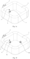
- a water circulation system with an air inlet assembly 60 and an air outlet assembly 50 is provided, wherein the air inlet assembly 60 is connected to the air outlet assembly 50 through an air inlet passage 63.
- the air inlet assembly 60 is mounted to the pool a preset distance from a water outlet assembly 40, and the air outlet assembly 50 is attached to the water outlet assembly 40 on the inner wall 11 of the pool and in fluid communication with the water outlet assembly 40.
- the water circulation system can introduce external air from the air inlet assembly 60 to the air outlet assembly 50 through the air inlet passage 63 and then to the water outlet assembly 40 via the air outlet assembly 50.
- the air outlet assembly 50, 90 of the water circulation system may be configured to be in fluid communication with the water outlet assembly 40 when the water outlet assembly 40 is not connected to a filter 80, but not in fluid communication with the water outlet assembly 40 when the water outlet assembly 40 is connected to the filter 80.
- the filter 80 when the filter 80 is not installed at the water outlet assembly 40, water and/or air can flow into the water outlet pipe 41 from the air outlet assembly 50, 90, as well as from the water outlet assembly 40. Even if the water outlet of the water outlet assembly 40 is blocked, water flow or air flow can still flow from the air outlet assembly 50, 90 to the water outlet pipe 41, thereby effectively protecting the user.
- the filter 80 is installed on the water outlet assembly 40, water flow can only flow into the water outlet pipe 41 via the filter 80, thereby providing the filtering effect.
- the installation port 912 of the shell 91 may also receive the water inlet assembly 30.
- the shell 91 serves as both an air inlet assembly and an air outlet assembly, and the internal cavity of the shell 91 also defines the air inlet passage.
- Other embodiments of the present disclosure include the air inlet assembly mounted to the inner wall, the top wall or the outer wall of the pool.
- the pool 10 is an inflatable pool, and the air inlet passage 63 is disposed in an air chamber of the inflatable pool.
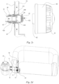
- the water outlet device 42 is at least partially located inside the shell 91, and the water outlet device 42 includes a plurality of water outlet orifices 421 and a plurality of through holes 422 in a side wall thereof.
- a circumferential side wall of the water outlet device 42 includes external threads that cooperate with internal threads of the filter 80, so that a user can conveniently install the filter 80 onto the water outlet device 42.
- the plurality of through holes 422 may be on or adjacent to the external threads of the water outlet device 42, but the through holes 422 do not affect the connection function of the external threads.
- the water outlet device may be provided with a water outlet device joint 42b connected to the inner wall of the pool.
- the water outlet device joint 42b may be integrally formed or separately connected with the water outlet device 42.
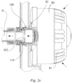
- the through holes 422 may be circumferentially arranged in the side wall of the water outlet device 42 and adjacent to the water outlet device joint 42b, as shown in Fig. 2c , thereby providing fluid communication between the internal cavity of the shell 91 and the water outlet assembly 40 via the through holes 422.
- the fluid passage in the shell 91 is not in communication with the water outlet device 42, and water flow cannot enter the water outlet pipe 41 via the through holes 422, but can only flow in through the filter ports 81 of the filter 80, as indicated by the depicted arrows, and then return to the pool via the water outlet pipe 41, the pump 20, the water inlet pipe 31 and the water inlet device 32.
- the filter 80 is removed, it should be understood that the base 100 is reset under the action of the elastic member 110 to abut against the inner wall of the shell 91, and the through holes 422 are in fluid communication with the shell 91 again. In this way, after the filter 80 is installed, water flow can only flow into the water outlet pipe via the filter, thereby providing the filtering effect.
- the water outlet assembly 40 may comprise a water outlet pipe connector connecting the water outlet pipe 41 in fluid communication with the water outlet device 42.
- the water outlet pipe connector comprises a water outlet pipe joint 43 connected to the water outlet pipe 41, and a water outlet device joint 42b connected to the water outlet pipe joint 43 for connection to the water outlet device 42.
- one end of the water outlet pipe joint 43 may be, for example, connected to the water outlet pipe 41 by a nut 44, and the other end may be, for example, fixed to the inner wall 11 of the pool by a flexible connector 45 fixed to the inner wall 11 of the pool.
- the water outlet pipe joint 43 may be connected to the flexible connector 45 by means of secondary injection molding.
- the water outlet device joint 42b is hermetically connected to the inner wall 11 of the pool.
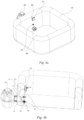
- Figs. 3a and 3b show a water circulation system according to a second embodiment of the present disclosure.
- This second embodiment is different from the embodiment described above and shown in Figs. 2a - 2e in that the water outlet device 42 of Figs. 3a - 3b does not include an elastic member or a base. Instead, the water flow blocking member is the connection interface 82 of the filter 80, and when the filter 80 is installed to the water outlet device 42, the through holes 422 are directly blocked by the connection interface 82, as shown in Fig. 3b .
- water flow cannot enter the water outlet pipe from the shell 91, or only an extremely small amount of water flow can enter the water outlet pipe from the shell 91.
- water flows in from the filter ports 81 of the filter 80 as indicated by the depicted arrows, and then returns to the pool via the water outlet pipe 41, the pump 20, the water inlet pipe 31 and the water inlet device 32.
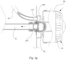
- Figs. 4a to 4g show a water circulation system according to a third embodiment of the present disclosure.
- the air inlet assembly 60 comprises an air inlet outer cover 61 installed on the inner wall 11 of the pool.
- the air inlet outer cover 61 is provided with a plurality of air inlets 611, for example, as the air inlets of the outer cover grille.
- the air inlet passage 63 is arranged between the inner wall 11 and the outer wall 12 of the pool and is connected to the air inlet outer cover 61 and the air outlet assembly 50 by means of joints, respectively.
- the air inlet passage can be arranged within the inflatable chamber like the water inlet pipe and the water outlet pipe, so as to avoid failure due to damage that may otherwise be sustained when placed outside of the wall of the pool.
- the air inlet passage 63 may comprise, for example, a flexible hose, and may be thus easily sheathed on the joint to achieve fluid communication between the air inlet outer cover 61 and the air outlet assembly 50.
- the air outlet assembly 50 comprises a shell 501 fixed to the inner wall 11 of the pool. As shown in Fig. 4c , the shell 501 is provided with a first installation port 51 for installation of the air inlet passage 63 and a second installation port 52 for installation of the water outlet assembly, wherein the shell 501 has an internal cavity to connect the air inlet passage with the water outlet assembly.
- the air inlet assembly 60 may be mounted a preset distance from the water outlet assembly 40.
- the air inlet outer cover 61 is located at an upper part of the inner wall 11 of the pool.
- at least some of the air inlets 611 are above the in-use water level of the pool. In this way, since at least some of the air inlets 611 of the air inlet outer cover 61 are exposed to the outside atmosphere when in normal use, even if the air inlets below the water surface are blocked, the flow of gas, such as air, can still be introduced through the air inlets 611 above the water surface, thus ensuring that fluid flow can continue to enter the air outlet assembly 50 from the air inlet passage 63 and then enter the water outlet pipe 41 from the air outlet assembly 50. Since air enters the water outlet pipe 41 more easily, the negative pressure at the water outlet of the water outlet assembly 40 is greatly reduced, thereby reducing the risk of drawing the user's body or hair against or into the water outlet assembly 40.
- the air inlet passage 63 may be connected to the air inlet outer cover 61 and the shell 501 by means of a joint provided on the air inlet outer cover 61 and the shell 501, where each joint may be integrally molded or cooperatively connected with the air inlet outer cover 61 or the shell 501.
- a first joint 62 may be integrally formed on the air inlet outer cover 61
- a second joint 64 may be connected to the shell 501.
- at least one of the joints 62, 64 may be fixed with a rubber coating to the inner wall of the pool, the top wall of the pool, or the outer wall of the pool.
- at least one of the joints 62, 64 may be integrally formed with the air inlet outer cover 61 and/or the shell 501 of the air outlet assembly 50.
- an elastic member 110 is sheathed on the side wall of the water outlet device 42, and the base 100 serves as a water flow blocking member.
- part of the fluid flow (including air and/or water) enters the shell 501 from the air inlets 611 of the air inlet outer cover 61 via the air inlet passage 63, as indicated by the depicted arrows, and then enters the water outlet pipe 41 from the shell 501 via the through holes 422 of the water outlet device 42.
- another part of the fluid flow enters the water outlet pipe 41 through the water outlet orifices 421 of the water outlet device 42.
- connection interface 82 of the filter 80 abuts against the base 100, urging the base 100 to move towards the water outlet pipe 41 and squeezing the elastic member 110, causing the base 100 to block the through holes 422 in the side wall of the water outlet device 42.
- Figs. 5a to 5d show a water circulation system according to a fourth embodiment.
- the water circulation system of Figs. 5a to 5d is different from the water circulation system shown in Figs. 4b to 4d in that the water outlet device 42 is not provided with an elastic member or a base.
- the shell 501 of the water outlet assembly includes an annular wall 502 extending axially towards the internal cavity, and an opening 503 formed in the annular wall 502.
- part of the fluid flow (including air and/or water) enters the shell 501 from the air inlets 611 of the air inlet outer cover 61 via the air inlet passage 63, as indicated by the depicted arrows, and then enters the water outlet pipe 41 from the opening 503 of the shell 501 via the through holes 422 of the water outlet device 42.
- another part of the fluid flow enters the water outlet pipe 41 through the water outlet orifices 421 of the water outlet device 42.
- connection interface 82 of the filter 80 serves as a water flow blocking member to block the through holes 422, and thus as shown in Figs. 5c and 5d , water flow can only flow into the water outlet pipe 41 from the filter ports 81 of the filter 80, as indicated by the depicted arrows.
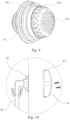
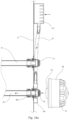
- Figs. 6 and 7 show a water circulation system for a pool according to a fifth embodiment.
- the air inlet assembly 60 of the fifth embodiment comprises an air inlet outer cover 61 installed to the inner wall 11 of the pool.
- the air inlet outer cover 61 is provided with a plurality of air inlets 611 in the form of a grille, as shown in Fig. 8 .
- the air outlet assembly 50 comprises a shell 501 fixed to the inner wall 11 of the pool, and the shell 501 is provided with a first installation port 51 for installation of the air inlet passage 63 and a second installation port 52 for installation of the water outlet assembly 40.
- a recessed portion that sinks into the internal cavity of the shell 501 may be formed at the second installation port 52 to receive at least part of the water outlet assembly.
- the first installation port 51 and the second installation port 52 may be provided with first air holes and second air holes in fluid communication with the internal cavity.
- second air holes 521 may be formed in the annular side wall of the recessed portion at the second installation port 52, as shown in Fig. 8 .
- the water outlet device 42 is received in the recessed portion at the second installation port 52 and is thus at least partially located inside of the shell 501.
- an annular gap may be formed between the outer circumference of the water outlet device and the shell 501, more specifically, between the outer circumference of the water outlet device and the inner circumference of the recessed portion, as shown in Fig. 13b .
- the water outlet device 42 comprises a plurality of water outlet orifices 421, such as a plurality of water outlet orifices 421a provided on an end surface and a plurality of water outlet orifices 421b provided on a side surface to achieve a certain filtering effect.
- the plurality of water outlet orifices 421 may have substantially the same size and/or shape. Alternatively, the plurality of water outlet orifices 421 may have different shapes and/or sizes.
- a plurality of through holes 422 are circumferentially arranged adjacent to the inner wall of the pool on the circumferential side wall of the water outlet device 42.
- second air holes 521 adjacent to the second installation port 52, are circumferentially arranged adjacent to the inner wall of the pool such that fluid communication exists between the air outlet assembly and the water outlet assembly through the second air holes 521 and the through holes 422.
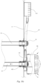
- the first installation port 51 and the second installation port 52 of the shell 501 are configured such that when the water outlet assembly is blocked, and more specifically, when the gap between the outer circumference of the water outlet device 42 and the inner circumference of the recessed portion of the shell 501 is blocked, as shown in Fig. 14b , the shell 501 and the water outlet device 42 form a substantially closed space.
- the water outlet device 42 is blocked but this gap is not blocked, as shown in Fig. 13b , the water outlet assembly is still in fluid communication with the pool.
- this gap is blocked, for example, if the water outlet is blocked by a portion of a user's body, a substantially closed space is formed between the shell 501 and the water outlet device 42.
- closed here does not means being completely closed. In a closed case, a large amount of fluid is blocked, and therefore, cannot enter from the water outlet device; however, a small amount of fluid may still flow into the shell 501. At this time, water flow cannot smoothly enter the water outlet pipe 41 from the water outlet device 42. Due to the operation of the pump, the internal pressure of the outlet pipe is reduced; external air enters the air outlet assembly from the air inlet assembly through the air inlet passage and is then introduced into the water outlet pipe through the through holes of the water outlet device; and fluid continues to circulate to partially reduce the negative pressure at the water outlet device, so that a user's body may escape from the water outlet device more easily to avoid injury.
- the through holes 422 are blocked by the connection interface 82 of the filter, so that water flow can only be circulated through the filter 80 and the water outlet device 42.
- the filter ports of the filter 80 for example, in the form of a grille, are kept at a certain distance from the water outlet device, which can ensure that the water outlet device will not be blocked.
- the water outlet device 42 may be connected to the water outlet pipe 41 via an integrally molded or separately connected water outlet device joint.
- the water outlet device may comprise a water outlet device portion 42a and a water outlet device joint 42b, and the water outlet device joint 42b may pass through the second installation port 52.
- the plurality of through holes 422 are provided in the circumferential side wall of the water outlet device joint 42b.
- the water outlet device joint 42b can pass through the second installation port 52 of the shell 501, and the water outlet device joint 42b is fixed to the pipe joint 43 of the water outlet pipe 41 with a threaded connection.
- the second air holes 521 of the second installation port 52 of the shell 501 may be in fluid communication with the through holes 422 of the water outlet device.
- connection between the water outlet device 42 and the water outlet pipe 41 takes the convenience of disassembly into consideration, while the connection between the air inlet outer cover 61 and the air inlet passage 63 and the connection between the air inlet passage 63 and the shell 501 of the air outlet assembly may include connections configured for ease of assembly and disassembly.
- the air inlet outer cover 61 may be fixedly connected to the first joint 62 connected to the air inlet passage 63 by screws, and the first joint 62 may be mounted to the inner wall of the pool by a rubber coating.
- the first joint 62 may be welded to the inner wall of the pool at high frequency by rubber coating of polyvinyl fluoride (PVC).
- PVC polyvinyl fluoride
- the first joint 62 includes a notch in fluid communication with the air inlet outer cover 61 to facilitate air circulation, as shown in Fig. 10 .
- the second joint 64 connected to the air inlet passage 63 may also be mounted to the inner wall of the pool by a rubber coating, and fixedly connected to the first installation port 51 of the shell 501 by screws.
- the second joint 64 includes a notch in fluid communication with the internal cavity of the shell 501.
- the notches and the connection interface shown in the figures are merely examples, and a variety of other configurations may be used to perform the same function.
- the shell 501a, 501b of the air outlet assembly 50 may comprise a first shell 501a and a second shell 501b connected to each other so that the first installation port 51 and the second installation port 52 are formed on the first shell 501a and/or the second shell 501b, and the first installation port 51 and the second installation port 52 each include air holes in fluid communication with the internal cavity.
- the first installation port 51 may be formed on the second shell 501b, and/or the second installation port 52 may be formed on the first shell 501a.
- a structural feature matching the first installation port 51 may be formed on the first shell 501a, so that the shell 501a, 501b can be fixedly connected to the second joint 64, for example, by screws. Such a connection may also attach the shell 501a, 501b with the inner wall of the pool.
- the annular wall of the second shell 501b extends axially toward the internal cavity and is perforated to form the first air holes 511 at a position adjacent to the first installation port 51.
- Fig. 11 the annular wall of the second shell 501b extends axially toward the internal cavity and is perforated to form the first air holes 511 at a position adjacent to the first installation port 51.
- the first shell 501a extends axially toward the internal cavity to form the recessed portion, and the annular wall of the recessed portion is perforated to form the second air holes 521 at a position adjacent to the second installation port 52.
- the first air holes 511 and the second air holes 521 allow air to circulate out of the internal cavity.
- the structure of the shell 501a, 501b in this embodiment is merely exemplary.
- the air outlet assembly and the water outlet assembly may be interconnected, as shown in Fig. 12 .
- water flow in the pool 10 enters the water outlet pipe 41 from the water outlet device 42, and then returns to the pool through the pump 20, the water inlet pipe 31, and the water inlet device 32.
- a gap is formed between the outer circumference of the water outlet device 42 and the inner circumference of the recessed portion of the shell 501.
- This gap provides for fluid communication between the through holes 422 in the circumferential side wall of the water outlet device and the pool, and water flow can continue to flow from the through holes 422 to the water outlet pipe 41 and return to the pool through the pump 20, the water inlet pipe 31, and the water inlet device 32.
- Such a partial blockage may be caused, for example, by hair, objects, clothes, or other obstructions 70.
- the through holes 422 of the water outlet device can still be used as water outlet orifices. If the gap between the outer circumference of the water outlet device and the inner circumference of the recessed portion is very small, the fluid inside of the air outlet assembly may partially flow into the through holes 422 of the water outlet device through the second air holes 521.
- the gap between the outer circumference of the water outlet device and the inner circumference of the recessed portion is also blocked, as shown in Figs. 14a and 14b .
- water cannot flow in smoothly from the water outlet device 42; the water outlet device 42 and the shell 501 form a relatively closed space; and the through holes 422 of the water outlet device are in fluid communication with the second air holes 521 of the shell 501.
- the pump continues to operate, drawing air from the air inlet outer cover 61.
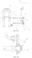
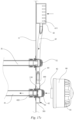
- Figs. 15a and 15b show a water circulation system for a pool according to a sixth embodiment.
- This sixth embodiment is different from the fifth embodiment of Figs. 6-7 in that the air inlet outer cover 61 of the air inlet assembly 60 is mounted to the outer wall 12 of the pool.
- the air inlets of the air inlet outer cover 61 are kept unblocked, and also the inner wall of the pool is simplified, thereby increasing the usable area of the pool and improving the user experience.
- the air inlet outer cover 61 is located at the upper part of the outer wall 12. Since the air inlets are continuously unblocked, in an alternative embodiment, the position of the air inlet outer cover 61 on the outer wall 12 is not limited, for example, it could be located at the middle, lower, or other parts of the outer wall 12.
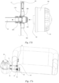
- Figs. 16a and 16b show a water circulation system for a pool according to a seventh embodiment.
- This seventh embodiment is different from the fifth embodiment of Figs. 6-7 in that the air inlet outer cover 61 of the air inlet assembly 60 is mounted to a top wall 13 of the pool. Such an arrangement also helps to keep the air inlets of the air inlet outer cover 61 continuously unblocked, thus improving the user experience.
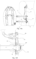
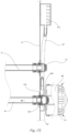
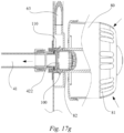
- Figs. 17a to 17g show a water circulation system according to an eighth embodiment.
- This eighth embodiment is different from the fifth embodiment of Figs. 6-7 in that the air inlet passage 63 is arranged in a pool body of the pool 10 and adjacent to the inner wall 11 of the pool.
- the term, "pool body,” means an interior space of the pool for containing water.
- the air inlet passage 63 may be in the form of a flexible hose that is easy to bend and will not produce adverse effects on the user.
- the air inlet passage of this embodiment is easier to maintain and replace.
- part of the fluid flow (including air and/or water) enters the shell 501 from the air inlets 611 of the air inlet outer cover 61 along the air inlet passage 63, as indicated by the depicted arrows, and then enters the water outlet pipe 41 from the shell 501 via the through holes 422 of the water outlet device 42.
- the other part of the fluid flow enters the water outlet pipe 41 through the water outlet orifices 421 of the water outlet device 42.
- connection interface 82 of the filter 80 abuts against the base 100, urging the base 100 to move towards the water outlet pipe 41 and then squeezing the elastic member 110, causing the base 100 to block the through holes 422 in the side wall of the water outlet device 42.
- Figs. 18a to 18d show a water circulation system according to a ninth embodiment.
- This ninth embodiment is different from the eighth embodiment of Figs. 17a to 17g in that the water outlet device 42 does not include an elastic member or a base.
- the shell of the water outlet assembly includes an annular wall 502 extending axially toward the inside of the internal cavity, and an opening 503 formed on the annular wall 502.
- the connection interface 82 of the filter 80 serves as a water flow blocking member to block the through holes 422, and thus, as shown in Figs. 18c and 18d , water flow can only flow into the water outlet pipe 41 from the filter ports 81 of the filter 80, as indicated by the depicted arrows.
- the water circulation system for a pool can reliably circulate and filter water in the pool and ensure the personal safety of users.
- the term "flexible” means providing for some relative motion between components.
- the components and features described herein may be made of various materials that include, but are not limited to, any suitable materials, such as polymers, rubber, foam and metal, or combinations of materials, which may be known to those skilled in the art.
Landscapes
- Engineering & Computer Science (AREA)
- Architecture (AREA)
- Civil Engineering (AREA)
- Structural Engineering (AREA)
- Water Supply & Treatment (AREA)
- Chemical & Material Sciences (AREA)
- Chemical Kinetics & Catalysis (AREA)
- Farming Of Fish And Shellfish (AREA)
- Devices For Medical Bathing And Washing (AREA)
- Filtration Of Liquid (AREA)
- Bathtub Accessories (AREA)
- Structure Of Emergency Protection For Nuclear Reactors (AREA)
Applications Claiming Priority (6)
| Application Number | Priority Date | Filing Date | Title |
|---|---|---|---|
| CN201910653252 | 2019-07-19 | ||
| CN201921138048 | 2019-07-19 | ||
| CN201911187017.1A CN112240110A (zh) | 2019-07-19 | 2019-11-28 | 用于水池的水循环系统及水池 |
| CN201922088453.5U CN211622779U (zh) | 2019-07-19 | 2019-11-28 | 用于水池的水循环系统及水池 |
| EP20844278.0A EP3999697B1 (de) | 2019-07-19 | 2020-07-16 | Wasserzirkulationssystem für ein becken und ein becken |
| PCT/CN2020/102453 WO2021013045A1 (en) | 2019-07-19 | 2020-07-16 | Water circulation system for a pool and a pool |
Related Parent Applications (2)
| Application Number | Title | Priority Date | Filing Date |
|---|---|---|---|
| EP20844278.0A Division EP3999697B1 (de) | 2019-07-19 | 2020-07-16 | Wasserzirkulationssystem für ein becken und ein becken |
| EP20844278.0A Division-Into EP3999697B1 (de) | 2019-07-19 | 2020-07-16 | Wasserzirkulationssystem für ein becken und ein becken |
Publications (2)
| Publication Number | Publication Date |
|---|---|
| EP4529968A2 true EP4529968A2 (de) | 2025-04-02 |
| EP4529968A3 EP4529968A3 (de) | 2025-09-10 |
Family
ID=72626993
Family Applications (2)
| Application Number | Title | Priority Date | Filing Date |
|---|---|---|---|
| EP20844278.0A Active EP3999697B1 (de) | 2019-07-19 | 2020-07-16 | Wasserzirkulationssystem für ein becken und ein becken |
| EP25157916.5A Pending EP4529968A3 (de) | 2019-07-19 | 2020-07-16 | Becken mit einem wasserzirkulationssystem |
Family Applications Before (1)
| Application Number | Title | Priority Date | Filing Date |
|---|---|---|---|
| EP20844278.0A Active EP3999697B1 (de) | 2019-07-19 | 2020-07-16 | Wasserzirkulationssystem für ein becken und ein becken |
Country Status (5)
| Country | Link |
|---|---|
| US (3) | US11920366B2 (de) |
| EP (2) | EP3999697B1 (de) |
| CN (2) | CN211622779U (de) |
| AU (1) | AU2020316491B2 (de) |
| WO (1) | WO2021013045A1 (de) |
Families Citing this family (2)
| Publication number | Priority date | Publication date | Assignee | Title |
|---|---|---|---|---|
| CN211622779U (zh) | 2019-07-19 | 2020-10-02 | 上海荣威塑胶工业有限公司 | 用于水池的水循环系统及水池 |
| CN113847972B (zh) * | 2021-09-23 | 2023-06-23 | 广州能源检测研究院 | 一种预防负压“人员吸附”风险的安全控制装置及方法 |
Citations (5)
| Publication number | Priority date | Publication date | Assignee | Title |
|---|---|---|---|---|
| WO1996031264A1 (en) | 1995-04-07 | 1996-10-10 | David Jesse Rawlins | Air development system for a pool cleaning device |
| WO2016181209A1 (en) | 2015-05-12 | 2016-11-17 | Intex Marketing Ltd. | Water spraying device for above ground pool |
| EP3135841A1 (de) | 2015-08-26 | 2017-03-01 | Intex Industries Xiamen Co. Ltd | Wassersprühvorrichtung für aufblasbares schwimmbecken |
| US20190032351A1 (en) | 2017-07-28 | 2019-01-31 | Bestway Inflatables & Material Corp. | Pipeline system of inflatable spa |
| CN209114919U (zh) | 2018-07-20 | 2019-07-16 | 上海荣威塑胶工业有限公司 | 按摩水池 |
Family Cites Families (16)
| Publication number | Priority date | Publication date | Assignee | Title |
|---|---|---|---|---|
| US4025431A (en) * | 1975-09-22 | 1977-05-24 | Indianapolis Center For Advanced Research, Inc. | Apparatus for cleaning and aerating water within an aquarium tank |
| US4602391A (en) * | 1985-10-17 | 1986-07-29 | Pearl Baths Inc. | Dynamically balanced suction relief for hydrotherapy tubs and spas |
| US5499406A (en) * | 1994-12-12 | 1996-03-19 | Hydrabaths, Inc. | Safety suction assembly for use in whirlpool baths and the like |
| US5682624A (en) | 1995-06-07 | 1997-11-04 | Ciochetti; Michael James | Vacuum relief safety valve for a swimming pool filter pump system |
| US5809587A (en) | 1997-03-03 | 1998-09-22 | H-Tech, Inc. | Safety device for a suction outlet |
| JPH10216426A (ja) * | 1997-02-10 | 1998-08-18 | Nok Corp | ろ過装置 |
| US6341387B1 (en) * | 1999-11-12 | 2002-01-29 | Leif Alexander Zars | Safety device and method for swimming pool drain protection |
| CN100529306C (zh) * | 2004-10-22 | 2009-08-19 | 巴尔博亚水业集团公司 | 干吸接头组件 |
| CN106567564B (zh) * | 2015-10-10 | 2020-07-03 | 上海荣威塑胶工业有限公司 | 水池装置 |
| CN206309075U (zh) * | 2016-11-03 | 2017-07-07 | 顺德职业技术学院 | 水池净水循环系统回水口安全防吸装置 |
| US10518202B2 (en) * | 2016-11-28 | 2019-12-31 | Bullfrog International, L.C. | Filter system |
| US10883493B1 (en) * | 2018-01-29 | 2021-01-05 | Jayson Walden | Pool pump air release |
| AU2019101838A4 (en) * | 2018-02-16 | 2023-02-23 | Plungie Ip Pty Ltd | Plunge pool |
| CN211622779U (zh) | 2019-07-19 | 2020-10-02 | 上海荣威塑胶工业有限公司 | 用于水池的水循环系统及水池 |
| EP4196650A4 (de) * | 2020-08-17 | 2025-04-09 | Belgravia Wood Limited | Verbesserte systeme und verfahren für beckenrahmen und -auskleidungen |
| US11505958B2 (en) * | 2020-12-10 | 2022-11-22 | Concrete Pool Concepts, Inc. | Modular pool |
-
2019
- 2019-11-28 CN CN201922088453.5U patent/CN211622779U/zh active Active
- 2019-11-28 CN CN201911187017.1A patent/CN112240110A/zh active Pending
-
2020
- 2020-07-16 EP EP20844278.0A patent/EP3999697B1/de active Active
- 2020-07-16 EP EP25157916.5A patent/EP4529968A3/de active Pending
- 2020-07-16 AU AU2020316491A patent/AU2020316491B2/en active Active
- 2020-07-16 WO PCT/CN2020/102453 patent/WO2021013045A1/en not_active Ceased
- 2020-07-16 US US17/628,155 patent/US11920366B2/en active Active
-
2024
- 2024-02-13 US US18/440,655 patent/US12448801B2/en active Active
-
2025
- 2025-09-30 US US19/345,519 patent/US20260028841A1/en active Pending
Patent Citations (5)
| Publication number | Priority date | Publication date | Assignee | Title |
|---|---|---|---|---|
| WO1996031264A1 (en) | 1995-04-07 | 1996-10-10 | David Jesse Rawlins | Air development system for a pool cleaning device |
| WO2016181209A1 (en) | 2015-05-12 | 2016-11-17 | Intex Marketing Ltd. | Water spraying device for above ground pool |
| EP3135841A1 (de) | 2015-08-26 | 2017-03-01 | Intex Industries Xiamen Co. Ltd | Wassersprühvorrichtung für aufblasbares schwimmbecken |
| US20190032351A1 (en) | 2017-07-28 | 2019-01-31 | Bestway Inflatables & Material Corp. | Pipeline system of inflatable spa |
| CN209114919U (zh) | 2018-07-20 | 2019-07-16 | 上海荣威塑胶工业有限公司 | 按摩水池 |
Also Published As
| Publication number | Publication date |
|---|---|
| CN211622779U (zh) | 2020-10-02 |
| US20260028841A1 (en) | 2026-01-29 |
| US20220268044A1 (en) | 2022-08-25 |
| CN112240110A (zh) | 2021-01-19 |
| EP4529968A3 (de) | 2025-09-10 |
| EP3999697A4 (de) | 2022-09-28 |
| WO2021013045A1 (en) | 2021-01-28 |
| EP3999697A1 (de) | 2022-05-25 |
| EP3999697B1 (de) | 2025-04-02 |
| US20240183180A1 (en) | 2024-06-06 |
| US11920366B2 (en) | 2024-03-05 |
| AU2020316491B2 (en) | 2024-03-21 |
| AU2020316491A1 (en) | 2022-03-10 |
| US12448801B2 (en) | 2025-10-21 |
Similar Documents
| Publication | Publication Date | Title |
|---|---|---|
| US20260028841A1 (en) | Water circulation system for a pool and a pool | |
| US6810537B1 (en) | Pool floor drain assembly for a suction-activated water circulation system | |
| US20250345238A1 (en) | Inflatable massage pool | |
| US7531092B2 (en) | Pump | |
| US20050081287A1 (en) | Sloped drain down wall fitting for whirlpool bathtub | |
| US8627519B2 (en) | Main drain outlet for a swimming pool, wading pool, spa, or hot tub | |
| US20120006423A1 (en) | Water Inlet Unit for an Amphibious Pump | |
| CN113632742A (zh) | 宠物饮水机 | |
| CN113167267B (zh) | 流体泵 | |
| US9593500B1 (en) | Methods and apparatuses to relieve excessive suction within swimming pool skimmers | |
| US20060112480A1 (en) | Vacuum relief valve | |
| US20200299985A1 (en) | Multiport pump and adapter kit | |
| US9447595B1 (en) | Systems, methods and apparatuses for relieving excessive suction within swimming pool skimmers | |
| JP6795196B2 (ja) | 排水栓装置 | |
| US10682279B2 (en) | Skin beauty device having multi-filter type housing | |
| IT201900012855A1 (it) | Dispositivo per la protezione da sovrappressioni di una elettropompa | |
| US8316884B1 (en) | Safety drain system for fluid reservoir | |
| WO2015010592A1 (zh) | 水泵排水口引流装置及除湿机 | |
| CA2497053A1 (en) | Fountain pump | |
| WO2023050437A1 (zh) | 清洁装置及泵结构 | |
| US9127469B1 (en) | Safety system for controlling fluid flow into a suction line | |
| KR102683143B1 (ko) | 비데 | |
| CN216088260U (zh) | 滤芯盒及宠物饮水机 | |
| CN216088259U (zh) | 无线驱动器及宠物饮水机 | |
| US20080010738A1 (en) | Hartford loop manifold assembly for bathing vessels |
Legal Events
| Date | Code | Title | Description |
|---|---|---|---|
| PUAI | Public reference made under article 153(3) epc to a published international application that has entered the european phase |
Free format text: ORIGINAL CODE: 0009012 |
|
| STAA | Information on the status of an ep patent application or granted ep patent |
Free format text: STATUS: THE APPLICATION HAS BEEN PUBLISHED |
|
| AC | Divisional application: reference to earlier application |
Ref document number: 3999697 Country of ref document: EP Kind code of ref document: P |
|
| AK | Designated contracting states |
Kind code of ref document: A2 Designated state(s): AL AT BE BG CH CY CZ DE DK EE ES FI FR GB GR HR HU IE IS IT LI LT LU LV MC MK MT NL NO PL PT RO RS SE SI SK SM TR |
|
| REG | Reference to a national code |
Ref country code: DE Ref legal event code: R079 Free format text: PREVIOUS MAIN CLASS: B01D0035300000 Ipc: E04H0004120000 |
|
| PUAL | Search report despatched |
Free format text: ORIGINAL CODE: 0009013 |
|
| AK | Designated contracting states |
Kind code of ref document: A3 Designated state(s): AL AT BE BG CH CY CZ DE DK EE ES FI FR GB GR HR HU IE IS IT LI LT LU LV MC MK MT NL NO PL PT RO RS SE SI SK SM TR |
|
| RIC1 | Information provided on ipc code assigned before grant |
Ipc: E04H 4/12 20060101AFI20250806BHEP Ipc: E04H 4/06 20060101ALI20250806BHEP Ipc: B01D 35/027 20060101ALI20250806BHEP Ipc: E04H 4/00 20060101ALI20250806BHEP Ipc: B01D 35/30 20060101ALI20250806BHEP |
|
| STAA | Information on the status of an ep patent application or granted ep patent |
Free format text: STATUS: REQUEST FOR EXAMINATION WAS MADE |
|
| 17P | Request for examination filed |
Effective date: 20260303 |