EP4529904A2 - Phacoemulsification probe comprising magnetic sensors and/or multiple independent piezoelectric vibrators - Google Patents
Phacoemulsification probe comprising magnetic sensors and/or multiple independent piezoelectric vibrators Download PDFInfo
- Publication number
- EP4529904A2 EP4529904A2 EP25157370.5A EP25157370A EP4529904A2 EP 4529904 A2 EP4529904 A2 EP 4529904A2 EP 25157370 A EP25157370 A EP 25157370A EP 4529904 A2 EP4529904 A2 EP 4529904A2
- Authority
- EP
- European Patent Office
- Prior art keywords
- needle
- electrodes
- full
- piezoelectric
- crystal
- Prior art date
- Legal status (The legal status is an assumption and is not a legal conclusion. Google has not performed a legal analysis and makes no representation as to the accuracy of the status listed.)
- Pending
Links
Images



Classifications
-
- A—HUMAN NECESSITIES
- A61—MEDICAL OR VETERINARY SCIENCE; HYGIENE
- A61F—FILTERS IMPLANTABLE INTO BLOOD VESSELS; PROSTHESES; DEVICES PROVIDING PATENCY TO, OR PREVENTING COLLAPSING OF, TUBULAR STRUCTURES OF THE BODY, e.g. STENTS; ORTHOPAEDIC, NURSING OR CONTRACEPTIVE DEVICES; FOMENTATION; TREATMENT OR PROTECTION OF EYES OR EARS; BANDAGES, DRESSINGS OR ABSORBENT PADS; FIRST-AID KITS
- A61F9/00—Methods or devices for treatment of the eyes; Devices for putting in contact-lenses; Devices to correct squinting; Apparatus to guide the blind; Protective devices for the eyes, carried on the body or in the hand
- A61F9/007—Methods or devices for eye surgery
- A61F9/00736—Instruments for removal of intra-ocular material or intra-ocular injection, e.g. cataract instruments
- A61F9/00745—Instruments for removal of intra-ocular material or intra-ocular injection, e.g. cataract instruments using mechanical vibrations, e.g. ultrasonic
-
- A—HUMAN NECESSITIES
- A61—MEDICAL OR VETERINARY SCIENCE; HYGIENE
- A61B—DIAGNOSIS; SURGERY; IDENTIFICATION
- A61B34/00—Computer-aided surgery; Manipulators or robots specially adapted for use in surgery
- A61B34/70—Manipulators specially adapted for use in surgery
- A61B34/73—Manipulators for magnetic surgery
-
- A—HUMAN NECESSITIES
- A61—MEDICAL OR VETERINARY SCIENCE; HYGIENE
- A61B—DIAGNOSIS; SURGERY; IDENTIFICATION
- A61B17/00—Surgical instruments, devices or methods
- A61B2017/00017—Electrical control of surgical instruments
- A61B2017/00022—Sensing or detecting at the treatment site
- A61B2017/00039—Electric or electromagnetic phenomena other than conductivity, e.g. capacity, inductivity, Hall effect
-
- A—HUMAN NECESSITIES
- A61—MEDICAL OR VETERINARY SCIENCE; HYGIENE
- A61B—DIAGNOSIS; SURGERY; IDENTIFICATION
- A61B17/00—Surgical instruments, devices or methods
- A61B17/32—Surgical cutting instruments
- A61B17/320068—Surgical cutting instruments using mechanical vibrations, e.g. ultrasonic
- A61B2017/320098—Surgical cutting instruments using mechanical vibrations, e.g. ultrasonic with transverse or torsional motion
Definitions
- the present invention relates generally to piezoelectric-vibration-based medical devices, and particularly to phacoemulsification systems.
- a cataract is a clouding and hardening of the eye's natural lens, a structure which is positioned behind the cornea, iris and pupil.
- the lens is mostly made up of water and protein and as people age these proteins change and may begin to clump together obscuring portions of the lens.
- a physician may recommend phacoemulsification cataract surgery.
- the surgeon makes a small incision in the sclera or cornea of the eye.
- a portion of the anterior surface of the lens capsule is removed to gain access to the cataract.
- the surgeon uses a phacoemulsification probe, which has an ultrasonic handpiece with a needle.
- the tip of the needle vibrates at ultrasonic frequency to sculpt and emulsify the cataract while a pump aspirates particles and fluid from the eye through the tip. Aspirated fluids are replaced with irrigation of a balanced salt solution (BSS) to maintain the anterior chamber of the eye. After removing the cataract with phacoemulsification, the softer outer lens cortex is removed with suction. An intraocular lens (IOL) is then introduced into the empty lens capsule restoring the patient's vision.
- BSS balanced salt solution
- Chinese Patent Application Publication CN 109029690 describes a multi-purpose ultrasound vibration amplitude measurement method and device of a vibrating tool head based on electromagnetic induction principle.
- the device includes two co-axial coils and a permanent magnet.
- gained voltage and current signal are measured using the coils, and a faint mechanical oscillation of the head is detected and amplified, thereby greatly reducing measurement error.
- German Patent Application Publication DD 232755 describes a method for the electronic measurement of ultrasonic vibration amplitudes that serve to enable or to improve the measurement of the ultrasonic vibration amplitude of a tool end face.
- the proposed method can be used both in ultrasonic drilling and in other ultrasonic ablation methods and their combinations with electrochemical removal.
- the invention involves measuring the acceleration of an oscillating system with an acceleration sensor, and integrating a generated electrical signal obtained twice and then supplying it to a peak value signal meter. As a result, the removal process is easier to control and monitor.
- the oscillation amplitude can be measured inductively by means of a permanent magnet which produces amplitude-proportional measuring signals in a fixed coil.
- inductive solutions are sensitive to interference fields and interference with corrosion effects.
- German Patent Application Publication DE 3910200 describes a device for measuring ultrasonic amplitudes which are generated by an electromechanical resonance transducer which operates in the longitudinal vibration mode, and which are transmitted via a working tool into the effective medium or to the effective location, when an exact indication and evaluation of ultrasonic amplitudes is required for a working tool.
- the longitudinal oscillations of the transducer cause a periodic alteration of a resonant loop frequency of a RF-oscillator by means of a ring-shaped coil (coupling loop).
- the electrical alternating voltage produced is related to the actual ultrasonic amplitude occurring at the tip of the working tool.
- U.S. Patent Application Publication 2013/0314077 describes a displacement measurement device that includes: a metal object movable in a moving direction within a moving plane; a measurement coil arranged such that an opposite area of a measurement coil surface opposite to the moving plane is varied with a movement of the metal object; and a correction coil arranged such that an opposite area of a correction coil surface to the moving plane is not varied irrespective of the movement of the metal object.
- the measurement coil and the correction coil are arranged such that the measurement coil surface and the correction coil surface are not overlapped with each other with regard to a plane parallel to the moving plane but a range occupied by the measurement coil in a coordinate axis along the moving direction and a range occupied by the correction coil in the coordinate axis are overlapped with each other.
- U.S. Patent 9,018,887 describes an ultrasonic electromechanical resonant system and instrument that provides improvements in the design and implementation of a feedback system.
- the disclosed configuration and orientation of coils enhance the motional or velocity feedback signals while minimizing the effects of transformer coupling.
- a two coil and a three-coil approach is disclosed that takes advantage of non-homogeneous magnetic fields.
- An asymmetrical arrangement enables velocity signals to be coupled into the coils without requiring additional signal conditioning or capacitive elements.
- U.S. Patent 6,402,769 describes a torsional ultrasound handpiece having at least one set of piezoelectric elements.
- the piezoelectric elements are constructed of segments that produce both longitudinal and torsional motion.
- An appropriate ultrasound driver drives the set of elements at the respective resonant frequencies to product longitudinal vibration and torsional oscillation.
- two different sets of crystals vibrate ultrasonically in response to a signal generated by ultrasound generator. One set of crystals is polarized to produce torsional motion. Another set of crystals is polarized to produce longitudinal motion.
- U.S. Patent 8,303,613 describes a Langevin transducer horn that uses split electroding or selective electroding of transducer elements and phase relationships of the voltages applied thereto to determine the relative longitudinal and flexural/transverse motion induced in the tip of the horn.
- an ultrasonic surgical instrument is provided, that includes a piezoelectric transducer element attached to the horn such that excitation of the piezoelectric element using one of the above electroding causes vibration of a working member of the horn.
- the phacoemulsification probe includes (a) a piezoelectric crystal configured to vibrate in response to a drive signal, (b) a needle configured to be inserted into a lens capsule of an eye and to be vibrated by the piezoelectric crystal, and (c) a set of magnetic-field components.
- the set includes (i) one or more magnetic-field generators configured to generate a magnetic field, and (ii) one or more magnetic-field sensors configured to sense the magnetic field.
- At least one of the magnetic-field components is coupled to vibrate with the needle and at least one other of the magnetic-field components is isolated from vibration of the needle, thereby causing the magnetic-field sensors to output signals indicative of the vibration.
- the processor is configured to adaptively adjust a frequency of the drive signal so as to vibrate the needle at a resonant frequency of the piezoelectric crystal.
- the outputted signals are indicative of at least one of an amplitude and a direction of the vibration of the needle.
- At least one of the magnetic-field components in the set includes a coil wound around a distal end of a horn of the phacoemulsification probe.
- At least one of the magnetic-field components in the set is placed off a longitudinal axis of a horn of the phacoemulsification probe.
- the phacoemulsification probe further includes a horn, wherein the horn is coupled with the needle, and wherein at least one of the magnetic-field components is placed off a longitudinal axis of the horn.
- the magnetic-field components include one or more permanent magnets.
- the processor is further configured to calculate a derivative of the outputted signals with respect to time, and, in response to detecting that the derivative exceeds a given threshold, indicate to a user that the needle is engaging ocular media.
- a phacoemulsification device including a phacoemulsification probe and a processor.
- the phacoemulsification probe includes two or more piezoelectric crystals, each excited in a single respective resonant mode in response to a respective drive signal.
- the phacoemulsification probe further includes a needle configured to be inserted into a lens capsule of an eye and to be vibrated by the two or more piezoelectric crystals.
- the processor is configured to adaptively adjust a respective frequency of each drive signal so as to excite each of the two or more piezoelectric crystals in the single respective resonant mode only.
- At least two of the piezoelectric crystals are mutually orthogonal to one another.
- the two or more piezoelectric crystals are stacked on one another along a longitudinal axis of the phacoemulsification probe, and the phacoemulsification device further includes, for each piezoelectric crystal in the stack, multiple electrodes that are configured, when driven by the processor, to excite multiple respective angular sections of the piezoelectric crystal.
- the two or more piezoelectric crystals are sector-shaped and are attached to one another surrounding a longitudinal axis of the phacoemulsification probe.
- the processor is configured to excite the two or more piezoelectric crystals so as to vibrate the needle in a circular, elliptical, or helical trajectory around a longitudinal axis of the phacoemulsification probe.
- the processor is configured to adaptively adjust the frequency of each drive signal independently of any other drive signal.
- the phacoemulsification probe further includes a horn, the horn is coupled with the needle, and the two or more piezoelectric crystals are coupled with the horn.
- a phacoemulsification method includes energizing a piezoelectric crystal of the phacoemulsification probe using a drive signal, and vibrating a needle of the phacoemulsification probe by the energized piezoelectric crystal. Signals, which are indicative of vibration of the needle, are output using a set of magnetic-field components.
- the set includes (i) at least one magnetic-field generator configured to generate a magnetic field, and (ii) at least one magnetic-field sensor configured to sense the magnetic field.
- One of the at least one of the magnetic-field generator or the at least one magnetic-field sensor is coupled with the needle to vibrate the needle and wherein the other one of the at least one of the magnetic-field generator or the at least one magnetic-field sensor is isolated from vibration of the needle.
- a frequency of the drive signal is adaptively adjusted so as to vibrate the needle at a resonant frequency of the piezoelectric crystal.
- a method for operating a phacoemulsification probe includes exciting two or more piezoelectric crystals of the phacoemulsification probe, each piezoelectric crystal excited in a single resonant mode using a respective drive signal.
- a needle of the phacoemulsification probe is vibrated by the two or more piezoelectric crystals.
- a respective frequency of each drive signal is adaptively adjusted, so as to excite each of the two or more piezoelectric crystals in the single respective resonant mode only.
- a phacoemulsification device including a phacoemulsification probe and a processor.
- the phacoemulsification probe includes (a) two or more piezoelectric crystals, each crystal excited in response to a respective drive signal, and (b) a needle configured to be inserted into a lens capsule of an eye and to be vibrated by the two or more piezoelectric crystals.
- the processor is configured to (i) vibrate the needle in a longitudinal vibration mode, (ii) in response to sensing an occlusion of the needle, switch to vibrating the needle in a transverse, circular, elliptical, or helical vibration mode. Further aspects of vibrating a needle in longitudinal and non-longitudinal modes are described in U.S. Patent 10,363,166 , whose disclosure is incorporated herein by reference.
- a method for operating a phacoemulsification probe including energizing two or more piezoelectric crystals of the phacoemulsification probe using respective drive signals.
- a needle of the phacoemulsification probe is vibrated by the energized piezoelectric crystals in a longitudinal vibration mode.
- a switch is made to vibrate the needle in a transverse vibration mode.
- a phacoemulsification system typically drives a piezoelectric actuator fitted in a phacoemulsification probe ("handpiece") to vibrate a needle during a cataract procedure.
- the piezoelectric actuator of the phacoemulsification probe may be designed to vibrate in one or more resonant modes of its one or more respective piezoelectric crystals, where each mode has a given "natural" resonant frequency.
- a multi-resonance mode might yield a complex vibration profile that combines longitudinal, transverse, and torsion vibrations, each with its own resonant frequency.
- Such a mode may have a complex customizable vibration profile that may allow a physician to better perform phacoemulsification.
- the frequency of the respective drive signal should match the resonance frequency of the piezoelectric crystal.
- the resonance frequency of the crystal may change due to mechanical load on the needle, such as load applied by the ocular media in which the needle vibrates, and/or due to varying crystal temperature.
- interactions among the two or more different vibration modes may further change their natural resonance frequencies.
- the actual parameters of the vibration e.g., an amplitude and direction of the needle motion, cannot therefore be determined from the driving frequency. If the drive signal remains at a constant frequency (e.g., matching the natural resonance frequency of the mechanically-unloaded crystal) the vibration efficiency will deteriorate in real life operation.
- the changing (e.g., drifting) frequency results in reduced vibration amplitude, while the increased heat may cause damage to the eye, or discomfort to the surgeon holding the probe.
- Embodiments of the present invention that are described hereinafter provide improved methods and systems for driving one or more piezoelectric crystals in a phacoemulsification probe ("handpiece").
- the disclosed techniques measure the actual vibration, and in response adapt one or more frequencies of one or more drive signals that drive the one or more piezoelectric crystals. For example, some disclosed techniques measure the amplitude of vibration, and adapt the frequencies of the drive signals to maximize it. In this manner, the one or more frequencies of the drive signals continuously track the actual one or more resonance frequencies of the respective one or more crystals.
- a phacoemulsification device that includes a phacoemulsification probe and a processor.
- the phacoemulsification probe includes (a) a piezoelectric crystal configured to vibrate in response to a drive signal, (b) a needle configured for insertion into a lens capsule of an eye and to be vibrated by the piezoelectric crystal, and (c) a set of magnetic-field components, wherein the set comprises (i) one or more magnetic-field generators, such as transmit coils, configured to generate a magnetic field, and (ii) one or more magnetic-field sensors, such as receive coils, configured to sense the magnetic field, wherein at least one of the magnetic-field components is configured to vibrate with the needle and at least one other of the magnetic-field components is isolated from vibration of the needle, thereby causing the magnetic-field sensors to output signals indicative of the vibration.
- the outputted signals are typically indicative of at least one of an amplitude and a direction of vibration of the needle.
- the processor is configured to adaptively adjust a frequency of the drive signal so as to vibrate the needle at a resonant frequency of the piezoelectric crystal.
- the vibration amplitude is measured by coupling one or more RF transmit coils and one or more RF receive coils to a horn of the probe, at a distal end and a proximal end of the horn, respectively.
- the horn is mechanically coupled to one or more piezoelectric crystals which vibrate the horn.
- the horn vibrates the needle.
- the one or more RF transmit coils and the one or more RF receive coils are wound around the horn at its opposite ends.
- the vibration amplitude causes changes in the magnetic flux through the one or more receive coils, which is indicative of an amount of the receive coil's deflection amplitude relative to a longitudinal axis of the probe (The one or more RF transmit coils are coupled such they are not vibrating).
- a subassembly e.g., a set
- three receive coils is placed off the horn's axis of symmetry (i.e., off the horn's longitudinal axis).
- the three coils may be spaced azimuthally 120° apart at a same radial distance from the axis. In that way, regardless of the vibration direction, the coils generate a sufficient alternating current (AC) signal (due to experiencing a change in magnetic flux) indicative of the vibration amplitude.
- AC alternating current
- the three signals are correlated, which enables improvement of the accuracy of the measured vibration amplitude.
- a first set of coils (that can be a single coil or any number of coils) is mechanically coupled to the needle, so that they vibrate in synchrony with the vibrated needle.
- a second set of coils (that can be a single coil or any number of coils) is coupled to be stationary, i.e., mechanically isolated from the vibration of the needle.
- coils of the second subassembly e.g., set
- coils of the second subassembly are statically disposed off a longitudinal axis of the horn (e.g., equiangularly over a perimeter of a proximal section of the horn), with the coils being parallel to each other and to the coils of the first set, but with any of the coils not being coaxial with another.
- a second set of coils may be located at a nodal location where there is no motion. Such arrangement results in relative motion between the first and second sets of coils as the needle vibrates. As a result, at least one of the coils experiencing a change in a magnetic flux induced due to needle vibration outputs a signal indicative of at least one of an amplitude and direction of vibration of the needle.
- a processor calculates a derivative of the outputted signal peak value (caused by needle vibration) with respect to time. If the change in the derivative exceeds a given threshold, the processor concludes that the needle is engaging ocular media (i.e., comes to contact with the cataract lens).
- a relevant threshold value may be determined in a lab, for example as a change in the derivative caused by inserting the needle into water. For example, an abrupt change in vibration amplitude, (e.g., transient reduction in vibration amplitude, having a predetermined temporal width) indicates that a perturbation to the vibrating needle has just occurred by the needle being moved from air into ocular media.
- the above-described set of three coils enables the measurement of a direction of the needle vibration. Readings from the three receive coils provide values for the magnitude and direction of the deflection of the needle vibration. These parameters can be used as feedback values for a control loop to maintain the modes of vibration at resonance. For example, the control loop may minimizes a direction indicative feedback value defined by a norm. Such norm calculates the required direction of vibration vs. the actual direction of vibration (i.e., the control loop acts to minimize such a norm).
- the coils are typically operated at 200 kHz, while the resonant vibration frequency is typically ⁇ 40 kHz, so there is no interference between the sensing and the driving signals.
- the coils are operated at a given frequency for a given digital sampling rate. Using a higher sampling frequency of the coil signals allows the two frequencies to be closer one to the other.
- the analog signals that the one or more transmit coils output are measured using an electronic circuitry and typically subsequently converted to digital signals using an Analog/Digital (A/D) converter. To ensure accurate results, the A/D converter applies a high sampling rate of at least 400 kHz, and possibly up to about 1MHz and more.
- one or more permanent magnets are used as a transmitter instead of using an RF transmit coil.
- the one or more magnets are oriented (e.g., the magnetic field lines that the one or more permanent magnets generate are designed such that, as the one or more permanent magnets vibrate on the horn, their vibration induces an AC signal in each of the one or more receive coils where the induced AC signal is indicative of the vibration.
- the one or more permanent magnets are fixed (e.g., at a proximal base of the horn or at a nodal point), and the receive coils are coupled to a distal end of the horn where they vibrate.
- the one or more permanent magnets are configured to induce an AC field in each vibrating receive coil indicative of the vibration amplitude and direction.
- phacoemulsification may use two or more modes of needle vibration in order to carve up the cataract lens of the eye.
- Such multiple modes may be achieved, for example, by exciting a single piezoelectric crystal with multiple drive frequencies, so that the crystal simultaneously vibrates in resonance in the multiple modes.
- the crystal's driving signal frequencies may shift off resonance due to the mechanical coupling between the modes.
- the amount of coupling changes, for example, as the crystal temperature changes. Thus, it is difficult to maintain all of the modes in resonance.
- some embodiments of the present invention that are described hereinafter vibrate the needle using two or more piezoelectric crystals.
- Each of the crystals is independently driven in only one selected resonant mode.
- the drive signal frequency of each mode is different.
- the two or more piezoelectric crystals are oriented orthogonally one to the other (up to three crystals).
- Some embodiments provide individual processor-controlled drive modules, described below, to drive each a respective resonant-frequency mode of vibration of the two or more piezoelectric crystals. Requiring each crystal to vibrate only in one mode reduces the interaction between the modes, and hence makes it much easier to generate the required vibrations.
- the needle is vibrated by a piezoelectric vibrator comprising a split-electrode single-crystal stack.
- the needle is vibrated a piezoelectric vibrator comprising multi-crystal made of angular sections.
- the processor may switch the needle motion from longitudinal to another needle motion or movement (e.g., rotational, transverse, circular, helical, etc.) to shake the particle free. Switching modes may be accomplished by adding some transverse movement to an already existing longitudinal movement. One such possibility is to create a helical movement. Once the particle is free and the system senses no occlusion, the processor may switch back to vibrate the needle using longitudinal motion.
- a particle e.g., an indication of low pressure from a pressure sensor on the aspiration line
- the processor may switch the needle motion from longitudinal to another needle motion or movement (e.g., rotational, transverse, circular, helical, etc.) to shake the particle free. Switching modes may be accomplished by adding some transverse movement to an already existing longitudinal movement. One such possibility is to create a helical movement. Once the particle is free and the system senses no occlusion, the processor may switch back to vibrate the needle using longitudinal motion.
- part of the crystal stack is configured to deliver longitudinal motion and a separate part of the crystal stack is configured to deliver transverse or rotational movement.
- Fig. 1 is a pictorial view, along with a block diagram, of a phacoemulsification apparatus 10 comprising a phacoemulsification probe 12 comprising magnetic sensors and two independent piezoelectric vibrators (the sensors and the piezoelectric vibrators are described in Figs. 2 and 3 , respectively), in accordance with an embodiment of the present invention.
- a phacoemulsification probe 12 comprising a needle 16 configured for insertion into a lens capsule 18 of an eye 20 of a patient 19 by a physician 15. Needle 16 is coupled with a horn 14 comprised in probe 12, and is shown in inset 25 as a straight needle.
- any suitable needle may be used with the phacoemulsification probe 12, for example, a curved or bent tip needle commercially available from Johnson & Johnson Surgical Vision, Santa Ana, CA, USA.
- a piezoelectric actuator 22 inside probe 12 is configured to vibrate horn 14 and needle 16 in one or more resonant vibration modes of the combined horn and needle element.
- the vibration of needle 16 is used to break a cataract into small pieces during the phacoemulsification procedure.
- the distal end of horn 14 deflects during vibration, and the amplitude and direction of this deflection are used by the disclosed technique to give indications of the actual vibration amplitude and direction of needle 16.
- the indications are used to control piezoelectric vibration such that needle 16 is continuously vibrated at the resonant (selected) modes.
- console 28 comprises a dual-channel piezoelectric drive system 100 comprising drive-modules 30 1 and 30 2 , each coupled, using electrical wiring running in cable 33, with each one of two piezoelectric crystals (shown in Fig. 3 ) of actuator 22.
- Drive modules 30 1 and 30 2 are controlled by a processor 38 and convey processor-controlled driving signals via cable 33 to adjust frequencies of a multi-resonance mode of piezoelectric actuator 22 to maintain needle 16 at maximal vibration amplitude of a trajectory 44.
- Each of the drive modules may be realized in hardware or software, for example, in a proportional-integral-derivative (PID) control architecture.
- PID proportional-integral-derivative
- the direction and amplitude of needle 16 displacement are estimated using magnetic sensors disposed on distal and proximal portions of horn 14, as described in Fig. 2 .
- Driving signals and responsively sensed signals collectively called hereinafter “signals 34,” are conveyed over cable 33 between a magnetic sensing module 39 and the magnetic sensors (shown in Fig. 2 and 3 ), where module 39 is controlled by a processor 38, which is also provided with the sensed signals.
- Processor 38 uses the signals to estimate the direction and amplitude of needle 16, and correspondingly to command piezoelectric drive modules to maintain needle 16 vibration at resonance.
- U.S. Patent Application Publication 2014/0024969 describes a joint that couples a distal tip to a distal end of the probe.
- a joint sensor contained within the probe, senses a position of the distal tip relative to the distal end of the probe, including axial displacement and angular deflection.
- the joint sensor includes first and second subassemblies, which are disposed within the probe on opposite, respective sides of the joint and each include one or more magnetic sensors, such as coils, to provide the accurate pressure sensing.
- processor 38 is further configured to connect drive-modules 30 1 and/or 30 2 to vibrate needle 16 in one of several prespecified trajectories.
- processor 38 may be combined in a single physical component or, alternatively, implemented using multiple physical components. These physical components may comprise hard-wired or programmable devices, or a combination of the two. In some embodiments, at least some of the functions of processor 38 may be carried out by suitable software stored in a memory 35. This software may be downloaded to a device in electronic form, over a network, for example. Alternatively, or additionally, the software may be stored in tangible, non-transitory computer-readable storage media, such as optical, magnetic, or electronic memory.
- Processor 38 may receive user-based commands via a user interface 40, which may include setting a vibration mode and/or frequency of the piezoelectric actuator 22, adjusting the vibration mode and/or frequency of the piezoelectric actuator 22, setting or adjusting a stroke amplitude of the needle 16, setting or adjusting an irrigation and/or aspiration rate of the pumping sub-system 26. Additionally, or alternatively, processor 38 may receive user-based commands from controls located in handle 121, to, for example, select trajectory 44 or another trajectory for needle 16.
- a pumping sub-system 24 comprised in a console 28 pumps irrigation fluid from an irrigation reservoir to needle 16 to irrigate the eye.
- the fluid is pumped via a tubing line 43 running from the console 28 to the probe 12.
- Waste matter e.g., emulsified parts of the cataract
- eye fluid are aspirated via needle 16 to the collection receptacle by a pumping sub-system 26 also comprised in console 28 and using another tubing line 46 running from probe 12 to console 28.
- processor 38 may present results of the procedure on a display 36.
- user interface 40 and display 36 may be one and the same such as a touch screen graphical user interface.
- the apparatus shown in Fig. 1 may include further elements, which are omitted for clarity of presentation.
- physician 15 typically performs the procedure using a stereo microscope or magnifying glasses, neither of which are shown.
- Physician 15 may use other surgical tools in addition to probe 12, which are also not shown, in order to maintain clarity and simplicity of presentation.
- Fig. 2 is a transparent orthogonal view schematically describing a phacoemulsification probe 12 of Fig. 1 (equipped with two subassemblies 201 and 202, of magnetic-field components), in accordance with an embodiment of the present invention.
- probe 12 comprises a set of magnetic-field components in a form of coils 52, 54, 56, and 58 to provide accurate reading of the vibration amplitude and direction of needle 16, including its displacement along a planned trajectory, such as trajectory 44 (which may also represent a simple axial trajectory) and its azimuthal direction of deflection.
- These coils are one type of coils that are used to generate magnetic flux or detect oscillating magnetic flux, that may be used in embodiments of the present invention.
- the four coils disposed in probe 12 are divided between two subassemblies on opposite sides of horn 14.
- One subassembly comprises a single coil, 52, which is coupled with or disposed over a distal end of horn 14, and therefore coil 52 vibrates with horn 14.
- Coil 52 is driven by a current via wiring running in cable 33 from module 39 to generate a magnetic field.
- This field is received by a second subassembly, comprising coils 54, 56, and 58, that are fixed relative to probe 12 (i.e., not vibrating with horn 14) and are located in a section of the probe that is spaced axially apart from coil 52.
- Coils 54, 56, and 58 emit electrical signals in response to coils 54, 56, and 58 experiencing a changing magnetic flux generated by vibrating coil 52.
- the electrical signals are conveyed by wiring via cable 33 to module 39 and from there to processor 38, which processes the signals in order to measure the axial displacement and angular deflection of coil 52 and from those of needle 16.
- Coils 54, 56, and 58 are fixed in probe 12 at different radial axis (64) locations.
- radial refers to axial coordinates.
- Axis 64 is also used after to define a transverse direction of vibration, as opposed to a longitudinal direction of vibration along axis 62).
- coils 54, 56, and 58 are all located in the same axial plane at different azimuthal angles about probe axis 62.
- the three coils may be spaced azimuthally 120° apart at the same radial distance from the axis.
- coils 52, 54, 56, and 58 are parallel to axis 62 (and thus to one another). Consequently, coils 54, 56, and 58 output strong signals in response to the oscillating magnetic flux generated by coil 52, and the signals vary strongly with the distances of coils 54, 56, and 58 from coil 52.
- the axis of coil 52 and/or coils 54, 56, and 58 may be angled relative to the probe (e.g., of horn 14) axis, as long as the coil axes have a sufficient parallel component in order to give substantial signals.
- Angular deflection of a distal end horn 14 gives rise to a differential change in the signal output by coils 54, 56, and 58, depending on the direction and magnitude of deflection, since one or two of these coils are relatively closer to moving coil 52.
- coils, 56, and 58 are each staggered (i.e., laterally displaced) by several millimeters from coil 52.
- Processor 38 analyzes the signal output of coils 54, 56, and 58 in order to measure the deflection and displacement of needle 16. The difference of the changes gives the deflection. The vector direction of the difference gives an indication of the bend direction. A suitable calibration procedure may be used to measure the precise dependence of the signals on deflection of needle 16.
- Coils 52, 54, 56, and 58 are typically operated at 200 kHz, while the resonant ultrasound frequency of horn 14 is typically about 40 kHz, and thus there is no interference.
- the transmit coil signals are typically measured digitally, in an A/D converter, which should have a high sampling rate of at least 400 kHz to ensure good results.
- coils in the sensing subassemblies may also be used, alternatively to the configuration shown and described above.
- the positions of the subassemblies may be reversed, so that that field generator coil is fixed, and the sensor coils vibrate with horn 14.
- coils 54, 56, and 58 may be driven as field generators (using time- and/or frequency-multiplexing to distinguish the fields), while coil 52 serves as the sensor.
- the sizes and numbers of the coils in Fig. 2 are shown only by way of example, and larger or smaller numbers of coils may similarly be used, in various different positions, so long as one of the subassemblies comprises at least two coils, in different radial positions, to allow differential measurement of joint deflection.
- magnetic-field generators e.g., TX coils or permanent magnets
- magnetic-field sensors RX coils
- the disclosed techniques can be carried out using any other suitable configuration of a set of magnetic-field components, in which (i) one or more magnetic-field generators are configured to generate a magnetic field, and (ii) one or more magnetic-field sensors are configured to sense the magnetic field, (iii) at least one of the magnetic-field components is coupled to vibrate with the needle, and (iv) at least one other of the magnetic-field components is isolated from vibration of the needle.
- the magnetic-field sensors would output signals indicative of the vibration, enabling processor 38 to adapt the drive-signal frequency.
- Prior calibration of the relation between deflection of needle 16 and movement of horn 14 may be used by processor 38 to translate the coil signals into terms of deflection amplitude and direction.
- the deflection reading is insensitive to temperature variations and free of drift, unlike piezoelectric sensors, for example. Because of the high sensitivity to needle 16 motion that is afforded by the arrangement of coils 52, 54, 56, and 58, processor 38 can measure small displacements and deflections with high precision. Therefore, horn 14 can be made relatively stiff, and processor 38 will still be able to sense and measure accurately the deflection of needle 16. The stiffness of the horn makes it easier for the operator to maneuver and control the phacoemulsification probe.
- coil 52 is replaced (88) with a permanent magnet 55, which, because magnet 55 vibrates (being attached to a distal end of a horn 144), the vibrating permanent magnet 55 induces alternating (e.g., oscillating) magnetic flux in coils 54, 56, and 58 at the mechanical vibration frequency.
- coils 54, 56, and 58 output oscillating signals indicative of needle 16 vibration amplitude and direction.
- coils 52, 54, 56, and 58 are typically operated at the resonant ultrasound frequency of horn 14 that is typically about 40 kHz, and an interference due to piezo driving signals is addressed in module 39 using appropriate electronic means (e.g., using phase demodulation, assuming that piezo displacement signals lag in a predefined phase relative to piezo-driving signals).
- appropriate electronic means e.g., using phase demodulation, assuming that piezo displacement signals lag in a predefined phase relative to piezo-driving signals.
- the use of permanent magnet 55 may simplify probe 12, and may be worth the effort of overcoming any electronic interference.
- Fig. 2 shows only parts relevant to embodiments of the present invention. Other elements, such as wiring of the magnetic sensors, are omitted.
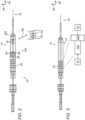
- Fig. 3 is a transparent orthogonal view schematically describing a phacoemulsification probe 12 of Fig. 1 (equipped with two independent piezoelectric vibrators), in accordance with an embodiment of the present invention.
- piezoelectric actuator 22 comprises two piezoelectric vibrators - crystals 122 and 222, and dual-channel piezoelectric drive system 100 excites each of the crystals independently in a selected resonant mode, typically at different frequencies, using drive-modules 30 1 and 30 2 .
- crystal 122 is vibrated in a longitudinal direction 62
- crystal 222 is vibrated in an axial direction 64.
- Crystals 122 and 222 are wired to be independently driven by two different voltages and frequencies to vibrate, for example, in two mutually orthogonal axes, longitudinal axis 62 and axial axis 64, respectively. To this end, crystals 122 and 222 are oriented mutually orthogonally one to the other. However, other mutually orthogonal axes are possible, e.g., such that the axes are rotated by a given angle relative to axes 62 and 64.
- piezoelectric actuator 22 may comprise more than two piezoelectric crystals.
- piezoelectric actuator 22 may comprise three independent piezoelectric crystals, each vibrating needle 16 at a spatially different direction (e.g. longitudinal, axial, and torsional).
- the three crystals are oriented orthogonally one to the other.
- the needle is vibrated by a piezoelectric vibrator comprising a stack of split-electrode single-crystal elements.
- the needle is vibrated a piezoelectric vibrator comprising a multi-crystal element made of angular sections.
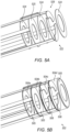
- Figs. 4A and 4B are schematic, pictorial illustrations of a stack 221 of split-electrode single-crystal elements and of a multi-crystal element 222 made of angular crystal sections, respectively, that can be used in phacoemulsification probe 12 of Fig. 1 , in accordance with embodiments of the present invention.
- split-electrode single-crystal stack 221 is assembled by stacking along longitudinal axis 62 four similar single-crystal piezo elements 410a, 410b, 410c, and 410d, which are angularly aligned.
- Each of piezo elements 410a, 410b, 410c, and 410d comprises a single-crystal piezo element having an annular cross section.
- each single-crystal element (with borders shown dotted) is disposed with three electrodes 411, 412 and 413.
- each of electrodes 411, 412 and 413 is applied to a respective approximately 120° angular section of the piezo element. Also shown are electrical leads 450 for driving the different electrodes of the different angular sections.
- processor 38 is configured to drive the various electrodes independently of one another, so as to apply any desired vibration pattern (e.g., a transverse mode of vibration along a transverse plane shown by axis 64). Typically, although not necessarily, processor 38 drives the electrodes of each angular section (across the stack of elements 410a-410d) with the same drive signal.
- each piezo element is disposed with a solid electrode 415 on the opposite side of the piezo element.
- the solid electrodes of the different piezo elements are used as common electrical ground, with electrical leads 465, that may be electrically connected one with the other.
- a single thick crystal could be used instead of a stack.
- a stack such as stack 410a-410d performs better, and is easier to manufacture.
- single-crystal elements 410a-410d are angularly aligned so that the disposed electrode sections are aligned rotationally to act together. To account for any misalignment during assembly the electrode sections are undersized with respect to the metalized surfaces of the crystal elements. Nevertheless, a calibration can be used for the driving waveforms, to correct any residual angular misalignment. Nevertheless, if the electrode spanned into another metalized region the probe may not perform as desired even using calibration.
- Fig. 4B illustrates an alternative embodiment.
- the piezoelectric vibrator comprises multi-crystal element 222 that is made of three angular crystal section elements 420a, 420b and 420c, which are glued together.
- Angular crystal section elements 420a, 420b and 420c have respective angular section electrodes 421, 422 and 423 disposed thereon. Also shown are respective electrical leads 431, 432 and 433 for driving the different angular section electrodes.
- a piezoelectric vibrator comprising a multi-crystal element made of angular sections, such as that of Fig. 4B , is described in U.S. Patent Application 17/231,450, titled “Compensating for Imperfect Behavior of Multi-Piezoelectric Crystal,” Filed April 15, 2021 , whose disclosure is incorporated herein by reference.
- piezoelectric vibrator shown in Figs. 4A and 4B were chosen purely for the sake of conceptual clarity. In general, other configurations may be used, such as, in Fig. 4A , a piezoelectric vibrator made of any two or more number of piezoelectric crystals that are stacked. In Fig, 4B , a piezoelectric vibrator made of any two or more number of piezoelectric crystals are sector-shaped. Thus, the number of angular sections per piezoelectric vibrator may differ from the shown 120-degrees (three sections) example.
- any respective two or more number of electrodes are patterned to energize separately the different piezoelectric crystals.
- Figs. 5A and 5B are schematic, pictorial illustrations of stacks 522 and 502 of single-crystal elements using, for driving circular, transverse, helical, and/or rotational motion, either a single split-electrode 526 or two disposed split-electrodes 506, respectively, in accordance with other embodiments of the present invention.
- Stacks 522 or 502 can be used, for example, in the phacoemulsification probe of Fig. 1 .
- two crystals are used for inducing a first motion (e.g., longitudinal motion) of the needle.
- a second motion e.g., rotational, transverse, helical, or circular.
- electrode serial numbers 1, 3, 5 are connected to electrical ground.
- the serial number 2 electrode i.e., electrode 525) is used for driving a first motion or movement (e.g., longitudinal)
- serial number 4 electrode is a split-electrode (split into 3 arcs) used for driving a second motion or movement (e.g., rotational, transverse, helical, or circular) of the needle.
- Driving electrodes (524,525,524,526,524) with respective polarities of (-,+,-,+,-), with - denoting ground, allows floating ground to be applied at the two ends and interface with the horn so the needle and handle are grounded. This solution also simplifies wiring.
- Fig. 5B shows piezoelectric crystals 504a-504d.
- Fig. 5B there are three full electrodes 505 using dashed lines.
- stack 502 is driven using two split-electrodes 506.
- Electrodes 506 are made by split metallization, which is typically metalized in a similar manner on both sides of crystal 504c. This configuration is beneficial as the manufacturer of the electrodes can utilize the same mask for both sides. Plating the crystal symmetrically with split-electrodes 506 also aids in assembly, as the rotation of the crystal can be seen from above as each piece is placed onto the horn.
- One of electrodes 506 may later be wired to ground (e.g., by electrically shortcutting the split electrodes of one of electrodes 506).
- Fig. 6 is a flow chart schematically describing a method for operating phacoemulsification apparatus 10 of Fig. 1 using the magnetic sensors on phacoemulsification probe 12, in accordance with an embodiment of the present invention.
- the algorithm carries out a process that begins with physician 15 inserting phacoemulsification needle 16 of probe 12 into a lens capsule 18 of an eye 20, at a needle insertion step 102.
- physician 15 activates probe 12, for example using a control over handle 121 or a foot pedal (not shown), to vibrate needle 16 in complex trajectory 44 comprising, for example, a combination of longitudinal, transverse, and/or torsional motion, at a needle vibrating step 104.
- processor 38 uses signals acquired by magnetic sensors 52, 54, 56, and 58, to measure an amplitude and direction of needle 16 vibration, at a feedback step 106, to use the measured amplitude and direction as inputs to a feedback loop.
- processor 38 adjusts frequencies of the drive signals such that the piezoelectric actuator vibrates at resonance, at a vibration controlling step 108, to have piezoelectric actuator 22 (comprising crystals 122 and 222) vibrate at the multiple (selected) resonant frequencies, so as to continue vibrating needle 16 in trajectory 44.
- processor 38 maximizes the amplitude feedback signal, and minimizes another feedback signal made of a norm of the required direction of vibration vs. the actual direction of vibration.
- Fig. 7 is a flow chart schematically describing a method for operating phacoemulsification apparatus 10 of Fig. 1 using the two independent piezoelectric vibrators of phacoemulsification probe 12, in accordance with an embodiment of the present invention.
- the algorithm carries out a process that begins with physician 15 inserting phacoemulsification needle 16 of probe 12 into a lens capsule 18 of an eye 20, at a needle insertion step 112.
- physician 15 activates probe 12, for example using a control over handle 121, to vibrate needle 16, in a needle vibrating step 114.
- processor 38 commands drive system 100, comprising drive-modules 30 1 and 30 2 , to generate drive signals to independently drive crystals 122 and 222 of the piezoelectric actuator, respectively, in a selected resonant mode of each crystal, typically at different frequencies.
- processor 38 crystals 122 and 222 adjust the frequencies of the drive signals generated by drive modules 30 1 and 30 2 , such that each of crystals 122 and 222 vibrate resonantly at its selected mode.
- the methods and systems described herein can also be used in other applications that may require a multi-channel piezoelectric resonant system to drive a moving member, such as in surface sensing microscopes that vibrate a tip.
Landscapes
- Health & Medical Sciences (AREA)
- Ophthalmology & Optometry (AREA)
- Life Sciences & Earth Sciences (AREA)
- Surgery (AREA)
- Engineering & Computer Science (AREA)
- General Health & Medical Sciences (AREA)
- Veterinary Medicine (AREA)
- Heart & Thoracic Surgery (AREA)
- Biomedical Technology (AREA)
- Animal Behavior & Ethology (AREA)
- Nuclear Medicine, Radiotherapy & Molecular Imaging (AREA)
- Public Health (AREA)
- Vascular Medicine (AREA)
- Robotics (AREA)
- Medical Informatics (AREA)
- Molecular Biology (AREA)
- Surgical Instruments (AREA)
- Eye Examination Apparatus (AREA)
- Investigating Or Analyzing Materials By The Use Of Magnetic Means (AREA)
- Investigating Or Analyzing Materials By The Use Of Ultrasonic Waves (AREA)
Abstract
Description
- This application claims the benefit of
U.S. Provisional Patent Application 63/028,098, filed May 21, 2020 - The present invention relates generally to piezoelectric-vibration-based medical devices, and particularly to phacoemulsification systems.
- A cataract is a clouding and hardening of the eye's natural lens, a structure which is positioned behind the cornea, iris and pupil. The lens is mostly made up of water and protein and as people age these proteins change and may begin to clump together obscuring portions of the lens. To correct this, a physician may recommend phacoemulsification cataract surgery. In the procedure, the surgeon makes a small incision in the sclera or cornea of the eye. Then a portion of the anterior surface of the lens capsule is removed to gain access to the cataract. The surgeon then uses a phacoemulsification probe, which has an ultrasonic handpiece with a needle. The tip of the needle vibrates at ultrasonic frequency to sculpt and emulsify the cataract while a pump aspirates particles and fluid from the eye through the tip. Aspirated fluids are replaced with irrigation of a balanced salt solution (BSS) to maintain the anterior chamber of the eye. After removing the cataract with phacoemulsification, the softer outer lens cortex is removed with suction. An intraocular lens (IOL) is then introduced into the empty lens capsule restoring the patient's vision.
- Various techniques to monitor ultrasonic vibration were proposed in the patent literature. For example, Chinese Patent Application Publication
CN 109029690 describes a multi-purpose ultrasound vibration amplitude measurement method and device of a vibrating tool head based on electromagnetic induction principle. The device includes two co-axial coils and a permanent magnet. As the tool head is moved with a given speed in a magnetic field generated by the permanent magnet, gained voltage and current signal are measured using the coils, and a faint mechanical oscillation of the head is detected and amplified, thereby greatly reducing measurement error. - As another example, German Patent Application Publication
DD 232755 - German Patent Application Publication
DE 3910200 describes a device for measuring ultrasonic amplitudes which are generated by an electromechanical resonance transducer which operates in the longitudinal vibration mode, and which are transmitted via a working tool into the effective medium or to the effective location, when an exact indication and evaluation of ultrasonic amplitudes is required for a working tool. According to the invention, the longitudinal oscillations of the transducer cause a periodic alteration of a resonant loop frequency of a RF-oscillator by means of a ring-shaped coil (coupling loop). The electrical alternating voltage produced is related to the actual ultrasonic amplitude occurring at the tip of the working tool. -
U.S. Patent Application Publication 2013/0314077 describes a displacement measurement device that includes: a metal object movable in a moving direction within a moving plane; a measurement coil arranged such that an opposite area of a measurement coil surface opposite to the moving plane is varied with a movement of the metal object; and a correction coil arranged such that an opposite area of a correction coil surface to the moving plane is not varied irrespective of the movement of the metal object. The measurement coil and the correction coil are arranged such that the measurement coil surface and the correction coil surface are not overlapped with each other with regard to a plane parallel to the moving plane but a range occupied by the measurement coil in a coordinate axis along the moving direction and a range occupied by the correction coil in the coordinate axis are overlapped with each other. -
U.S. Patent 9,018,887 - Various techniques to vibrate a phacoemulsification needle of a probe were proposed in the patent literature. For example,
U.S. Patent 6,402,769 describes a torsional ultrasound handpiece having at least one set of piezoelectric elements. The piezoelectric elements are constructed of segments that produce both longitudinal and torsional motion. An appropriate ultrasound driver drives the set of elements at the respective resonant frequencies to product longitudinal vibration and torsional oscillation. In an embodiment, two different sets of crystals vibrate ultrasonically in response to a signal generated by ultrasound generator. One set of crystals is polarized to produce torsional motion. Another set of crystals is polarized to produce longitudinal motion. - As another example,
U.S. Patent 8,303,613 describes a Langevin transducer horn that uses split electroding or selective electroding of transducer elements and phase relationships of the voltages applied thereto to determine the relative longitudinal and flexural/transverse motion induced in the tip of the horn. In an embodiment, an ultrasonic surgical instrument is provided, that includes a piezoelectric transducer element attached to the horn such that excitation of the piezoelectric element using one of the above electroding causes vibration of a working member of the horn. - An embodiment of the present invention that is described hereinafter provides a phacoemulsification device including a phacoemulsification probe and a processor. The phacoemulsification probe includes (a) a piezoelectric crystal configured to vibrate in response to a drive signal, (b) a needle configured to be inserted into a lens capsule of an eye and to be vibrated by the piezoelectric crystal, and (c) a set of magnetic-field components. The set includes (i) one or more magnetic-field generators configured to generate a magnetic field, and (ii) one or more magnetic-field sensors configured to sense the magnetic field. At least one of the magnetic-field components is coupled to vibrate with the needle and at least one other of the magnetic-field components is isolated from vibration of the needle, thereby causing the magnetic-field sensors to output signals indicative of the vibration. The processor is configured to adaptively adjust a frequency of the drive signal so as to vibrate the needle at a resonant frequency of the piezoelectric crystal.
- In some embodiments, the outputted signals are indicative of at least one of an amplitude and a direction of the vibration of the needle.
- In some embodiments, at least one of the magnetic-field components in the set includes a coil wound around a distal end of a horn of the phacoemulsification probe.
- In an embodiment, at least one of the magnetic-field components in the set is placed off a longitudinal axis of a horn of the phacoemulsification probe.
- In an embodiment, the phacoemulsification probe further includes a horn, wherein the horn is coupled with the needle, and wherein at least one of the magnetic-field components is placed off a longitudinal axis of the horn.
- In another embodiment, the magnetic-field components include one or more permanent magnets.
- In some embodiments, the processor is further configured to calculate a derivative of the outputted signals with respect to time, and, in response to detecting that the derivative exceeds a given threshold, indicate to a user that the needle is engaging ocular media.
- There is additionally provided, in accordance with another embodiment of the present invention, a phacoemulsification device including a phacoemulsification probe and a processor. The phacoemulsification probe includes two or more piezoelectric crystals, each excited in a single respective resonant mode in response to a respective drive signal. The phacoemulsification probe further includes a needle configured to be inserted into a lens capsule of an eye and to be vibrated by the two or more piezoelectric crystals. The processor is configured to adaptively adjust a respective frequency of each drive signal so as to excite each of the two or more piezoelectric crystals in the single respective resonant mode only.
- In some embodiments, at least two of the piezoelectric crystals are mutually orthogonal to one another.
- In an embodiment, the two or more piezoelectric crystals are stacked on one another along a longitudinal axis of the phacoemulsification probe, and the phacoemulsification device further includes, for each piezoelectric crystal in the stack, multiple electrodes that are configured, when driven by the processor, to excite multiple respective angular sections of the piezoelectric crystal.
- In another embodiment, the two or more piezoelectric crystals are sector-shaped and are attached to one another surrounding a longitudinal axis of the phacoemulsification probe.
- In some embodiments, the processor is configured to excite the two or more piezoelectric crystals so as to vibrate the needle in a circular, elliptical, or helical trajectory around a longitudinal axis of the phacoemulsification probe.
- In some embodiments, the processor is configured to adaptively adjust the frequency of each drive signal independently of any other drive signal.
- In an embodiment, the phacoemulsification probe further includes a horn, the horn is coupled with the needle, and the two or more piezoelectric crystals are coupled with the horn.
- There is further provided, in accordance with another embodiment of the present invention, a phacoemulsification method. The method includes energizing a piezoelectric crystal of the phacoemulsification probe using a drive signal, and vibrating a needle of the phacoemulsification probe by the energized piezoelectric crystal. Signals, which are indicative of vibration of the needle, are output using a set of magnetic-field components. The set includes (i) at least one magnetic-field generator configured to generate a magnetic field, and (ii) at least one magnetic-field sensor configured to sense the magnetic field. One of the at least one of the magnetic-field generator or the at least one magnetic-field sensor is coupled with the needle to vibrate the needle and wherein the other one of the at least one of the magnetic-field generator or the at least one magnetic-field sensor is isolated from vibration of the needle. A frequency of the drive signal is adaptively adjusted so as to vibrate the needle at a resonant frequency of the piezoelectric crystal.
- There is further yet provided, in accordance with another embodiment of the present invention, a method for operating a phacoemulsification probe. The method includes exciting two or more piezoelectric crystals of the phacoemulsification probe, each piezoelectric crystal excited in a single resonant mode using a respective drive signal. A needle of the phacoemulsification probe is vibrated by the two or more piezoelectric crystals. A respective frequency of each drive signal is adaptively adjusted, so as to excite each of the two or more piezoelectric crystals in the single respective resonant mode only.
- There is further provided, in accordance with another embodiment of the present invention, a phacoemulsification device including a phacoemulsification probe and a processor. The phacoemulsification probe includes (a) two or more piezoelectric crystals, each crystal excited in response to a respective drive signal, and (b) a needle configured to be inserted into a lens capsule of an eye and to be vibrated by the two or more piezoelectric crystals. The processor is configured to (i) vibrate the needle in a longitudinal vibration mode, (ii) in response to sensing an occlusion of the needle, switch to vibrating the needle in a transverse, circular, elliptical, or helical vibration mode. Further aspects of vibrating a needle in longitudinal and non-longitudinal modes are described in
U.S. Patent 10,363,166 - There is furthermore provided, in accordance with another embodiment of the present invention, a method for operating a phacoemulsification probe, the method including energizing two or more piezoelectric crystals of the phacoemulsification probe using respective drive signals. A needle of the phacoemulsification probe is vibrated by the energized piezoelectric crystals in a longitudinal vibration mode. In response to sensing an occlusion, a switch is made to vibrate the needle in a transverse vibration mode.
- The present invention will be more fully understood from the following detailed description of the embodiments thereof, taken together with the drawings in which:
-
-
Fig. 1 is a pictorial view, along with a block diagram, of a phacoemulsification apparatus comprising a phacoemulsification probe comprising magnetic sensors and two independent piezoelectric vibrators, in accordance with an embodiment of the present invention; -
Fig. 2 is a transparent orthogonal view schematically describing a phacoemulsification probe ofFig. 1 (equipped with two sets of magnetic sensors), in accordance with an embodiment of the present invention; -
Fig. 3 is a transparent orthogonal view schematically describing a phacoemulsification probe ofFig. 1 (equipped with two independent piezoelectric vibrators), in accordance with an embodiment of the present invention; -
Figs. 4A and 4B are schematic, pictorial illustrations of a stack of split-electrode single-crystal elements and of a multi-crystal element made of angular crystal sections, respectively, that can be used in the phacoemulsification probe ofFig. 1 , in accordance with embodiments of the present invention; -
Figs. 5A and 5B are schematic, pictorial illustrations of a stack of single-crystal elements using either a single split-electrode or two split-electrodes, respectively, in accordance with other embodiments of the present invention; -
Fig. 6 is a flow chart schematically describing a method for operating the phacoemulsification apparatus ofFig. 1 using the magnetic sensors on the phacoemulsification probe, in accordance with an embodiment of the present invention; and -
Fig. 7 is a flow chart schematically describing a method for operating the phacoemulsification apparatus ofFig. 1 using the two independent piezoelectric vibrators of the phacoemulsification probe, in accordance with an embodiment of the present invention. - A phacoemulsification system typically drives a piezoelectric actuator fitted in a phacoemulsification probe ("handpiece") to vibrate a needle during a cataract procedure. The piezoelectric actuator of the phacoemulsification probe may be designed to vibrate in one or more resonant modes of its one or more respective piezoelectric crystals, where each mode has a given "natural" resonant frequency. For example, a multi-resonance mode might yield a complex vibration profile that combines longitudinal, transverse, and torsion vibrations, each with its own resonant frequency. Such a mode may have a complex customizable vibration profile that may allow a physician to better perform phacoemulsification.
- In order to vibrate a piezoelectric crystal efficiently, the frequency of the respective drive signal should match the resonance frequency of the piezoelectric crystal. The resonance frequency of the crystal, however, may change due to mechanical load on the needle, such as load applied by the ocular media in which the needle vibrates, and/or due to varying crystal temperature. Moreover, interactions among the two or more different vibration modes may further change their natural resonance frequencies. The actual parameters of the vibration, e.g., an amplitude and direction of the needle motion, cannot therefore be determined from the driving frequency. If the drive signal remains at a constant frequency (e.g., matching the natural resonance frequency of the mechanically-unloaded crystal) the vibration efficiency will deteriorate in real life operation.
- In particular, the changing (e.g., drifting) frequency results in reduced vibration amplitude, while the increased heat may cause damage to the eye, or discomfort to the surgeon holding the probe.
- Embodiments of the present invention that are described hereinafter provide improved methods and systems for driving one or more piezoelectric crystals in a phacoemulsification probe ("handpiece"). The disclosed techniques measure the actual vibration, and in response adapt one or more frequencies of one or more drive signals that drive the one or more piezoelectric crystals. For example, some disclosed techniques measure the amplitude of vibration, and adapt the frequencies of the drive signals to maximize it. In this manner, the one or more frequencies of the drive signals continuously track the actual one or more resonance frequencies of the respective one or more crystals.
- In an embodiment, a phacoemulsification device is provided, that includes a phacoemulsification probe and a processor. The phacoemulsification probe includes (a) a piezoelectric crystal configured to vibrate in response to a drive signal, (b) a needle configured for insertion into a lens capsule of an eye and to be vibrated by the piezoelectric crystal, and (c) a set of magnetic-field components, wherein the set comprises (i) one or more magnetic-field generators, such as transmit coils, configured to generate a magnetic field, and (ii) one or more magnetic-field sensors, such as receive coils, configured to sense the magnetic field, wherein at least one of the magnetic-field components is configured to vibrate with the needle and at least one other of the magnetic-field components is isolated from vibration of the needle, thereby causing the magnetic-field sensors to output signals indicative of the vibration. The outputted signals are typically indicative of at least one of an amplitude and a direction of vibration of the needle. The processor is configured to adaptively adjust a frequency of the drive signal so as to vibrate the needle at a resonant frequency of the piezoelectric crystal.
- In one embodiment, the vibration amplitude is measured by coupling one or more RF transmit coils and one or more RF receive coils to a horn of the probe, at a distal end and a proximal end of the horn, respectively. The horn is mechanically coupled to one or more piezoelectric crystals which vibrate the horn. The horn, in turn, vibrates the needle. In one example, the one or more RF transmit coils and the one or more RF receive coils are wound around the horn at its opposite ends. The vibration amplitude causes changes in the magnetic flux through the one or more receive coils, which is indicative of an amount of the receive coil's deflection amplitude relative to a longitudinal axis of the probe (The one or more RF transmit coils are coupled such they are not vibrating).
- In another embodiment, a subassembly (e.g., a set) of three receive coils is placed off the horn's axis of symmetry (i.e., off the horn's longitudinal axis). For example, the three coils may be spaced azimuthally 120° apart at a same radial distance from the axis. In that way, regardless of the vibration direction, the coils generate a sufficient alternating current (AC) signal (due to experiencing a change in magnetic flux) indicative of the vibration amplitude. Moreover, the three signals are correlated, which enables improvement of the accuracy of the measured vibration amplitude.
- In general, a first set of coils (that can be a single coil or any number of coils) is mechanically coupled to the needle, so that they vibrate in synchrony with the vibrated needle. A second set of coils (that can be a single coil or any number of coils) is coupled to be stationary, i.e., mechanically isolated from the vibration of the needle. For example, coils of the second subassembly (e.g., set) are statically disposed off a longitudinal axis of the horn (e.g., equiangularly over a perimeter of a proximal section of the horn), with the coils being parallel to each other and to the coils of the first set, but with any of the coils not being coaxial with another. Alternatively, a second set of coils may be located at a nodal location where there is no motion. Such arrangement results in relative motion between the first and second sets of coils as the needle vibrates. As a result, at least one of the coils experiencing a change in a magnetic flux induced due to needle vibration outputs a signal indicative of at least one of an amplitude and direction of vibration of the needle.
- In a further embodiment, a processor calculates a derivative of the outputted signal peak value (caused by needle vibration) with respect to time. If the change in the derivative exceeds a given threshold, the processor concludes that the needle is engaging ocular media (i.e., comes to contact with the cataract lens). A relevant threshold value may be determined in a lab, for example as a change in the derivative caused by inserting the needle into water. For example, an abrupt change in vibration amplitude, (e.g., transient reduction in vibration amplitude, having a predetermined temporal width) indicates that a perturbation to the vibrating needle has just occurred by the needle being moved from air into ocular media.
- Furthermore, the above-described set of three coils enables the measurement of a direction of the needle vibration. Readings from the three receive coils provide values for the magnitude and direction of the deflection of the needle vibration. These parameters can be used as feedback values for a control loop to maintain the modes of vibration at resonance. For example, the control loop may minimizes a direction indicative feedback value defined by a norm. Such norm calculates the required direction of vibration vs. the actual direction of vibration (i.e., the control loop acts to minimize such a norm).
- The coils are typically operated at 200 kHz, while the resonant vibration frequency is typically ~40 kHz, so there is no interference between the sensing and the driving signals. The coils are operated at a given frequency for a given digital sampling rate. Using a higher sampling frequency of the coil signals allows the two frequencies to be closer one to the other. The analog signals that the one or more transmit coils output are measured using an electronic circuitry and typically subsequently converted to digital signals using an Analog/Digital (A/D) converter. To ensure accurate results, the A/D converter applies a high sampling rate of at least 400 kHz, and possibly up to about 1MHz and more.
- In another embodiment, one or more permanent magnets are used as a transmitter instead of using an RF transmit coil. The one or more magnets are oriented (e.g., the magnetic field lines that the one or more permanent magnets generate are designed such that, as the one or more permanent magnets vibrate on the horn, their vibration induces an AC signal in each of the one or more receive coils where the induced AC signal is indicative of the vibration.
- In yet another embodiment the one or more permanent magnets are fixed (e.g., at a proximal base of the horn or at a nodal point), and the receive coils are coupled to a distal end of the horn where they vibrate. Again, the one or more permanent magnets are configured to induce an AC field in each vibrating receive coil indicative of the vibration amplitude and direction.
- As noted above, phacoemulsification may use two or more modes of needle vibration in order to carve up the cataract lens of the eye. Such multiple modes may be achieved, for example, by exciting a single piezoelectric crystal with multiple drive frequencies, so that the crystal simultaneously vibrates in resonance in the multiple modes. However, as noted above, the crystal's driving signal frequencies may shift off resonance due to the mechanical coupling between the modes. In addition, the amount of coupling changes, for example, as the crystal temperature changes. Thus, it is difficult to maintain all of the modes in resonance.
- Therefore, some embodiments of the present invention that are described hereinafter vibrate the needle using two or more piezoelectric crystals. Each of the crystals is independently driven in only one selected resonant mode. Typically, the drive signal frequency of each mode is different. In an embodiment, the two or more piezoelectric crystals are oriented orthogonally one to the other (up to three crystals).
- Some embodiments provide individual processor-controlled drive modules, described below, to drive each a respective resonant-frequency mode of vibration of the two or more piezoelectric crystals. Requiring each crystal to vibrate only in one mode reduces the interaction between the modes, and hence makes it much easier to generate the required vibrations.
- In one embodiment, the needle is vibrated by a piezoelectric vibrator comprising a split-electrode single-crystal stack. In another embodiment, the needle is vibrated a piezoelectric vibrator comprising multi-crystal made of angular sections. These two embodiments of a piezoelectric vibrator can assist in clearing an occlusion of the needle. For example, under normal conditions (i.e., in absence of an occlusion) the processor may vibrate the needle using longitudinal vibration. In response to receiving an indication that the inlet of the needle is occluded by a particle (e.g., an indication of low pressure from a pressure sensor on the aspiration line), the processor may switch the needle motion from longitudinal to another needle motion or movement (e.g., rotational, transverse, circular, helical, etc.) to shake the particle free. Switching modes may be accomplished by adding some transverse movement to an already existing longitudinal movement. One such possibility is to create a helical movement. Once the particle is free and the system senses no occlusion, the processor may switch back to vibrate the needle using longitudinal motion.
- In one embodiment part of the crystal stack is configured to deliver longitudinal motion and a separate part of the crystal stack is configured to deliver transverse or rotational movement.
-
Fig. 1 is a pictorial view, along with a block diagram, of aphacoemulsification apparatus 10 comprising aphacoemulsification probe 12 comprising magnetic sensors and two independent piezoelectric vibrators (the sensors and the piezoelectric vibrators are described inFigs. 2 and 3 , respectively), in accordance with an embodiment of the present invention. As seen in the pictorial view ofphacoemulsification apparatus 10, and the block diagram ininset 25, it includes aphacoemulsification probe 12 comprising aneedle 16 configured for insertion into alens capsule 18 of aneye 20 of a patient 19 by aphysician 15.Needle 16 is coupled with ahorn 14 comprised inprobe 12, and is shown ininset 25 as a straight needle. However, any suitable needle may be used with thephacoemulsification probe 12, for example, a curved or bent tip needle commercially available from Johnson & Johnson Surgical Vision, Santa Ana, CA, USA. - A
piezoelectric actuator 22 insideprobe 12 is configured to vibratehorn 14 andneedle 16 in one or more resonant vibration modes of the combined horn and needle element. The vibration ofneedle 16 is used to break a cataract into small pieces during the phacoemulsification procedure. - The distal end of
horn 14 deflects during vibration, and the amplitude and direction of this deflection are used by the disclosed technique to give indications of the actual vibration amplitude and direction ofneedle 16. The indications are used to control piezoelectric vibration such thatneedle 16 is continuously vibrated at the resonant (selected) modes. - In the shown embodiment,
console 28 comprises a dual-channelpiezoelectric drive system 100 comprising drive-modules 301 and 302, each coupled, using electrical wiring running incable 33, with each one of two piezoelectric crystals (shown inFig. 3 ) ofactuator 22. Drive modules 301 and 302 are controlled by aprocessor 38 and convey processor-controlled driving signals viacable 33 to adjust frequencies of a multi-resonance mode ofpiezoelectric actuator 22 to maintainneedle 16 at maximal vibration amplitude of atrajectory 44. Each of the drive modules may be realized in hardware or software, for example, in a proportional-integral-derivative (PID) control architecture. - The direction and amplitude of
needle 16 displacement are estimated using magnetic sensors disposed on distal and proximal portions ofhorn 14, as described inFig. 2 . Driving signals and responsively sensed signals, collectively called hereinafter "signals 34," are conveyed overcable 33 between amagnetic sensing module 39 and the magnetic sensors (shown inFig. 2 and 3 ), wheremodule 39 is controlled by aprocessor 38, which is also provided with the sensed signals.Processor 38 uses the signals to estimate the direction and amplitude ofneedle 16, and correspondingly to command piezoelectric drive modules to maintainneedle 16 vibration at resonance. - The operation of a magnetic sensing assembly and its use in tissue-tip pressure sensing in the context of probe-based procedures are described in
U.S. Patent Application Publication 2014/0024969 , which is assigned to the assignee of the present patent application, which document is incorporated by reference.U.S. Patent Application Publication 2014/0024969 describes a joint that couples a distal tip to a distal end of the probe. A joint sensor, contained within the probe, senses a position of the distal tip relative to the distal end of the probe, including axial displacement and angular deflection. The joint sensor includes first and second subassemblies, which are disposed within the probe on opposite, respective sides of the joint and each include one or more magnetic sensors, such as coils, to provide the accurate pressure sensing. - Using a switching
circuitry 41,processor 38 is further configured to connect drive-modules 301 and/or 302 to vibrateneedle 16 in one of several prespecified trajectories. - Some or all of the functions of
processor 38 may be combined in a single physical component or, alternatively, implemented using multiple physical components. These physical components may comprise hard-wired or programmable devices, or a combination of the two. In some embodiments, at least some of the functions ofprocessor 38 may be carried out by suitable software stored in amemory 35. This software may be downloaded to a device in electronic form, over a network, for example. Alternatively, or additionally, the software may be stored in tangible, non-transitory computer-readable storage media, such as optical, magnetic, or electronic memory. -
Processor 38 may receive user-based commands via auser interface 40, which may include setting a vibration mode and/or frequency of thepiezoelectric actuator 22, adjusting the vibration mode and/or frequency of thepiezoelectric actuator 22, setting or adjusting a stroke amplitude of theneedle 16, setting or adjusting an irrigation and/or aspiration rate of thepumping sub-system 26. Additionally, or alternatively,processor 38 may receive user-based commands from controls located inhandle 121, to, for example,select trajectory 44 or another trajectory forneedle 16. - In the shown embodiment, during the phacoemulsification procedure, a
pumping sub-system 24 comprised in aconsole 28 pumps irrigation fluid from an irrigation reservoir toneedle 16 to irrigate the eye. The fluid is pumped via atubing line 43 running from theconsole 28 to theprobe 12. Waste matter (e.g., emulsified parts of the cataract) and eye fluid are aspirated vianeedle 16 to the collection receptacle by apumping sub-system 26 also comprised inconsole 28 and using anothertubing line 46 running fromprobe 12 to console 28. - As seen in
Fig. 1 ,processor 38 may present results of the procedure on adisplay 36. In an embodiment,user interface 40 anddisplay 36 may be one and the same such as a touch screen graphical user interface. - The apparatus shown in
Fig. 1 may include further elements, which are omitted for clarity of presentation. For example,physician 15 typically performs the procedure using a stereo microscope or magnifying glasses, neither of which are shown.Physician 15 may use other surgical tools in addition toprobe 12, which are also not shown, in order to maintain clarity and simplicity of presentation. -
Fig. 2 is a transparent orthogonal view schematically describing aphacoemulsification probe 12 ofFig. 1 (equipped with twosubassemblies coils needle 16, including its displacement along a planned trajectory, such as trajectory 44 (which may also represent a simple axial trajectory) and its azimuthal direction of deflection. These coils are one type of coils that are used to generate magnetic flux or detect oscillating magnetic flux, that may be used in embodiments of the present invention. - The four coils disposed in
probe 12 are divided between two subassemblies on opposite sides ofhorn 14. One subassembly comprises a single coil, 52, which is coupled with or disposed over a distal end ofhorn 14, and thereforecoil 52 vibrates withhorn 14.Coil 52 is driven by a current via wiring running incable 33 frommodule 39 to generate a magnetic field. This field is received by a second subassembly, comprising coils 54, 56, and 58, that are fixed relative to probe 12 (i.e., not vibrating with horn 14) and are located in a section of the probe that is spaced axially apart fromcoil 52. (The term "axial," as used in the context of the present patent application and in the claims, refers to the direction oflongitudinal axis 62 ofhorn 14 at resting position. An axial plane is a plane perpendicular tolongitudinal axis 62, and an axial section is a portion of the probe contained between two axial planes.)Coils coils coil 52. The electrical signals are conveyed by wiring viacable 33 tomodule 39 and from there toprocessor 38, which processes the signals in order to measure the axial displacement and angular deflection ofcoil 52 and from those ofneedle 16. -
Coils probe 12 at different radial axis (64) locations. (The term "radial" refers to axial coordinates.Axis 64 is also used after to define a transverse direction of vibration, as opposed to a longitudinal direction of vibration along axis 62). Specifically, in this embodiment, coils 54, 56, and 58 are all located in the same axial plane at different azimuthal angles aboutprobe axis 62. For example, the three coils may be spaced azimuthally 120° apart at the same radial distance from the axis. - The axes of symmetry of
coils coil 52, and the signals vary strongly with the distances ofcoils coil 52. (Alternatively, the axis ofcoil 52 and/or coils 54, 56, and 58 may be angled relative to the probe (e.g., of horn 14) axis, as long as the coil axes have a sufficient parallel component in order to give substantial signals.) - Angular deflection of a
distal end horn 14 gives rise to a differential change in the signal output bycoils coil 52. Typically, coils, 56, and 58 are each staggered (i.e., laterally displaced) by several millimeters fromcoil 52. -
Processor 38 analyzes the signal output ofcoils needle 16. The difference of the changes gives the deflection. The vector direction of the difference gives an indication of the bend direction. A suitable calibration procedure may be used to measure the precise dependence of the signals on deflection ofneedle 16. -
Coils horn 14 is typically about 40 kHz, and thus there is no interference. The transmit coil signals are typically measured digitally, in an A/D converter, which should have a high sampling rate of at least 400 kHz to ensure good results. - Various other configurations of the coils in the sensing subassemblies may also be used, alternatively to the configuration shown and described above. For example, the positions of the subassemblies may be reversed, so that that field generator coil is fixed, and the sensor coils vibrate with
horn 14. As another alternative, coils 54, 56, and 58 may be driven as field generators (using time- and/or frequency-multiplexing to distinguish the fields), whilecoil 52 serves as the sensor. The sizes and numbers of the coils inFig. 2 are shown only by way of example, and larger or smaller numbers of coils may similarly be used, in various different positions, so long as one of the subassemblies comprises at least two coils, in different radial positions, to allow differential measurement of joint deflection. - More generally put, the various types of magnetic-field generators (e.g., TX coils or permanent magnets) and magnetic-field sensors (RX coils) are referred to herein collectively as a set of "magnetic-field components." The disclosed techniques can be carried out using any other suitable configuration of a set of magnetic-field components, in which (i) one or more magnetic-field generators are configured to generate a magnetic field, and (ii) one or more magnetic-field sensors are configured to sense the magnetic field, (iii) at least one of the magnetic-field components is coupled to vibrate with the needle, and (iv) at least one other of the magnetic-field components is isolated from vibration of the needle. In such an arrangement, the magnetic-field sensors would output signals indicative of the vibration, enabling
processor 38 to adapt the drive-signal frequency. - Prior calibration of the relation between deflection of
needle 16 and movement ofhorn 14 may be used byprocessor 38 to translate the coil signals into terms of deflection amplitude and direction. The deflection reading is insensitive to temperature variations and free of drift, unlike piezoelectric sensors, for example. Because of the high sensitivity toneedle 16 motion that is afforded by the arrangement ofcoils processor 38 can measure small displacements and deflections with high precision. Therefore, horn 14 can be made relatively stiff, andprocessor 38 will still be able to sense and measure accurately the deflection ofneedle 16. The stiffness of the horn makes it easier for the operator to maneuver and control the phacoemulsification probe. - In another embodiment,
coil 52 is replaced (88) with apermanent magnet 55, which, becausemagnet 55 vibrates (being attached to a distal end of a horn 144), the vibratingpermanent magnet 55 induces alternating (e.g., oscillating) magnetic flux incoils needle 16 vibration amplitude and direction. In this case, coils 52, 54, 56, and 58 are typically operated at the resonant ultrasound frequency ofhorn 14 that is typically about 40 kHz, and an interference due to piezo driving signals is addressed inmodule 39 using appropriate electronic means (e.g., using phase demodulation, assuming that piezo displacement signals lag in a predefined phase relative to piezo-driving signals). The use ofpermanent magnet 55 may simplifyprobe 12, and may be worth the effort of overcoming any electronic interference. - The example illustration shown in
Fig. 2 is chosen purely for the sake of conceptual clarity.Fig. 2 shows only parts relevant to embodiments of the present invention. Other elements, such as wiring of the magnetic sensors, are omitted. -
Fig. 3 is a transparent orthogonal view schematically describing aphacoemulsification probe 12 ofFig. 1 (equipped with two independent piezoelectric vibrators), in accordance with an embodiment of the present invention. - As seen,
piezoelectric actuator 22 comprises two piezoelectric vibrators -crystals piezoelectric drive system 100 excites each of the crystals independently in a selected resonant mode, typically at different frequencies, using drive-modules 301 and 302. In the shown example,crystal 122 is vibrated in alongitudinal direction 62, whereascrystal 222 is vibrated in anaxial direction 64. - By limiting the requirement from each of
crystals -
Crystals longitudinal axis 62 andaxial axis 64, respectively. To this end,crystals axes - While
Fig. 3 shows apiezoelectric actuator 22 comprising two piezoelectric crystals, in general,piezoelectric actuator 22 may comprise more than two piezoelectric crystals. For example,piezoelectric actuator 22 may comprise three independent piezoelectric crystals, each vibratingneedle 16 at a spatially different direction (e.g. longitudinal, axial, and torsional). In another embodiment, the three crystals are oriented orthogonally one to the other. - As noted above, in one embodiment, shown in
Fig. 4A below, the needle is vibrated by a piezoelectric vibrator comprising a stack of split-electrode single-crystal elements. In another embodiment, shown inFig. 4B below, the needle is vibrated a piezoelectric vibrator comprising a multi-crystal element made of angular sections. -
Figs. 4A and 4B are schematic, pictorial illustrations of astack 221 of split-electrode single-crystal elements and of amulti-crystal element 222 made of angular crystal sections, respectively, that can be used inphacoemulsification probe 12 ofFig. 1 , in accordance with embodiments of the present invention. - As seen in
Fig. 4A , split-electrode single-crystal stack 221 is assembled by stacking alonglongitudinal axis 62 four similar single-crystalpiezo elements piezo elements Fig. 4A , each single-crystal element (with borders shown dotted) is disposed with threeelectrodes electrodes electrical leads 450 for driving the different electrodes of the different angular sections. In some embodiments,processor 38 is configured to drive the various electrodes independently of one another, so as to apply any desired vibration pattern (e.g., a transverse mode of vibration along a transverse plane shown by axis 64). Typically, although not necessarily,processor 38 drives the electrodes of each angular section (across the stack ofelements 410a-410d) with the same drive signal. - To drive
piezo elements solid electrode 415 on the opposite side of the piezo element. In an embodiment, the solid electrodes of the different piezo elements are used as common electrical ground, withelectrical leads 465, that may be electrically connected one with the other. - In principle, a single thick crystal could be used instead of a stack. In practice, however, a stack such as
stack 410a-410d performs better, and is easier to manufacture. As noted above, single-crystal elements 410a-410d are angularly aligned so that the disposed electrode sections are aligned rotationally to act together. To account for any misalignment during assembly the electrode sections are undersized with respect to the metalized surfaces of the crystal elements. Nevertheless, a calibration can be used for the driving waveforms, to correct any residual angular misalignment. Nevertheless, if the electrode spanned into another metalized region the probe may not perform as desired even using calibration. - Benefits realized the disclosed configuration include:
- 1) Stacking of multiple single crystals is simpler and achieves better performance than stacking triplets of sector-shaped crystals, e.g., because the top and bottom crystal surfaces are more planar and better aligned.
- 2) Since each layer of the stack is a single monolithic crystal, there is no need for spacers that may be needed in sector-shaped assemblies.
- 3) Since each crystal has a well-controlled inner diameter, the risk of placement errors that cause heating is minimized.
- 4) Since the number of parts in the stack is small, relative to a stack made of triplets of sector-shaped crystals, the assembly process is simple.
- 5) As the crystals are electrically in parallel with respect to the system, this allows for operation at a lower voltage which makes system and device design easier.
-
Fig. 4B illustrates an alternative embodiment. In this example, the piezoelectric vibrator comprisesmulti-crystal element 222 that is made of three angularcrystal section elements crystal section elements angular section electrodes electrical leads - A piezoelectric vibrator comprising a multi-crystal element made of angular sections, such as that of
Fig. 4B , is described inU.S. Patent Application 17/231,450, titled "Compensating for Imperfect Behavior of Multi-Piezoelectric Crystal," Filed April 15, 2021 - The examples of piezoelectric vibrator shown in
Figs. 4A and 4B were chosen purely for the sake of conceptual clarity. In general, other configurations may be used, such as, inFig. 4A , a piezoelectric vibrator made of any two or more number of piezoelectric crystals that are stacked. InFig, 4B , a piezoelectric vibrator made of any two or more number of piezoelectric crystals are sector-shaped. Thus, the number of angular sections per piezoelectric vibrator may differ from the shown 120-degrees (three sections) example. - Accordingly for
Figs. 4A and 4B , any respective two or more number of electrodes are patterned to energize separately the different piezoelectric crystals. -
Figs. 5A and 5B are schematic, pictorial illustrations ofstacks electrode 526 or two disposed split-electrodes 506, respectively, in accordance with other embodiments of the present invention. -
Stacks Fig. 1 . - In stacks 522 and 502, two crystals (shown in
Fig. 5B ) are used for inducing a first motion (e.g., longitudinal motion) of the needle. Two other crystals (also shown inFig. 5B ) are used for inducing a second motion (e.g., rotational, transverse, helical, or circular). - In
Fig. 5A , of the five electrodes shown, from left to right, electrode serial numbers 1, 3, 5 (i.e., electrodes 524) are connected to electrical ground. The serial number 2 electrode (i.e., electrode 525) is used for driving a first motion or movement (e.g., longitudinal) and serial number 4 electrode (labeled 526) is a split-electrode (split into 3 arcs) used for driving a second motion or movement (e.g., rotational, transverse, helical, or circular) of the needle. - Driving electrodes (524,525,524,526,524) with respective polarities of (-,+,-,+,-), with - denoting ground, allows floating ground to be applied at the two ends and interface with the horn so the needle and handle are grounded. This solution also simplifies wiring.
-
Fig. 5B showspiezoelectric crystals 504a-504d. InFig. 5B , there are threefull electrodes 505 using dashed lines. As seen, stack 502 is driven using two split-electrodes 506.Electrodes 506 are made by split metallization, which is typically metalized in a similar manner on both sides ofcrystal 504c. This configuration is beneficial as the manufacturer of the electrodes can utilize the same mask for both sides. Plating the crystal symmetrically with split-electrodes 506 also aids in assembly, as the rotation of the crystal can be seen from above as each piece is placed onto the horn. One ofelectrodes 506 may later be wired to ground (e.g., by electrically shortcutting the split electrodes of one of electrodes 506). -
Fig. 6 is a flow chart schematically describing a method for operatingphacoemulsification apparatus 10 ofFig. 1 using the magnetic sensors onphacoemulsification probe 12, in accordance with an embodiment of the present invention. The algorithm, according to the presented embodiment, carries out a process that begins withphysician 15 insertingphacoemulsification needle 16 ofprobe 12 into alens capsule 18 of aneye 20, at aneedle insertion step 102. - Next,
physician 15 activatesprobe 12, for example using a control overhandle 121 or a foot pedal (not shown), to vibrateneedle 16 incomplex trajectory 44 comprising, for example, a combination of longitudinal, transverse, and/or torsional motion, at aneedle vibrating step 104. - Using signals acquired by
magnetic sensors processor 38 measures an amplitude and direction ofneedle 16 vibration, at afeedback step 106, to use the measured amplitude and direction as inputs to a feedback loop. - Finally, using the feedback loop,
processor 38 adjusts frequencies of the drive signals such that the piezoelectric actuator vibrates at resonance, at avibration controlling step 108, to have piezoelectric actuator 22 (comprisingcrystals 122 and 222) vibrate at the multiple (selected) resonant frequencies, so as to continue vibratingneedle 16 intrajectory 44. For example, in order to maintain vibration in resonance,processor 38 maximizes the amplitude feedback signal, and minimizes another feedback signal made of a norm of the required direction of vibration vs. the actual direction of vibration. -
Fig. 7 is a flow chart schematically describing a method for operatingphacoemulsification apparatus 10 ofFig. 1 using the two independent piezoelectric vibrators ofphacoemulsification probe 12, in accordance with an embodiment of the present invention. The algorithm, according to the presented embodiment, carries out a process that begins withphysician 15 insertingphacoemulsification needle 16 ofprobe 12 into alens capsule 18 of aneye 20, at aneedle insertion step 112. - Next,
physician 15 activatesprobe 12, for example using a control overhandle 121, to vibrateneedle 16, in aneedle vibrating step 114. In response,processor 38 commands drivesystem 100, comprising drive-modules 301 and 302, to generate drive signals to independently drivecrystals - Finally, at a needle
vibration controlling step 116, using some type of feedback loop,processor 38crystals crystals - The example flow charts shown in
Figs. 6 and 7 were chosen purely for the sake of conceptual clarity. For example, additional steps, such as cutting, irrigating, and inspecting the eye are omitted for simplicity and clarity of presentation. - Although the embodiments described herein mainly address phacoemulsification, the methods and systems described herein can also be used in other applications that may require a multi-channel piezoelectric resonant system to drive a moving member, such as in surface sensing microscopes that vibrate a tip.
- It will thus be appreciated that the embodiments described above are cited by way of example, and that the present invention is not limited to what has been particularly shown and described hereinabove. Rather, the scope of the present invention includes both combinations and subcombinations of the various features described hereinabove, as well as variations and modifications thereof which would occur to persons skilled in the art upon reading the foregoing description and which are not disclosed in the prior art. Documents incorporated by reference in the present patent application are to be considered an integral part of the application except that to the extent any terms are defined in these incorporated documents in a manner that conflicts with the definitions made explicitly or implicitly in the present specification, only the definitions in the present specification should be considered.
- 1. A phacoemulsification device, comprising:
- a phacoemulsification probe, comprising:
- a piezoelectric crystal configured to vibrate in response to a drive signal;
- a needle configured to be inserted into a lens capsule of an eye and to be vibrated by the piezoelectric crystal; and
- a set of magnetic-field components, wherein the set comprises (i) at least one magnetic-field generator configured to generate a magnetic field, and (ii) at least one magnetic-field sensor configured to sense the magnetic field, wherein one of the at least one magnetic-field generator or the at least one magnetic-field sensor is configured to vibrate with the needle, and wherein the other one of the at least one magnetic-field generator or the at least one magnetic-field sensor is isolated from vibration of the needle, thereby causing the at least one magnetic-field sensor to output signals indicative of the vibration; and
- a processor configured to adaptively adjust a frequency of the drive signal so as to vibrate the needle at a resonant frequency of the piezoelectric crystal.
- a phacoemulsification probe, comprising:
- 2. The phacoemulsification device according to aspect 1, wherein the outputted signals are indicative of at least one of an amplitude and a direction of the vibration of the needle.
- 3. The phacoemulsification device according to aspect 1, wherein the at least one of the magnetic-field components in the set comprises a coil wound around a distal end of a horn of the phacoemulsification probe.
- 4. The phacoemulsification device according to aspect 1, wherein the phacoemulsification probe further comprises a horn, wherein the horn is coupled with the needle, and wherein at least one of the magnetic-field components in the set is placed off a longitudinal axis of the horn.
- 5. The phacoemulsification device according to aspect 1, wherein the magnetic-field components comprise one or more permanent magnets.
- 6. The phacoemulsification device according to aspect 1, wherein the processor is further configured to calculate a derivative of the outputted signals with respect to time, and, in response to detecting that the derivative exceeds a given threshold, indicate to a user that the needle is engaging ocular media.
- 7. A phacoemulsification device, comprising:
- a phacoemulsification probe, comprising:
- two or more piezoelectric crystals, each excited in a single respective resonant mode in response to a respective drive signal; and
- a needle configured to be inserted into a lens capsule of an eye and to be vibrated by the two or more piezoelectric crystals; and
- a processor, which is configured to adaptively adjust a respective frequency of each drive signal so as to excite each of the two or more piezoelectric crystals in the single respective resonant mode.
- a phacoemulsification probe, comprising:
- 8. The phacoemulsification device according to aspect 7, wherein at least two of the two or more piezoelectric crystals are mutually orthogonal to one another.
- 9. The phacoemulsification device according to aspect 1, wherein the two or more piezoelectric crystals are stacked on one another along a longitudinal axis of the phacoemulsification probe, and comprising, for each piezoelectric crystal in the stack, multiple electrodes that are configured, when driven by the processor, to excite multiple respective angular sections of the piezoelectric crystal.
- 10. The phacoemulsification device according to aspect 1, wherein the two or more piezoelectric crystals are sector-shaped and are attached to one another surrounding a longitudinal axis of the phacoemulsification probe.
- 11. The phacoemulsification device according to aspect 1, wherein the processor is configured to excite the two or more piezoelectric crystals so as to vibrate the needle in a circular, elliptical, or helical trajectory around a longitudinal axis of the phacoemulsification probe.
- 12. The phacoemulsification device according to aspect 7, wherein the processor is configured to adaptively adjust the frequency of each drive signal independently of any other drive signal.
- 13. The phacoemulsification device according to aspect 7, wherein the phacoemulsification probe further comprises a horn, wherein the horn is coupled with the needle, and wherein the two or more piezoelectric crystals are coupled with the horn.
- 14. A method for operating a phacoemulsification probe, the method comprising:
- energizing a piezoelectric crystal of the phacoemulsification probe using a drive signal;
- vibrating a needle of the phacoemulsification probe by the energized piezoelectric crystal;
- outputting signals indicative of vibration of the needle using a set of magnetic-field components, wherein the set comprises (i) at least one magnetic-field generator configured to generate a magnetic field, and (ii) at least one magnetic-field sensor configured to sense the magnetic field, wherein one of the at least one of the magnetic-field generator or the at least one magnetic-field sensor is coupled with the needle to vibrate the needle and wherein the other one of the at least one of the magnetic-field generator or the at least one magnetic-field sensor is isolated from vibration of the needle; and
- adaptively adjusting a frequency of the drive signal so as to vibrate the needle at a resonant frequency of the piezoelectric crystal.
- 15. A method for operating a phacoemulsification probe, the method comprising:
- exciting two or more piezoelectric crystals of the phacoemulsification probe, each piezoelectric crystal excited in a single resonant mode using a respective drive signal;
- vibrating a needle of the phacoemulsification probe by the two or more piezoelectric crystals; and
- adaptively adjusting a respective frequency of each drive signal so as to excite each of the two or more piezoelectric crystals in the single respective resonant mode only.
- 16. A phacoemulsification device, comprising:
- a phacoemulsification probe, comprising:
- two or more piezoelectric crystals, each excited in response to a respective drive signal; and
- a needle configured to be inserted into a lens capsule of an eye and to be vibrated by the two or more piezoelectric crystals; and
- a processor, which is configured to:
- vibrate the needle in a longitudinal vibration mode; and
- in response to sensing an occlusion of the needle, switch to vibrating the needle in a transverse, circular, elliptical, or helical vibration mode.
- a phacoemulsification probe, comprising:
- 17. A method for operating a phacoemulsification probe, the method comprising:
- energizing two or more piezoelectric crystals of the phacoemulsification probe using respective drive signals;
- vibrating a needle of the phacoemulsification probe by the energized piezoelectric crystals in a longitudinal vibration mode; and
- in response to sensing an occlusion of the needle, switching to vibrate the needle in a transverse, circular, elliptical, or helical vibration mode.
Claims (16)
- A piezoelectric vibrator for use with a phacoemulsification probe, the piezoelectric vibrator comprising:a stack of at least two single-crystal piezoelectric elements, each single-crystal piezoelectric element having an annular cross section;at least one split electrode, wherein each split electrode is split into at least two arcs; anda plurality of full electrodes.
- The piezoelectric vibrator of claim 1, wherein the at least one split electrode and the plurality of full electrodes are configured to be driven independently of one another to apply desired vibration patterns using the piezoelectric vibrator.
- The piezoelectric vibrator of any preceding claim, wherein:each single-crystal piezoelectric element comprises a first face and a second face opposite the first face;each split electrode is disposed on the first face of a respective one of the single-crystal piezoelectric elements; andeach full electrode is disposed on the second face of a respective one of the single-crystal piezoelectric elements.
- The piezoelectric vibrator of any preceding claim, wherein:
each full electrode is electrically connected to the other full electrodes and configured as a common electrical ground. - The piezoelectric vibrator of any preceding claim, wherein:
the stack of single-crystal piezoelectric elements comprises four single-crystal piezoelectric elements. - The piezoelectric vibrator of claim 1 or claim 2, comprising four full electrodes, four single-crystal piezoelectric elements, and one split electrode, wherein:one of the full electrodes is configured to drive a first motion;the split electrode is configured to drive a second motion; andthree of the full electrodes are ground electrodes.
- The piezoelectric vibrator of claim 6, wherein the second motion is one of rotational, transverse, helical or circular.
- The piezoelectric vibrator of claim 6 or claim 7, wherein the first motion is longitudinal.
- The piezoelectric vibrator of any one of claims 6 to 8, comprising the following components arranged in the following sequence:a first full electrode of the four full electrodes, the first full electrode being a first one of the ground electrodes;a first single-crystal piezoelectric element of the four single-crystal piezoelectric elements;a second full electrode of the four full electrodes, the second full electrode being the full electrode configured to drive the first motion;a second single-crystal piezoelectric element of the four single-crystal piezoelectric elements;a third full electrode of the four full electrodes, the third full electrode being a second one of the ground electrodes;a third single-crystal piezoelectric element of the four single-crystal piezoelectric elements;the split electrode;a fourth single-crystal piezoelectric element of the four single-crystal piezoelectric elements;a fourth full electrode of the four full electrodes, the fourth full electrode being a third one of the ground electrodes;and wherein either:the ground electrodes are connected to an electrical ground, orthe ground electrodes are floating ground electrodes.
- The piezoelectric vibrator of claim 1 or claim 2, comprising three full electrodes, two split electrodes and four single-crystal piezoelectric elements.
- The piezoelectric vibrator of claim 10, wherein the two split electrodes are attached to opposite sides of one of the single-crystal piezoelectric elements.
- The piezoelectric vibrator of claim 11, wherein the two split electrodes are arranged such that the one of the single-crystal piezoelectric elements is symmetrical.
- The piezoelectric vibrator of any one of claims 10 to 12, wherein the arcs of one of the two split electrodes are electrically connected to each other.
- The piezoelectric vibrator of any preceding claim, wherein each full electrode comprises an annular cross-section, and wherein each split electrode comprises an annular cross-section.
- The piezoelectric vibrator of any preceding claim, wherein:each split electrode of the plurality of split electrodes is split into three arcs;
and optionally wherein:each arc is approximately 120 degrees. - A phacoemulsification probe, comprising:a horn;a needle configured for insertion into a lens capsule of an eye of a patient, wherein the needle is coupled with the horn; andthe piezoelectric vibrator of any preceding claim, wherein the piezoelectric vibrator is configured to vibrate the horn and the needle.
Applications Claiming Priority (4)
| Application Number | Priority Date | Filing Date | Title |
|---|---|---|---|
| US202063028098P | 2020-05-21 | 2020-05-21 | |
| US17/324,576 US12472094B2 (en) | 2020-05-21 | 2021-05-19 | Phacoemulsification probe comprising magnetic sensors and/or multiple independent piezoelectric vibrators |
| EP21731296.6A EP4153108A1 (en) | 2020-05-21 | 2021-05-20 | Phacoemulsification probe comprising magnetic sensors and/or multiple independent piezoelectric vibrators |
| PCT/IB2021/054367 WO2021234619A1 (en) | 2020-05-21 | 2021-05-20 | Phacoemulsification probe comprising magnetic sensors and/or multiple independent piezoelectric vibrators |
Related Parent Applications (1)
| Application Number | Title | Priority Date | Filing Date |
|---|---|---|---|
| EP21731296.6A Division EP4153108A1 (en) | 2020-05-21 | 2021-05-20 | Phacoemulsification probe comprising magnetic sensors and/or multiple independent piezoelectric vibrators |
Publications (2)
| Publication Number | Publication Date |
|---|---|
| EP4529904A2 true EP4529904A2 (en) | 2025-04-02 |
| EP4529904A3 EP4529904A3 (en) | 2025-05-28 |
Family
ID=78607734
Family Applications (2)
| Application Number | Title | Priority Date | Filing Date |
|---|---|---|---|
| EP25157370.5A Pending EP4529904A3 (en) | 2020-05-21 | 2021-05-20 | Phacoemulsification probe comprising magnetic sensors and/or multiple independent piezoelectric vibrators |
| EP21731296.6A Pending EP4153108A1 (en) | 2020-05-21 | 2021-05-20 | Phacoemulsification probe comprising magnetic sensors and/or multiple independent piezoelectric vibrators |
Family Applications After (1)
| Application Number | Title | Priority Date | Filing Date |
|---|---|---|---|
| EP21731296.6A Pending EP4153108A1 (en) | 2020-05-21 | 2021-05-20 | Phacoemulsification probe comprising magnetic sensors and/or multiple independent piezoelectric vibrators |
Country Status (5)
| Country | Link |
|---|---|
| US (2) | US12472094B2 (en) |
| EP (2) | EP4529904A3 (en) |
| AU (1) | AU2021276927A1 (en) |
| CA (1) | CA3183919A1 (en) |
| WO (1) | WO2021234619A1 (en) |
Families Citing this family (20)
| Publication number | Priority date | Publication date | Assignee | Title |
|---|---|---|---|---|
| US11141313B2 (en) | 2018-10-03 | 2021-10-12 | Johnson & Johnson Surgical Vision, Inc. | Systems and methods for automated phacoemulsification |
| US11957620B2 (en) | 2018-10-03 | 2024-04-16 | Johnson & Johnson Surgical Vision, Inc. | Learning auto phaco phacoemulsification mode for ophthalmic surgery |
| WO2020234732A2 (en) | 2019-05-17 | 2020-11-26 | Johnson & Johnson Surgical Vision, Inc. | Apparatus, system and method of providing a surgical handpiece having an emulsifying tip capable of transverse and longitudinal motion |
| US11877953B2 (en) | 2019-12-26 | 2024-01-23 | Johnson & Johnson Surgical Vision, Inc. | Phacoemulsification apparatus |
| US11883326B2 (en) * | 2020-11-03 | 2024-01-30 | Johnson & Johnson Surgical Vision, Inc. | Phacoemulsification probe stroke length maximization system |
| US12178750B2 (en) | 2020-11-23 | 2024-12-31 | Johnson & Johnson Surgical Vision, Inc. | Removal of cataract debris |
| US12324770B2 (en) | 2021-04-15 | 2025-06-10 | Johnson & Johnson Surgical Vision, Inc. | Compensating for imperfect behavior of multi-piezoelectric crystal |
| US20230039808A1 (en) | 2021-08-07 | 2023-02-09 | Johnson & Johnson Surgical Vision, Inc. | Electronically detecting phacoemulsification tip engagement with a lens |
| WO2023105323A1 (en) * | 2021-12-10 | 2023-06-15 | Johnson & Johnson Surgical Vision, Inc. | Multi-channel piezoelectric resonant system |
| CN115581504A (en) * | 2022-01-06 | 2023-01-10 | 优脂整形医生集团(深圳)有限公司 | Ultrasonic emulsification instrument based on lipoplasty |
| US20230240889A1 (en) * | 2022-02-01 | 2023-08-03 | Johnson & Johnson Surgical Vision, Inc. | Equalizing multi-channel driving signals of segmented piezoelectric crystals |
| WO2023161869A1 (en) * | 2022-02-28 | 2023-08-31 | Alcon Inc. | Bi-modal ultrasonic handpiece system |
| US20230285189A1 (en) * | 2022-03-10 | 2023-09-14 | Johnson & Johnson Surgical Vision, Inc. | Automatic real-time control of activation of phacoemulsification |
| US12465519B2 (en) | 2022-04-25 | 2025-11-11 | Johnson & Johnson Surgical Vision, Inc. | Avoiding vortices during phacoemulsification |
| WO2023237286A1 (en) * | 2022-06-08 | 2023-12-14 | Carl Zeiss Meditec Ag | Method for detecting contact of a particle, console of an ophthalmic surgical system, and ophthalmic surgical system |
| US20240225895A9 (en) * | 2022-10-24 | 2024-07-11 | Johnson & Johnson Surgical Vision, Inc. | Method and system for cataract removal |
| NL2033887B1 (en) * | 2022-12-30 | 2024-07-12 | D O R C Dutch Ophthalmic Res Center International B V | A phaco driver system, a method and a computer program product |
| US20240350310A1 (en) * | 2023-04-19 | 2024-10-24 | Johnson & Johnson Surgical Vision, Inc. | Control of irrigation in a phacoemulsification system |
| US20240350311A1 (en) * | 2023-04-19 | 2024-10-24 | Johnson & Johnson Surgical Vision, Inc. | Control of Irrigation in a Phacoemulsification System |
| US12411747B1 (en) * | 2024-05-03 | 2025-09-09 | IEM America Corporation | Real time equipment status monitoring system and method |
Citations (9)
| Publication number | Priority date | Publication date | Assignee | Title |
|---|---|---|---|---|
| DD232755A1 (en) | 1984-12-27 | 1986-02-05 | Andreas Schramm | METHOD FOR THE ELECTRONIC MEASUREMENT OF ULTRASONIC VIBRATION AMPLITUES |
| DE3910200A1 (en) | 1987-02-27 | 1990-10-04 | Akad Wissenschaften Ddr | Device for measuring ultrasonic amplitudes |
| US6402769B1 (en) | 1998-06-29 | 2002-06-11 | Alcon Universal Ltd. | Torsional ultrasound handpiece |
| US8303613B2 (en) | 2007-12-07 | 2012-11-06 | Zevex, Inc. | Ultrasonic instrument using langevin type transducers to create transverse motion |
| US20130314077A1 (en) | 2012-05-25 | 2013-11-28 | Panasonic Corporation | Displacement measurement device |
| US20140024969A1 (en) | 2007-10-08 | 2014-01-23 | Biosense Webster (Israel), Ltd. | High-sensitivity pressure-sensing probe |
| US9018887B2 (en) | 2010-04-01 | 2015-04-28 | Westdale Holdings, Inc. | Ultrasonic system controls, tool recognition means and feedback methods |
| CN109029690A (en) | 2018-06-15 | 2018-12-18 | 河南理工大学 | Multi-purpose ultrasonic working state amplitude measuring method and device based on electromagnetic induction principle |
| US10363166B2 (en) | 2007-05-24 | 2019-07-30 | Johnson & Johnson Surgical Vision, Inc. | System and method for controlling a transverse phacoemulsification system using sensed data |
Family Cites Families (102)
| Publication number | Priority date | Publication date | Assignee | Title |
|---|---|---|---|---|
| DE232755C (en) | ||||
| US2434480A (en) | 1943-12-01 | 1948-01-13 | Gen Electric | Brake mechanism |
| US3941122A (en) | 1974-04-08 | 1976-03-02 | Bolt Beranek And Newman, Inc. | High frequency ultrasonic process and apparatus for selectively dissolving and removing unwanted solid and semi-solid materials and the like |
| US3964487A (en) | 1974-12-09 | 1976-06-22 | The Birtcher Corporation | Uncomplicated load-adapting electrosurgical cutting generator |
| US3990452A (en) | 1975-06-13 | 1976-11-09 | Fibra-Sonics, Inc. | Medical machine for performing surgery and treating using ultrasonic energy |
| US4126137A (en) | 1977-01-21 | 1978-11-21 | Minnesota Mining And Manufacturing Company | Electrosurgical unit |
| US4184510A (en) | 1977-03-15 | 1980-01-22 | Fibra-Sonics, Inc. | Valued device for controlling vacuum in surgery |
| SE461010B (en) | 1985-11-08 | 1989-12-18 | Swedemed Ab | DEVICE FOR ULTRA SOUND KNIFE |
| US4827911A (en) | 1986-04-02 | 1989-05-09 | Cooper Lasersonics, Inc. | Method and apparatus for ultrasonic surgical fragmentation and removal of tissue |
| US4861332A (en) | 1986-04-14 | 1989-08-29 | Ultramed Corporation | Ultrasonic probe |
| DE3625149A1 (en) | 1986-07-25 | 1988-02-04 | Herbert Dipl Ing Gaessler | METHOD FOR PHASE-CONTROLLED POWER AND FREQUENCY CONTROL OF AN ULTRASONIC TRANSDUCER, AND DEVICE FOR IMPLEMENTING THE METHOD |
| US4970656A (en) | 1986-11-07 | 1990-11-13 | Alcon Laboratories, Inc. | Analog drive for ultrasonic probe with tunable phase angle |
| US4954960A (en) | 1986-11-07 | 1990-09-04 | Alcon Laboratories | Linear power control for ultrasonic probe with tuned reactance |
| EP0270819A3 (en) | 1986-11-07 | 1989-01-11 | Alcon Laboratories, Inc. | Linear power control for ultrasonic probe with tuned reactance |
| US5001649A (en) | 1987-04-06 | 1991-03-19 | Alcon Laboratories, Inc. | Linear power control for ultrasonic probe with tuned reactance |
| US4808948A (en) | 1987-09-28 | 1989-02-28 | Kulicke And Soffa Indusries, Inc. | Automatic tuning system for ultrasonic generators |
| US5209221A (en) | 1988-03-01 | 1993-05-11 | Richard Wolf Gmbh | Ultrasonic treatment of pathological tissue |
| US4983901A (en) | 1989-04-21 | 1991-01-08 | Allergan, Inc. | Digital electronic foot control for medical apparatus and the like |
| DE69019289T2 (en) | 1989-10-27 | 1996-02-01 | Storz Instr Co | Method for driving an ultrasonic transducer. |
| US5417246A (en) | 1989-10-27 | 1995-05-23 | American Cyanamid Company | Pneumatic controls for ophthalmic surgical system |
| US5026387A (en) | 1990-03-12 | 1991-06-25 | Ultracision Inc. | Method and apparatus for ultrasonic surgical cutting and hemostatis |
| US5162044A (en) | 1990-12-10 | 1992-11-10 | Storz Instrument Company | Phacoemulsification transducer with rotatable handle |
| US5160317A (en) | 1991-01-03 | 1992-11-03 | Costin John A | Computer controlled smart phacoemulsification method and apparatus |
| US5279547A (en) | 1991-01-03 | 1994-01-18 | Alcon Surgical Inc. | Computer controlled smart phacoemulsification method and apparatus |
| US5318563A (en) | 1992-06-04 | 1994-06-07 | Valley Forge Scientific Corporation | Bipolar RF generator |
| US5453087A (en) | 1992-07-15 | 1995-09-26 | Malinowski; Igor | Handpiece for cataract surgery |
| US5388569A (en) | 1992-09-04 | 1995-02-14 | American Cyanamid Co | Phacoemulsification probe circuit with switch drive |
| US5370602A (en) | 1992-09-04 | 1994-12-06 | American Cyanamid Company | Phacoemulsification probe circuit with pulse width Modulating drive |
| US5331951A (en) | 1992-09-04 | 1994-07-26 | American Cyanamid Company | Phacoemulsification probe drive circuit |
| JP2765803B2 (en) | 1993-03-12 | 1998-06-18 | セリーグ・パーシイ・アモイルズ | Lens nucleus crushing / emulsifying apparatus and method for lens surgery |
| US5591127A (en) | 1994-01-28 | 1997-01-07 | Barwick, Jr.; Billie J. | Phacoemulsification method and apparatus |
| US5431664A (en) | 1994-04-28 | 1995-07-11 | Alcon Laboratories, Inc. | Method of tuning ultrasonic devices |
| US5547459A (en) | 1994-10-25 | 1996-08-20 | Orthologic Corporation | Ultrasonic bone-therapy apparatus and method |
| JP3665997B2 (en) | 1995-06-22 | 2005-06-29 | Jsr株式会社 | Positive radiation sensitive resin composition |
| US5582578A (en) | 1995-08-01 | 1996-12-10 | Duke University | Method for the comminution of concretions |
| US5800365A (en) | 1995-12-14 | 1998-09-01 | Duke University | Microsecond tandem-pulse electrohydraulic shock wave generator with confocal reflectors |
| US5843109A (en) | 1996-05-29 | 1998-12-01 | Allergan | Ultrasonic handpiece with multiple piezoelectric elements and heat dissipator |
| AU724661B2 (en) | 1996-08-29 | 2000-09-28 | Bausch & Lomb Surgical, Inc. | Dual loop frequency and power control |
| US5997528A (en) | 1996-08-29 | 1999-12-07 | Bausch & Lomb Surgical, Inc. | Surgical system providing automatic reconfiguration |
| US6203516B1 (en) | 1996-08-29 | 2001-03-20 | Bausch & Lomb Surgical, Inc. | Phacoemulsification device and method for using dual loop frequency and power control |
| US6010496A (en) | 1996-08-29 | 2000-01-04 | Bausch & Lomb Surgical, Inc. | Vitrectomy timing device with microcontroller with programmable timers |
| US5733256A (en) | 1996-09-26 | 1998-03-31 | Micro Medical Devices | Integrated phacoemulsification system |
| US5808396A (en) | 1996-12-18 | 1998-09-15 | Alcon Laboratories, Inc. | System and method for tuning and controlling an ultrasonic handpiece |
| US6394974B1 (en) | 1997-01-22 | 2002-05-28 | Allergan Sales, Inc. | Power mode phaco |
| US7169123B2 (en) | 1997-01-22 | 2007-01-30 | Advanced Medical Optics, Inc. | Control of pulse duty cycle based upon footswitch displacement |
| US6629948B2 (en) | 1997-01-22 | 2003-10-07 | Advanced Medical Optics | Rapid pulse phaco power for burn free surgery |
| US5852794A (en) | 1997-01-22 | 1998-12-22 | Allergan | Multiple frequency unambiguous phase detector for phacoemulsification system |
| US6161545A (en) | 1998-03-10 | 2000-12-19 | Chow; James C. Y. | Use of pulsed ultrasonics in surgical applications |
| US6986753B2 (en) | 1998-05-21 | 2006-01-17 | Buivision | Constant ocular pressure active infusion system |
| US7273483B2 (en) | 2000-10-20 | 2007-09-25 | Ethicon Endo-Surgery, Inc. | Apparatus and method for alerting generator functions in an ultrasonic surgical system |
| US6740058B2 (en) | 2001-06-08 | 2004-05-25 | Wisconsin Alumni Research Foundation | Surgical tool with integrated pressure and flow sensors |
| US6997935B2 (en) | 2001-11-20 | 2006-02-14 | Advanced Medical Optics, Inc. | Resonant converter tuning for maintaining substantially constant phaco handpiece power under increased load |
| US8041436B2 (en) * | 2002-04-18 | 2011-10-18 | Cleveland State University | Scaling and parameterizing a controller |
| US7316664B2 (en) | 2002-10-21 | 2008-01-08 | Advanced Medical Optics, Inc. | Modulated pulsed ultrasonic power delivery system and method |
| US20040092921A1 (en) | 2002-10-21 | 2004-05-13 | Kadziauskas Kenneth E. | System and method for pulsed ultrasonic power delivery employing cavitation effects |
| EP2604235A1 (en) | 2003-03-12 | 2013-06-19 | Abbott Medical Optics Inc. | System and method for pulsed ultrasonic power delivery employing cavitation effects |
| US7811255B2 (en) | 2004-03-22 | 2010-10-12 | Alcon, Inc. | Method of controlling a surgical system based on a rate of change of an operating parameter |
| US7645255B2 (en) | 2004-03-22 | 2010-01-12 | Alcon, Inc. | Method of controlling a surgical system based on irrigation flow |
| US7625388B2 (en) | 2004-03-22 | 2009-12-01 | Alcon, Inc. | Method of controlling a surgical system based on a load on the cutting tip of a handpiece |
| US7554343B2 (en) | 2005-07-25 | 2009-06-30 | Piezoinnovations | Ultrasonic transducer control method and system |
| FR2906165B1 (en) | 2006-09-27 | 2009-01-09 | Corneal Ind Soc Par Actions Si | ULTRASOUND EMISSION SYSTEM AND ULTRASONIC TREATMENT MACHINE INCORPORATING SAID SYSTEM |
| US8303530B2 (en) | 2007-05-10 | 2012-11-06 | Novartis Ag | Method of operating an ultrasound handpiece |
| US10485699B2 (en) | 2007-05-24 | 2019-11-26 | Johnson & Johnson Surgical Vision, Inc. | Systems and methods for transverse phacoemulsification |
| US10596032B2 (en) | 2007-05-24 | 2020-03-24 | Johnson & Johnson Surgical Vision, Inc. | System and method for controlling a transverse phacoemulsification system with a footpedal |
| US9987468B2 (en) * | 2007-06-29 | 2018-06-05 | Actuated Medical, Inc. | Reduced force device for intravascular access and guidewire placement |
| US8395299B2 (en) | 2008-02-22 | 2013-03-12 | Piezo-Innocations | Ultrasonic torsional mode and longitudinal-torsional mode transducer system |
| US8439938B2 (en) * | 2008-12-22 | 2013-05-14 | Bausch & Lomb Incorporated | Variable frequency phacoemulsification handpiece |
| US20120022434A1 (en) | 2009-04-07 | 2012-01-26 | Doheny Eye Institute | Disposable handheld phacomorcellation device |
| DE102009049430B4 (en) | 2009-10-14 | 2015-07-09 | Carl Zeiss Meditec Ag | Ophthalmic surgical measuring device, ophthalmic surgical system and associated method |
| US8961547B2 (en) | 2010-02-11 | 2015-02-24 | Ethicon Endo-Surgery, Inc. | Ultrasonic surgical instruments with moving cutting implement |
| AU2011224496B2 (en) | 2010-03-08 | 2016-01-07 | Johnson & Johnson Surgical Vision, Inc. | Method for using microelectromechanical systems to generate movement in a phacoemulsification handpiece |
| US8784357B2 (en) | 2010-09-15 | 2014-07-22 | Alcon Research, Ltd. | Phacoemulsification hand piece with two independent transducers |
| US10258505B2 (en) | 2010-09-17 | 2019-04-16 | Alcon Research, Ltd. | Balanced phacoemulsification tip |
| US10470788B2 (en) | 2010-12-07 | 2019-11-12 | Misonix, Inc | Ultrasonic instrument, associated method of use and related manufacturing method |
| US9044244B2 (en) * | 2010-12-10 | 2015-06-02 | Biosense Webster (Israel), Ltd. | System and method for detection of metal disturbance based on mutual inductance measurement |
| US8414605B2 (en) | 2011-07-08 | 2013-04-09 | Alcon Research, Ltd. | Vacuum level control of power for phacoemulsification hand piece |
| US9050627B2 (en) * | 2011-09-02 | 2015-06-09 | Abbott Medical Optics Inc. | Systems and methods for ultrasonic power measurement and control of phacoemulsification systems |
| US9393152B2 (en) | 2011-09-19 | 2016-07-19 | Abbott Medical Optics Inc. | Systems and methods for controlling vacuum within phacoemulsification systems |
| US10596033B2 (en) | 2012-03-26 | 2020-03-24 | Alex Urich | Phacoemulsification ultrasonic device switching between different operational modes |
| US9149291B2 (en) | 2012-06-11 | 2015-10-06 | Tenex Health, Inc. | Systems and methods for tissue treatment |
| US10052227B2 (en) | 2012-09-18 | 2018-08-21 | Liviu B. Saimovici | Cataract removal device and integrated tip |
| WO2014092851A1 (en) | 2012-12-11 | 2014-06-19 | Alcon Research, Ltd. | Phacoemulsification hand piece with integrated aspiration and irrigation pump |
| US9962288B2 (en) | 2013-03-07 | 2018-05-08 | Novartis Ag | Active acoustic streaming in hand piece for occlusion surge mitigation |
| US9433723B2 (en) | 2013-03-14 | 2016-09-06 | Abbott Medical Optics Inc. | System and method for providing pressurized infusion |
| JP6574170B2 (en) | 2013-10-31 | 2019-09-11 | ノバルティス アーゲー | Cycle aperture flow regulator system |
| CN105491967B (en) * | 2013-11-14 | 2019-05-28 | 美国奥林匹斯外科技术吉鲁斯阿克米公司 | Feedback-dependent rubble energy transfer |
| US11033428B2 (en) | 2015-05-26 | 2021-06-15 | William F. WILEY | Phacoemulsification tip |
| US11185623B2 (en) | 2017-01-24 | 2021-11-30 | Alcon Inc. | On-demand fluidics system control based on frequency-domain processing |
| US10478533B2 (en) | 2017-06-24 | 2019-11-19 | Megadyne Medical Products, Inc. | Vacuum assisted irrigation pump |
| US11160602B2 (en) | 2017-08-29 | 2021-11-02 | Cilag Gmbh International | Control of surgical field irrigation |
| US20190099547A1 (en) | 2017-10-04 | 2019-04-04 | Abbott Medical Optics Inc. | System, Apparatus and Method for Maintaining Anterior Chamber Intraoperative Intraocular Pressure |
| US10940039B2 (en) | 2017-10-31 | 2021-03-09 | Surgical Design Corporation | Automatic ultrasonic phacoemulsification control |
| US11154421B2 (en) | 2018-04-20 | 2021-10-26 | Johnson & Johnson Surgical Vision, Inc. | System and method for providing pressurized infusion transfer reservoirs |
| US11266384B2 (en) | 2018-04-20 | 2022-03-08 | Johnson & Johnson Surgical Vision, Inc. | Ergonomic handpiece |
| DE102018124065B4 (en) | 2018-09-28 | 2025-09-11 | Carl Zeiss Meditec Ag | Method for generating reference information of an eye, in particular an optically displayed reference rhexis, and ophthalmic surgical device |
| CA3134483A1 (en) * | 2019-05-06 | 2020-11-12 | Alcon Inc. | Ophthalmic fluidics system with eddy current pressure sensor |
| CN111557784B (en) | 2020-07-15 | 2020-11-13 | 微创视神医疗科技(上海)有限公司 | Ultrasonic vibrator, ultrasonic emulsification handle and ultrasonic emulsification system |
| US12178750B2 (en) | 2020-11-23 | 2024-12-31 | Johnson & Johnson Surgical Vision, Inc. | Removal of cataract debris |
| US20220192878A1 (en) | 2020-12-22 | 2022-06-23 | Johnson & Johnson Surgical Vision, Inc. | Processor-controlled pump in irrigation line of phacoemulsification probe |
| US12324770B2 (en) | 2021-04-15 | 2025-06-10 | Johnson & Johnson Surgical Vision, Inc. | Compensating for imperfect behavior of multi-piezoelectric crystal |
| US12310888B2 (en) | 2021-11-18 | 2025-05-27 | Johnson & Johnson Surgical Vision, Inc. | On-the-fly tuning for piezoelectric ultrasonic handpieces |
| US20230338190A1 (en) | 2022-04-26 | 2023-10-26 | Johnson & Johnson Surgical Vision, Inc. | Driving a phacoemulsifier actuator |
-
2021
- 2021-05-19 US US17/324,576 patent/US12472094B2/en active Active
- 2021-05-20 EP EP25157370.5A patent/EP4529904A3/en active Pending
- 2021-05-20 CA CA3183919A patent/CA3183919A1/en active Pending
- 2021-05-20 AU AU2021276927A patent/AU2021276927A1/en not_active Abandoned
- 2021-05-20 WO PCT/IB2021/054367 patent/WO2021234619A1/en not_active Ceased
- 2021-05-20 EP EP21731296.6A patent/EP4153108A1/en active Pending
-
2025
- 2025-11-04 US US19/378,567 patent/US20260053668A1/en active Pending
Patent Citations (9)
| Publication number | Priority date | Publication date | Assignee | Title |
|---|---|---|---|---|
| DD232755A1 (en) | 1984-12-27 | 1986-02-05 | Andreas Schramm | METHOD FOR THE ELECTRONIC MEASUREMENT OF ULTRASONIC VIBRATION AMPLITUES |
| DE3910200A1 (en) | 1987-02-27 | 1990-10-04 | Akad Wissenschaften Ddr | Device for measuring ultrasonic amplitudes |
| US6402769B1 (en) | 1998-06-29 | 2002-06-11 | Alcon Universal Ltd. | Torsional ultrasound handpiece |
| US10363166B2 (en) | 2007-05-24 | 2019-07-30 | Johnson & Johnson Surgical Vision, Inc. | System and method for controlling a transverse phacoemulsification system using sensed data |
| US20140024969A1 (en) | 2007-10-08 | 2014-01-23 | Biosense Webster (Israel), Ltd. | High-sensitivity pressure-sensing probe |
| US8303613B2 (en) | 2007-12-07 | 2012-11-06 | Zevex, Inc. | Ultrasonic instrument using langevin type transducers to create transverse motion |
| US9018887B2 (en) | 2010-04-01 | 2015-04-28 | Westdale Holdings, Inc. | Ultrasonic system controls, tool recognition means and feedback methods |
| US20130314077A1 (en) | 2012-05-25 | 2013-11-28 | Panasonic Corporation | Displacement measurement device |
| CN109029690A (en) | 2018-06-15 | 2018-12-18 | 河南理工大学 | Multi-purpose ultrasonic working state amplitude measuring method and device based on electromagnetic induction principle |
Also Published As
| Publication number | Publication date |
|---|---|
| US20210361481A1 (en) | 2021-11-25 |
| US20260053668A1 (en) | 2026-02-26 |
| US12472094B2 (en) | 2025-11-18 |
| EP4153108A1 (en) | 2023-03-29 |
| EP4529904A3 (en) | 2025-05-28 |
| CA3183919A1 (en) | 2021-11-25 |
| AU2021276927A1 (en) | 2023-02-02 |
| WO2021234619A1 (en) | 2021-11-25 |
Similar Documents
| Publication | Publication Date | Title |
|---|---|---|
| US12472094B2 (en) | Phacoemulsification probe comprising magnetic sensors and/or multiple independent piezoelectric vibrators | |
| EP4138746B1 (en) | Multi-channel piezoelectric resonant system | |
| EP1625836B1 (en) | Ultrasonic handpiece | |
| US20230039808A1 (en) | Electronically detecting phacoemulsification tip engagement with a lens | |
| US11622886B2 (en) | Thermocouple coupled with a piezoelectric crystal for feedback on vibration frequency | |
| EP1917936B1 (en) | Ultrasound apparatus | |
| US12310888B2 (en) | On-the-fly tuning for piezoelectric ultrasonic handpieces | |
| EP4380520B1 (en) | Electronically detecting phacoemulsification tip engagement with a lens | |
| US12465519B2 (en) | Avoiding vortices during phacoemulsification | |
| US12629279B2 (en) | Multi-channel piezoelectric resonant system | |
| US20220096269A1 (en) | Multi-channel piezoelectric resonant system | |
| WO2023105323A1 (en) | Multi-channel piezoelectric resonant system | |
| US20260108387A1 (en) | Configurable ultrasonic transducer | |
| US20240115422A1 (en) | Phacoemulsification probe stroke length maximization system | |
| KR20240158887A (en) | Dual mode ultrasonic handpiece system |
Legal Events
| Date | Code | Title | Description |
|---|---|---|---|
| PUAI | Public reference made under article 153(3) epc to a published international application that has entered the european phase |
Free format text: ORIGINAL CODE: 0009012 |
|
| STAA | Information on the status of an ep patent application or granted ep patent |
Free format text: STATUS: THE APPLICATION HAS BEEN PUBLISHED |
|
| AC | Divisional application: reference to earlier application |
Ref document number: 4153108 Country of ref document: EP Kind code of ref document: P |
|
| AK | Designated contracting states |
Kind code of ref document: A2 Designated state(s): AL AT BE BG CH CY CZ DE DK EE ES FI FR GB GR HR HU IE IS IT LI LT LU LV MC MK MT NL NO PL PT RO RS SE SI SK SM TR |
|
| PUAL | Search report despatched |
Free format text: ORIGINAL CODE: 0009013 |
|
| AK | Designated contracting states |
Kind code of ref document: A3 Designated state(s): AL AT BE BG CH CY CZ DE DK EE ES FI FR GB GR HR HU IE IS IT LI LT LU LV MC MK MT NL NO PL PT RO RS SE SI SK SM TR |
|
| RIC1 | Information provided on ipc code assigned before grant |
Ipc: A61F 9/007 20060101AFI20250424BHEP |
|
| STAA | Information on the status of an ep patent application or granted ep patent |
Free format text: STATUS: REQUEST FOR EXAMINATION WAS MADE |
|
| 17P | Request for examination filed |
Effective date: 20251105 |
|
| GRAP | Despatch of communication of intention to grant a patent |
Free format text: ORIGINAL CODE: EPIDOSNIGR1 |
|
| STAA | Information on the status of an ep patent application or granted ep patent |
Free format text: STATUS: GRANT OF PATENT IS INTENDED |