EP4529900A2 - Zugturmfalle und fingerfallensystem - Google Patents
Zugturmfalle und fingerfallensystem Download PDFInfo
- Publication number
- EP4529900A2 EP4529900A2 EP25152461.7A EP25152461A EP4529900A2 EP 4529900 A2 EP4529900 A2 EP 4529900A2 EP 25152461 A EP25152461 A EP 25152461A EP 4529900 A2 EP4529900 A2 EP 4529900A2
- Authority
- EP
- European Patent Office
- Prior art keywords
- tower
- traction
- buckle
- arm
- length
- Prior art date
- Legal status (The legal status is an assumption and is not a legal conclusion. Google has not performed a legal analysis and makes no representation as to the accuracy of the status listed.)
- Granted
Links
Images


















Classifications
-
- A—HUMAN NECESSITIES
- A61—MEDICAL OR VETERINARY SCIENCE; HYGIENE
- A61F—FILTERS IMPLANTABLE INTO BLOOD VESSELS; PROSTHESES; DEVICES PROVIDING PATENCY TO, OR PREVENTING COLLAPSING OF, TUBULAR STRUCTURES OF THE BODY, e.g. STENTS; ORTHOPAEDIC, NURSING OR CONTRACEPTIVE DEVICES; FOMENTATION; TREATMENT OR PROTECTION OF EYES OR EARS; BANDAGES, DRESSINGS OR ABSORBENT PADS; FIRST-AID KITS
- A61F5/00—Orthopaedic methods or devices for non-surgical treatment of bones or joints; Nursing devices ; Anti-rape devices
- A61F5/01—Orthopaedic devices, e.g. long-term immobilising or pressure directing devices for treating broken or deformed bones such as splints, casts or braces
- A61F5/04—Devices for stretching or reducing fractured limbs; Devices for distractions; Splints
-
- A—HUMAN NECESSITIES
- A61—MEDICAL OR VETERINARY SCIENCE; HYGIENE
- A61B—DIAGNOSIS; SURGERY; IDENTIFICATION
- A61B17/00—Surgical instruments, devices or methods
- A61B17/02—Surgical instruments, devices or methods for holding wounds open, e.g. retractors; Tractors
- A61B17/025—Joint distractors
-
- A—HUMAN NECESSITIES
- A61—MEDICAL OR VETERINARY SCIENCE; HYGIENE
- A61F—FILTERS IMPLANTABLE INTO BLOOD VESSELS; PROSTHESES; DEVICES PROVIDING PATENCY TO, OR PREVENTING COLLAPSING OF, TUBULAR STRUCTURES OF THE BODY, e.g. STENTS; ORTHOPAEDIC, NURSING OR CONTRACEPTIVE DEVICES; FOMENTATION; TREATMENT OR PROTECTION OF EYES OR EARS; BANDAGES, DRESSINGS OR ABSORBENT PADS; FIRST-AID KITS
- A61F5/00—Orthopaedic methods or devices for non-surgical treatment of bones or joints; Nursing devices ; Anti-rape devices
- A61F5/01—Orthopaedic devices, e.g. long-term immobilising or pressure directing devices for treating broken or deformed bones such as splints, casts or braces
- A61F5/04—Devices for stretching or reducing fractured limbs; Devices for distractions; Splints
- A61F5/042—Devices for stretching or reducing fractured limbs; Devices for distractions; Splints for extension or stretching
-
- A—HUMAN NECESSITIES
- A61—MEDICAL OR VETERINARY SCIENCE; HYGIENE
- A61F—FILTERS IMPLANTABLE INTO BLOOD VESSELS; PROSTHESES; DEVICES PROVIDING PATENCY TO, OR PREVENTING COLLAPSING OF, TUBULAR STRUCTURES OF THE BODY, e.g. STENTS; ORTHOPAEDIC, NURSING OR CONTRACEPTIVE DEVICES; FOMENTATION; TREATMENT OR PROTECTION OF EYES OR EARS; BANDAGES, DRESSINGS OR ABSORBENT PADS; FIRST-AID KITS
- A61F5/00—Orthopaedic methods or devices for non-surgical treatment of bones or joints; Nursing devices ; Anti-rape devices
- A61F5/37—Restraining devices for the body or for body parts; Restraining shirts
- A61F5/3761—Restraining devices for the body or for body parts; Restraining shirts for attaching the limbs to other objects
-
- A—HUMAN NECESSITIES
- A61—MEDICAL OR VETERINARY SCIENCE; HYGIENE
- A61G—TRANSPORT, PERSONAL CONVEYANCES, OR ACCOMMODATION SPECIALLY ADAPTED FOR PATIENTS OR DISABLED PERSONS; OPERATING TABLES OR CHAIRS; CHAIRS FOR DENTISTRY; FUNERAL DEVICES
- A61G13/00—Operating tables; Auxiliary appliances therefor
- A61G13/0036—Orthopaedic operating tables
- A61G13/0045—Orthopaedic operating tables specially adapted for hand or wrist surgeries
-
- A—HUMAN NECESSITIES
- A61—MEDICAL OR VETERINARY SCIENCE; HYGIENE
- A61G—TRANSPORT, PERSONAL CONVEYANCES, OR ACCOMMODATION SPECIALLY ADAPTED FOR PATIENTS OR DISABLED PERSONS; OPERATING TABLES OR CHAIRS; CHAIRS FOR DENTISTRY; FUNERAL DEVICES
- A61G13/00—Operating tables; Auxiliary appliances therefor
- A61G13/10—Parts, details or accessories
- A61G13/12—Rests specially adapted therefor; Arrangements of patient-supporting surfaces
- A61G13/1205—Rests specially adapted therefor; Arrangements of patient-supporting surfaces for specific parts of the body
- A61G13/124—Hands or wrists
-
- A—HUMAN NECESSITIES
- A61—MEDICAL OR VETERINARY SCIENCE; HYGIENE
- A61H—PHYSICAL THERAPY APPARATUS, e.g. DEVICES FOR LOCATING OR STIMULATING REFLEX POINTS IN THE BODY; ARTIFICIAL RESPIRATION; MASSAGE; BATHING DEVICES FOR SPECIAL THERAPEUTIC OR HYGIENIC PURPOSES OR SPECIFIC PARTS OF THE BODY
- A61H1/00—Apparatus for passive exercising; Vibrating apparatus; Chiropractic devices, e.g. body impacting devices, external devices for briefly extending or aligning unbroken bones
- A61H1/02—Stretching or bending or torsioning apparatus for exercising
- A61H1/0274—Stretching or bending or torsioning apparatus for exercising for the upper limbs
Definitions
- the present invention relates to orthopedic medical procedure positioning devices/systems and, more particularly, to a wrist traction tower trap and finger trap system.
- traction towers are commonly used to create such traction needed for wrist arthroscopic surgical procedures, radiographic procedures and other related medical procedures.
- Strap and finger traps are used with the traction tower to assist in positioning and distracting the patient's arms for orthopedic hand and wrist surgical procedures.
- the straps provide an atraumatic method for securing the patient's forearm and bicep to the traction tower.
- the finger traps retain an atraumatic method of securing the patient's fingers.
- conventional traction tower straps and finger traps are limited in their ability to accommodate a wide variety of individual patient sizes and difficult to tighten and release from each patient.
- Embodiments of the present invention are directed to a wrist traction tower and related traction tower scale.
- Embodiments of the wrist traction tower are directed to a system with multiple parts, one or more of which are configured, attached, positioned and/or structured to move (e.g., slide, telescope, rotate, twist, turn) with respect to one or more of the other parts of the system.
- Such adjustability, maneuverability and flexibility provide for an improved and enhanced orthopedic medical procedure positioning system (as compared to conventional devices/systems), which can accommodate a wide variety of lengths and sizes of patients' arms while at the same time providing sufficient space for medical practitioners and their respective equipment to perform surgical, radiographic and other related medical procedures.
- Elements of the traction tower system of an embodiment can be made of Aluminum, Stainless Steel, Brass, and Plastic (PEEK).
- the present invention is a traction tower assembly.
- the traction tower assembly can include a first tower having a first side surface and a second tower having a second side surface positioned adjacent to the first side surface, wherein the second tower is movable with respect to the first tower in a first direction and in a second direction; and an elongated arm assembly attached to and extending from the tower assembly.
- a traction tower scale can also be part of an embodiment of the present invention.
- Embodiments of the present invention take into consideration that, in one preferred embodiment, when positioning the height of upper tower and connected arm assembly with respect to the lower tower, an individual patient's wrist joint should be about 1 inch above the rotation joint (as identified below). This allows a medical practitioner to, for example, x-ray the wrist while keeping it attached to the traction tower. If there is metal too close to the wrist joint, the x-ray image could be affected.
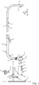
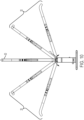
- FIG. 1 shows an exploded perspective view schematic representation of a traction tower 100 according to an embodiment.
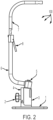
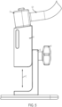
- FIGS. 2 and 3 are assembled perspective view schematic representations of the traction tower 100 shown in FIG. 1 , according to an embodiment.
- the traction tower 100 includes a base plate 1, a tower assembly, and an arm assembly.
- the tower assembly is shown having multiple parts - a lower tower 2 and an upper tower 3 - that fit together, and where the upper tower 3 is moveable with respect to the lower tower 2 (as discussed further below).
- the lower tower 2 is removably securable on the base plate 1 (via any attachment means 15 including a clip, keyed slide and lock mechanism, nut and bolt etc., as should be understood by a person of ordinary skill in the art in conjunction with this disclosure).
- the lower tower 2 can include a peg 2-2, which is biased in the downward (protruding from the bottom surface of the lower tower 2) direction via a spring (not shown) positioned in the lower tower 2.
- the peg 2-2 can be lifted up by sliding button 2-1, and be fully positioned within the lower tower 2.
- the peg 2-2 can fit into a hole formed in the base plate 1 (not shown), and the lower tower can then be turned (clockwise or counterclockwise) to assist with the locking of the lower tower 2 to the base plate 1.
- all other elements/parts of the traction tower 100 can be, but do not have to be, moveable with respect to at least one other element/part of the traction tower 100.
- lower tower 2 is L-shaped and is configured to snuggly fit upper tower 3 as shown.
- the tower assembly can include additional pieces, and can include multiple shapes as long as the pieces fit together in a snug arrangement and the overall movement and locking functionality is similar or remains the same as described herein.
- the tower assembly components here the lower tower 2 and upper tower 3
- the stem 4-1 of locking knob 4 is positionable through lateral apertures positioned in each of lower tower 2 and upper tower 3, and the knob end can be turned to secure each tower component together (as should be understood by a person of skill in the art in conjunction with a review of this disclosure).
- the aperture in the upper tower 3 is a hole (not shown) shaped to snugly fit, engage and secure the stem of the locking knob 4 when the knob end is turned in the appropriate direction (and be disengaged and be released from the aperture in the upper tower when the knob is turned in the opposite direction).
- the aperture 2-3 in lower tower 2 is elongated up and down (partially shown in FIG. 9 ) to allow for upward and downward movement of the upper tower 3 with respect to the lower tower 2, where the upper tower 3 can be resecured to the lower tower 2 per use of the locking knob 4 (as described herein and as should be understood by a person of ordinary skill in the art in conjunction with a review of this disclosure).
- the lower tower 2 can include a different or additional elongated aperture(s) to allow for relative movement of the upper tower 3 with respect to the lower tower 2 in a diagonal direction, horizontal direction, or other directions at an angle to the vertical direction B---B when assembled.
- the types of apertures could be reversed between the upper 3 and lower 2 towers.
- Upper tower 3 also can include an aperture or through hole 14 (longitudinally shaped or other shapes) that can accommodate a strap to hold a patient's forearm to the traction tower 100.
- the upper tower 3 also includes an alignment peg 3-3, which is configured to fit into a corresponding elongated hole (up and down, not shown) in the lower tower 2.
- This alignment peg 3-3 acts in conjunction with the stem 4-1 to assist with the alignment of the upper tower 3 with respect to the lower tower 2 and to prevent the upper tower 3 from unwanted movement/rotation with respect to the lower tower 2 when the relative height of the upper tower 3 is adjusted with respect to the lower tower 2.
- a rotation joint 5 connects the tower assembly to the arm assembly.
- a stem 13 of the rotation joint 5 is positionable and rotatable in the upper tower 3 (as shown, positioned through the top surface 3-1 of the upper tower 3, and as discussed further below).
- the top surface 3-1 of the upper tower is configured to extend along a plane at an angle to the bottom surface 3-2 and/or to the plane of the base plate 1 A---A when assembled.
- the top surface 3-1 can extend along a plane that is parallel to the plane of the base plate 1 A---A.
- the first end of the lower arm 6 includes a slotted base end 12, which is removably positionable, rotatable and lockable within the head 5-1 of the rotation joint 5 (as discussed further below).
- Lower arm 6 extends away from the slotted base end 12 and an elongated lower end 6-1 to a curved portion 11 of the lower arm 6, which extends to an elongated upper end 6-2 of the lower arm 6.
- Upper end 6-2 of the lower arm 6 extends at an angle to an axis (which can be any angle including 45 degrees, substantially perpendicular to perpendicular) of the elongated lower end 6-1.
- An elongated lower end 7-1 of the upper arm 7, can but does not have to be solid, fits and is telescopically moveable within the elongated upper end 6-2 of the lower arm 6, which is formed as a tube.
- Lever 8 is connected to elongated upper end 6-2 of the lower arm 6.
- Lever 8 includes a protrusion or tooth on the end positioned within the elongated upper end 6-2 of the lower arm 6, which can be positioned and fit in between the ridges 7-4 formed on at least one side of the elongated lower end 7-1 of the upper arm 7 (which faces the protrusion or tooth of lever 8 when the elongated lower end 7-1 of the upper arm 7 is positioned within the elongated upper end 6-2 of the lower arm 6).
- lever 8 When lever 8 is actuated in a first direction positioning the protrusion or tooth in between one of the pairs of ridges 7-4, the upper arm 7 is fixed/secured/locked with respect to the lower arm 6.
- lever 8 When lever 8 is actuated in a second direction, the upper arm 7 is released from its fixed/secured/locked position and is free to move with respect to the lower arm 6 (e.g., further within or without the lower arm 6).
- upper arm 7 can be tubular in structure, and lower arm 6 can be solid/non-tubular (but does not have to be) and contain ridges (essentially the opposite configuration shown in FIG. 1 ).
- the lever arm 8 can be any type of actuator including a linear slider, circular actuator or switch etc. (as should be understood by a person of ordinary skill in the art in conjunction with a review of this disclosure).
- Elongated lower end 7-1 of the upper arm 7 extends away from the lower arm to a curved portion 7-2 of the upper arm 7, which extends to an elongated upper end 7-3 of the upper arm 7.
- Upper end 7-3 of the upper arm 7 extends at an angle to an axis (which can be any angle including 45 degrees, substantially perpendicular to perpendicular) of the elongated lower end 7-1, and in essentially the same direction as the elongated lower end 6-1 of the lower arm 6 (and can extend, but does not have to, in a plane that is parallel or substantially parallel thereto; as shown, the elongated lower end 6-1 of the lower arm 6 points slightly more in the relatively downward direction as compared to elongated upper end 7-3 of the upper arm 7, which is shown extending in a plane that is parallel or substantially parallel to plane A---A).
- Elongated upper end 7-3 of the upper arm 7 includes a through hole 7-5 configured to assist with securing a traction tower scale (embodiments of the
- the traction tower 100 As discussed above, there are several structural features and configurations that allow the traction tower 100 as a whole to be sized appropriately for an individual patient.
- the forearm strap position 14 will move with it and is always relatively close to the patient's wrist (the closer to the wrist the better control the strap has). If the strap was in one fixed position it wouldn't work great for different patient sizes.
- FIGS. 4-5 close up perspective view schematic representations of a lower portion of the traction tower 100 shown in FIG. 1 are provided, according to an embodiment.
- FIGS. 4-5 are provided to show movement of upper tower 3 with respect to lower tower 2 to accommodate a variety of individual patent forearm sizes, and the structural features that allow for such movement.
- FIG. 4 shows the upper tower 3 in its relatively lowest position with respect to lower tower 2
- FIG. 5 shows the upper tower 3 in its relatively highest position with respect to the lower tower 2.
- the upper tower 3 is shown fitting snuggly within the outline of the lower tower 2 in the upper tower's 3 lowest position. As shown, the upper tower 3 and the lower tower 2 are held together by the locking knob 4 (as discussed above).
- An interlockable wave/serration pattern 16 may also be provided on each respective lateral facing surface of the upper tower 3 and lower tower 2 to assist with the locking of the upper tower 3 and the lower tower 2 together.
- the wave/serration pattern 16 can cover the whole of each respective lateral facing surface of the upper tower 3 and lower tower 2, or some portion less than the whole of each respective surface.
- adjustment of the upper tower 3 upwards is accomplished by (1) loosening the locking knob 4 and connection between the upper tower 3 and lower tower 2, (2) movement of the knob 4 within the elongated aperture 2-1 (not shown) and upper tower 3 up from the position shown in FIG. 4 to the position shown in FIG. 5 and then tightening the locking knob 4 and upper tower 3 in the new position, and (3) as a result of the movement of the upper tower 3 in the up direction along arrow C, a number of other elements move in the up direction with respect to the lower tower 2 including the strap for the patient's arm (not shown) positionable through aperture 14, rotation joint 5, and the arm assembly.
- the same actions can be performed (i.e., starting with loosening of the locking knob 4, movement of the locking knob 4 and the upper tower 3 etc. in the opposite direction etc.).
- the top surface 3-1 of the upper tower is configured to extend along a plane postitioned at an angle to the plane of the base plate 1 A---A when assembled (see FIG. 1 ).
- the rotation joint 5, being attached to the top portion of the upper tower 3, includes a rotation axis A1 extending at an angle to a straight up and down vertical axis - see B---B of FIG. 1 .
- the rotation joint 5 which houses a portion of the lower arm 6, positioned at an angle with an angled rotation axis A1 (see, e.g., FIG.
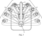
- FIGS. 7 and 8 top and perspective view schematic representations showing the rotation range of rotation joint 5 (and, thus, the arm assembly) of the traction tower 100 about rotation axis A1.
- the rotation D of the rotation joint 5/arm assembly about the rotation axis A1 can be incremental and locked/unlocked via a slotted/tooth embodiment, as shown and described with respect to an additional rotation functionality (see also discussion with respect to FIGS. 18D-E ), can be non-incremental when locked/unlocked via frictional engagement, or can be locked/unlocked via other known lock/unlock mechanisms (as should be understood by a person of ordinary skill in the art in conjunction with a review of this disclosure).
- the rotation range is shown by shadow (transparent) arm assembly structures 20 positioned around the starting or zero position shown by a solid arm assembly structure 30.
- the position of the screw (not shown) that holds the traction scale at 7-5 remains consistent despite the rotation of the other portions of the arm assembly.
- a large portion of the arm assembly is offset from a patient's arm when in use, regardless of the arm assembly's rotation position, which creates sufficient space for surgical instruments.
- this structural configuration and associated functionality allows a medical practitioner to move the arm assembly around the patient's hand without affecting the position or traction of the hand itself.
- the ability to rotate the arm assembly can be important because if the medical practitioner needs more space around the outside of the wrist joint for medical instruments, the medical practitioner can just swing the arm assembly around to the back of the arm.
- Another use of this structural feature includes allowing the medical practitioner to maneuver the arm assembly in order to get a c-arm (x-ray machine) into position to take an x-ray while the wrist remains in traction.
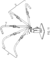
- FIG. 9 a close up partially sectioned perspective view of a lower portion of the traction tower 100 is shown, according to an embodiment.
- the interface between the slotted base end 12 of the elongated lower end 6-1 of the lower arm 6 and the rotation joint 5 is shown.
- the slots/teeth formed on the slotted base end 12 allow for incremental rotation of the arm assembly around a second rotation axis E---E as shown in FIGS. 10 and 11 .
- a main purpose of the rotation of the elongated lower end 6-1 of the lower arm 6 around the second rotation axis E---E is to allow the medical practitioner to control the angle of the patient's wrist while in use by keeping the patient's forearm vertical and pulling traction to the hand at an angle from an elongated axis positioned through the patient's forearm (or vertically), as should be understood by a person of ordinary skill in the art in conjunction with a review of this disclosure.
- this forearm strap 300 shown in FIGs. 29A-29B connects to the upper tower component 3 of the traction tower 100. Since the upper tower 3 of the traction tower 100 can be positioned higher or lower based upon the patient's anatomy, the forearm strap 300 will always be positioned close to the patient's wrist. The closer the strap 300 is to the side forces being applied by the surgeon during the procedure, the more effective it will be at preventing side to side movement of the wrist.
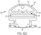
- FIGs 30A-30C there are shown front, side, and back views schematic representations of the buckle 306, according to an embodiment.
- the buckles 306 shown in FIGs 30A-30C are easily adjustable and have high locking strength.
- the buckle 306 has a rounded profile.
- the top surface 314 ( FIG. 30A ) and the bottom surface 316 ( FIG. 30C ) of the buckle 306 are curved such that the buckle 306 lays comfortably against the patient's arm and adapts well to arms of different sizes.
- the buckle 306 has a rounded top portion 318 connected to a rectangular adjustability section 320.
- the adjustability section 320 is connected to a substantially rectangular base portion 322 with one or more connectors 323 extending therefrom.
- the side view of the buckle 306 shows that the side profile of the buckle 306 is rounded from the top portion 318 to the base portion 322.
- the bottom surface 316 of the buckle 306 has a ridge 324 extending around the perimeter of the top portion 318.
- the ridge 324 is designed to function as an ergonomic thumb ridge to allow for an increased grip on the buckle 306 by the user for ease in releasing the strap 300 around the patient's arm. The increased grip is especially beneficial when the user is manipulating the strap 300 with wet gloves.
- the bottom surface 316 of the buckle 306 has one or more flanges 326 extending from the base portion 322.
- the flanges 326 are triangular, as shown in the side profile of the buckle 306 in FIG. 30B .
- the flanges 326 guide the buckle 306 when the user slides the buckle 306 into the base plate 1 of the traction tower 100.
- the flanges 326 add rigidity to the base portion 322 where the buckle 306 experiences most of the force.
- the overall profile of the buckle 306 is thin. This allows the buckle 306 to encompass the bottom of the bicep as well.
- the buckle 306 has an interference angle extending along an outer edge 330 of the prong 332 extending across the adjustability section 320.
- the interference angle in the buckle 306 of FIG. 30B is steep, within the range of 0 - 45 degrees. The steep interference angle provides high friction between the length of material 302 while in use and an easy release when the first or second end 308, 310 of the length of material 302 is pulled down away from the patient's arm.
- the slot 342 extends along an axis that is perpendicular to axes extending through each column 338.
- the slot 342 is asymmetrical to only allow the correct insertion orientation while preventing incorrect insertion orientation.
- the forearm buckle mount 334 encourages free, low friction rotation of the length of material 302.
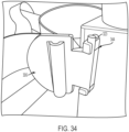
- the forearm buckle mount 334 includes a buckle interface 344 for rotatably attaching to the connectors 323 of the buckle 306.
- the buckle 306 and the forearm buckle mount 334 are shown attached to the traction tower 100.
- the outer flange 340 of the forearm buckle mount 334 extends from a first side 430 of the traction tower 100 and the buckle interface 344 of the forearm buckle mount 334 extends from an opposing second side 432 of the traction tower 100.
- the buckle 306 is rotatable about the buckle interface 344 of the forearm buckle mount 334 relative to the second side 432 of the traction tower 100.
- the buckle interface 344 has an audible snap and haptic feedback to indicate that the connectors 323 of the buckle 306 have been attached to the forearm buckle mount 334.
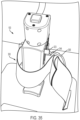
- FIG. 35 shows the traction tower 100 with the strap 300 attached.
- the buckle 306 stays in place within the buckle interface 344 while in use and easily snaps out when the user is done using the buckle 306.
- the same buckles 306 are used as the bicep strap 300 with full rotation availability.
- the finger trap 400 has a length of flexible material 402 with a first end 404 and a second end 406.
- the length of flexible material 402 is composed of mesh or braided material.
- the length of flexible material 402 can be a double-layered mesh material.
- the length of flexible material 402 is closed at the first end 404 and open at the second end 406.
- the length of flexible material 402 is tapered or funneled with a reduced diameter at the first end 404 and an increasing diameter toward the second end 406.
- the length of flexible material 402 is tubular and rounded with an inner volume 408 for ease of finger insertion.
- the length of flexible material 402 is approximately six inches in length to accommodate various sizes of fingers.
- a fastener 410 is attached at or near the second end 406 of the finger trap 400.
- the fastener 410 is a hook and loop fastener 410.
- the fastener 410 is woven through the length of flexible material 402 at at least one location. Specifically, as shown in FIG. 36 , the fastener 410 extends through the length of flexible material 402 into the inner volume 408 and back out through the length of flexible material 402.
- the fastener 410 is used to adjust the diameter of the inner volume 408 of the length of flexible material 402 at or near the second end 406. This allows for the quick and easy adjustment of the finger trap 400. With the fastener 410 locked, the fastener 410 resists shear forces from the finger of the patient being pulled out.
- the finger trap 400 includes a tension mechanism 412 extending therefrom.
- the tension mechanism to increase or decrease tension on the finger trap 400.
- the tension mechanism 412 is a crimp ball chain.
- the crimp ball chain comprises a collar 414 extending around the length of flexible material 402 at or near the first end 404.
- the collar 414 has a ball chain 416 extending therefrom.
- the ball chain 416 is a chain composed of a series of spaced beads 418.
- the ball chain 416 terminates in a hook 420 for attachment to the traction tower 100.
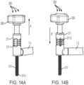
- the traction tower 100 tensions to the hook 420 and the user can increase and decrease tension by replacing the ball chain 416 in the rack 203 at the desired tension.
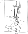
- FIG. 37 there is shown a perspective view photographic representation of a finger trap 400 attached to the traction tower 100, according to an embodiment.
- the finger trap 400 feature a releasable cable tie 422 which allows the surgeon to tighten and loosen the finger trap 400 on patients finger.
- the finger trap 400 incorporated the adjustable cable tie 422 to make these finger trap a one-size fits all.
- the cable tie 422 can be tightened to initiate the length of flexible material 402 holding the finger.
- the cable tie 422 can be released (non-destructively) if the finger trap 400 needs to be removed and placed onto another finger or the thumb.
- a finger trap that functions on the patient's index finger or ring finger is not likely to work on the thumb or pinky finger. This could lead to scenarios wherein surgeons will have to use oversized finger traps to ensure they at least fit on all the fingers of the patient. This requires that the surgeons compensate for the large size by taping over of the finger traps on the smaller fingers to try to secure them. Additionally, the surgeon has to adjust the traction settings from the traction tower 100 more frequently because the finger traps would slip (due to oversize), resulting in a loss of traction.
- adjustable cable ties 422 never directly contact the patient's fingers.
- the cable ties 422 only pierce through a single layer of the length of flexible material 402 (e.g., doubled over braided hose). This ensures that the length of flexible material 402 engages with the entire circumference of the finger so that when traction is applied, the length of flexible material 402 performs the function of dispersing the traction force over the entire finger instead of just where the cable tie 422 is tightened.
- Approximating language may be applied to modify any quantitative representation that could permissibly vary without resulting in a change in the basic function to which it is related. Accordingly, a value modified by a term or terms, such as “about” and “substantially”, are not to be limited to the precise value specified. In at least some instances, the approximating language may correspond to the precision of an instrument for measuring the value.
- range limitations may be combined and/or interchanged; such ranges are identified and include all the sub-ranges contained therein unless context or language indicates otherwise.
Landscapes
- Health & Medical Sciences (AREA)
- Life Sciences & Earth Sciences (AREA)
- Animal Behavior & Ethology (AREA)
- General Health & Medical Sciences (AREA)
- Public Health (AREA)
- Veterinary Medicine (AREA)
- Engineering & Computer Science (AREA)
- Biomedical Technology (AREA)
- Heart & Thoracic Surgery (AREA)
- Orthopedic Medicine & Surgery (AREA)
- Nursing (AREA)
- Vascular Medicine (AREA)
- Surgery (AREA)
- Nuclear Medicine, Radiotherapy & Molecular Imaging (AREA)
- Molecular Biology (AREA)
- Medical Informatics (AREA)
- Epidemiology (AREA)
- Rehabilitation Therapy (AREA)
- Pain & Pain Management (AREA)
- Physical Education & Sports Medicine (AREA)
- Orthopedics, Nursing, And Contraception (AREA)
- Surgical Instruments (AREA)
- Other Liquid Machine Or Engine Such As Wave Power Use (AREA)
- Ladders (AREA)
- Accommodation For Nursing Or Treatment Tables (AREA)
Applications Claiming Priority (4)
| Application Number | Priority Date | Filing Date | Title |
|---|---|---|---|
| US201962871146P | 2019-07-07 | 2019-07-07 | |
| US201962930115P | 2019-11-04 | 2019-11-04 | |
| PCT/US2020/036376 WO2021006971A1 (en) | 2019-07-07 | 2020-06-05 | Traction tower trap and finger trap system |
| EP20750408.5A EP3993742B1 (de) | 2019-07-07 | 2020-06-05 | Traktionsturmfang und fingerfangsystem |
Related Parent Applications (2)
| Application Number | Title | Priority Date | Filing Date |
|---|---|---|---|
| EP20750408.5A Division EP3993742B1 (de) | 2019-07-07 | 2020-06-05 | Traktionsturmfang und fingerfangsystem |
| EP20750408.5A Division-Into EP3993742B1 (de) | 2019-07-07 | 2020-06-05 | Traktionsturmfang und fingerfangsystem |
Publications (3)
| Publication Number | Publication Date |
|---|---|
| EP4529900A2 true EP4529900A2 (de) | 2025-04-02 |
| EP4529900A3 EP4529900A3 (de) | 2025-06-11 |
| EP4529900B1 EP4529900B1 (de) | 2026-04-22 |
Family
ID=71899833
Family Applications (3)
| Application Number | Title | Priority Date | Filing Date |
|---|---|---|---|
| EP25152464.1A Pending EP4529901A3 (de) | 2019-07-07 | 2020-06-05 | Zugturmfalle und fingerfallensystem |
| EP20750408.5A Active EP3993742B1 (de) | 2019-07-07 | 2020-06-05 | Traktionsturmfang und fingerfangsystem |
| EP25152461.7A Active EP4529900B1 (de) | 2019-07-07 | 2020-06-05 | Zugturmfalle und fingerfallensystem |
Family Applications Before (2)
| Application Number | Title | Priority Date | Filing Date |
|---|---|---|---|
| EP25152464.1A Pending EP4529901A3 (de) | 2019-07-07 | 2020-06-05 | Zugturmfalle und fingerfallensystem |
| EP20750408.5A Active EP3993742B1 (de) | 2019-07-07 | 2020-06-05 | Traktionsturmfang und fingerfangsystem |
Country Status (9)
| Country | Link |
|---|---|
| US (1) | US20220354683A1 (de) |
| EP (3) | EP4529901A3 (de) |
| JP (3) | JP7330355B2 (de) |
| KR (2) | KR20240154708A (de) |
| CN (2) | CN120022043A (de) |
| AU (3) | AU2020311286B2 (de) |
| CA (3) | CA3224653A1 (de) |
| ES (1) | ES3018139T3 (de) |
| WO (1) | WO2021006971A1 (de) |
Families Citing this family (1)
| Publication number | Priority date | Publication date | Assignee | Title |
|---|---|---|---|---|
| US11771581B1 (en) * | 2022-08-23 | 2023-10-03 | Traktus Llc | Surgical jig and method for using same |
Family Cites Families (35)
| Publication number | Priority date | Publication date | Assignee | Title |
|---|---|---|---|---|
| US3850166A (en) * | 1973-03-30 | 1974-11-26 | S Tamny | Fracture reduction system |
| US3872861A (en) * | 1973-08-20 | 1975-03-25 | Simon Tamny | Contractable finger trap |
| US4005506A (en) * | 1975-06-09 | 1977-02-01 | Moore Robert R | Adjustable strap assembly |
| SE445291B (sv) * | 1981-05-13 | 1986-06-16 | Landstingens Inkopscentral | Repositionsapparat |
| US4655206A (en) * | 1984-03-02 | 1987-04-07 | Brian Moody | Spinal restraint |
| US5113876A (en) * | 1990-04-26 | 1992-05-19 | Herman John A | Skeletal stabilization apparatus for use in transporting and treating patients and methods therefor |
| US5074291A (en) * | 1990-09-17 | 1991-12-24 | Carter Peter R | Hand traction surgical table |
| US5451203A (en) * | 1994-07-29 | 1995-09-19 | Orthopedic Systems, Inc. | Traction mechanism |
| US5632726A (en) * | 1995-11-06 | 1997-05-27 | Repice; Ronald M. | Device for use on a traction machine to treat carpal tunnel syndrome and other problems of the wrist |
| US5868691A (en) * | 1996-10-15 | 1999-02-09 | Vishnevsky; John | Posture training device |
| US5702355A (en) | 1997-01-14 | 1997-12-30 | Ronald M. Repice | Portable adjustable traction appliance to treat carpal tunnel syndrome and other problems of the wrist |
| US6092525A (en) * | 1997-01-27 | 2000-07-25 | Church; Steve | Spinal immobilization device |
| US6533741B1 (en) * | 2000-01-06 | 2003-03-18 | Roger W. Lee | Articulated upper extremity splint to immobilize and support an injured limb |
| US6435188B2 (en) * | 2000-07-10 | 2002-08-20 | Martin G. Tyrrell | Patient immobilization system |
| US6517506B1 (en) * | 2001-04-11 | 2003-02-11 | Burl Pettibon | Cervical traction device and method |
| US6796953B2 (en) * | 2002-12-12 | 2004-09-28 | Efren B. Aduana, Jr. | Cervical traction device |
| US7131955B2 (en) * | 2004-03-05 | 2006-11-07 | Price Geoffrey M | Orthopedic traction tower system |
| US20060161086A1 (en) * | 2005-01-18 | 2006-07-20 | Dennis Lambert | Traction device |
| CN2912669Y (zh) * | 2006-03-06 | 2007-06-20 | 邵鲁克 | 输液固定器 |
| US8545373B2 (en) | 2007-07-12 | 2013-10-01 | Peter Scott Borden | Shoulder stretcher and method of use |
| CN201248813Y (zh) * | 2008-09-13 | 2009-06-03 | 张淑爱 | 精神病人专用床 |
| US8356601B2 (en) * | 2009-08-31 | 2013-01-22 | Hunter Jr Alton Lee | Arm stabilizer device and methods |
| WO2011112658A1 (en) * | 2010-03-09 | 2011-09-15 | Innovision, Inc. | Limb positioner |
| JP4714796B1 (ja) * | 2010-08-20 | 2011-06-29 | 紳一 中光 | 携帯型もしくは身体装着型の骨折治療装置 |
| US8839797B1 (en) * | 2012-12-26 | 2014-09-23 | Imp Inc. | Method and apparatus for securing a patient's hand during arthroscopy and surgery |
| US9814646B2 (en) | 2013-07-10 | 2017-11-14 | Delolmo Holdings, LLC | System for securely positioning a cervical spine during surgery |
| CN203915158U (zh) * | 2014-04-25 | 2014-11-05 | 苏州中骨医疗科技发展有限公司 | 单边式膝关节矫形器 |
| CN205286591U (zh) * | 2015-12-25 | 2016-06-08 | 南阳医学高等专科学校 | 一种动物实验用固定支架 |
| CN107028628A (zh) * | 2016-02-03 | 2017-08-11 | 北京积水潭医院 | 一种医用腕关节镜手术多体位牵引架 |
| CN105997163A (zh) * | 2016-05-13 | 2016-10-12 | 上海凯利泰医疗科技股份有限公司 | 一种腕关节和指关节手术牵引固定装置 |
| EP3474696B1 (de) * | 2016-06-23 | 2020-11-18 | Darco International Inc. | Medizinischer schuh mit mehreren aussensohlenprojektionen |
| CN206080815U (zh) * | 2016-07-12 | 2017-04-12 | 段亚景 | 一种可调式下肢固定装置 |
| CN208274663U (zh) * | 2017-11-24 | 2018-12-25 | 宋涛 | 一种轻便型骨折复位器 |
| CN208130227U (zh) * | 2017-12-14 | 2018-11-23 | 成都名典匠心工业产品设计有限公司 | 一种精神科输液用固定板 |
| CN108309672B (zh) * | 2018-02-23 | 2022-06-07 | 南京市第一医院 | 一种腕关节手术牵引支架 |
-
2020
- 2020-06-05 CA CA3224653A patent/CA3224653A1/en active Pending
- 2020-06-05 CN CN202510162237.8A patent/CN120022043A/zh active Pending
- 2020-06-05 EP EP25152464.1A patent/EP4529901A3/de active Pending
- 2020-06-05 CA CA3278497A patent/CA3278497A1/en active Pending
- 2020-06-05 JP JP2022500506A patent/JP7330355B2/ja active Active
- 2020-06-05 CA CA3143591A patent/CA3143591C/en active Active
- 2020-06-05 KR KR1020247034933A patent/KR20240154708A/ko active Pending
- 2020-06-05 EP EP20750408.5A patent/EP3993742B1/de active Active
- 2020-06-05 US US17/622,420 patent/US20220354683A1/en active Pending
- 2020-06-05 WO PCT/US2020/036376 patent/WO2021006971A1/en not_active Ceased
- 2020-06-05 CN CN202080049298.9A patent/CN114096218A/zh active Pending
- 2020-06-05 EP EP25152461.7A patent/EP4529900B1/de active Active
- 2020-06-05 KR KR1020227002178A patent/KR102721245B1/ko active Active
- 2020-06-05 AU AU2020311286A patent/AU2020311286B2/en active Active
- 2020-06-05 ES ES20750408T patent/ES3018139T3/es active Active
-
2023
- 2023-04-17 AU AU2023202345A patent/AU2023202345B2/en active Active
- 2023-08-08 JP JP2023128993A patent/JP7639076B2/ja active Active
-
2024
- 2024-10-31 JP JP2024191396A patent/JP2025016640A/ja active Pending
-
2025
- 2025-06-30 AU AU2025204932A patent/AU2025204932A1/en active Pending
Also Published As
| Publication number | Publication date |
|---|---|
| CA3143591A1 (en) | 2021-01-14 |
| KR20240154708A (ko) | 2024-10-25 |
| JP2025016640A (ja) | 2025-02-04 |
| JP2022539594A (ja) | 2022-09-12 |
| AU2025204932A1 (en) | 2025-07-17 |
| JP7639076B2 (ja) | 2025-03-04 |
| CN120022043A (zh) | 2025-05-23 |
| AU2020311286B2 (en) | 2023-03-16 |
| AU2020311286A1 (en) | 2022-01-20 |
| ES3018139T3 (en) | 2025-05-14 |
| KR20220043111A (ko) | 2022-04-05 |
| AU2023202345B2 (en) | 2025-04-03 |
| KR102721245B1 (ko) | 2024-10-23 |
| EP4529900B1 (de) | 2026-04-22 |
| JP7330355B2 (ja) | 2023-08-21 |
| CN114096218A (zh) | 2022-02-25 |
| EP4529901A2 (de) | 2025-04-02 |
| EP3993742B1 (de) | 2025-03-05 |
| EP4529900A3 (de) | 2025-06-11 |
| EP3993742A1 (de) | 2022-05-11 |
| WO2021006971A1 (en) | 2021-01-14 |
| CA3224653A1 (en) | 2021-01-14 |
| EP4529901A3 (de) | 2025-06-11 |
| CA3143591C (en) | 2025-10-07 |
| AU2023202345A1 (en) | 2023-05-11 |
| US20220354683A1 (en) | 2022-11-10 |
| CA3278497A1 (en) | 2025-10-31 |
| JP2023159192A (ja) | 2023-10-31 |
Similar Documents
| Publication | Publication Date | Title |
|---|---|---|
| CN105899147B (zh) | 手术用牵开器系统和方法 | |
| AU2023202345B2 (en) | Traction tower trap and finger trap system | |
| US20100293766A1 (en) | Tensioning Apparatus for Strap | |
| AU2020214430B2 (en) | Wrist traction tower and traction tower scale |
Legal Events
| Date | Code | Title | Description |
|---|---|---|---|
| PUAI | Public reference made under article 153(3) epc to a published international application that has entered the european phase |
Free format text: ORIGINAL CODE: 0009012 |
|
| STAA | Information on the status of an ep patent application or granted ep patent |
Free format text: STATUS: REQUEST FOR EXAMINATION WAS MADE |
|
| 17P | Request for examination filed |
Effective date: 20250214 |
|
| AC | Divisional application: reference to earlier application |
Ref document number: 3993742 Country of ref document: EP Kind code of ref document: P |
|
| AK | Designated contracting states |
Kind code of ref document: A2 Designated state(s): AL AT BE BG CH CY CZ DE DK EE ES FI FR GB GR HR HU IE IS IT LI LT LU LV MC MK MT NL NO PL PT RO RS SE SI SK SM TR |
|
| PUAL | Search report despatched |
Free format text: ORIGINAL CODE: 0009013 |
|
| AK | Designated contracting states |
Kind code of ref document: A3 Designated state(s): AL AT BE BG CH CY CZ DE DK EE ES FI FR GB GR HR HU IE IS IT LI LT LU LV MC MK MT NL NO PL PT RO RS SE SI SK SM TR |
|
| RIC1 | Information provided on ipc code assigned before grant |
Ipc: A61F 5/04 20060101AFI20250506BHEP |
|
| REG | Reference to a national code |
Ref country code: DE Ref legal event code: R079 Free format text: PREVIOUS MAIN CLASS: A61F0005040000 Ipc: A61F0005370000 Ref document number: 602020071027 Country of ref document: DE |
|
| GRAP | Despatch of communication of intention to grant a patent |
Free format text: ORIGINAL CODE: EPIDOSNIGR1 |
|
| STAA | Information on the status of an ep patent application or granted ep patent |
Free format text: STATUS: GRANT OF PATENT IS INTENDED |
|
| RIC1 | Information provided on ipc code assigned before grant |
Ipc: A61F 5/37 20060101AFI20260202BHEP Ipc: A61F 5/04 20060101ALI20260202BHEP |
|
| GRAS | Grant fee paid |
Free format text: ORIGINAL CODE: EPIDOSNIGR3 |
|
| INTG | Intention to grant announced |
Effective date: 20260212 |
|
| GRAA | (expected) grant |
Free format text: ORIGINAL CODE: 0009210 |
|
| STAA | Information on the status of an ep patent application or granted ep patent |
Free format text: STATUS: THE PATENT HAS BEEN GRANTED |
|
| AC | Divisional application: reference to earlier application |
Ref document number: 3993742 Country of ref document: EP Kind code of ref document: P |
|
| AK | Designated contracting states |
Kind code of ref document: B1 Designated state(s): AL AT BE BG CH CY CZ DE DK EE ES FI FR GB GR HR HU IE IS IT LI LT LU LV MC MK MT NL NO PL PT RO RS SE SI SK SM TR |
|
| REG | Reference to a national code |
Ref country code: CH Ref legal event code: F10 Free format text: ST27 STATUS EVENT CODE: U-0-0-F10-F00 (AS PROVIDED BY THE NATIONAL OFFICE) Effective date: 20260422 Ref country code: GB Ref legal event code: FG4D |