EP4529348A2 - Benutzergerät und planungsknoten - Google Patents
Benutzergerät und planungsknoten Download PDFInfo
- Publication number
- EP4529348A2 EP4529348A2 EP25155848.2A EP25155848A EP4529348A2 EP 4529348 A2 EP4529348 A2 EP 4529348A2 EP 25155848 A EP25155848 A EP 25155848A EP 4529348 A2 EP4529348 A2 EP 4529348A2
- Authority
- EP
- European Patent Office
- Prior art keywords
- paging
- pdcch
- allocation
- time instance
- paging time
- Prior art date
- Legal status (The legal status is an assumption and is not a legal conclusion. Google has not performed a legal analysis and makes no representation as to the accuracy of the status listed.)
- Pending
Links
Images


Classifications
-
- H—ELECTRICITY
- H04—ELECTRIC COMMUNICATION TECHNIQUE
- H04W—WIRELESS COMMUNICATION NETWORKS
- H04W68/00—User notification, e.g. alerting and paging, for incoming communication, change of service or the like
- H04W68/02—Arrangements for increasing efficiency of notification or paging channel
-
- H—ELECTRICITY
- H04—ELECTRIC COMMUNICATION TECHNIQUE
- H04W—WIRELESS COMMUNICATION NETWORKS
- H04W72/00—Local resource management
- H04W72/20—Control channels or signalling for resource management
- H04W72/23—Control channels or signalling for resource management in the downlink direction of a wireless link, i.e. towards a terminal
-
- H—ELECTRICITY
- H04—ELECTRIC COMMUNICATION TECHNIQUE
- H04W—WIRELESS COMMUNICATION NETWORKS
- H04W74/00—Wireless channel access
- H04W74/08—Non-scheduled access, e.g. ALOHA
- H04W74/0808—Non-scheduled access, e.g. ALOHA using carrier sensing, e.g. carrier sense multiple access [CSMA]
-
- H—ELECTRICITY
- H04—ELECTRIC COMMUNICATION TECHNIQUE
- H04W—WIRELESS COMMUNICATION NETWORKS
- H04W88/00—Devices specially adapted for wireless communication networks, e.g. terminals, base stations or access point devices
- H04W88/02—Terminal devices
-
- H—ELECTRICITY
- H04—ELECTRIC COMMUNICATION TECHNIQUE
- H04W—WIRELESS COMMUNICATION NETWORKS
- H04W88/00—Devices specially adapted for wireless communication networks, e.g. terminals, base stations or access point devices
- H04W88/08—Access point devices
Definitions
- the present disclosure relates to transmission and reception of signals in a communication system.
- the present disclosure relates to methods and apparatuses for such transmission and reception.
- the 3rd Generation Partnership Project (3GPP) works at technical specifications for the next generation cellular technology, which is also called fifth generation (5G) including "New Radio" (NR) radio access technology (RAT), which operates in frequency ranges up to 100 GHz.
- 5G Fifth Generation
- NR radio access technology
- the NR is a follower of the technology represented by Long Term Evolution (LTE) and LTE Advanced (LTE-A).
- One non-limiting and exemplary embodiment facilitates efficiently utilizing resources including UE power and a channel occupancy time when paging is performed or scheduled in the channel occupancy time.
- the techniques disclosed herein feature a user equipment, UE, comprising a transceiver which, in operation, receives at least one physical downlink control channel, PDCCH from which allocation of a paging time instance to be monitored for paging downlink control information, DCI, is determinable, and circuitry which, in operation, determines the allocation of the paging time instance to be monitored based on the received at least one PDCCH, wherein the transceiver, in operation, performs monitoring for the paging DCI based on the determination of the allocation of the paging time instance.
- PDCCH physical downlink control channel
- DCI downlink control information
- 5G 5 th generation cellular technology
- NR radio access technology
- the first version of the 5G standard was completed at the end of 2017, which allows proceeding to 5G NR standard-compliant trials and commercial deployments of smartphones.
- the overall system architecture assumes an NG-RAN (Next Generation - Radio Access Network) that comprises gNBs, providing the NG-radio access user plane (SDAP/PDCP/RLC/MAC/PHY) and control plane (RRC) protocol terminations towards the UE.
- the gNBs are interconnected with each other by means of the Xn interface.
- the gNBs are also connected by means of the Next Generation (NG) interface to the NGC (Next Generation Core), more specifically to the AMF (Access and Mobility Management Function) (e.g. a particular core entity performing the AMF) by means of the NG-C interface and to the UPF (User Plane Function) (e.g. a particular core entity performing the UPF) by means of the NG-U interface.
- the NG-RAN architecture is illustrated in Fig. 1 (see e.g. 3GPP TS 38.300 v15.6.0, section 4).
- a non-centralized deployment scenario (see e.g. section 5.2 of TR 38.801; a centralized deployment is illustrated in section 5.4) is presented therein, where base stations supporting the 5G NR can be deployed.
- Fig. 2 illustrates an exemplary non-centralized deployment scenario (see e.g. Figure 5.2.-1 of said TR 38.801), while additionally illustrating an LTE eNB as well as a user equipment (UE) that is connected to both a gNB and an LTE eNB.
- the new eNB for NR 5G may be exemplarily called gNB.
- An eLTE eNB is the evolution of an eNB that supports connectivity to the EPC (Evolved Packet Core) and the NGC (Next Generation Core).
- EPC Evolved Packet Core
- NGC Next Generation Core
- the user plane protocol stack for NR (see e.g. 3GPP TS 38.300, section 4.4.1) comprises the PDCP (Packet Data Convergence Protocol, see section 6.4 of TS 38.300), RLC (Radio Link Control, see section 6.3 of TS 38.300) and MAC (Medium Access Control, see section 6.2 of TS 38.300) sublayers, which are terminated in the gNB on the network side. Additionally, a new access stratum (AS) sublayer (SDAP, Service Data Adaptation Protocol) is introduced above PDCP (see e.g. sub-clause 6.5 of 3GPP TS 38.300).
- a control plane protocol stack is also defined for NR (see for instance TS 38.300, section 4.4.2).
- the Medium-Access-Control layer handles logical-channel multiplexing, and scheduling and scheduling-related functions, including handling of different numerologies.
- the physical layer is for example responsible for coding, PHY HARQ processing, modulation, multi-antenna processing, and mapping of the signal to the appropriate physical time-frequency resources. It also handles mapping of transport channels to physical channels.
- the physical layer provides services to the MAC layer in the form of transport channels.
- a physical channel corresponds to the set of time-frequency resources used for transmission of a particular transport channel, and each transport channel is mapped to a corresponding physical channel.
- One physical channel is the PRACH (Physical Random Access Channel) used for the random access.
- Use cases / deployment scenarios for NR could include enhanced mobile broadband (eMBB), ultra-reliable low-latency communications (URLLC), massive machine type communication (mMTC), which have diverse requirements in terms of data rates, latency, and coverage.
- eMBB enhanced mobile broadband
- URLLC ultra-reliable low-latency communications
- mMTC massive machine type communication
- eMBB is expected to support peak data rates (20Gbps for downlink and 10Gbps for uplink) and user-experienced data rates in the order of three times what is offered by IMT-Advanced.
- URLLC the tighter requirements are put on ultra-low latency (0.5ms for UL and DL each for user plane latency) and high reliability (1-10 -5 within 1ms).
- mMTC may preferably require high connection density (1,000,000 devices/km 2 in an urban environment), large coverage in harsh environments, and extremely long-life battery for low cost devices (15 years).
- the OFDM numerology e.g. subcarrier spacing, OFDM symbol duration, cyclic prefix (CP) duration, number of symbols per scheduling interval
- the OFDM numerology e.g. subcarrier spacing, OFDM symbol duration, cyclic prefix (CP) duration, number of symbols per scheduling interval
- low-latency services may preferably require a shorter symbol duration (and thus larger subcarrier spacing) and/or fewer symbols per scheduling interval (aka, TTI) than an mMTC service.
- deployment scenarios with large channel delay spreads may preferably require a longer CP duration than scenarios with short delay spreads.
- the subcarrier spacing should be optimized accordingly to retain the similar CP overhead.
- NR may support more than one value of subcarrier spacing.
- subcarrier spacing of 15kHz, 30kHz, 60 kHz... are being considered at the moment.
- the term "resource element" can be used to denote a minimum resource unit being composed of one subcarrier for the length of one OFDM/SC-FDMA symbol.
- a resource grid of subcarriers and OFDM symbols is defined respectively for uplink and downlink.
- Each element in the resource grid is called a resource element and is identified based on the frequency index in the frequency domain and the symbol position in the time domain (see 3GPP TS 38.211 v15.6.0).
- 5G NR functional split between NG-RAN and 5GC
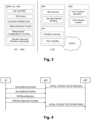
- Fig. 3 illustrates functional split between NG-RAN and 5GC.
- NG-RAN logical node is a gNB or ng-eNB.
- the 5GC has logical nodes AMF, UPF and SMF.
- the gNB and ng-eNB host the following main functions:
- UPF User Plane Function
- Session Management function hosts the following main functions:
- an entity for example AMF, SMF, etc.
- a 5th Generation Core 5GC
- comprises control circuitry which, in operation, establishes a Next Generation (NG) connection with a gNodeB (or gNB), and a transmitter which, in operation, transmits an initial context setup message, via the NG connection, to the gNodeB to cause a signaling radio bearer setup between the gNodeB and a user equipment (UE).
- the gNodeB transmits a Radio Resource Control, RRC, signaling containing a resource allocation configuration information element to the UE via the signaling radio bearer.
- RRC Radio Resource Control
- the UE then performs an uplink transmission or a downlink reception based on the resource allocation configuration.
- the URLLC use case has stringent requirements for capabilities such as throughput, latency and availability and has been envisioned as one of the enablers for future vertical applications such as wireless control of industrial manufacturing or production processes, remote medical surgery, distribution automation in a smart grid, transportation safety, etc.
- Ultra-reliability for URLLC is to be supported by identifying the techniques to meet the requirements set by TR 38.913.
- key requirements include a target user plane latency of 0.5 ms for UL (uplink) and 0.5 ms for DL (downlink).
- the general URLLC requirement for one transmission of a packet is a BLER (block error rate) of 1E-5 for a packet size of 32 bytes with a user plane latency of 1ms.
- NR URLCC Augmented Reality/Virtual Reality (AR/VR), e-health, e-safety, and mission-critical applications.
- AR/VR Augmented Reality/Virtual Reality
- technology enhancements targeted by NR URLCC aim at latency improvement and reliability improvement.
- Technology enhancements for latency improvement include configurable numerology, non slot-based scheduling with flexible mapping, grant free (configured grant) uplink, slot-level repetition for data channels, and downlink pre-emption.
- Pre-emption means that a transmission for which resources have already been allocated is stopped, and the already allocated resources are used for another transmission that has been requested later, but has lower latency / higher priority requirements. Accordingly, the already granted transmission is pre-empted by a later transmission.
- Pre-emption is applicable independent of the particular service type. For example, a transmission for a service-type A (URLCC) may be pre-empted by a transmission for a service type B (such as eMBB).
- Technology enhancements with respect to reliability improvement include dedicated CQI/MCS tables for the target BLER of 1E-5.
- a slot corresponds to the timing granularity (TTI - transmission time interval) for scheduling assignment.
- TTI determines the timing granularity for scheduling assignment.
- One TTI is the time interval in which given signals is mapped to the physical layer.
- the TTI length can vary from 14-symbols (slot-based scheduling) to 2-symbols (non-slot based scheduling).
- Downlink (DL) and uplink (UL) transmissions are specified to be organized into frames (10 ms duration) consisting of 10 subframes (1 ms duration).
- a subframe is further divided into slots, the number of slots being defined by the numerology / subcarrier spacing.
- the specified values range between 10 slots per frame (1 slot per subframe) for a subcarrier spacing of 15 kHz to 80 slots per frame (8 slots per subframe) for a subcarrier spacing of 120 kHz.
- the number of OFDM symbols per slot is 14 for normal cyclic prefix and 12 for extended cyclic prefix (see section 4.1 (general frame structure), 4.2 (Numerologies), 4.3.1 (frames and subframes) and 4.3.2 (slots) of the 3GPP TS 38.211 V15.3.0, Physical channels and modulation, 2018-09).
- assignment of time resources for transmission may also be non-slot based.
- the TTls in non slot-based assignment may correspond to mini-slots rather than slots. I.e., one or more mini-slots may be assign to a requested transmission of data/control signaling.
- the minimum length of a TTI may for instance be 1 or 2 OFDM symbols.
- the 5G QoS (Quality of Service) model is based on QoS flows and supports both QoS flows that require guaranteed flow bit rate (GBR QoS flows) and QoS flows that do not require guaranteed flow bit rate (non-GBR QoS Flows).
- GRR QoS flows QoS flows that require guaranteed flow bit rate
- non-GBR QoS Flows QoS flows that do not require guaranteed flow bit rate
- the QoS flow is thus the finest granularity of QoS differentiation in a PDU session.
- a QoS flow is identified within a PDU session by a QoS flow ID (QFI) carried in an encapsulation header over NG-U interface.
- QFI QoS flow ID
- 5GC For each UE, 5GC establishes one or more PDU Sessions. For each UE, the NG-RAN establishes at least one Data Radio Bearers (DRB) together with the PDU Session, and additional DRB(s) for QoS flow(s) of that PDU session can be subsequently configured (it is up to NG-RAN when to do so), e.g. as shown above with reference to Fig. 4 .
- the NG-RAN maps packets belonging to different PDU sessions to different DRBs.
- NAS level packet filters in the UE and in the 5GC associate UL and DL packets with QoS Flows, whereas AS-level mapping rules in the UE and in the NG-RAN associate UL and DL QoS Flows with DRBs.
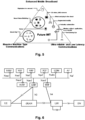
- Fig. 6 illustrates a 5G NR non-roaming reference architecture (see TS 23.501 v16.1.0, section 4.23).
- An Application Function e.g. an external application server hosting 5G services exemplary described in Fig.5 , interacts with the 3GPP Core Network in order to provide services, for example to support application influence on traffic routing, accessing Network Exposure Function (NEF) or interacting with the Policy framework for policy control (see Policy Control Function, PCF), e.g. QoS control.
- PCF Policy Control Function
- Application Functions considered to be trusted by the operator can be allowed to interact directly with relevant Network Functions.
- Application Functions not allowed by the operator to access directly the Network Functions use the external exposure framework via the NEF to interact with relevant Network Functions.
- Fig. 6 shows further functional units of the 5G architecture, namely Network Slice Selection Function (NSSF), Network Repository Function (NRF), Unified Data Management (UDM), Authentication Server Function (AUSF), Access and Mobility Management Function (AMF), Session Management Function (SMF), and Data Network (DN), e.g. operator services, Internet access or 3rd party services.
- NSSF Network Slice Selection Function
- NRF Network Repository Function
- UDM Unified Data Management
- AUSF Authentication Server Function
- AMF Access and Mobility Management Function
- SMF Session Management Function
- DN Data Network
- a terminal or user terminal, or user device is referred to in the LTE and NR as a user equipment (UE).
- UE user equipment
- This may be a mobile device or communication apparatus such as a wireless phone, smartphone, tablet computer, or an USB (universal serial bus) stick with the functionality of a user equipment.
- the term mobile device is not limited thereto, in general, a relay may also have functionality of such mobile device, and a mobile device may also work as a relay.
- a base station is a network node, e.g. forming a part of the network for providing services to terminals.
- a base station is a network node or scheduling node, which provides wireless access to terminals. Communication between the terminal and the base station is typically standardized.
- the wireless interface protocol stack includes physical layer, medium access layer (MAC) and higher layers.
- MAC medium access layer
- control plane higher-layer protocol Radio Resource Control protocol is provided.
- RRC Radio Resource Control protocol
- the base station can control configuration of the terminals and terminals may communicate with the base station to perform control tasks such as connection and bearer establishment, modification, or the like, measurements, and other functions.
- the terminology used in LTE is eNB (or eNodeB), while the currently used terminology for 5G NR is gNB.
- channels Services for transfer of data provided by a layer to the higher layers are usually referred to as channels.
- the LTE and the NR distinguish logical channels provided for higher layers by the MAC layer, transport channels provided by the physical layer to the MAC layer and physical channels which define mapping on the physical resources.
- Logical channels are different kinds of data transfer services as offered by MAC. Each logical channel type is defined by what type of information is transferred. Logical channels are classified into two groups: Control Channels and Traffic Channels. Control channels are used for the transfer of control plane information only. Traffic channels are used for the transfer of user plane information only.
- Logical Channels are then mapped by the MAC layer onto transport channels.
- logical traffic channels and some logical control channels may be mapped onto the transport channel referred to as downlink shared channel DL-SCH in downlink and onto the transport channel referred to as uplink shared channel UL-SCH in uplink.
- the PDCCH monitoring is done by the UE so as to identify and receive information intended for the UE, such as the control information as well as the user traffic (e.g. the DCI on the PDCCH, and the user data on the PDSCH indicated by the PDCCH).
- the control information e.g. the DCI on the PDCCH, and the user data on the PDSCH indicated by the PDCCH.
- Control information in the downlink (can be termed downlink control information, DCI) has the same purpose in 5G NR as the DCI in LTE, namely being a special set of control information that e.g. schedules a downlink data channel (e.g. the PDSCH) or an uplink data channel (e.g. PUSCH).
- DCI downlink control information
- 5G NR there are a number of different DCI Formats defined already (see TS 38.212 v15.6.0 section 7.3.1).
- the PDCCH monitoring of each of these functions serves a particular purpose and is thus started to said end.
- the PDCCH monitoring is typically controlled at least based on a timer, operated by the UE.
- the timer has the purpose of controlling the PDCCH monitoring, e.g. limiting the maximum amount of time that the UE is to monitor the PDCCH. For instance, the UE may not need to indefinitely monitor the PDCCH, but may stop the monitoring after some time so as to be able to save power.
- a timer may be started when the UE starts the PDCCH monitoring for the intended purpose. Then, when the timer expires, the UE may stop the PDCCH monitoring for the intended purpose, and has the opportunity to save power.
- a RAN-based paging procedure e.g. based on RAN-based notification areas
- a core-network-based paging procedure see for instance 3GPP TS 38.300 v15.6.0, TS 38.304 v15.4.0, and TS 38.331 v15.6.0 referring to RAN paging and CN paging in several sections thereof, such as section 9.2.5 "Paging" in TS 38.300).
- Paging allows the network to reach UEs in RRC_IDLE and RRC_INACTIVE state through Paging messages, and to notify UEs in RRC_IDLE, RRC_INACTIVE, and RRC_CONNECTED state of system information change and public warning information (such as ETWS/CMAS, Earthquake and Tsunami Warning System/ Commercial Mobile Alert System) indications through Short Messages.
- P-RNTI Paging-Radio Network Temporary identifier
- PCCH Paging Control Channel
- Paging DRX is defined where the UE in RRC_IDLE or RRC_INACTIVE is only required to monitor paging channels during one Paging Occasion (PO) per DRX cycle (see 3GPP TS 38.304 v15.3.0, e.g. sections 6.1 and 7.1).
- PO Paging Occasion
- the POs of a UE for CN-initiated and RAN-initiated paging are based on the same UE ID, resulting in overlapping POs for both.
- the number of different POs in a DRX cycle is configurable via system information, and a network may distribute UEs to those POs based on their IDs.
- a PO is a set of PDCCH monitoring occasions and can consist of multiple time slots (e.g. subframe or OFDM symbol) where paging DCI can be sent.
- One Paging Frame (PF) is one Radio Frame and may contain one or multiple PO(s) or starting point of a PO.
- the UE When in RRC_CONNECTED, the UE monitors the paging channels in any PO signaled in system information for a System Information (SI) change indication and/or a PWS (Public Warning System) notification.
- SI System Information
- PWS Public Warning System
- a UE in RRC_CONNECTED only monitors paging channels on the active BWP with common search space configured.
- the UE initiates RRC Connection Resume procedure upon receiving RAN initiated paging. If the UE receives a CN initiated paging in RRC_INACTIVE state, the UE moves to RRC_IDLE and informs NAS.
- the UE is configured with the PF and the PO semi-statically with respect to SFN (System Frame Number), based on formula including SFN, UE_ID, and other RRC configured parameters.
- SFN System Frame Number
- the PF and PO for paging are determined by the following formulae (cf. section 7.1 of 38.304 v15.3.0, User Equipment (UE) procedures in Idle mode and RRC Inactive state, 2019-03):
- i_s floor UE _ ID / N mod Ns .
- the PDCCH monitoring occasions for paging are determined according to pagingSearchSpace as specified in 3GPP TS 38.213: "NR; Physical layer procedures for control” V15.5.0 , and firstPDCCH-MonitoringOccasionOfPO if configured as specified in 3GPP TS 38.331: "NR; Radio Resource Control (RRC) - Protocol Specification” V15.6.0 .
- SearchSpaceld 0 is configured for pagingSearchSpace
- the PDCCH monitoring occasions for paging are same as for RMSI as defined in clause 13 in TS 38.213.
- Ns is either 1 or 2.
- a PO is a set of 'S' consecutive PDCCH monitoring occasions where 'S' is the number of actual transmitted SSBs determined according to ssb-PositionsInBurst in SIB1 (System Information Block 1).
- the K th PDCCH monitoring occasion for paging in the PO corresponds to the K th transmitted SSB.
- the PDCCH monitoring occasions for paging which do not overlap with UL symbols are sequentially numbered from zero starting from the first PDCCH monitoring occasion for paging in the PF.
- the starting PDCCH monitoring occasion number of (i_s + 1) th PO is the (i_s + 1) th value of the firstPDCCH-MonitoringOccasionOfPO parameter; otherwise, it is equal to i_s * S.
- a PO associated with a PF may start in the PF or after the PF.
- the PDCCH monitoring occasions for a PO can span multiple radio frames.
- SearchSpaceId other than 0 is configured for paging-SearchSpace the PDCCH monitoring occasions for a PO can span multiple periods of the paging search space.
- Ns Parameters Ns , nAndPagingFrameOffset, and the length of default DRX Cycle are signaled in SIB1 (System Information Block 1).
- the values of N and PF_offset are derived from the parameter nAndPagingFrameOffset as defined in 3GPP TS 38.331: "NR; Radio Resource Control (RRC) - Protocol Specification" V15.6.0 .
- the parameter first-PDCCH-MonitoringOccasionOfPO is signalled in SIB1 for paging in initial DL BWP. For paging in a DL BWP other than the initial DL BWP, the parameter first-PDCCH-MonitoringOccasionOfPO is signaled in the corresponding BWP configuration.
- 5G-S-TMSI Temporal Mobile Subscriber Identity
- 3GPP TS 23.501 System Architecture for the 5G System; Stage 2" V15.6.0 .
- 5G-S-TMSI shall in the formulae above be interpreted as a binary number where the left most bit represents the most significant bit.
- the paging DCI is contained in a set of resources generally called CORESET (COnfiguration REsource SET).
- CORESET configuration REsource SET
- the paging CORESET can be transmitted in different OFMD symbols (hereafter symbols) within the slot. Its duration is fixed when the paging CORESET is configured. Thus, to indicate a UE the exact time-location of the paging CORESET to be monitored, an indication with resolution of symbols is required.
- NR-based operation in an unlicensed spectrum is studied (see e.g. 3GPP TR 38.889, Study on NR-based access to unlicensed spectrum, v16.0.0 ).
- NR-U may operate in a sub-7 GHz band at 5 GHz or 6 GHz.
- the present disclosure is not restricted to a particular band and may also be applied to a millimeter wave band at e.g. 52 GHz.
- the Listen-Before-Talk (LBT) procedure is defined as a mechanism by which a device such as a base station or a user equipment (UE) applies a clear channel assessment (CCA) check before using the channel.
- the CCA utilizes at least energy detection to determine the presence or absence of other signals on a channel in order to determine if a channel is occupied or clear, respectively.
- European and Japanese regulations, for instance, mandate the usage of LBT in the unlicensed bands. Apart from regulatory requirements, this carrier sensing via LBT is one way for fair sharing of the unlicensed spectrum, and hence it is considered to be a vital feature for fair and friendly operation in the unlicensed spectrum in a single global solution framework.
- the channel is considered occupied if the detected energy level exceeds a configured CCA threshold (e.g. for Europe, -73dBm/MHz, see ETSI 301 893, under clause 4.8.3), and conversely is considered to be free if the detected power level is below the configured CCA threshold. If the channel is classified as free, the device is allowed to transmit immediately. The maximum transmit duration is restricted in order to facilitate fair resource sharing with other devices operating on the same band.
- a configured CCA threshold e.g. for Europe, -73dBm/MHz, see ETSI 301 893, under clause 4.8.
- the initiating device may share the acquired time-frequency resources with responding devices (e.g. one or more transceiver devices such as UEs). Sharing the acquired time-frequency resources may facilitate allowing flexible resource usage among uplink (UL) and downlink (DL). For instance, DL and UL resources can be re-allocated based on the traffic demand in the respective directions.
- responding devices e.g. one or more transceiver devices such as UEs.
- Sharing the acquired time-frequency resources may facilitate allowing flexible resource usage among uplink (UL) and downlink (DL). For instance, DL and UL resources can be re-allocated based on the traffic demand in the respective directions.
- the UE may not be possible for the UE to be paged on time because the available resources may be insufficient as they may not match the configured resources.
- the UE may be configured to monitor more paging time instances. However, this may increase the UE's power consumption associated with the additional monitoring unnecessarily. For instance, the additional paging time instances might be blocked due to LBT failure. Also, there may be no need for paging the UE.
- the present disclosure provides techniques for configuration and validation of paging resources for unlicensed operation such as NR-unlicensed.
- UEs and scheduling nodes such as base stations and corresponding methods are described for the new radio access technology envisioned for the 5G mobile communication systems such as 3GPP NR, but which may also be used in LTE mobile communication systems.
- a communication device such as a UE and a scheduling node may comprise a transceiver and circuitry such as processing circuitry.
- the transceiver in turn may comprise and/or function as a receiver and a transmitter.
- the processing circuitry may be one or more pieces of hardware such as one or more processors or any LSIs (Large Scale integration). Between the transceiver and the processing circuitry there is an input/output point (or node) over which the processing circuitry, when in operation, can control the transceiver, i.e. control the receiver and/or the transmitter and exchange reception/transmission data.
- the transceiver may include the RF (radio frequency) front including one or more antennas, amplifiers, RF modulators/demodulators and the like.
- the processing circuitry may implement control tasks such as controlling the transceiver to transmit user data and control data provided by the processing circuitry and/or receive user data and control data, which is further processed by the processing circuitry.
- the processing circuitry may also be responsible for performing other processes such as determining, deciding, calculating, measuring, etc.
- the transmitter may be responsible for performing the process of transmitting and other processes related thereto.
- the receiver may be responsible for performing the process of receiving and other processes related thereto, such as monitoring a channel.
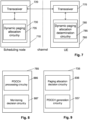
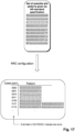
- a user equipment (UE) 760 and a scheduling node 710 are shown in Fig. 7 .
- the user equipment 760 comprises a transceiver 770 and circuitry 780 (which will also be referred to as “UE transceiver” and “UE circuitry” in this application).
- the UE transceiver 770 in operation, receives at least one PDCCH from which allocation of a paging time instance to be monitored for a paging DCI is determinable.
- the UE circuitry 780 in operation, determines the allocation of the paging time instance to be monitored based on the received at least one PDCCH.
- the UE transceiver performs monitoring for the paging DCI based on the result of the determination of the paging time instance.
- the scheduling node 710 comprises a transceiver 720 (also referred to as “scheduling node transceiver") and circuitry 730 ("scheduling node circuitry").
- the scheduling node circuitry 730 in operation, performs allocation of a paging time instance to be monitored by a user equipment, UE, for paging downlink control information, DCI, and generates at least one physical downlink control channel, PDCCH, from which the allocation of the paging time instance to be monitored is determinable.
- the transceiver in operation, transmits the at least one PDCCH, and performs transmission of the paging DCI based on the received at least one PDCCH.
- Base stations such as eNB or gNB are examples of scheduling nodes according to the present disclosure.
- UE and scheduling node perform communication over channel such as a wireless channel of a communication system such as NR, LTE, or similar radio communication systems.
- the UE circuitry may for instance comprise dynamic paging allocation determination circuitry 785
- the scheduling node circuitry 730 may comprise dynamic paging allocation circuitry 735.
- Exemplary dynamic paging allocation circuitry 735 of a scheduling node is shown in Fig. 8 , comprising paging allocation decision circuitry 836 and PDCCH generation circuitry 837.
- Exemplary PDCCH dynamic paging allocation determination circuitry 785 shown in Fig. 10 comprises PDCCH processing circuitry 886 and monitoring decision circuitry 887.
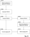
- paging methods to be performed by a user equipment and a base station which are shown in Fig. 10 .
- the paging method for the scheduling node comprises a step S1010 of performing allocation of a paging time instance to be monitored by a user equipment, UE, for paging downlink control information, DCI and a step S1020 of generating at least one physical downlink control channel, PDCCH, from which the allocation of the paging time instance to be monitored is determinable.
- the scheduling node transmits transmitting the at least one PDCCH.
- the paging method for a UE includes a step S1040 of receiving the at least one PDCCH from which allocation of a paging time instance to be monitored for paging downlink control information, DCI, is determinable.
- the UE paging method includes a step S1050 of determining the allocation of the paging time instance to be monitored based on the received at least one PDCCH.
- the paging method for the scheduling node includes, step S1060, performing transmission of the paging DCI in accordance with the allocation of the paging time instance, and correspondingly, the UE paging method, step S1070, includes performing monitoring for the paging DCI based on the determination of the allocation of the paging time instance.
- the "paging DCI" is transmitted/received via a paging PDCCH. Accordingly, the UE monitors the paging PDCCH for the paging DCI.
- the Paging DCI may contains scheduling information for a paging message (which is transmitted via a PDSCH channel) typically. If paging message is sufficiently short, the paging DCI itself may contain the paging message. In such case, no scheduling information in the paging DCI needs to be provided.
- the above-mentioned “at least one PDCCH”, which may be called “allocation determination PDCCH” for determining allocation of the paging time instance to be monitored is a PDCCH different from the paging PDCCH.
- the at least one PDCCH includes scheduling information based on which time instances for monitoring the paging PDCCH become known to the UE. Examples for the at least one PDCCH for determining allocation of the paging time instance or instances will be provided in this disclosure.
- performing allocation of a paging time instance to be monitored includes deciding whether or not one or more UEs are to be paged and whether or not a paging DCI will be allocated to a paging time instance.
- determining the allocation of the paging time instance includes determining whether or not the paging DCI is allocated to any paging time instance. Consequently "performing transmission in accordance with the allocation of the paging time instance" and “performing reception based on the determination of the allocation of the paging time instance” include transmitting and omitting the transmission and, respectively, the monitoring of the paging PDCCH.
- paging time instance which comprises a resource or resources in time domain which are configured or scheduled to be monitored by one or more UEs for a paging PDCCH carrying a paging DCI.
- the allocation determination PDCCH may indicate one or more symbols within a slot or one or more symbols respectively within a plurality of slots, wherein the slot or slots may for instance be comprised by a channel occupancy time (COT) of the scheduling node.
- COT channel occupancy time
- a paging time instance corresponds to a paging occasion (PO) within a paging frame (PF) or a paging PDCCH monitoring occasion within a PO comprising one or more symbols.
- a paging time instance may also be referred to as "paging monitoring occasion", “paging PDCCH monitoring occasion”, or "paging DCI monitoring occasion”.
- the techniques of the present disclosure may facilitate fully utilizing the COT to accommodate more channels signals with respect to semi-satically allocating the time instances. For instance, resources which would otherwise be semi-statically assigned to paging time instances may be used for different signals or channels. Furthermore, a separate LBT procedure and a COT used only for paging may be avoided.
- dynamic allocation may facilitate control for resource utilization by the scheduling node or gNB.
- the dynamic allocation in accordance with this disclosure may facilitate saving UE power by not monitoring for paging unnecessarily, e.g. by providing more precise information on allocation of paging time instances to the UE.
- dynamic allocation includes, firstly, indication of new time instances, "new" meaning that the paging time instance or instances have not been configured, e.g. semi-statically, and, secondly, enabling or disabling of semi-statically configured time instances that have been configured before acquiring of the COT by the base station. Further, indication of new time instances and enabling or disabling of configured time instances may be combined.
- the at least one PDCCH for determining allocation of a paging time instance (or instances) may carry at least one of:
- an idle UE in RRC_IDLE and RRC_INACTIVE receiving a COT structure indication interprets an indication of a symbol as "downlink” as a paging time instance to be monitored, and interprets an indication of a symbol as "uplink” or “Flexible” as a symbol which is not to be monitored for paging.
- the at least one PDCCH may carry both a COT structure indication and a paging indication.
- the COT structure indication and the paging indication may be included in the same PDCCH, or in respectively different PDCCHs, or in the same PDCCH but with a different CRC scrambling RNTI.
- both COT structure indication and paging indication are used to determine the paging time instances to be monitored.
- Indicated or enabled paging time instances (e.g. time instances represented as "downlink" in the COT structure) may further need to be validated by the paging indication.
- a configuration from RRC signaling indicates a plurality of paging occasions, and the allocation determination PDCCH (or PDCCHs) informs the UE which of these paging occasions are enabled and thus should be monitored or disabled and thus should not be monitored.
- the allocation determination PDCCH determines enabling or disabling may depend on whether a configured paging occasion is assumed, by default, by standard or by configuration to be invalid (not to be monitored without contrary indication in dynamic signaling) or valid (to be monitored without contrary indication in dynamic signaling).
- the allocation determination PDCCH is a CO-PDCCH (channel occupancy PDCCH) which includes the COT structure allocation indicating the allocation of DL, UL, and flexible symbols for one or a more slots included by the COT acquired by the scheduling node, e.g. gNB serving the UE.
- the UE receives the CO-PDCCH which includes the allocation of DL, UL, and Flexible symbols for the one or more slots.
- the UE determines that the configured paging time instance is disabled. For instance, if the UE receives a CO-PDCCH, all future paging time instances (paging time instances received later or subsequent in time to the symbols on which the CO-PDCCH is received, or the beginning of the first symbol in time of the CO-PDCCH) within the COT indicated by the CO PDCCH are disabled one the CO-PDCCH is received, regardless of the content of the CO-PDCCH. However, the UE may still be paged if it receives a paging PDCCH on a configured paging time instance preceding the CO-PDCCH in time.
- the paging time instances configuration spans over 6 slots and contains a total of 12 configured time instances for paging.
- the paging time instances are grouped into 3 paging clusters, each paging cluster covering all transmitted beams (four beams in this example).
- a "paging cluster” is a pattern of paging time instances possibly associated with a plurality of beams, which may span over one or more slots (e.g. two slots as in Fig. 11 ).
- one paging cluster comprises, for each transmitted beam, a respective paging time instance. Accordingly, by indicating disabling a paging cluster, one paging time instance per beam is disabled.
- the paging cluster could be a sub-set of the PO.
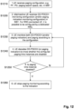
- Fig. 12 An exemplary flow chart of method steps to be performed by a UE according to embodiments where the CO-PDCCH indicates disabling of paging time instances is shown in Fig. 12 .
- paging configuration e.g. PF, PO, paging search space, etc.
- SIB1 paging configuration
- the UE assumes that resources for paging, e.g. the configured paging time instances are enabled.
- an idle or inactive UE receives a CO-PDCCH monitoring configuration (and/or paging indication monitoring configuration) in SIB1.
- SIB1 For RRC-connected UE, it is possible to be configured by a dedicated RRC.
- the UE still semi-statically receives a configuration of a paging time instance by RRC (with respect to SFN/slot index or SSB transmission window, as mentioned above).
- RRC with respect to SFN/slot index or SSB transmission window, as mentioned above.
- these configured time instances are not valid and thus not to be used for monitoring the paging PDCCH without an enabling step by dynamic allocation.
- the UE receives a CO-PDCCH including a COT structure indication which includes an allocation of DL, UL, and Flexible symbols for one or more slots.
- a paging time instance is then considered to be enabled for monitoring a paging PDCCH if the paging time instance is indicated as DL symbol(s) by the CO-PDCCH, otherwise it is not valid, and monitoring of the invalid paging time instance is not to be performed by the UE.
- the UE receives a paging indication which indicates whether or not a configured paging time instance is to be enabled or which paging time instances among preconfigured paging time instances are enabled.
- the paging indication can be a bitmap indication, similar to the paging indication used in the above-described embodiments where the configured paging time instances are dynamically disabled via PDCCH.
- the paging indication may be transmitted inside a CO-PDCCH, or in a separate PDCCH, or the same PDCCH but CRC scrambled by a separate RNTI.
- the UE does not need to monitor paging unless explicitly indicated to do so. This may facilitate, for instance, saving UE power.
- the UE In multi-beam operation, the UE needs to know, when some time instance is enabled, which beam corresponds to which time instance. Like in the embodiments using dynamically disabling, the correspondence of beams to time instances may be known based on a known pattern, as described above. Accordingly, a UE may not need to monitor paging time instances corresponding to different beams than the beam received by the UE although they have been enabled.
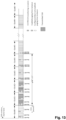
- FIG. 13 An example for dynamically enabling configured paging time instances is shown in Fig. 13 .
- the paging time instances configuration spans over 6 slot and contains a total of 12 configured paging time instances. Since four beams are transmitted, there are 3 configured paging time instances per beam. In the example of Fig. 13 , no paging cluster is formed. However, in such a case, the configured paging time instances can be enabled individually.
- configured paging time instances are enabled in slot#3 and slot#4, whereas configured paging time instances are not enabled in slot #1 and slot#2.
- an exemplary COT structure indication for both slot #1 and slot #2 may be "UUDDDDDUUDDDDD", and for both slot#3 and slot#4 "DDDDDDDDDDDD".
- a paging indication e.g. a bitmaps with one bit corresponding to one slot, may be used as follows: In slot#1, a paging indication indicating "001" means that paging, and monitoring of a paging PDCCH, is not enabled in the current slot (slot#1) and the next slot (slot#2), but enabled in slot #3. Correspondingly, a paging indication transmitted in slot#2 indicates "011", to mean enabling paging in slots #3 and #4. Further, a paging indication received in slot#3 would indicate "110".
- a paging indication may indicate one or more slots outside the gNB's channel occupancy time (slot#5 in this example). Accordingly, the number of bits of the bitmap need not vary depending on the distance between the slot in which the paging indication is received and the end of the COT. To avoid unnecessary monitoring of paging outside the COT, a bit referring to a slot outside the COT shall indicate "0" (corresponding to not enabling a paging time instance in this slot).
- another bit field inside paging indication or COT PDCCH can inform UE the end slot of the COT, such that UE knows where to stop monitoring any PDCCH.
- the number of bits in the bitmaps in in this example is exemplary. However, the number of bits should be sufficient to cover all paging time instances in the same beam as the beam transmitting the paging indication which precede the next paging indication on the same beam.
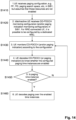
- a UE receives a paging configuration, e.g. PF, PO, paging search space, etc., in SIB1, and thus is enabled to determine the RRC-configured paging time instance(s).
- a paging configuration e.g. PF, PO, paging search space, etc.
- SIB1 paging configuration
- the UE assumes that those resources are not enabled.
- an idle/ inactive UE receives CO-PDCCH monitoring configuration (and/or paging indication monitoring configuration) in SIB1.
- CO-PDCCH monitoring configuration and/or paging indication monitoring configuration
- step S1430 the UE monitors CO-PDCCH (and/or paging indication) according to the configuration.
- step S1440 the UE decodes CO-PDCCH (or paging indication) to know whether the configured paging time instances are enabled, and determines, step S1450 whether a given paging time instance out of the configured paging time instances is enabled. If yes, the UE decodes, step S1460 a paging PDCCH on the enabled paging time instances. If no, the UE returns to step S1430 and performs monitoring of further CO-PDCCH and/or paging indications.
- a paging time instances configuration is shown where the paging time instances for the different beams are grouped into paging cluster, whereas in the configuration in Fig. 13 no paging clusters are formed.
- this choice of configurations is merely exemplary, and the embodiments of dynamically enabling and dynamically disabling paging are not limited to particular paging configurations. Accordingly, for instance, disabling via PDCCH may also be performed when no paging cluster is formed, and enabling may also be performed when paging clusters are formed.
- the COT includes a paging cluster or a plurality of paging clusters.
- Each of the paging clusters may include, for each of a plurality of beams swept by the scheduling node, respectively a configured paging time instance, and the at least one PDCCH indicates whether or not each of the plurality of paging clusters is enabled.
- the COT structure indication included in a CO PDCCH specifies the allocation of paging time instances to be monitored by a UE.
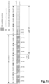
- a CO-PDCCH received by the UE and used by the scheduling node may include a specification of "new" paging time instances which have not yet been configured.
- the UE may receive, as signaling for the indication of the specified downlink symbols, a CO-PDCCH which includes a COT structure indication including an allocation of downlink and non-downlink (uplink, and Flexible) symbols, similar to the above-described CO-PDCCHs used for enabling and disabling configures time instances.
- a CO-PDCCH which includes a COT structure indication including an allocation of downlink and non-downlink (uplink, and Flexible) symbols, similar to the above-described CO-PDCCHs used for enabling and disabling configures time instances.
- the CO-PDCCH in slot#3 over beam#2 may indicate, for slot #5, "FFDDFFFFFF" to mean that the UE served over beam #2 may monitor paging over the 3rd and 4th symbols in slot#5 corresponding to beam#2.
- step S1630 the UE monitors CO-PDCCH (and optionally paging indication) according to the configuration.
- the UE then in step S1640 decodes CO-PDCCH (and optionally paging indication) to know S1650 whether any paging time instance is allocated. If no paging time instance is indicated to be allocated, the UE continues with step S1630 to monitor subsequent CO-PDCCHs and, optionally, paging indications. If an allocated paging time instance is determined in step S1650 to be indicated, the UE ay further know, from the CO-PDCCH or PDCCH including the paging indication, the corresponding beam for the indicated paging instance. In step S1670, the UE decodes paging at the indicated time instance using the corresponding beam.
- bit field in the CO-PDCCH indicates a structure spanning over more than one consecutive slots, it may be updated in a partially overlapping manner.
- a bit field in a first slot indicates structures of a first slot and a second slot
- a bit field in the second slot indicates an updated structure of the second slot and a structure for a third slot in time order.
- the configuration of the mapping of code points to slot patterns may be transmitted in CORESET#0 for idle UEs.
- the search space to be monitored for allocation determination PDCCH and/or the paging PDCCH may be the same as SS#0 or a different search space.
- the different paging allocation examples shown in Figures 11 , 13 , and 15 are applicable to each of the different above-described embodiments including enabling or disabling configured paging time instances, and dynamically specifying new paging time instances.
- the allocation of paging time instances outside the SSB window of Fig. 15 may be applied if paging time instances are configured semi-statically and enabled/disabled dynamically, and paging clusters shown in Fig. 11 are applicable to the case of dynamically specifying new paging time instances.
- the present disclosure addresses time-domain allocation of paging time instances comprising symbols to which a paging PDCCH is possibly allocated.
- resources are configured, e.g. in accordance with steps S1210, S1410, and S1610 of Figures 12 , 14 , 16 where the CORESET or search space configuration is configured.
- reception of a CORESET configuration is also received in the embodiments where configured paging time instances are enabled or disabled.
- parameters such as PF and PO, which are received in steps S1210 of Fig. 12 and S1410 of Fig. 14 , are not needed for the determination the paging time instances are to be monitored.
- the technique of implementing an integrated circuit is not limited to the LSI and may be realized by using a dedicated circuit, a general-purpose processor, or a special-purpose processor.
- a FPGA Field Programmable Gate Array
- a reconfigurable processor in which the connections and the settings of circuit cells disposed inside the LSI can be reconfigured may be used.
- the present disclosure can be realized as digital processing or analogue processing. If future integrated circuit technology replaces LSIs as a result of the advancement of semiconductor technology or other derivative technology, the functional blocks could be integrated using the future integrated circuit technology. Biotechnology can also be applied.
- the present disclosure can be realized by any kind of apparatus, device or system having a function of communication, which is referred to as a communication apparatus.
- Such a communication apparatus include a phone (e.g., cellular (cell) phone, smart phone), a tablet, a personal computer (PC) (e.g., laptop, desktop, netbook), a camera (e.g., digital still/video camera), a digital player (digital audio/video player), a wearable device (e.g., wearable camera, smart watch, tracking device), a game console, a digital book reader, a telehealth/telemedicine (remote health and medicine) device, and a vehicle providing communication functionality (e.g., automotive, airplane, ship), and various combinations thereof.
- a phone e.g., cellular (cell) phone, smart phone
- a tablet e.g., a personal computer (PC) (e.g., laptop, desktop, netbook)
- a camera e.g., digital still/video camera
- a digital player digital audio/video player
- a wearable device e.g., wearable camera, smart watch, tracking device
- the communication apparatus is not limited to be portable or movable, and may also include any kind of apparatus, device or system being non-portable or stationary, such as a smart home device (e.g., an appliance, lighting, smart meter, control panel), a vending machine, and any other "things" in a network of an "Internet of Things (IoT)".
- a smart home device e.g., an appliance, lighting, smart meter, control panel
- vending machine e.g., a vending machine, and any other "things” in a network of an "Internet of Things (IoT)".
- IoT Internet of Things
- the communication may include exchanging data through, for example, a cellular system, a wireless LAN system, a satellite system, etc., and various combinations thereof.
- the communication apparatus may comprise a device such as a controller or a sensor which is coupled to a communication device performing a function of communication described in the present disclosure.
- the communication apparatus may comprise a controller or a sensor that generates control signals or data signals which are used by a communication device performing a communication function of the communication apparatus.
- a user equipment comprising a transceiver which, in operation, receives at least one physical downlink control channel, PDCCH from which allocation of a paging time instance to be monitored for paging downlink control information, DCI, is determinable, and circuitry which, in operation, determines the allocation of the paging time instance to be monitored based on the received at least one PDCCH, wherein the transceiver, in operation, performs monitoring for the paging DCI based on the determination of the allocation of the paging time instance.
- PDCCH physical downlink control channel
- DCI downlink control information
- the UE operates on an unlicensed frequency.
- the at least one PDCCH includes at least one of a channel occupancy time, COT, structure indication indicating an allocation of downlink symbols and non-downlink symbols for a COT of a scheduling node serving the user equipment in unlicensed operation and a paging indication indicating whether or not the paging time instance is to be monitored.
- the circuitry determines at least one allocated downlink symbol indicated by the COT structure indication to be the paging time instance to be monitored.
- the paging time instance is configured via RRC signaling, and the at least one PDCCH indicates enabling or disabling the configured paging time instance.
- the circuitry determines that the paging DCI is allocated to the configured paging time instance unless the at least one PDCCH indicates that allocation of the paging DCI to the configured paging time instance is disabled.
- the circuitry determines that the configured paging time instance is disabled.
- the circuitry determines that the paging DCI is allocated to the configured paging time instance if the at least one PDCCH indicates that allocation of the paging DCI to the configured paging time instance is enabled.
- the COT includes a plurality of paging clusters each of which includes, for each of a plurality of beams swept by the scheduling node, a configured respective paging time instance, and the at least one PDCCH indicates whether or not each of the plurality of paging clusters is enabled.
- the COT structure indication specifies the allocation of the paging time instance to be monitored.
- the at least one PDCCH is a beam-specific PDCCH transmitted on one beam out of a plurality of beams swept by the scheduling node, and the allocation of the at least one downlink symbol which the circuitry determines to be the paging time instance to be monitored is beam-specific.
- the at least one PDCCH is common to a plurality of beams swept by the scheduling node and indicates a plurality of downlink symbols including, for each of the plurality of beams, a respective paging time instance to be monitored and a starting beam for which the paging time instance to be monitored is allocated to an first symbol in time out the plurality of beams, and the circuitry, in operation, determines the paging time instance to be monitored based on a configured circular order of beams beginning from the indicated starting beam.
- a scheduling node comprising circuitry which, in operation, performs allocation of a paging time instance to be monitored by a user equipment, UE, for paging downlink control information, DCI, and generates at least one physical downlink control channel, PDCCH, from which the allocation of the paging time instance to be monitored is determinable, and a transceiver which, in operation, transmits the at least one PDCCH and performs transmission of the paging DCI in accordance with the allocation of the paging time instance.
- the scheduling node operates on an unlicensed frequency
- the transceiver in operation, performs a listen before talk, LBT, operation
- the circuitry in operation acquires a channel occupancy time based on a result of the LBT operation, and allocates the paging time instance to be monitored for the paging DCI to resources within the COT.
- the at least one PDCCH includes at least one of a channel occupancy time, COT, structure indication indicating an allocation of downlink symbols and non-downlink symbols for a COT of a scheduling node serving the user equipment in unlicensed operation and a paging indication indicating whether or not the paging time instance is to be monitored.
- At least one allocated downlink symbol is indicated by the COT structure indication to be determined as the paging time instance to be monitored.
- the paging time instance is configured via RRC signaling, and the at least one PDCCH indicates enabling or disabling the configured paging time instance.
- the paging DCI is allocated to the configured paging time instance unless the at least one PDCCH indicates that allocation of the paging DCI to the configured paging time instance is disabled.
- the configured paging time instance is allocated to a symbol subsequent to the at least one PDCCH within the COT.
- the paging DCI is allocated to the configured paging time instance if the at least one PDCCH indicates that allocation of the paging DCI to the configured paging time instance is enabled.
- the COT includes a plurality of paging clusters each of which includes, for each of a plurality of beams swept by the scheduling node, a configured respective paging time instance, and the at least one PDCCH indicates whether or not each of the plurality of paging clusters is enabled.
- the COT structure indication specifies the allocation of the paging time instance to be monitored.
- the at least one PDCCH is a beam-specific PDCCH transmitted on one beam out of a plurality of beams swept by the scheduling node, and the allocation of the at least one downlink symbol which the circuitry determines to be the paging time instance to be monitored is beam-specific.
- the at least one PDCCH is common to a plurality of beams swept by the scheduling node and indicates a plurality of downlink symbols including, for each of the plurality of beams, a respective paging time instance to be monitored and a starting beam for which the paging time instance to be monitored is allocated to an first symbol in time out the plurality of beams, and the circuitry, in operation, specifies the paging time instance to be monitored in accordance with a configured circular order of beams beginning from the indicated starting beam.
- a paging method to be performed by a user equipment, UE comprising receiving at least one physical downlink control channel, PDCCH from which allocation of a paging time instance to be monitored for paging downlink control information, DCI, is determinable, determining the allocation of the paging time instance to be monitored based on the received at least one PDCCH, and performing monitoring for the paging DCI based on the determination of the allocation of the paging time instance.
- PDCCH physical downlink control channel
- DCI downlink control information
- the method is performed during operation on an unlicensed frequency.
- the at least one PDCCH includes at least one of a channel occupancy time, COT, structure indication indicating an allocation of downlink symbols and non-downlink symbols for a COT of a scheduling node serving the user equipment in unlicensed operation and a paging indication indicating whether or not the paging time instance is to be monitored.
- At least one allocated downlink symbol indicated by the COT structure indication is determined to be the paging time instance to be monitored.
- the paging time instance is configured via RRC signaling, and the at least one PDCCH indicates enabling or disabling the configured paging time instance.
- the paging DCI is allocated to the configured paging time instance unless the at least one PDCCH indicates that allocation of the paging DCI to the configured paging time instance is disabled.
- the at least one PDCCH includes the COT structure indication and the configured paging time instance is allocated to a symbol subsequent to the at least one PDCCH within the COT, it is determined that the configured paging time instance is disabled.
- the COT includes a plurality of paging clusters each of which includes, for each of a plurality of beams swept by the scheduling node, a configured respective paging time instance, and the at least one PDCCH indicates whether or not each of the plurality of paging clusters is enabled.
- the COT structure indication specifies the allocation of the paging time instance to be monitored.
- the at least one PDCCH is common to a plurality of beams swept by the scheduling node and indicates a plurality of downlink symbols including, for each of the plurality of beams, a respective paging time instance to be monitored and a starting beam for which the paging time instance to be monitored is allocated to an first symbol in time out the plurality of beams, and the the paging time instance to be monitored is determined based on a configured circular order of beams beginning from the indicated starting beam.
- a paging method to be performed by a scheduling node comprising performing allocation of a paging time instance to be monitored by a user equipment, UE, for paging downlink control information, DCI, generating at least one physical downlink control channel, PDCCH, from which the allocation of the paging time instance to be monitored is determinable, and transmitting the at least one PDCCH; and performing transmission of the paging DCI in accordance with the allocation of the paging time instance.
- the at least one PDCCH includes at least one of a channel occupancy time, COT, structure indication indicating an allocation of downlink symbols and non-downlink symbols for a COT of a scheduling node serving the user equipment in unlicensed operation and a paging indication indicating whether or not the paging time instance is to be monitored.
- At least one allocated downlink symbol is indicated by the COT structure indication to be determined as the paging time instance to be monitored.
- the paging time instance is configured via RRC signaling, and the at least one PDCCH indicates enabling or disabling the configured paging time instance.
- the paging DCI is allocated to the configured paging time instance unless the at least one PDCCH indicates that allocation of the paging DCI to the configured paging time instance is disabled.
- the configured paging time instance is allocated to a symbol subsequent to the at least one PDCCH within the COT.
- the paging DCI is allocated to the configured paging time instance if the at least one PDCCH indicates that allocation of the paging DCI to the configured paging time instance is enabled.
- the COT includes a plurality of paging clusters each of which includes, for each of a plurality of beams swept by the scheduling node, a configured respective paging time instance, and the at least one PDCCH indicates whether or not each of the plurality of paging clusters is enabled.
- the at least one PDCCH is a beam-specific PDCCH transmitted on one beam out of a plurality of beams swept by the scheduling node, and the allocation of the at least one downlink symbol which the circuitry determines to be the paging time instance to be monitored is beam-specific.
- the at least one PDCCH is common to a plurality of beams swept by the scheduling node and indicates a plurality of downlink symbols including, for each of the plurality of beams, a respective paging time instance to be monitored and a starting beam for which the paging time instance to be monitored is allocated to an first symbol in time out the plurality of beams, and the paging time instance to be monitored is specified in accordance with a configured circular order of beams beginning from the indicated starting beam.
- the UE comprises a transceiver which, in operation, receives at least one physical downlink control channel, PDCCH from which allocation of a paging time instance to be monitored for paging downlink control information, DCI, is determinable, and circuitry which, in operation, determines the allocation of the paging time instance to be monitored based on the received at least one PDCCH, wherein the transceiver, in operation, performs monitoring for the paging DCI based on the determination of the allocation of the paging time instance.
- PDCCH physical downlink control channel
- DCI downlink control information
Landscapes
- Engineering & Computer Science (AREA)
- Computer Networks & Wireless Communication (AREA)
- Signal Processing (AREA)
- Mobile Radio Communication Systems (AREA)
Applications Claiming Priority (3)
| Application Number | Priority Date | Filing Date | Title |
|---|---|---|---|
| EP19189894.9A EP3772228A1 (de) | 2019-08-02 | 2019-08-02 | Benutzergerät und planungsknoten |
| EP20740055.7A EP4008141B1 (de) | 2019-08-02 | 2020-07-20 | Benutzergerät und planungsknoten |
| PCT/EP2020/070458 WO2021023501A1 (en) | 2019-08-02 | 2020-07-20 | User equipment and scheduling node |
Related Parent Applications (2)
| Application Number | Title | Priority Date | Filing Date |
|---|---|---|---|
| EP20740055.7A Division-Into EP4008141B1 (de) | 2019-08-02 | 2020-07-20 | Benutzergerät und planungsknoten |
| EP20740055.7A Division EP4008141B1 (de) | 2019-08-02 | 2020-07-20 | Benutzergerät und planungsknoten |
Publications (2)
| Publication Number | Publication Date |
|---|---|
| EP4529348A2 true EP4529348A2 (de) | 2025-03-26 |
| EP4529348A3 EP4529348A3 (de) | 2025-06-18 |
Family
ID=67544062
Family Applications (3)
| Application Number | Title | Priority Date | Filing Date |
|---|---|---|---|
| EP19189894.9A Withdrawn EP3772228A1 (de) | 2019-08-02 | 2019-08-02 | Benutzergerät und planungsknoten |
| EP25155848.2A Pending EP4529348A3 (de) | 2019-08-02 | 2020-07-20 | Benutzergerät und planungsknoten |
| EP20740055.7A Active EP4008141B1 (de) | 2019-08-02 | 2020-07-20 | Benutzergerät und planungsknoten |
Family Applications Before (1)
| Application Number | Title | Priority Date | Filing Date |
|---|---|---|---|
| EP19189894.9A Withdrawn EP3772228A1 (de) | 2019-08-02 | 2019-08-02 | Benutzergerät und planungsknoten |
Family Applications After (1)
| Application Number | Title | Priority Date | Filing Date |
|---|---|---|---|
| EP20740055.7A Active EP4008141B1 (de) | 2019-08-02 | 2020-07-20 | Benutzergerät und planungsknoten |
Country Status (5)
| Country | Link |
|---|---|
| US (1) | US20220279480A1 (de) |
| EP (3) | EP3772228A1 (de) |
| JP (2) | JP7682153B2 (de) |
| ES (1) | ES3026671T3 (de) |
| WO (1) | WO2021023501A1 (de) |
Families Citing this family (8)
| Publication number | Priority date | Publication date | Assignee | Title |
|---|---|---|---|---|
| US11849481B2 (en) * | 2019-08-08 | 2023-12-19 | Qualcomm Incorporated | Techniques for configuring multiple-SCS and multi-beam direction communications |
| WO2021217598A1 (en) * | 2020-04-30 | 2021-11-04 | Lenovo (Beijing) Limited | Emtc scheduling and mpdcch monitoring |
| US12262347B2 (en) * | 2021-05-10 | 2025-03-25 | Qualcomm Incorporated | Paging based on cross-slot scheduling |
| US20250184961A1 (en) * | 2021-08-24 | 2025-06-05 | Ntt Docomo, Inc. | Terminal and communication method |
| EP4412137A4 (de) * | 2021-09-30 | 2025-08-20 | Lg Electronics Inc | Verfahren und vorrichtung zum senden oder empfangen eines drahtlossignals in einem drahtloskommunikationssystem |
| CN118120309A (zh) * | 2021-09-30 | 2024-05-31 | 株式会社电装 | 终端、基站以及无线通信方法 |
| WO2025022584A1 (ja) * | 2023-07-25 | 2025-01-30 | 株式会社Nttドコモ | 端末、基地局、及び通信方法 |
| WO2025161653A1 (en) * | 2024-01-31 | 2025-08-07 | Mediatek Inc. | Method and apparatus for idle mode operations associated with low-power synchronization signal and physical broadcast channel block cluster in mobile communications |
Family Cites Families (22)
| Publication number | Priority date | Publication date | Assignee | Title |
|---|---|---|---|---|
| US20160050667A1 (en) * | 2014-08-18 | 2016-02-18 | Samsung Electronics Co., Ltd. | Communication on licensed and unlicensed bands |
| WO2018144873A1 (en) * | 2017-02-02 | 2018-08-09 | Convida Wireless, Llc | Apparatuses for transmission of paging blocks in swept downlink beams |
| CN118338425A (zh) * | 2017-05-03 | 2024-07-12 | 交互数字专利控股公司 | 用于新无线电(nr)中的寻呼过程的方法和设备 |
| US20190104500A1 (en) * | 2017-10-02 | 2019-04-04 | Telefonaktiebolaget Lm Ericsson (Publ) | Efficient Paging Configuration |
| WO2019099661A1 (en) * | 2017-11-15 | 2019-05-23 | Idac Holdings, Inc. | Enhanced paging monitoring in 5g |
| WO2019096672A1 (en) * | 2017-11-15 | 2019-05-23 | Sony Corporation | Telecommunications apparatus and methods |
| US11324009B2 (en) | 2017-11-17 | 2022-05-03 | Telefonaktiebolaget Lm Ericsson (Publ) | Efficient CORESET configuration |
| CN109661031B (zh) * | 2017-11-17 | 2020-06-16 | 华为技术有限公司 | 传输寻呼消息的方法、终端设备和网络设备 |
| EP3512272A1 (de) * | 2018-01-12 | 2019-07-17 | Panasonic Intellectual Property Corporation of America | Benutzergerät und basisstation zur unterstützung von netzwerksegmenten und teilnahme an funkrufverfahren und verbindungsaufbau |
| CN119729774A (zh) * | 2018-05-11 | 2025-03-28 | 诺基亚技术有限公司 | 寻呼时机开始确定 |
| RU2763448C1 (ru) * | 2018-06-21 | 2021-12-29 | Телефонактиеболагет Лм Эрикссон (Пабл) | Обеспечение распределенных событий опроса |
| US11658789B2 (en) * | 2018-08-09 | 2023-05-23 | Lg Electronics Inc. | Method for transmitting physical uplink shared channel of terminal in unlicensed band and device using same method |
| WO2020089854A1 (en) * | 2018-11-01 | 2020-05-07 | Telefonaktiebolaget Lm Ericsson (Publ) | Handling multiple transmission opportunities in a paging occasion |
| CN111713124A (zh) * | 2019-01-18 | 2020-09-25 | Oppo广东移动通信有限公司 | 用于非授权频谱的无线通信方法和设备 |
| US11297613B2 (en) * | 2019-01-31 | 2022-04-05 | Qualcomm Incorporated | Beam definition for directional communications |
| US11343853B2 (en) * | 2019-02-13 | 2022-05-24 | Qualcomm Incorporated | Sharing a transmission opportunity of a wireless communication medium |
| US11516770B2 (en) * | 2019-02-22 | 2022-11-29 | Qualcomm Incorporated | Paging opportunity monitoring |
| CN114009099B (zh) * | 2019-04-01 | 2024-06-04 | 瑞典爱立信有限公司 | 在RRC_Idle/Inactive中用于新空口(NR)用户设备(UE)功率节省的增强的寻呼时机(PO)监测 |
| US11997643B2 (en) * | 2019-04-04 | 2024-05-28 | FG Innovation Company Limited | Method and apparatus for performing paging monitoring in radio access networks |
| US20220070783A1 (en) * | 2019-04-25 | 2022-03-03 | Mediatek Inc. | Nr paging early indicator |
| EP3963970A1 (de) * | 2019-04-30 | 2022-03-09 | Nokia Technologies Oy | Funkruf auf einem schmalen strahl und ausrichtung mit standard-drx |
| CN114128367B (zh) * | 2019-08-01 | 2024-10-18 | 瑞典爱立信有限公司 | 用于虚假寻呼减少的用户设备(ue)分组准则和机制 |
-
2019
- 2019-08-02 EP EP19189894.9A patent/EP3772228A1/de not_active Withdrawn
-
2020
- 2020-07-20 JP JP2022506815A patent/JP7682153B2/ja active Active
- 2020-07-20 WO PCT/EP2020/070458 patent/WO2021023501A1/en not_active Ceased
- 2020-07-20 EP EP25155848.2A patent/EP4529348A3/de active Pending
- 2020-07-20 EP EP20740055.7A patent/EP4008141B1/de active Active
- 2020-07-20 US US17/630,097 patent/US20220279480A1/en active Pending
- 2020-07-20 ES ES20740055T patent/ES3026671T3/es active Active
-
2025
- 2025-05-13 JP JP2025080431A patent/JP2025118842A/ja active Pending
Non-Patent Citations (2)
| Title |
|---|
| "3GPP TS 38.213: ''NR; Physical layer procedures for control", RADIO RESOURCE CONTROL (RRC) - PROTOCOL SPECIFICATION |
| "3GPP TS 38.331", NR; RADIO RESOURCE CONTROL (RRC) - PROTOCOL SPECIFICATION |
Also Published As
| Publication number | Publication date |
|---|---|
| EP4008141A1 (de) | 2022-06-08 |
| JP2022543258A (ja) | 2022-10-11 |
| EP4008141C0 (de) | 2025-03-19 |
| WO2021023501A1 (en) | 2021-02-11 |
| JP7682153B2 (ja) | 2025-05-23 |
| EP4008141B1 (de) | 2025-03-19 |
| JP2025118842A (ja) | 2025-08-13 |
| EP4529348A3 (de) | 2025-06-18 |
| US20220279480A1 (en) | 2022-09-01 |
| ES3026671T3 (en) | 2025-06-11 |
| EP3772228A1 (de) | 2021-02-03 |
Similar Documents
| Publication | Publication Date | Title |
|---|---|---|
| EP4008141B1 (de) | Benutzergerät und planungsknoten | |
| EP4136913B1 (de) | Steuerressourcensatz null für new-radio-vorrichtungen mit reduzierter kapazität | |
| JP7043746B2 (ja) | 通信装置、通信方法及びコンピュータプログラム | |
| KR20210124243A (ko) | 2-단계 랜덤 액세스와 4-단계 랜덤 액세스 간의 공존을 지원하기 위한 기법들 | |
| US20220369291A1 (en) | Terminal and communication method | |
| EP4090129A1 (de) | Benutzergerät, planungsknoten, verfahren für benutzergeräte und verfahren zur planung von knoten | |
| JP7594002B2 (ja) | 端末及び通信方法 | |
| EP3893422A1 (de) | Kommunikationsvorrichtung und basisstation | |
| US20220256557A1 (en) | Communication apparatuses and communication methods for dci for v2x communication apparatuses | |
| US20250254705A1 (en) | Terminal, and communication method | |
| EP4322669A1 (de) | Benutzergerät, planungsknoten, verfahren für benutzergerät und verfahren zur planung von knoten | |
| EP3800942A1 (de) | Benutzergerät und planungsknoten | |
| US12356424B2 (en) | Terminal and communication method | |
| JP2023547058A (ja) | ページングに関与するユーザ機器および基地局 | |
| US20250247831A1 (en) | Base station, terminal, and communication method | |
| US20240187075A1 (en) | User equipment and scheduling node | |
| US20250267638A1 (en) | Communication device, and communication method | |
| US20250056511A1 (en) | Base station, terminal and communication method | |
| US20230300859A1 (en) | Terminal and sidelink communication control method | |
| US20220272729A1 (en) | Terminal and communication method | |
| EP4564974A1 (de) | Endgerät, basisstation und kommunikationsverfahren | |
| EP4572478A1 (de) | Kommunikationsvorrichtung und kommunikationsverfahren | |
| EP4572482A1 (de) | Kommunikationsvorrichtung und kommunikationsverfahren | |
| EP4507433A1 (de) | Anzeige unbenutzter übertragungsgelegenheiten für pusch-wiederholung | |
| WO2025004717A1 (ja) | 端末、基地局、及び、通信方法 |
Legal Events
| Date | Code | Title | Description |
|---|---|---|---|
| PUAI | Public reference made under article 153(3) epc to a published international application that has entered the european phase |
Free format text: ORIGINAL CODE: 0009012 |
|
| STAA | Information on the status of an ep patent application or granted ep patent |
Free format text: STATUS: REQUEST FOR EXAMINATION WAS MADE |
|
| 17P | Request for examination filed |
Effective date: 20250204 |
|
| AC | Divisional application: reference to earlier application |
Ref document number: 4008141 Country of ref document: EP Kind code of ref document: P |
|
| AK | Designated contracting states |
Kind code of ref document: A2 Designated state(s): AL AT BE BG CH CY CZ DE DK EE ES FI FR GB GR HR HU IE IS IT LI LT LU LV MC MK MT NL NO PL PT RO RS SE SI SK SM TR |
|
| REG | Reference to a national code |
Ref country code: DE Ref legal event code: R079 Free format text: PREVIOUS MAIN CLASS: H04W0088080000 Ipc: H04W0068020000 |
|
| PUAL | Search report despatched |
Free format text: ORIGINAL CODE: 0009013 |
|
| AK | Designated contracting states |
Kind code of ref document: A3 Designated state(s): AL AT BE BG CH CY CZ DE DK EE ES FI FR GB GR HR HU IE IS IT LI LT LU LV MC MK MT NL NO PL PT RO RS SE SI SK SM TR |
|
| RIC1 | Information provided on ipc code assigned before grant |
Ipc: H04W 88/08 20090101ALI20250512BHEP Ipc: H04W 88/02 20090101ALI20250512BHEP Ipc: H04W 68/02 20090101AFI20250512BHEP |