EP4529318A1 - Datenübertragungsverfahren, -vorrichtung und -system - Google Patents
Datenübertragungsverfahren, -vorrichtung und -system Download PDFInfo
- Publication number
- EP4529318A1 EP4529318A1 EP23815145.0A EP23815145A EP4529318A1 EP 4529318 A1 EP4529318 A1 EP 4529318A1 EP 23815145 A EP23815145 A EP 23815145A EP 4529318 A1 EP4529318 A1 EP 4529318A1
- Authority
- EP
- European Patent Office
- Prior art keywords
- resource
- service
- periodicity
- terminal device
- logical channel
- Prior art date
- Legal status (The legal status is an assumption and is not a legal conclusion. Google has not performed a legal analysis and makes no representation as to the accuracy of the status listed.)
- Pending
Links
Images


Classifications
-
- H—ELECTRICITY
- H04—ELECTRIC COMMUNICATION TECHNIQUE
- H04W—WIRELESS COMMUNICATION NETWORKS
- H04W72/00—Local resource management
- H04W72/04—Wireless resource allocation
-
- H—ELECTRICITY
- H04—ELECTRIC COMMUNICATION TECHNIQUE
- H04W—WIRELESS COMMUNICATION NETWORKS
- H04W72/00—Local resource management
- H04W72/20—Control channels or signalling for resource management
-
- H—ELECTRICITY
- H04—ELECTRIC COMMUNICATION TECHNIQUE
- H04W—WIRELESS COMMUNICATION NETWORKS
- H04W72/00—Local resource management
- H04W72/20—Control channels or signalling for resource management
- H04W72/23—Control channels or signalling for resource management in the downlink direction of a wireless link, i.e. towards a terminal
-
- H—ELECTRICITY
- H04—ELECTRIC COMMUNICATION TECHNIQUE
- H04W—WIRELESS COMMUNICATION NETWORKS
- H04W72/00—Local resource management
- H04W72/40—Resource management for direct mode communication, e.g. D2D or sidelink
-
- H—ELECTRICITY
- H04—ELECTRIC COMMUNICATION TECHNIQUE
- H04W—WIRELESS COMMUNICATION NETWORKS
- H04W72/00—Local resource management
- H04W72/50—Allocation or scheduling criteria for wireless resources
- H04W72/54—Allocation or scheduling criteria for wireless resources based on quality criteria
-
- H—ELECTRICITY
- H04—ELECTRIC COMMUNICATION TECHNIQUE
- H04W—WIRELESS COMMUNICATION NETWORKS
- H04W88/00—Devices specially adapted for wireless communication networks, e.g. terminals, base stations or access point devices
- H04W88/02—Terminal devices
- H04W88/04—Terminal devices adapted for relaying to or from another terminal or user
-
- H—ELECTRICITY
- H04—ELECTRIC COMMUNICATION TECHNIQUE
- H04W—WIRELESS COMMUNICATION NETWORKS
- H04W92/00—Interfaces specially adapted for wireless communication networks
- H04W92/16—Interfaces between hierarchically similar devices
- H04W92/18—Interfaces between hierarchically similar devices between terminal devices
Definitions
- One user equipment (user equipment, UE) (for example, referred to as a remote UE) may access a network via another UE (for example, referred to as a relay UE).
- the relay UE is connected to the remote UE through a radio interface (for example, a proximity-based services communication 5 (proximity-based services communication 5, PC5) interface), the relay UE is connected to a network device through a radio interface (for example, a Uu interface), and the remote UE may establish a connection to the network device via the relay UE, to perform data transmission.
- a radio interface for example, a proximity-based services communication 5 (proximity-based services communication 5, PC5) interface
- the relay UE is connected to a network device through a radio interface (for example, a Uu interface)
- the remote UE may establish a connection to the network device via the relay UE, to perform data transmission.
- the remote UE when the remote UE is to transmit uplink data, the remote UE sends the uplink data to the relay UE that provides a relay service for the remote UE. After receiving the uplink data, the relay UE requests an uplink resource from the network device. After the relay UE receives the uplink resource scheduled by the network device, the uplink resource may be preferentially used to transmit other high-priority data (for example, uplink data of the relay UE, or for another example, uplink data of another remote UE). In this case, the uplink resource scheduled by the network device is not used to send the uplink data of the remote UE. As a result, an overall uplink transmission delay of the remote UE significantly increases, and experience of the remote UE is affected.
- This application provides a data transmission method, an apparatus, and a system, to reduce a transmission delay of uplink data of a remote UE.
- a data transmission method is provided.
- the method may be performed by a network device, or may be performed by a component (for example, a chip or a circuit) of a network device. This is not limited.
- a component for example, a chip or a circuit
- the method may include: The network device sends information about a first resource to a first terminal device, where the information about the first resource indicates that the first resource is used to transmit a first service of the first terminal device, and the first resource is used to transmit the first service between the first terminal device and a second terminal device.
- the network device sends information about a second resource to the second terminal device, where the information about the second resource indicates that the second resource is used to transmit the first service, and the second resource is used to transmit the first service between the network device and the second terminal device.
- the network device receives the first service from the first terminal device via the second terminal device.
- the first resource is used to transmit the first service between the first terminal device and the second terminal device.
- the first terminal device sends the first service to the second terminal device by using the first resource
- the second terminal device receives the first service from the first terminal device by using the first resource.
- the second resource is used to transmit the first service between the network device and the second terminal device.
- the second terminal device sends the first service to the network device by using the second resource, and correspondingly, the network device receives the first service from the second terminal device by using the second resource.
- the network device receives the first service from the first terminal device via the second terminal device.
- the network device receives data of the first service from the first terminal device via the second terminal device.
- the network device may jointly configure the first resource and the second resource for the first service of the first terminal device.
- the first terminal device may directly send the data of the first service by using the first resource
- the second terminal device may directly send the data of the first service to the network device by using the second resource, so that the data of the first service is directly transmitted based on the first resource and the second resource, thereby reducing a transmission delay of the data of the first service, and improving user experience.
- the first service has a first correspondence with the first resource.
- the first correspondence is a correspondence between a quality of service QoS flow corresponding to the first service and a first logical channel.
- the first logical channel is a logical channel using the first resource.
- the first logical channel is a corresponding logical channel for transmitting data of the first service between the first terminal device and the second terminal device.
- the QoS flow corresponding to the first service has the correspondence with the first logical channel.
- data on the first logical channel can be the data of the first service, and the first resource can be totally used to transmit the data of the first service as much as possible, to ensure transmission performance for the data of the first service.
- the method further includes: The network device sends the first correspondence to the first terminal device.
- that the information about the first resource indicates that the first resource is used to transmit the first service includes: The information about the first resource indicates that the first logical channel uses the first resource.
- the first logical channel is the corresponding logical channel for transmitting the data of the first service between the first terminal device and the second terminal device.
- the network device may further send the information about the first resource to the first terminal device, where the information about the first resource indicates that the corresponding logical channel (that is, the first logical channel) for transmitting the data of the first service between the first terminal device and the second terminal device uses the first resource.
- the first resource can be used to transmit the data of the first service, to ensure the transmission performance for the data of the first service as much as possible.
- the first service has a second correspondence with the second resource.
- the second correspondence is a correspondence between a data radio bearer corresponding to the first service and a second logical channel.
- the second logical channel is a logical channel using the second resource.
- the second logical channel is a corresponding logical channel for transmitting the data of the first service between the second terminal device and the network device.
- the data radio bearer corresponding to the first service has the correspondence with the second logical channel.
- data on the second logical channel can be the data of the first service
- the second resource can be totally used to transmit the data of the first service as much as possible, to ensure the transmission performance for the data of the first service.
- the method further includes: The network device sends the second correspondence to the second terminal device.
- that the information about the second resource indicates that the second resource is used to transmit the first service includes: The information about the second resource indicates that the second logical channel uses the second resource.
- the second logical channel is the corresponding logical channel for transmitting the data of the first service between the second terminal device and the network device.
- the network device may further send the information about the second resource to the second terminal device, where the information about the second resource indicates that the corresponding logical channel (that is, the second logical channel) for transmitting the data of the first service between the second terminal device and the network device uses the second resource.
- the second resource can be used to transmit the data of the first service, to ensure the transmission performance for the data of the first service as much as possible.
- the method further includes: The network device sends information about a third resource to the first terminal device, where the information about the third resource indicates that the third resource is used to transmit the first service, and the third resource is used to transmit the first service between the network device and the first terminal device.
- the third resource is used to transmit the first service between the network device and the first terminal device.
- the first terminal device sends the first service to the network device by using the third resource, and correspondingly, the network device receives the first service from the first terminal device by using the third resource.
- a transmission resource jointly configured by the network device for the first service of the first terminal device further includes the third resource, and the third resource may be used to transmit the first service between the first terminal device and the network device.
- the first terminal device may directly send the data of the first service to the network device by using the third resource, to reduce a transmission delay of the data of the first service and improve user experience.
- the first service has a third correspondence with the third resource.
- the third correspondence is a correspondence between the quality of service QoS flow corresponding to the first service and a third logical channel.
- the third logical channel is a logical channel using the third resource.
- the third logical channel is a corresponding logical channel for transmitting the data of the first service between the first terminal device and the network device.
- the QoS flow corresponding to the first service has the correspondence with the third logical channel.
- data on the third logical channel can be the data of the first service, and the third resource can be totally used to transmit the data of the first service as much as possible, to ensure transmission performance for the data of the first service.
- the method further includes: The network device sends the third correspondence to the first terminal device.
- that the information about the third resource indicates that the third resource is used to transmit the first service includes: The information about the third resource indicates that the third logical channel uses the third resource.
- the third logical channel is the corresponding logical channel for transmitting the data of the first service between the first terminal device and the network device.
- the network device may further send the information about the third resource to the first terminal device, where the information about the third resource indicates that the corresponding logical channel (that is, the third logical channel) for transmitting the data of the first service between the first terminal device and the network device uses the third resource.
- the third resource can be used to transmit the data of the first service, to ensure the transmission performance for the data of the first service as much as possible.
- a periodicity of the second resource is the same as a periodicity of the first resource, or a periodicity of the second resource is in an integer multiple relationship with a periodicity of the first resource.
- the first service is a periodically transmitted service.
- the periodicity of the second resource and/or the periodicity of the first resource are/is the same as a periodicity of the first service, or the periodicity of the second resource and/or the periodicity of the first resource are/is an integer multiple of a periodicity of the first service.
- the first service is a periodically transmitted service.
- a periodicity of the third resource satisfies at least one of the following: The periodicity of the third resource is the same as a periodicity of the first resource, or the periodicity of the third resource is in an integer multiple relationship with a periodicity of the first resource; the periodicity of the third resource is the same as a periodicity of the second resource, or the periodicity of the third resource is in an integer multiple relationship with a periodicity of the second resource; or the periodicity of the third resource is the same as a periodicity of the first service, or the periodicity of the third resource is an integer multiple of a periodicity of the first service.
- a time domain resource start position of the first resource is after a time domain resource start position of the second resource.
- a time gap between the time domain start position of the second resource and the time domain start position of the first resource is t time units, and t is an integer greater than or equal to 1.
- the second resource is an uplink configured grant UL CG resource
- the first resource is a sidelink configured grant SL CG resource.
- a data transmission method may be performed by a terminal device, or may be performed by a component (for example, a chip or a circuit) of a terminal device. This is not limited. For ease of description, an example in which the method is performed by a first terminal device and a second terminal device is used below for description.
- the method may include: The first terminal device receives information about a first resource from a network device, where the information about the first resource indicates that the first resource is used to transmit a first service of the first terminal device, and the first resource is used to transmit the first service between the first terminal device and the second terminal device.
- the second terminal device receives information about a second resource from the network device, where the information about the second resource indicates that the second resource is used to transmit the first service, and the second resource is used to transmit the first service between the network device and the second terminal device.
- the first terminal device sends the first service to the second terminal device by using the first resource.
- the second terminal device receives the first service, and sends the first service to the network device by using the second resource.
- the first service has a first correspondence with the first resource.
- the first correspondence is a correspondence between a quality of service QoS flow corresponding to the first service and a first logical channel.
- the first logical channel is a logical channel using the first resource.
- the first logical channel is a corresponding logical channel for transmitting data of the first service between the first terminal device and the second terminal device.
- that the information about the first resource indicates that the first resource is used to transmit the first service includes: The information about the first resource indicates that the first logical channel uses the first resource.
- the first logical channel is the corresponding logical channel for transmitting the data of the first service between the first terminal device and the second terminal device.
- that the information about the second resource indicates that the second resource is used to transmit the first service includes: The information about the second resource indicates that the second logical channel uses the second resource.
- the second logical channel is the corresponding logical channel for transmitting the data of the first service between the second terminal device and the network device.
- the first service has a third correspondence with the third resource.
- the third correspondence is a correspondence between the quality of service QoS flow corresponding to the first service and a third logical channel.
- the third logical channel is a logical channel using the third resource.
- the third logical channel is a corresponding logical channel for transmitting the data of the first service between the first terminal device and the network device.
- the method further includes: The first terminal device receives the third correspondence from the network device.
- that the information about the third resource indicates that the third resource is used to transmit the first service includes: The information about the third resource indicates that the third logical channel uses the third resource.
- the third logical channel is the corresponding logical channel for transmitting the data of the first service between the first terminal device and the network device.
- a periodicity of the second resource is the same as a periodicity of the first resource, or a periodicity of the second resource is in an integer multiple relationship with a periodicity of the first resource.
- the first service is a periodically transmitted service.
- the periodicity of the second resource and/or the periodicity of the first resource are/is the same as a periodicity of the first service, or the periodicity of the second resource and/or the periodicity of the first resource are/is an integer multiple of a periodicity of the first service.
- the first service is a periodically transmitted service.
- a periodicity of the third resource satisfies at least one of the following: The periodicity of the third resource is the same as a periodicity of the first resource, or the periodicity of the third resource is in an integer multiple relationship with a periodicity of the first resource; the periodicity of the third resource is the same as a periodicity of the second resource, or the periodicity of the third resource is in an integer multiple relationship with a periodicity of the second resource; or the periodicity of the third resource is the same as a periodicity of the first service, or the periodicity of the third resource is an integer multiple of a periodicity of the first service.
- a time domain start position of the second resource is after a time domain start position of the first resource.
- a time gap between the time domain start position of the second resource and the time domain start position of the first resource is t time units, and t is an integer greater than or equal to 1.
- the first service is a periodically transmitted service.
- the second resource is an uplink configured grant UL CG resource
- the first resource is a sidelink configured grant SL CG resource.
- the third resource is an uplink configured grant UL CG resource.
- a data transmission method is provided.
- the method may be performed by a terminal device, or may be performed by a component (for example, a chip or a circuit) of a terminal device. This is not limited.
- a component for example, a chip or a circuit
- the method may include: The first terminal device receives information about a first resource from a network device, where the information about the first resource indicates that the first resource is used to transmit a first service of the first terminal device, and the first resource is used to transmit the first service between the first terminal device and a second terminal device.
- the first terminal device sends the first service to the network device via the second terminal device, where a resource used by the first terminal device to send the first service to the second terminal device is the first resource, a resource used by the second terminal device to send the first service to the network device is a second resource, and the second resource is a resource that is configured by the network device and that is used to transmit the first service between the network device and the second terminal device.
- the first service has a first correspondence with the first resource.
- the first correspondence is a correspondence between a quality of service QoS flow corresponding to the first service and a first logical channel.
- the first logical channel is a logical channel using the first resource.
- the first logical channel is a corresponding logical channel for transmitting data of the first service between the first terminal device and the second terminal device.
- the method further includes: The first terminal device receives the first correspondence from the network device.
- that the information about the first resource indicates that the first resource is used to transmit the first service includes: The information about the first resource indicates that the first logical channel uses the first resource.
- the first logical channel is the corresponding logical channel for transmitting the data of the first service between the first terminal device and the second terminal device.
- the method further includes: The first terminal device receives information about a third resource from the network device, where the information about the third resource indicates that the third resource is used to transmit the first service, and the third resource is used to transmit the first service between the network device and the first terminal device.
- the first terminal device sends the first service to the network device by using the third resource.
- the first service has a third correspondence with the third resource.
- the third correspondence is a correspondence between the quality of service QoS flow corresponding to the first service and a third logical channel.
- the third logical channel is a logical channel using the third resource.
- the third logical channel is a corresponding logical channel for transmitting the data of the first service between the first terminal device and the network device.
- the method further includes: The first terminal device receives the third correspondence from the network device.
- that the information about the third resource indicates that the third resource is used to transmit the first service includes: The information about the third resource indicates that the third logical channel uses the third resource.
- the third logical channel is the corresponding logical channel for transmitting the data of the first service between the first terminal device and the network device.
- a periodicity of the second resource is the same as a periodicity of the first resource, or a periodicity of the second resource is in an integer multiple relationship with a periodicity of the first resource.
- the first service is a periodically transmitted service.
- the periodicity of the second resource and/or the periodicity of the first resource are/is the same as a periodicity of the first service, or the periodicity of the second resource and/or the periodicity of the first resource are/is an integer multiple of a periodicity of the first service.
- the first service is a periodically transmitted service.
- a periodicity of the third resource satisfies at least one of the following: The periodicity of the third resource is the same as a periodicity of the first resource, or the periodicity of the third resource is in an integer multiple relationship with a periodicity of the first resource; the periodicity of the third resource is the same as a periodicity of the second resource, or the periodicity of the third resource is in an integer multiple relationship with a periodicity of the second resource; or the periodicity of the third resource is the same as a periodicity of the first service, or the periodicity of the third resource is an integer multiple of a periodicity of the first service.
- a time domain start position of the second resource is after a time domain start position of the first resource.
- a time gap between the time domain start position of the second resource and the time domain start position of the first resource is t time units, and t is an integer greater than or equal to 1.
- the first service is a periodically transmitted service.
- the second resource is an uplink configured grant UL CG resource
- the first resource is a sidelink configured grant SL CG resource.
- the third resource is an uplink configured grant UL CG resource.
- a data transmission method is provided.
- the method may be performed by a terminal device, or may be performed by a component (for example, a chip or a circuit) of a terminal device. This is not limited.
- a component for example, a chip or a circuit
- the method may include: The first terminal device receives information about a third resource from a network device, where the information about the third resource indicates that the third resource is used to transmit a first service of the first terminal device, and the third resource is used to transmit the first service between the network device and the first terminal device.
- the first terminal device sends first data of the first service to the network device by using the third resource.
- the first terminal device sends second data of the first service to the network device via a second terminal device, where a resource used by the second terminal device to send the first service to the network device is a second resource, the second resource is a resource that is configured by the network device and that is used to transmit the first service between the network device and the second terminal device, and the first data is the same as or different from the second data.
- that the first data is the same as the second data may indicate that the first data is partially the same as the second data, or may indicate that the first data is totally the same as the second data.
- that the first data is different from the second data may indicate that the first data is partially different from the second data, or may indicate that the first data is totally different from the second data.
- the network device may jointly configure a transmission resource for the data. Specifically, the network device configures a resource used by the first terminal device to send the data to the second terminal device, and the network device configures a resource used by the first terminal device to directly send the data to the network device. In this way, when the data needs to be transmitted, the third resource and the second resource that are jointly configured may be directly used for transmission.
- the first service has a third correspondence with the third resource.
- the third correspondence is a correspondence between a quality of service QoS flow corresponding to the first service and a third logical channel.
- the third logical channel is a logical channel using the third resource.
- the third logical channel is a corresponding logical channel for transmitting the data of the first service between the first terminal device and the network device.
- the method further includes: The first terminal device receives the third correspondence from the network device.
- that the information about the third resource indicates that the third resource is used to transmit the first service includes: The information about the third resource indicates that the third logical channel uses the third resource.
- the third logical channel is the corresponding logical channel for transmitting the data of the first service between the first terminal device and the network device.
- the first service is a periodically transmitted service.
- a periodicity of the third resource satisfies at least one of the following: The periodicity of the third resource is the same as a periodicity of a first resource, or the periodicity of the third resource is in an integer multiple relationship with a periodicity of a first resource; the periodicity of the third resource is the same as a periodicity of the second resource, or the periodicity of the third resource is in an integer multiple relationship with a periodicity of the second resource; or the periodicity of the third resource is the same as a periodicity of the first service, or the periodicity of the third resource is an integer multiple of a periodicity of the first service.
- the first service is a periodically transmitted service.
- the second resource is an uplink configured grant UL CG resource
- the third resource is an uplink configured grant UL CG resource.
- a data transmission method is provided.
- the method may be performed by a terminal device, or may be performed by a component (for example, a chip or a circuit) of a terminal device. This is not limited.
- a component for example, a chip or a circuit
- the method may include: The second terminal device receives information about a second resource from a network device, where the information about the second resource indicates that the second resource is used to transmit a first service of a first terminal device, and the second resource is used to transmit the first service between the network device and the second terminal device.
- the second terminal device receives the first service sent by the first terminal device by using a first resource, and forwards the first service to the network device by using the second resource, where the first resource is a resource that is configured by the network device and that is used to transmit the first service between the first terminal device and the second terminal device.
- the first service has a second correspondence with the second resource.
- the second correspondence is a correspondence between a data radio bearer corresponding to the first service and a second logical channel.
- the second logical channel is a logical channel using the second resource.
- the second logical channel is a corresponding logical channel for transmitting data of the first service between the second terminal device and the network device.
- the method further includes: The second terminal device receives the second correspondence from the network device.
- that the information about the second resource indicates that the second resource is used to transmit the first service includes: The information about the second resource indicates that the second logical channel uses the second resource.
- the second logical channel is the corresponding logical channel for transmitting the data of the first service between the second terminal device and the network device.
- a periodicity of the second resource is the same as a periodicity of the first resource, or a periodicity of the second resource is in an integer multiple relationship with a periodicity of the first resource.
- the first service is a periodically transmitted service.
- the periodicity of the second resource and/or the periodicity of the first resource are/is the same as a periodicity of the first service, or the periodicity of the second resource and/or the periodicity of the first resource are/is an integer multiple of a periodicity of the first service.
- a time domain start position of the second resource is after a time domain start position of the first resource.
- a time gap between the time domain start position of the second resource and the time domain start position of the first resource is t time units, and t is an integer greater than or equal to 1.
- the first service is a periodically transmitted service.
- the second resource is an uplink configured grant UL CG resource
- the first resource is a sidelink configured grant SL CG resource.
- a data transmission method is provided.
- the method may be performed by a terminal device, or may be performed by a component (for example, a chip or a circuit) of a terminal device. This is not limited.
- a component for example, a chip or a circuit
- the method may include: The first terminal device receives information about a third resource from a network device, where the information about the third resource indicates that the third resource is used to transmit a first service of the first terminal device.
- the second terminal device receives information about a second resource from the network device, where the information about the second resource indicates that the second resource is used to transmit the first service.
- the first terminal device sends first data of the first service to the network device by using the third resource, and the first terminal device sends second data of the first service to the second terminal device.
- the second terminal device receives the second data of the first service, and sends the second data of the first service to the network device by using the second resource, where the first data is the same as or different from the second data.
- that the first data is the same as the second data may indicate that the first data is partially the same as the second data, or may indicate that the first data is totally the same as the second data.
- that the first data is different from the second data may indicate that the first data is partially different from the second data, or may indicate that the first data is totally different from the second data.
- the first service has a third correspondence with the third resource.
- the third correspondence is a correspondence between a quality of service QoS flow corresponding to the first service and a third logical channel.
- the third logical channel is a logical channel using the third resource.
- the third logical channel is a corresponding logical channel for transmitting the data of the first service between the first terminal device and the network device.
- the method further includes: The first terminal device receives the third correspondence from the network device.
- that the information about the third resource indicates that the third resource is used to transmit the first service includes: The information about the third resource indicates that the third logical channel uses the third resource.
- the third logical channel is the corresponding logical channel for transmitting the data of the first service between the first terminal device and the network device.
- the first service has a second correspondence with the second resource.
- the second correspondence is a correspondence between a data radio bearer corresponding to the first service and a second logical channel.
- the second logical channel is a logical channel using the second resource.
- the second logical channel is a corresponding logical channel for transmitting data of the first service between the second terminal device and the network device.
- the method further includes: The second terminal device receives the second correspondence from the network device.
- that the information about the second resource indicates that the second resource is used to transmit the first service includes: The information about the second resource indicates that the second logical channel uses the second resource.
- the second logical channel is the corresponding logical channel for transmitting the data of the first service between the second terminal device and the network device.
- the first service is a periodically transmitted service.
- a periodicity of the third resource satisfies at least one of the following: The periodicity of the third resource is the same as a periodicity of a first resource, or the periodicity of the third resource is in an integer multiple relationship with a periodicity of a first resource; the periodicity of the third resource is the same as a periodicity of the second resource, or the periodicity of the third resource is in an integer multiple relationship with a periodicity of the second resource; or the periodicity of the third resource is the same as a periodicity of the first service, or the periodicity of the third resource is an integer multiple of a periodicity of the first service.
- the first service is a periodically transmitted service.
- the second resource is an uplink configured grant UL CG resource
- the third resource is an uplink configured grant UL CG resource.
- a data transmission apparatus configured to perform the method in any one of the possible implementations of the first aspect to the sixth aspect.
- the apparatus may include a unit and/or a module, configured to perform the method in any one of the possible implementations of the first aspect to the sixth aspect, for example, a processing unit and/or a communication unit.
- the apparatus is a communication device (for example, a network device or a terminal device).
- the communication unit may be a transceiver or an input/output interface
- the processing unit may be at least one processor.
- the transceiver may be a transceiver circuit.
- the input/output interface may be an input/output circuit.
- the apparatus is a chip, a chip system, or a circuit used in a communication device (for example, a network device or a terminal device).
- a communication device for example, a network device or a terminal device.
- the communication unit may be an input/output interface, an interface circuit, an output circuit, an input circuit, a pin, a related circuit, or the like on the chip, the chip system, or the circuit; and the processing unit may be at least one processor, a processing circuit, a logic circuit, or the like.
- a data transmission apparatus includes at least one processor, configured to execute a computer program or instructions stored in a memory, to perform the method in any one of the possible implementations of the first aspect to the sixth aspect.
- the apparatus further includes the memory, configured to store the computer program or the instructions.
- the apparatus further includes a communication interface, and the processor reads, through the communication interface, the computer program or the instructions stored in the memory.
- the apparatus is a communication device (for example, a network device or a terminal device).
- the apparatus is a chip, a chip system, or a circuit used in a communication device (for example, a network device or a terminal device).
- a communication device for example, a network device or a terminal device.
- this application provides a processor, configured to perform the method according to the foregoing aspects.
- Operations such as sending and obtaining/receiving related to the processor may be understood as operations such as output and receiving or input of the processor, or operations such as sending and receiving performed by a radio frequency circuit and an antenna, unless otherwise specified, or provided that the operations do not contradict actual functions or internal logic of the operations in related descriptions. This is not limited in this application.
- a computer-readable storage medium stores program code to be executed by a device, and the program code is used to perform the method in any one of the possible implementations of the first aspect to the sixth aspect.
- a computer program product including instructions is provided.
- the computer program product is run on a computer, the computer is enabled to perform the method in any one of the possible implementations of the first aspect to the sixth aspect.
- a communication system including at least one of the foregoing first terminal device, second terminal device, and network device.
- the technical solutions provided in this application may be applied to various communication systems, for example, a 5th generation (5th generation, 5G) or new radio (new radio, NR) system, a long term evolution (long term evolution, LTE) system, an LTE frequency division duplex (frequency division duplex, FDD) system, and an LTE time division duplex (time division duplex, TDD) system.
- 5th generation 5th generation
- NR new radio
- LTE long term evolution
- LTE frequency division duplex frequency division duplex
- FDD frequency division duplex
- TDD time division duplex
- the technical solutions provided in this application may be further applied to device-to-device (device-to-device, D2D) communication, vehicle-to-everything (vehicle-to-everything, V2X) communication, machine-to-machine (machine-to-machine, M2M) communication, machine type communication (machine type communication, MTC), an internet of things (internet of things, IoT) communication system, or another communication system.
- D2D device-to-device
- V2X vehicle-to-everything
- machine-to-machine machine-to-machine
- M2M machine type communication
- MTC machine type communication
- IoT internet of things
- a terminal device in embodiments of this application may also be referred to as a user equipment (user equipment, UE), an access terminal, a subscriber unit, a subscriber station, a mobile station, a remote station, a remote terminal, a mobile device, a user terminal, a terminal, a wireless communication device, a user agent, or a user apparatus.
- UE user equipment
- an access terminal a subscriber unit, a subscriber station, a mobile station, a remote station, a remote terminal, a mobile device, a user terminal, a terminal, a wireless communication device, a user agent, or a user apparatus.
- the terminal device may be a device that provides a user with voice/data, for example, a handheld device or a vehicle-mounted device having a wireless connection function.
- the terminal may be a mobile phone (mobile phone), a tablet computer, a notebook computer, a palmtop computer, a mobile internet device (mobile internet device, MID), a wearable device, a virtual reality (virtual reality, VR) device, an augmented reality (augmented reality, AR) device, a wireless terminal in industrial control (industrial control), a wireless terminal in self driving (self driving), a wireless terminal in remote surgery (remote medical surgery), a wireless terminal in a smart grid (smart grid), a wireless terminal in transportation safety (transportation safety), a wireless terminal in a smart city (smart city), a wireless terminal in a smart home (smart home), a cellular phone, a cordless phone, a session initiation protocol (session initiation protocol, SIP) phone, a wireless local loop (wireless local loop, WLL) station
- the terminal device may alternatively be a wearable device.
- the wearable device may also be referred to as a wearable intelligent device, and is a generic term for wearable devices that are developed through intelligent design on daily wearables by using wearable technologies, such as glasses, gloves, watches, clothing, and shoes.
- the wearable device is a portable device that can be directly worn on a body or integrated into clothes or an accessory of a user.
- the wearable device is not only a hardware device, but also implements a powerful function through software support, data exchange, and cloud interaction.
- the wearable intelligent device includes a full-featured and large-sized device that can implement all or part of functions without depending on a smartphone, for example, a smartwatch or smart glasses, and a device that is dedicated to only one type of application function and needs to be used together with another device such as a smartphone, for example, various smart bands or smart jewelry for monitoring physical signs.
- an apparatus configured to implement a function of the terminal device may be a terminal device, or may be an apparatus capable of supporting the terminal device in implementing the function, for example, a chip system or a chip.
- the apparatus may be installed in the terminal device.
- the chip system may include a chip, or may include a chip and another discrete component.
- a network device in embodiments of this application may be a device configured to communicate with the terminal device.
- the network device may also be referred to as an access network device or a radio access network device.
- the network device may be a base station.
- the network device in embodiments of this application may be a radio access network (radio access network, RAN) node (or device) that connects the terminal device to a wireless network.
- RAN radio access network
- the base station may cover the following names in a broad sense, or may be replaced with the following names, for example, a NodeB (NodeB), an evolved NodeB (evolved NodeB, eNB), a next generation NodeB (next generation NodeB, gNB), a relay station, an access point, a transmitting and receiving point (transmitting and receiving point, TRP), a transmitting point (transmitting point, TP), a primary station, a secondary station, a multi-standard radio (motor slide retainer, MSR) node, a home base station, a network controller, an access node, a radio node, an access point (access point, AP), a transmission node, a transceiver node, a baseband unit (baseband unit, BBU), a remote radio unit (remote radio unit, RRU), an active antenna unit (active antenna unit, AAU), a radio-frequency head (remote radio head, RRH), a central unit (central unit,
- the base station may be a macro base station, a micro base station, a relay node, a donor node, an analogue, or a combination thereof.
- the base station may alternatively be a communication module, a modem, or a chip that is disposed in the foregoing device or apparatus.
- the base station may alternatively be a mobile switching center, a device that bears a base station function in D2D, V2X, and M2M communication, a network side device in a 6G network, a device that bears a base station function in a future communication system, or the like.
- the base station may support networks using a same access technology or different access technologies. A specific technology and a specific device form that are used by the network device are not limited in embodiments of this application.
- the base station may be fastened or movable.
- a helicopter or an uncrewed aerial vehicle may be configured as a mobile base station, and one or more cells may move based on a location of the mobile base station.
- a helicopter or an uncrewed aerial vehicle may be configured as a device for communicating with another base station.
- the network device mentioned in embodiments of this application may be a device including a CU or a DU, a device including a CU and a DU, or a device including a control plane CU node (a central unit-control plane (central unit-control plane, CU-CP)), a user plane CU node (a central unit-user plane (central unit-user plane, CU-UP)), and a DU node.
- a control plane CU node a central unit-control plane (central unit-control plane, CU-CP)
- a user plane CU node a central unit-user plane (central unit-user plane, CU-UP)
- DU node a device including a CU or DU, a device including a control plane CU node (a central unit-control plane (central unit-control plane, CU-CP)), a user plane CU node (a central unit-user plane (central unit-user plane, CU-UP)), and a DU node.
- the network device and the terminal device may be deployed on the land, including an indoor device, an outdoor device, a handheld device, or a vehicle-mounted device; may be deployed on the water; or may be deployed on an airplane, a balloon, and a satellite in the air. Scenarios in which the network device and the terminal device are located are not limited in embodiments of this application.
- FIG. 1 and FIG. 2 Details are as follows.
- FIG. 1 is a diagram of a network architecture applicable to an embodiment of this application.
- the network architecture may include a terminal device, for example, a first terminal device and a second terminal device in FIG. 1 .
- the network architecture may further include a network device.
- the first terminal device may be referred to as a remote terminal device (remote UE), and the second terminal device may be referred to as a relay terminal device (relay UE).
- the first terminal device may communicate with the second terminal device through a communication interface #1.
- the second terminal device may communicate with the network device through a communication interface #2.
- the first terminal device may communicate with the network device via the second terminal device.
- the first terminal device may communicate with the network device through an indirect (indirect) path (a path that is based on the communication interface #1 and the communication interface #2 in FIG. 1 ).
- the architecture shown in FIG. 1 is used as an example.
- the first terminal device may first send the data to the second terminal device, and then the second terminal device forwards the data to the network device.
- FIG. 2 is a diagram of a network architecture applicable to another embodiment of this application.
- the network architecture may include but is not limited to a first terminal device, a second terminal device, and a network device.
- the first terminal device may be referred to as a remote UE, and the second terminal device may be referred to as a relay UE.
- the first terminal device may communicate with the second terminal device through a communication interface #1.
- the second terminal device may communicate with the network device through a communication interface #2.
- the first terminal device may communicate with the network device through the communication interface #2, or the first terminal device may communicate with the network device via the second terminal device.
- there are two paths between the first terminal device and the network device where one is an indirect path (a path that is based on the communication interface #1 and the communication interface #2 in FIG. 2 ) that passes through the second terminal device, and the other is a direct (direct) path (a path that is based on the communication interface #2 in FIG. 2 ) between the first terminal device and the network device.
- Data sent by the first terminal device to the network device may be sent to the network device via the second terminal device.
- data sent by the first terminal device to the network device may be sent to the network device through the communication interface #2 between the first terminal device and the network device.
- one part of data sent by the first terminal device to the network device is sent to the network device via the second terminal device, and the other part of the data is sent to the network device through the communication interface #2 between the first terminal device and the network device.
- the communication interface #1 may be a proximity-based services communication 5 (proximity-based services communication 5, PC5) interface, or may be a non-3rd generation partnership project (3rd generation partnership project, 3GPP) interface, for example, a private interface, a wireless fidelity (wireless fidelity, Wi-Fi) interface, a Bluetooth interface, or a wired interface.
- 3rd generation partnership project 3rd generation partnership project
- the communication interface #2 may be a Uu interface. The Uu interface and the PC5 interface will be described later.
- the network architectures shown in FIG. 1 and FIG. 2 are merely examples for description, and a network architecture applicable to embodiments of this application is not limited thereto.
- the technical solutions in embodiments of this application may be applied to an architecture in which one terminal device (for example, referred to as a remote UE) can communicate with another device (for example, a network device, or for another example, a terminal device) via another terminal device (for example, referred to as a relay UE).
- the foregoing architecture may further include another device, for example, a core network device and/or another terminal device.
- the core network device may include, for example, an access and mobility management function (access and mobility management function, AMF) network element, a session management function (session management function, SMF) network element, a user plane function (user plane function, UPF) network element, and a policy control function (policy control function, PCF) network element.
- AMF access and mobility management function
- SMF session management function
- UPF user plane function
- PCF policy control function
- the Uu interface may be an interface for communication between a UE and a network device.
- a link between the UE and the network device may be referred to as a Uu link.
- the Uu link is merely a name for differentiation, and a specific name of the Uu link does not limit the protection scope of this application. It may be further understood that the Uu link represents a connection relationship between the UE and the network device, and is a logical concept rather than a physical entity.
- the PC5 interface may be an interface for direct communication between UEs.
- the UEs communicate with each other through a direct link between the UEs rather than an operator network (for example, a base station).
- a link between the UEs may be referred to as a sidelink (sidelink, SL), or a link between the UEs may be referred to as a PC5 link (PC5 link).
- sidelink sidelink
- PC5 link PC5 link
- each vehicle may be considered as a UE, and vehicles (that is, between UEs) may communicate with each other through a PC5 interface rather than an operator network. In this way, a communication delay can be effectively reduced.
- FIG. 3 is a diagram of a PC5 interface and a Uu interface.
- PC5 interface and the Uu interface are merely examples, and do not constitute a limitation on the protection scope of this application.
- the communication interface may alternatively have another name. Details are not described herein again.
- the PC5 interface may support communication modes such as broadcast, unicast, and multicast. This application mainly relates to the unicast communication mode. The following briefly describes unicast communication.
- the remote UE may access the network via the relay UE in two manners: a single-path manner and a dual-path manner. What FIG. 1 shows may be understood as the single-path manner, and what FIG. 2 shows may be understood as the dual-path manner. It can be learned from FIG. 1 that the single-path manner is as follows: The remote UE communicates with a network device via the relay UE through an indirect path. It can be learned from FIG. 2 that the dual-path manner is as follows: There are two paths between the remote UE and a network device, where one is an indirect path that passes through the relay UE, and the other is a direct path between the remote UE and the network device.
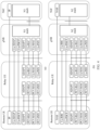
- FIG. 4 is a diagram of a user plane protocol stack for sidelink U2N relay (that is, a user plane protocol stack used when the remote UE establishes the connection to the network device via the relay UE for data transmission).
- (b) in FIG. 4 is a diagram of a control plane protocol stack for sidelink U2N relay (that is, a control plane protocol stack used when the remote UE establishes the connection to the network device via the relay UE for data transmission).
- DRB One or more radio bearers are introduced in a wireless network, to meet service quality requirements of different types of services of a terminal device.
- the radio bearers include a DRB and a signaling radio bearer (signaling radio bearer, SRB), and are used to transmit different types of service data (including control plane signaling and user plane data) between the terminal and a network device.
- SRB signaling radio bearer
- Time unit It may be one or more radio frames, one or more subframes, one or more slots, one or more mini-slots, one or more symbols, or the like.
- the symbol may be an orthogonal frequency division multiplexing (orthogonal frequency division multiplexing, OFDM) symbol, a discrete fourier transform spread spectrum orthogonal frequency division multiplexing (discrete fourier transform spread spectrum orthogonal frequency division multiplexing, DFT-S-OFDM) symbol, or the like.
- the time unit may be one second (second, s), multiple seconds, one millisecond (millisecond, ms), multiple milliseconds, or the like.
- the network device may perform scheduling by using downlink control information (downlink control information, DCI), or the network device configures a configured grant (configured grant, CG) resource through RRC.
- the CG resource includes two types (type): (1) A CG type 1: The network device configures a semi-static periodic transmission resource for the UE, and indicates the configured transmission resource to the UE through RRC. (2) A CG type 2: The network device configures a semi-static periodic transmission resource for the UE, indicates the configured transmission resource to the UE through RRC, and indicates, by using DCI, the UE to activate or deactivate the configured resource.
- the network device may schedule the resource by using the DCI after receiving the SL buffer status reported by the UE. If the UE reports, to the network device by using an RRC message, information about a periodic service model that is being performed on a PC5 interface (for example, including a service periodicity, a service information size, and a sidelink QoS flow identifier corresponding to a service), after receiving the information, the network device may configure the CG resource through RRC.
- a periodic service model for example, including a service periodicity, a service information size, and a sidelink QoS flow identifier corresponding to a service
- One or more resource pools are configured for the UE.
- the UE may determine available resources and unavailable resources in the resource pool based on a rule, and then select, from the available resources, a resource suitable for a current data transmission requirement to send data.
- Step 1 The remote UE sends the uplink data to the relay UE that provides a relay service for the remote UE.
- the remote UE may obtain an SL resource in the mode 2, and send the uplink data to the relay UE.
- Step 2 After receiving the data of the remote UE, the relay UE buffers the data, and triggers a BSR.
- the relay UE After receiving, from the PC5 interface, the uplink data sent by the remote UE, the relay UE processes the uplink data by using a protocol stack, and places the uplink data in a Uu buffer of the relay UE.
- the protocol stacks shown in (a) and (b) in FIG. 4 are used as an example.
- the relay UE receives the uplink data of the remote UE via an SL module. After being processed, the uplink data enters a Uu module, and the BSR on the Uu interface is triggered. In other words, the relay sends the BSR to the network device.
- the relay UE cannot send the BSR without an uplink resource. Therefore, the UE needs to request the resource from the network device by sending an uplink scheduling request (scheduling request, SR).
- the BSR is encapsulated in a MAC PDU and is sent to a network side through a PUSCH channel, and therefore needs the uplink resource.
- An SR signal may be transmitted in a PUCCH control channel, and therefore may be sent to the network side without the uplink resource.
- Step 3 The relay UE receives DCI scheduling of the network device, and transmits the data by using the scheduled uplink resource.
- the relay UE When the relay UE has service data of the relay UE, or the relay UE serves a plurality of remote UEs, when receiving the uplink resource scheduled by the network device, the relay UE first performs a logical channel prioritization (logical channel prioritization, LCP) process. Because a basic rule of LCP is to preferentially transmit high-priority data, the relay UE may transmit the uplink data of the relay UE by using the uplink resource (for example, the uplink data of the relay UE has a higher priority), or may transmit uplink data of another remote UE by using the uplink resource (for example, the data of the another remote UE has a higher priority).
- LCP logical channel prioritization
- the relay UE may request the uplink resource after being triggered by the remote UE, due to occurrence of other high-priority data (for example, the uplink data of the relay UE, or for another example, the uplink data of the another remote UE), the uplink resource scheduled by the network device is not used to send the uplink data of the remote UE.
- other high-priority data for example, the uplink data of the relay UE, or for another example, the uplink data of the another remote UE
- two-hop transmission of a sidelink U2N relay system that is, the remote UE sends the uplink data to the relay UE, and then the relay UE sends the uplink data to the network device
- a resource preemption problem that may occur on a relay UE side cause a significant increase in an overall uplink transmission delay of the remote UE, affecting user experience of the remote UE.
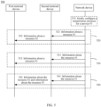
- FIG. 5 is a diagram of a data transmission method 500 according to an embodiment of this application.
- the method 500 may include the following steps.
- the method 500 includes step 520.
- a network device sends information about a resource #1 (an example of a second resource) and information about a resource #2 (an example of a first resource).
- the network device sends the information about the resource #1 to a second terminal device, and the network device sends the information about the resource #2 to a first terminal device.
- the network device sends the information about the resource #1 to a second terminal device, and the network device sends the information about the resource #2 to a first terminal device.
- the resource #1 represents a resource used to transmit data of a service #1 (an example of a first service) between the second terminal device and the network device.
- the second terminal device may send the data of the service #1 to the network device by using the resource #1.
- the network device may receive the data of the service #1 from the second terminal device by using the resource #1.
- the resource #1 may be, for example, a CG resource (for example, the resource #1 is an UL CG resource), that is, the resource #1 is a periodic transmission resource.
- the network device may configure the CG resource for the service #1, where the CG resource is used to transmit the data of the service #1 between the second terminal device and the network device.
- the resource #2 represents a resource used to transmit data of the service #1 between the second terminal device and the first terminal device.
- the first terminal device may send the data of the service #1 to the second terminal device by using the resource #2.
- the second terminal device may receive the data of the service #1 from the first terminal device by using the resource #1. Then, the second terminal device may send the data of the service #1 to the network device.
- the resource #2 may be, for example, a CG resource (for example, the resource #2 is an SL CG resource), that is, the resource #2 is a periodic transmission resource.
- the network device may configure the CG resource for the service #1, where the CG resource is used to transmit the data of the service #1 between the second terminal device and the first terminal device.
- the service #1 is a service of the first terminal device.
- the service #1 may represent one service, or may represent a plurality of services. This is not limited.
- the first terminal device may be a remote UE, and the second terminal device may be a relay UE. Details are not described below again.
- the method 500 further includes: The network device configures the resource #1 and the resource #2 for the service #1. Specifically, descriptions are provided below with reference to step 510.
- the method 500 includes step 530.
- a network device sends information about a resource #1 and information about a resource #3 (an example of a third resource).
- the network device sends the information about the resource #1 to a second terminal device, and the network device sends the information about the resource #3 to a first terminal device.
- the network device sends the information about the resource #1 to a second terminal device, and the network device sends the information about the resource #3 to a first terminal device.
- the resource #3 represents a resource used to transmit data of a service #1 between the first terminal device and the network device.
- the first terminal device may send the data of the service #1 to the network device by using the resource #3.
- the network device receives the data of the service #1 from the first terminal device by using the resource #3.
- the resource #3 may be, for example, a CG resource (for example, the resource #3 is an UL CG resource), that is, the resource #3 is a periodic transmission resource.
- the network device may configure the CG resource for the service #1, where the CG resource is used to transmit the data of the service #1 between the first terminal device and the network device.
- the method 500 further includes: The network device configures the resource #1 and the resource #3 for the service #1. Specifically, descriptions are provided below with reference to step 510.
- the method 500 includes step 540.
- a network device sends information about a resource #1, information about a resource #2, and information about a resource #3.
- the network device sends the information about the resource #1 to a second terminal device, and the network device sends the information about the resource #2 and the information about the resource #3 to a first terminal device.
- the network device sends the information about the resource #1 to a second terminal device, and the network device sends the information about the resource #2 and the information about the resource #3 to a first terminal device.
- the method 500 further includes: The network device configures the resource #1, the resource #2, and the resource #3 for a service #1. Specifically, descriptions are provided below with reference to step 510.
- the method 500 further includes step 510.
- the network device jointly configures a transmission resource for the service #1.
- the network device may further configure the resource. That the network device jointly configures the transmission resource for the service #1 may include any one of the following solutions.
- Solution 1 The network device configures the resource #1 and the resource #2 for the service #1.
- the network device may jointly configure a transmission resource for the data, that is, the network device configures resources used from sending the data by the first terminal device to receiving the data by the network device. Specifically, the network device configures a resource used by the first terminal device to send the data to the second terminal device, and the network device configures a resource used by the second terminal device to forward the data to the network device. In this way, when the data needs to be transmitted, the resource #1 and the resource #2 that are jointly configured may be directly used for transmission.
- Solution 2 The network device configures the resource #1 and the resource #3 for the service #1.
- the network device may alternatively configure the resource #2 and the resource #3 for the service #1.
- the relay UE may forward the data of the service #1 to the network device by using the resource #1 received in step 830.
- the remote UE sends first data of the service #1 to the network device, and the remote UE sends second data of the service #1 to the network device via the relay UE, where the first data is partially the same as the second data.
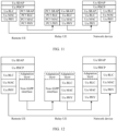
- FIG. 12 is another diagram of a protocol stack applicable to an embodiment of this application.
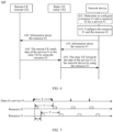
- FIG. 13 is a diagram of the data transmission method 1300 according to still another embodiment of this application.
- the method 1300 may be applicable to the foregoing solution 3, that is, a network device jointly configures a resource #1, a resource #2, and a resource #3.
- the method 1300 may include the following steps.
- the network device configures the resource #1, the resource #2, and the resource #3.
- step 610 in the method 600 For solutions related to the resource #1 and the resource #2, refer to related descriptions of step 610 in the method 600. Details are not described herein again.
- step 810 in the method 800 For a solution related to the resource #3, refer to related descriptions of step 810 in the method 800. Details are not described herein again.
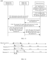
- n" 2.
- T1, T2, and T3 may be greater than T, for example, are n"*T.
- data of the service #1 is periodically transmitted.
- a remote UE periodically sends the data of the service #1 to the network device, and the periodicity is T.
- the periodicity of the resource #1 in time domain is T
- the periodicity of the resource #2 in time domain is also T
- the periodicity of the resource #3 in time domain is also T.
- Form 2 The periodicity of the resource #1, the periodicity of the resource #2, and the periodicity of the resource #3 are not all the same (for example, the periodicity of the resource #1, the periodicity of the resource #2, and the periodicity of the resource #3 are all different, or for another example, some of the periodicity of the resource #1, the periodicity of the resource #2, and the periodicity of the resource #3 are the same).
- a time domain start position of the resource #1 is after a time domain start position of the resource #2.
- a relay UE may have time to process the data by using a corresponding protocol stack.
- a time gap between the time domain start position of the resource #1 and the time domain start position of the resource #2 is t time units.
- FIG. 14 is used as an example. As shown in FIG. 14 , an interval between the resource #1 and the resource #2 in time domain is t. In other words, an interval between a periodicity boundary of the resource #1 and a periodicity boundary of the resource #2 is t.
- the information about the resource #2 and the information about the resource #3 may be transmitted by using a same piece of signaling (for example, carried in a same RRC reconfiguration message), or may be transmitted by using different signaling (for example, carried in different RRC reconfiguration messages). This is not limited.
- step 1320 refer to related descriptions of step 620 and step 820. Details are not described herein again.
- the network device sends information about the resource #1 to the relay UE.
- step 1330 refer to related descriptions of step 630. Details are not described herein again.
- the method 1300 further includes step 1301: The network device determines to configure the resource #1, the resource #2, and the resource #3 for the service #1.
- the network device determines, based on a service feature of the service #1, to jointly configure the resource #1, the resource #2, and the resource #3 for the service #1. For example, if the network device determines that the service #1 is a periodically transmitted service, the network device jointly configures the resource #1, the resource #2, and the resource #3 for the service #1.
- the network device determines that the service #1 is a periodically transmitted service.
- the network device jointly configures the resource #1, the resource #2, and the resource #3 for the service #1.
- the method 1300 further includes steps 1340 to 1360.
- the remote UE sends data of the service #1 to the network device by using the resource #3.
- the remote UE may forward the data of the service #1 to the network device by using the resource #3 received in step 1320.
- the remote UE sends the data of the service #1 to the relay UE by using the resource #2.
- the remote UE may send the data of the service #1 to the network device via the relay UE. Specifically, the remote UE sends the data of the service #1 to the relay UE by using the resource #2. After receiving the data of the service #1 from the remote UE, the relay UE may forward the data of the service #1 to the network device. Further, the network device may receive the data that is of the service #1 and that is sent by the remote UE.
- the relay UE forwards the data of the service #1 to the network device by using the resource #1.
- the relay UE may forward the data of the service #1 to the network device by using the resource #1 received in step 1330.
- the data that is of the service #1 and that is sent by the remote UE to the network device in step 1340 may be the same as or different from the data that is of the service #1 and that is sent by the remote UE to the network device via the relay UE in step 1350 and step 1360.
- This is not limited.
- the network device may configure the resource #1 (for example, an UL CG configuration of the relay UE), the resource #2 (for example, an SL CG configuration), and the resource #3 (for example, an UL CG configuration of the remote UE) for the service #1 of the remote UE.
- the remote UE may directly transmit the data of the service #1 based on the resource #1, the resource #2, and the resource #3. This can reduce a transmission delay of the data of the service #1 and improve user experience of the remote UE.
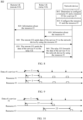
- the network device may alternatively jointly configure the resource #2 and the resource #3 for the service #1, and the network device sends the resource #2 and the resource #3 to the remote UE.
- the remote UE sends the data of the service #1 to the relay UE by using the resource #2, so that the relay UE forwards the data of the service #1 to the network device.
- the remote UE directly sends the data of the service #1 to the network device by using the resource #3.
- the remote UE sends the data to the network device via the relay UE. It may be understood that the solution in this embodiment of this application may also be applied to a multi-hop relay scenario. For example, the remote UE sends the data to the network device via a plurality of relay UEs.
- this embodiment of this application mainly describes a solution related to a transmission resource of uplink data.
- This embodiment of this application is not limited thereto.
- the downlink service for example, a periodically transmitted downlink service
- the downlink service may be configured to be split and carried, or a PDCP duplication function may be enabled.
- the network device separately configures downlink SPS resources for the remote UE and the relay UE, and separately sends data of the service to the remote UE and the relay UE by using the downlink SPSs.
- a periodicity feature of the SPS resource refer to the foregoing descriptions, for example, the relationship shown in FIG. 9 or FIG. 10 .
- transmitting a service for example, sending the service, or for another example, receiving the service
- transmitting the service may also be replaced with transmitting data of the service.
- methods and operations implemented by a device may alternatively be implemented by a component (for example, a chip or a circuit) of a device.
- an embodiment of this application further provides a corresponding apparatus.
- the apparatus includes a corresponding module configured to perform the foregoing method embodiments.
- the module may be software, hardware, or a combination of software and hardware. It may be understood that the technical features described in the foregoing method embodiments are also applicable to the following apparatus embodiments.
- FIG. 15 is a diagram of a data transmission apparatus 1500 according to an embodiment of this application.
- the apparatus 1500 includes a transceiver unit 1510 and a processing unit 1520.
- the transceiver unit 1510 may be configured to implement a corresponding communication function.
- the transceiver unit 1510 may also be referred to as a communication interface or a communication unit.
- the processing unit 1520 may be configured to implement a corresponding processing function, for example, configure a resource.
- the apparatus 1500 further includes a storage unit.
- the storage unit may be configured to store instructions and/or data.
- the processing unit 1520 may read the instructions and/or the data in the storage unit, so that the apparatus implements actions of a device or a network element in the foregoing method embodiments.
- the apparatus 1500 may be the network device in the foregoing embodiments, or may be a component (for example, a chip) of the network device.
- the apparatus 1500 may implement steps or procedures performed by the network device in the foregoing method embodiments.
- the transceiver unit 1510 may be configured to perform receiving/sending-related operations of the network device in the foregoing method embodiments.
- the processing unit 1520 may be configured to perform processing-related operations of the network device in the foregoing method embodiments.
- the transceiver unit 1510 is configured to send information about a first resource to a first terminal device, where the information about the first resource indicates that the first resource is used to transmit a first service of the first terminal device, and the first resource is used to transmit the first service between the first terminal device and a second terminal device.
- the transceiver unit 1510 is further configured to send information about a second resource to the second terminal device, where the information about the second resource indicates that the second resource is used to transmit the first service, and the second resource is used to transmit the first service between the network device and the second terminal device.
- the transceiver unit 1510 is further configured to receive the first service from the first terminal device via the second terminal device.
- the processing unit 1520 is configured to configure the first resource and the second resource.
- the first service has a first correspondence with the first resource.
- the first correspondence is a correspondence between a quality of service QoS flow corresponding to the first service and a first logical channel.
- the first logical channel is a logical channel using the first resource.
- the first logical channel is a corresponding logical channel for transmitting data of the first service between the first terminal device and the second terminal device.
- the transceiver unit 1510 is further configured to send the first correspondence to the first terminal device.
- that the information about the first resource indicates that the first resource is used to transmit the first service includes:
- the information about the first resource indicates that the first logical channel uses the first resource.
- the first logical channel is the corresponding logical channel for transmitting the data of the first service between the first terminal device and the second terminal device.
- the first service has a second correspondence with the second resource.
- the second correspondence is a correspondence between a data radio bearer corresponding to the first service and a second logical channel.
- the second logical channel is a logical channel using the second resource.
- the second logical channel is a corresponding logical channel for transmitting the data of the first service between the second terminal device and the network device.
- the transceiver unit 1510 is further configured to send the second correspondence to the second terminal device.
- that the information about the second resource indicates that the second resource is used to transmit the first service includes:
- the information about the second resource indicates that the second logical channel uses the second resource.
- the second logical channel is the corresponding logical channel for transmitting the data of the first service between the second terminal device and the network device.
- the transceiver unit 1510 is further configured to send information about a third resource to the first terminal device, where the information about the third resource indicates that the third resource is used to transmit the first service.
- the first service has a third correspondence with the third resource.
- the third correspondence is a correspondence between the quality of service QoS flow corresponding to the first service and a third logical channel.
- the third logical channel is a logical channel using the third resource.
- the third logical channel is a corresponding logical channel for transmitting the data of the first service between the first terminal device and the network device.
- the transceiver unit 1510 is further configured to send the third correspondence to the first terminal device.
- that the information about the third resource indicates that the third resource is used to transmit the first service includes:
- the information about the third resource indicates that the third logical channel uses the third resource.
- the third logical channel is the corresponding logical channel for transmitting the data of the first service between the first terminal device and the network device.
- a periodicity of the second resource is the same as a periodicity of the first resource, or a periodicity of the second resource is in an integer multiple relationship with a periodicity of the first resource.
- the first service is a periodically transmitted service.
- the periodicity of the second resource and/or the periodicity of the first resource are/is the same as a periodicity of the first service, or the periodicity of the second resource and/or the periodicity of the first resource are/is an integer multiple of a periodicity of the first service.
- the first service is a periodically transmitted service.
- a periodicity of the third resource satisfies at least one of the following: The periodicity of the third resource is the same as a periodicity of the first resource, or the periodicity of the third resource is in an integer multiple relationship with a periodicity of the first resource; the periodicity of the third resource is the same as a periodicity of the second resource, or the periodicity of the third resource is in an integer multiple relationship with a periodicity of the second resource; or the periodicity of the third resource is the same as a periodicity of the first service, or the periodicity of the third resource is an integer multiple of a periodicity of the first service.
- a time domain start position of the second resource is after a time domain start position of the first resource.
- a time gap between the time domain start position of the second resource and the time domain start position of the first resource is t time units, and t is an integer greater than or equal to 1.
- the apparatus 1500 may be the terminal device (for example, the first terminal device and the second terminal device in FIG. 5 , or for another example, the remote UE and the relay UE in FIG. 6 , FIG. 8 , and FIG. 13 ) in the foregoing embodiments, or may be a component (for example, a chip) of the terminal device.
- the apparatus 1500 may implement steps or procedures performed by the terminal device in the foregoing method embodiments.
- the transceiver unit 1510 may be configured to perform receiving/sending-related operations of the terminal device in the foregoing method embodiments.
- the processing unit 1520 may be configured to perform processing-related operations of the terminal device in the foregoing method embodiments.
- the transceiver unit 1510 is configured to receive information about a first resource from a network device, where the information about the first resource indicates that the first resource is used to transmit a first service of the first terminal device, and the first resource is used to transmit the first service between the first terminal device and the second terminal device.
- the transceiver unit 1510 is further configured to receive information about a second resource from the network device, where the information about the second resource indicates that the second resource is used to transmit the first service, and the second resource is used to transmit the first service between the network device and the second terminal device.
- the transceiver unit 1510 is further configured to send the first service to the second terminal device by using the first resource.
- the transceiver unit 1510 is further configured to receive the first service, and send the first service to the network device by using the second resource.
- the first service has a first correspondence with the first resource.
- the first correspondence is a correspondence between a quality of service QoS flow corresponding to the first service and a first logical channel.
- the first logical channel is a logical channel using the first resource.
- the first logical channel is a corresponding logical channel for transmitting data of the first service between the first terminal device and the second terminal device.
- the transceiver unit 1510 is further configured to receive the first correspondence from the network device.
- that the information about the first resource indicates that the first resource is used to transmit the first service includes:
- the information about the first resource indicates that the first logical channel uses the first resource.
- the first logical channel is the corresponding logical channel for transmitting the data of the first service between the first terminal device and the second terminal device.
- the first service has a second correspondence with the second resource.
- the second correspondence is a correspondence between a data radio bearer corresponding to the first service and a second logical channel.
- the second logical channel is a logical channel using the second resource.
- the second logical channel is a corresponding logical channel for transmitting the data of the first service between the second terminal device and the network device.
- the transceiver unit 1510 is further configured to receive the second correspondence from the network device.
- that the information about the second resource indicates that the second resource is used to transmit the first service includes:
- the information about the second resource indicates that the second logical channel uses the second resource.
- the second logical channel is the corresponding logical channel for transmitting the data of the first service between the second terminal device and the network device.
- the transceiver unit 1510 is further configured to: receive information about a third resource from the network device, where the information about the third resource indicates that the third resource is used to transmit the first service; and send the first service to the network device by using the third resource.
- the first service has a third correspondence with the third resource.
- the third correspondence is a correspondence between the quality of service QoS flow corresponding to the first service and a third logical channel.
- the third logical channel is a logical channel using the third resource.
- the third logical channel is a corresponding logical channel for transmitting the data of the first service between the first terminal device and the network device.
- the transceiver unit 1510 is further configured to receive the third correspondence from the network device.
- that the information about the third resource indicates that the third resource is used to transmit the first service includes:
- the information about the third resource indicates that the third logical channel uses the third resource.
- the third logical channel is the corresponding logical channel for transmitting the data of the first service between the first terminal device and the network device.
- a periodicity of the second resource is the same as a periodicity of the first resource, or a periodicity of the second resource is in an integer multiple relationship with a periodicity of the first resource.
- the first service is a periodically transmitted service.
- the periodicity of the second resource and/or the periodicity of the first resource are/is the same as a periodicity of the first service, or the periodicity of the second resource and/or the periodicity of the first resource are/is an integer multiple of a periodicity of the first service.
- the first service is a periodically transmitted service.
- a periodicity of the third resource satisfies at least one of the following: The periodicity of the third resource is the same as a periodicity of the first resource, or the periodicity of the third resource is in an integer multiple relationship with a periodicity of the first resource; the periodicity of the third resource is the same as a periodicity of the second resource, or the periodicity of the third resource is in an integer multiple relationship with a periodicity of the second resource; or the periodicity of the third resource is the same as a periodicity of the first service, or the periodicity of the third resource is an integer multiple of a periodicity of the first service.
- a time domain start position of the second resource is after a time domain start position of the first resource.
- a time gap between the time domain start position of the second resource and the time domain start position of the first resource is t time units, and t is an integer greater than or equal to 1.
- the apparatus 1500 herein is embodied in a form of a functional unit.
- the term "unit" herein may be an application-specific integrated circuit (application-specific integrated circuit, ASIC), an electronic circuit, a processor (for example, a shared processor, a dedicated processor, or a group processor) configured to execute one or more software or firmware programs, a memory, a combinational logic circuit, and/or another suitable component that supports the described functions.
- ASIC application-specific integrated circuit
- ASIC application-specific integrated circuit
- a processor for example, a shared processor, a dedicated processor, or a group processor
- the apparatus 1500 may be specifically the network device in the foregoing embodiments, and may be configured to perform procedures and/or steps corresponding to the network device in the foregoing method embodiments.
- the apparatus 1500 may be specifically the terminal device in the foregoing embodiments, and may be configured to perform procedures and/or steps corresponding to the terminal device in the foregoing method embodiments. To avoid repetition, details are not described herein again.
- the apparatus 1500 in the foregoing solutions has a function of implementing corresponding steps performed by a device (for example, the network device, or for another example, the terminal device) in the foregoing methods.
- the function may be implemented by hardware, or may be implemented by hardware executing corresponding software.
- the hardware or the software includes one or more modules corresponding to the foregoing function.
- the transceiver unit may be replaced with a transceiver (for example, a sending unit in the transceiver unit may be replaced with a transmitter, and a receiving unit in the transceiver unit may be replaced with a receiver), and another unit, for example, the processing unit, may be replaced with a processor, to separately perform a sending and receiving operation and a related processing operation in the method embodiments.
- the transceiver unit 1510 may alternatively be a transceiver circuit (for example, may include a receiving circuit and a sending circuit), and the processing unit may be a processing circuit.
- the apparatus in FIG. 15 may be a network element or a device in the foregoing embodiments, or may be a chip or a chip system, for example, a system on chip (system on chip, SoC).
- the transceiver unit may be an input/output circuit or a communication interface.
- the processing unit is a processor, a microprocessor, or an integrated circuit integrated on the chip. This is not limited herein.
- FIG. 16 is a diagram of another data transmission apparatus 1600 according to an embodiment of this application.
- the apparatus 1600 includes a processor 1610.
- the processor 1610 is configured to execute a computer program or instructions stored in a memory 1620, or read data/signaling stored in a memory 1620, to perform the methods in the foregoing method embodiments.
- the apparatus 1600 further includes the memory 1620.
- the memory 1620 is configured to store the computer program or the instructions and/or the data.
- the memory 1620 and the processor 1610 may be integrated, or may be disposed separately.
- the apparatus 1600 further includes a transceiver 1630.
- the transceiver 1630 is configured to receive and/or send a signal.
- the processor 1610 is configured to control the transceiver 1630 to receive and/or send the signal.
- the apparatus 1600 is configured to implement operations performed by the network device in the foregoing method embodiments.
- the processor 1610 is configured to execute the computer program or the instructions stored in the memory 1620, to implement related operations of the network device in the foregoing method embodiments.
- the apparatus 1600 is configured to implement operations performed by the terminal device in the foregoing method embodiments.
- the processor 1610 is configured to execute the computer program or the instructions stored in the memory 1620, to implement related operations of the terminal device in the foregoing method embodiments, for example, the method performed by the first terminal device and the second terminal device in the embodiment shown in FIG. 5 , or the method performed by the remote UE and the relay UE in any one of the embodiments shown in FIG. 6 , FIG. 8 , and FIG. 13 .
- processors mentioned in embodiments of this application may be a central processing unit (central processing unit, CPU), or may be another general-purpose processor, a digital signal processor (digital signal processor, DSP), an application-specific integrated circuit (application-specific integrated circuit, ASIC), a field programmable gate array (field programmable gate array, FPGA) or another programmable logic device, a discrete gate or a transistor logic device, a discrete hardware component, or the like.
- the general-purpose processor may be a microprocessor, or the processor may be a conventional processor or the like.
- the memory mentioned in embodiments of this application may be a volatile memory and/or a non-volatile memory.
- the non-volatile memory may be a read-only memory (read-only memory, ROM), a programmable read-only memory (programmable ROM, PROM), an erasable programmable read-only memory (erasable PROM, EPROM), an electrically erasable programmable read-only memory (electrically EPROM, EEPROM), or a flash memory.
- the volatile memory may be a random access memory (random access memory, RAM).
- the RAM may be used as an external cache.
- the RAM includes a plurality of forms below: a static random access memory (static RAM, SRAM), a dynamic random access memory (dynamic RAM, DRAM), a synchronous dynamic random access memory (synchronous DRAM, SDRAM), a double data rate synchronous dynamic random access memory (double data rate SDRAM, DDR SDRAM), an enhanced synchronous dynamic random access memory (enhanced SDRAM, ESDRAM), a synchronous link dynamic random access memory (synchlink DRAM, SLDRAM), and a direct rambus random access memory (direct rambus RAM, DR RAM).
- static random access memory static random access memory
- DRAM dynamic random access memory
- DRAM synchronous dynamic random access memory
- SDRAM double data rate synchronous dynamic random access memory
- double data rate SDRAM double data rate SDRAM
- ESDRAM enhanced synchronous dynamic random access memory
- SLDRAM synchronous link dynamic random access memory
- direct rambus RAM direct rambus RAM
- the processor is a general-purpose processor, a DSP, an ASIC, an FPGA or another programmable logic device, a discrete gate or a transistor logic device, or a discrete hardware component
- the memory storage module
- memory described herein is intended to include but is not limited to these and any other appropriate type of memory.
- the logic circuit 1710 may be a processing circuit in the chip system 1700.
- the logic circuit 1710 may be coupled and connected to a storage unit, and invoke instructions in the storage unit, so that the chip system 1700 can implement the methods and functions in embodiments of this application.
- the input/output interface 1720 may be an input/output circuit in the chip system 1700, and outputs information processed by the chip system 1700, or inputs to-be-processed data or signaling information to the chip system 1700 for processing.
- the logic circuit 1710 is coupled to the input/output interface 1720, and the logic circuit 1710 may send a resource through the input/output interface 1720, where the resource may be configured by the logic circuit 1710; or the input/output interface 1720 may input related information of a service #1 to the logic circuit 1710 for processing.
- the logic circuit 1710 is coupled to the input/output interface 1720, and the logic circuit 1710 may send data through the input/output interface 1720, where the data may be generated by the logic circuit 1710.
- the chip system 1700 is configured to implement operations performed by the network device in the foregoing method embodiments.
- the logic circuit 1710 is configured to implement processing-related operations performed by the network device in the foregoing method embodiments
- the input/output interface 1720 is configured to implement sending and/or receiving-related operations performed by the network device in the foregoing method embodiments.
- the chip system 1700 is configured to implement operations performed by the terminal device in the foregoing method embodiments.
- the logic circuit 1710 is configured to implement processing-related operations performed by the terminal device in the foregoing method embodiments, for example, processing-related operations performed by the first terminal device and the second terminal device in the embodiment shown in FIG. 5 , or processing-related operations performed by the remote UE and the relay UE in any one of the embodiments shown in FIG. 6 , FIG. 8 , and FIG. 13 .
- the input/output interface 1720 is configured to implement sending and/or receiving-related operations performed by the terminal device in the foregoing method embodiments, for example, sending and/or receiving-related operations performed by the first terminal device and the second terminal device in the embodiment shown in FIG. 5 , or sending and/or receiving-related operations performed by the remote UE and the relay UE in any one of the embodiments shown in FIG. 6 , FIG. 8 , and FIG. 13 .
- An embodiment of this application further provides a computer-readable storage medium.
- the computer-readable storage medium stores computer instructions for implementing the methods performed by a device in the foregoing method embodiments.
- the computer when a computer program is executed by a computer, the computer is enabled to implement the method performed by the network device in the foregoing method embodiments.
- the computer when a computer program is executed by a computer, the computer is enabled to implement the method performed by the terminal device in the foregoing method embodiments.
- An embodiment of this application further provides a computer program product, including instructions.
- the instructions are executed by a computer, the method performed by a device (for example, the terminal device, or for another example, the network device) in the foregoing method embodiments is implemented.
- An embodiment of this application further provides a communication system, including the foregoing terminal device and network device.
- the system further includes a device that communicates with the foregoing terminal device and/or network device.
- the disclosed apparatus and method may be implemented in other manners.
- the described apparatus embodiment is merely an example.
- division into the units is merely logical function division and may be other division in actual implementation.
- a plurality of units or components may be combined or integrated into another system, or some features may be ignored or not performed.
- the displayed or discussed mutual couplings or direct couplings or communication connections may be implemented through some interfaces.
- the indirect couplings or communication connections between the apparatuses or units may be implemented in electrical, mechanical, or other forms.
- All or some of the foregoing embodiments may be implemented by software, hardware, firmware, or any combination thereof.
- software is used to implement the embodiments, all or a part of the embodiments may be implemented in a form of a computer program product.
- the computer program product includes one or more computer instructions.
- the computer program instructions When the computer program instructions are loaded and executed on a computer, the procedure or functions according to embodiments of this application are all or partially generated.
- the computer may be a general-purpose computer, a dedicated computer, a computer network, or another programmable apparatus.
- the computer may be a personal computer, a server, or a network device.
- the computer instructions may be stored in a computer-readable storage medium, or may be transmitted from a computer-readable storage medium to another computer-readable storage medium.
- the computer instructions may be transmitted from a website, computer, server, or data center to another website, computer, server, or data center in a wired (for example, a coaxial cable, an optical fiber, or a digital subscriber line (DSL)) or wireless (for example, infrared, radio, or microwave) manner.
- the computer-readable storage medium may be a usable medium accessible by the computer, or a data storage device, for example, a server or a data center, integrating one or more usable media.
- the usable medium may be a magnetic medium (for example, a floppy disk, a hard disk, or a magnetic tape), an optical medium (for example, a DVD), a semiconductor medium (for example, a solid state disk (solid state disk, SSD)), or the like.
- the usable medium may include but is not limited to any medium that can store program code, for example, a USB flash drive, a removable hard disk, a read-only memory (read-only memory, ROM), a random access memory (random access memory, RAM), a magnetic disk, or an optical disc.
Landscapes
- Engineering & Computer Science (AREA)
- Computer Networks & Wireless Communication (AREA)
- Signal Processing (AREA)
- Quality & Reliability (AREA)
- Mobile Radio Communication Systems (AREA)
Applications Claiming Priority (2)
| Application Number | Priority Date | Filing Date | Title |
|---|---|---|---|
| CN202210621531.7A CN117241397A (zh) | 2022-06-02 | 2022-06-02 | 数据传输的方法、装置和系统 |
| PCT/CN2023/096843 WO2023231965A1 (zh) | 2022-06-02 | 2023-05-29 | 数据传输的方法、装置和系统 |
Publications (2)
| Publication Number | Publication Date |
|---|---|
| EP4529318A1 true EP4529318A1 (de) | 2025-03-26 |
| EP4529318A4 EP4529318A4 (de) | 2025-10-08 |
Family
ID=89026913
Family Applications (1)
| Application Number | Title | Priority Date | Filing Date |
|---|---|---|---|
| EP23815145.0A Pending EP4529318A4 (de) | 2022-06-02 | 2023-05-29 | Datenübertragungsverfahren, -vorrichtung und -system |
Country Status (4)
| Country | Link |
|---|---|
| US (1) | US20250097965A1 (de) |
| EP (1) | EP4529318A4 (de) |
| CN (1) | CN117241397A (de) |
| WO (1) | WO2023231965A1 (de) |
Families Citing this family (1)
| Publication number | Priority date | Publication date | Assignee | Title |
|---|---|---|---|---|
| CN121771306A (zh) * | 2024-09-29 | 2026-03-31 | 华为技术有限公司 | 数据传输方法、通信装置及存储介质 |
Family Cites Families (9)
| Publication number | Priority date | Publication date | Assignee | Title |
|---|---|---|---|---|
| MX2019015687A (es) * | 2017-09-25 | 2020-02-26 | Guangdong Oppo Mobile Telecommunications Corp Ltd | Metodo de configuracion de recursos, dispositivo terminal y dispositivo de red. |
| EP3858018A4 (de) * | 2018-09-30 | 2022-06-22 | Telefonaktiebolaget LM Ericsson (publ) | Verfahren und vorrichtung zur selbstgesteuerten uplink-übertragung |
| EP3917236B1 (de) * | 2019-05-10 | 2024-05-08 | Guangdong Oppo Mobile Telecommunications Corp., Ltd. | Datenübertragungsverfahren, endgerätevorrichtung und netzwerkvorrichtung |
| CN112311511B (zh) * | 2019-07-26 | 2023-06-06 | 华为技术有限公司 | 数据传输方法和装置 |
| CN112449422B (zh) * | 2019-08-29 | 2025-02-07 | 华为技术有限公司 | 上行传输方法及通信装置 |
| CN112689334B (zh) * | 2019-10-18 | 2023-12-19 | 华为技术有限公司 | 一种数据传输方法、装置及相关设备 |
| WO2021081951A1 (zh) * | 2019-10-31 | 2021-05-06 | 华为技术有限公司 | 上行传输方法及通信装置 |
| CN121418946A (zh) * | 2020-02-13 | 2026-01-27 | 中兴通讯股份有限公司 | sidelink中继通信方法、通信设备及存储介质 |
| CN113573422B (zh) * | 2020-04-28 | 2023-10-20 | 维沃移动通信有限公司 | 远端终端的连接管理方法、终端及网络侧设备 |
-
2022
- 2022-06-02 CN CN202210621531.7A patent/CN117241397A/zh active Pending
-
2023
- 2023-05-29 WO PCT/CN2023/096843 patent/WO2023231965A1/zh not_active Ceased
- 2023-05-29 EP EP23815145.0A patent/EP4529318A4/de active Pending
-
2024
- 2024-12-02 US US18/965,558 patent/US20250097965A1/en active Pending
Also Published As
| Publication number | Publication date |
|---|---|
| US20250097965A1 (en) | 2025-03-20 |
| EP4529318A4 (de) | 2025-10-08 |
| WO2023231965A1 (zh) | 2023-12-07 |
| CN117241397A (zh) | 2023-12-15 |
Similar Documents
| Publication | Publication Date | Title |
|---|---|---|
| US11399361B2 (en) | V2X sidelink communication | |
| EP3634071B1 (de) | Auswahl der kanalzugriffsprioritätsklasse | |
| US20220225341A1 (en) | Communication Method and Apparatus | |
| KR102036778B1 (ko) | 무선 통신 시스템에서의 d2d 데이터 전송 방법 및 장치 | |
| CN115413045B (zh) | 信息传输方法、终端设备和网络设备 | |
| WO2017024659A1 (zh) | 无线通信系统中的电子设备和无线通信方法 | |
| EP4535897A1 (de) | Datenübertragungsverfahren, -vorrichtung und -system | |
| EP4322593A1 (de) | Kommunikationsverfahren und -vorrichtung | |
| WO2023216986A1 (zh) | 缓存状态报告bsr指示方法和装置 | |
| CN116210314B (zh) | 无线通信方法、终端设备和网络设备 | |
| US20250097965A1 (en) | Data transmission method, apparatus, and system | |
| US12604333B2 (en) | Relay operations in wireless communication | |
| US20240163020A1 (en) | Communication method and storage medium | |
| US20240244476A1 (en) | Wireless communication method, and devices | |
| US20250008535A1 (en) | Communication apparatus and communication method for allocating one or more additional operating windows for a sidelink signal | |
| WO2023060404A1 (zh) | 逻辑信道优先级排序方法、装置、设备及存储介质 | |
| US20250351161A1 (en) | Data transmission method and communication apparatus | |
| US20250220706A1 (en) | Sidelink communication method and terminal device | |
| WO2025167766A1 (zh) | 通信方法和通信装置 | |
| WO2026045923A1 (zh) | 一种通信方法及相关装置 | |
| WO2024067869A1 (zh) | 通信方法和通信装置 | |
| CN119729857A (zh) | 用于侧行通信的方法以及通信设备 | |
| WO2023193243A1 (zh) | 通信方法、终端设备、网络设备和通信装置 | |
| CN120390263A (zh) | 一种通信方法及装置 |
Legal Events
| Date | Code | Title | Description |
|---|---|---|---|
| STAA | Information on the status of an ep patent application or granted ep patent |
Free format text: STATUS: THE INTERNATIONAL PUBLICATION HAS BEEN MADE |
|
| PUAI | Public reference made under article 153(3) epc to a published international application that has entered the european phase |
Free format text: ORIGINAL CODE: 0009012 |
|
| STAA | Information on the status of an ep patent application or granted ep patent |
Free format text: STATUS: REQUEST FOR EXAMINATION WAS MADE |
|
| 17P | Request for examination filed |
Effective date: 20241216 |
|
| AK | Designated contracting states |
Kind code of ref document: A1 Designated state(s): AL AT BE BG CH CY CZ DE DK EE ES FI FR GB GR HR HU IE IS IT LI LT LU LV MC ME MK MT NL NO PL PT RO RS SE SI SK SM TR |
|
| DAV | Request for validation of the european patent (deleted) | ||
| DAX | Request for extension of the european patent (deleted) | ||
| A4 | Supplementary search report drawn up and despatched |
Effective date: 20250909 |
|
| RIC1 | Information provided on ipc code assigned before grant |
Ipc: H04W 72/04 20230101AFI20250903BHEP Ipc: H04W 72/20 20230101ALI20250903BHEP Ipc: H04W 72/23 20230101ALI20250903BHEP Ipc: H04W 72/40 20230101ALI20250903BHEP Ipc: H04W 72/54 20230101ALI20250903BHEP Ipc: H04W 88/04 20090101ALI20250903BHEP Ipc: H04W 92/18 20090101ALN20250903BHEP |