EP4529316A1 - Pmi-parameter-feedbackverfahren für gemeinsame multi-trp-übertragung, vorrichtung, endgerät und netzwerkseitige vorrichtung - Google Patents
Pmi-parameter-feedbackverfahren für gemeinsame multi-trp-übertragung, vorrichtung, endgerät und netzwerkseitige vorrichtung Download PDFInfo
- Publication number
- EP4529316A1 EP4529316A1 EP23807043.7A EP23807043A EP4529316A1 EP 4529316 A1 EP4529316 A1 EP 4529316A1 EP 23807043 A EP23807043 A EP 23807043A EP 4529316 A1 EP4529316 A1 EP 4529316A1
- Authority
- EP
- European Patent Office
- Prior art keywords
- reference signal
- target
- domain information
- pmi
- csi
- Prior art date
- Legal status (The legal status is an assumption and is not a legal conclusion. Google has not performed a legal analysis and makes no representation as to the accuracy of the status listed.)
- Pending
Links
Images



Classifications
-
- H—ELECTRICITY
- H04—ELECTRIC COMMUNICATION TECHNIQUE
- H04B—TRANSMISSION
- H04B7/00—Radio transmission systems, i.e. using radiation field
- H04B7/02—Diversity systems; Multi-antenna system, i.e. transmission or reception using multiple antennas
- H04B7/04—Diversity systems; Multi-antenna system, i.e. transmission or reception using multiple antennas using two or more spaced independent antennas
- H04B7/0413—MIMO systems
- H04B7/0456—Selection of precoding matrices or codebooks, e.g. using matrices antenna weighting
-
- H—ELECTRICITY
- H04—ELECTRIC COMMUNICATION TECHNIQUE
- H04B—TRANSMISSION
- H04B7/00—Radio transmission systems, i.e. using radiation field
- H04B7/02—Diversity systems; Multi-antenna system, i.e. transmission or reception using multiple antennas
- H04B7/022—Site diversity; Macro-diversity
- H04B7/024—Co-operative use of antennas of several sites, e.g. in co-ordinated multipoint or co-operative multiple-input multiple-output [MIMO] systems
-
- H—ELECTRICITY
- H04—ELECTRIC COMMUNICATION TECHNIQUE
- H04B—TRANSMISSION
- H04B7/00—Radio transmission systems, i.e. using radiation field
- H04B7/02—Diversity systems; Multi-antenna system, i.e. transmission or reception using multiple antennas
- H04B7/04—Diversity systems; Multi-antenna system, i.e. transmission or reception using multiple antennas using two or more spaced independent antennas
- H04B7/0413—MIMO systems
- H04B7/0417—Feedback systems
- H04B7/0421—Feedback systems utilizing implicit feedback, e.g. steered pilot signals
-
- H—ELECTRICITY
- H04—ELECTRIC COMMUNICATION TECHNIQUE
- H04B—TRANSMISSION
- H04B7/00—Radio transmission systems, i.e. using radiation field
- H04B7/02—Diversity systems; Multi-antenna system, i.e. transmission or reception using multiple antennas
- H04B7/04—Diversity systems; Multi-antenna system, i.e. transmission or reception using multiple antennas using two or more spaced independent antennas
- H04B7/06—Diversity systems; Multi-antenna system, i.e. transmission or reception using multiple antennas using two or more spaced independent antennas at the transmitting station
- H04B7/0613—Diversity systems; Multi-antenna system, i.e. transmission or reception using multiple antennas using two or more spaced independent antennas at the transmitting station using simultaneous transmission
- H04B7/0615—Diversity systems; Multi-antenna system, i.e. transmission or reception using multiple antennas using two or more spaced independent antennas at the transmitting station using simultaneous transmission of weighted versions of same signal
- H04B7/0619—Diversity systems; Multi-antenna system, i.e. transmission or reception using multiple antennas using two or more spaced independent antennas at the transmitting station using simultaneous transmission of weighted versions of same signal using feedback from receiving side
- H04B7/0621—Feedback content
- H04B7/063—Parameters other than those covered in groups H04B7/0623 - H04B7/0634, e.g. channel matrix rank or transmit mode selection
-
- H—ELECTRICITY
- H04—ELECTRIC COMMUNICATION TECHNIQUE
- H04B—TRANSMISSION
- H04B7/00—Radio transmission systems, i.e. using radiation field
- H04B7/02—Diversity systems; Multi-antenna system, i.e. transmission or reception using multiple antennas
- H04B7/04—Diversity systems; Multi-antenna system, i.e. transmission or reception using multiple antennas using two or more spaced independent antennas
- H04B7/06—Diversity systems; Multi-antenna system, i.e. transmission or reception using multiple antennas using two or more spaced independent antennas at the transmitting station
- H04B7/0613—Diversity systems; Multi-antenna system, i.e. transmission or reception using multiple antennas using two or more spaced independent antennas at the transmitting station using simultaneous transmission
- H04B7/0615—Diversity systems; Multi-antenna system, i.e. transmission or reception using multiple antennas using two or more spaced independent antennas at the transmitting station using simultaneous transmission of weighted versions of same signal
- H04B7/0619—Diversity systems; Multi-antenna system, i.e. transmission or reception using multiple antennas using two or more spaced independent antennas at the transmitting station using simultaneous transmission of weighted versions of same signal using feedback from receiving side
- H04B7/0636—Feedback format
- H04B7/0639—Using selective indices, e.g. of a codebook, e.g. pre-distortion matrix index [PMI] or for beam selection
-
- H—ELECTRICITY
- H04—ELECTRIC COMMUNICATION TECHNIQUE
- H04L—TRANSMISSION OF DIGITAL INFORMATION, e.g. TELEGRAPHIC COMMUNICATION
- H04L5/00—Arrangements affording multiple use of the transmission path
-
- H—ELECTRICITY
- H04—ELECTRIC COMMUNICATION TECHNIQUE
- H04L—TRANSMISSION OF DIGITAL INFORMATION, e.g. TELEGRAPHIC COMMUNICATION
- H04L5/00—Arrangements affording multiple use of the transmission path
- H04L5/003—Arrangements for allocating sub-channels of the transmission path
- H04L5/0032—Distributed allocation, i.e. involving a plurality of allocating devices, each making partial allocation
- H04L5/0035—Resource allocation in a cooperative multipoint environment
-
- H—ELECTRICITY
- H04—ELECTRIC COMMUNICATION TECHNIQUE
- H04L—TRANSMISSION OF DIGITAL INFORMATION, e.g. TELEGRAPHIC COMMUNICATION
- H04L5/00—Arrangements affording multiple use of the transmission path
- H04L5/003—Arrangements for allocating sub-channels of the transmission path
- H04L5/0048—Allocation of pilot signals, i.e. of signals known to the receiver
Definitions
- This application belongs to the technical field of wireless communications, and particularly relates to a PMI parameter feedback method and apparatus for multi-TRP joint transmission, a terminal, and a network side device.
- Coordinated multiple points (Coordinated Multiple Points, CoMP) transmission refers to that multiple geographically separated transmission reception points (Transmission Reception Point, TRPs) are coordinated to transmit data for a terminal or jointly receive data transmitted by a terminal.
- TRPs Transmission Reception Point
- Multiple transmission points participating in cooperation usually refer to base stations in different cells. Multiple cell base stations may cooperate to use an interference signal as a useful signal, thereby reducing the interference between cells and improving the spectrum utilization rate of a system.
- Each common CoMP scheme may be grouped into one of the following categories: joint processing (Joint Processing, JP) or collaborative scheduling (Collaborative Scheduling, CS)/coordinated beamforming (Coordinated Beamforming, CB).
- JP Joint Processing
- CS Collaborative Scheduling
- CB Coordinated Beamforming
- Joint processing refers to data of a terminal (User Equipment) UE being available on more than one time frequency resource point in a CoMP cooperative set, including:
- W f [ f 0 f 1 ... f Mv-1 ] , where f i , i ⁇ ⁇ 0,1, ...,Mr - 1 ⁇ represents a discrete Fourier transform (Discrete Fourier Transform, DFT) vector of dimension 1 ⁇ N 3 .
- DFT Discrete Fourier Transform
- the PMI parameter feedback method in the related art is not applicable to a scenario of multi-TRP cooperative transmission.
- Embodiments of this application provide a PMI parameter feedback method and apparatus for multi-TRP joint transmission, a terminal, and a network side device, which can solve the problem that the PMI parameter feedback method in the related art is not applicable to a scenario of multi-TRP cooperative transmission.
- a PMI parameter feedback method for multi-TRP joint transmission includes: determining, by a terminal according to target information, that one parameter value is fed back for a target PMI parameter corresponding to multiple target reference signals among multiple reference signals, where the multiple reference signals are configured by a network side for determining a PMI parameter for joint transmission, and one of the reference signals is associated with one TRP; and transmitting, by the terminal, a PMI parameter for multi-TRP joint transmission, where for the target PMI parameters of multiple target TRPs associated with the multiple target reference signals, the terminal transmits one parameter value for the target PMI parameters.
- a PMI parameter feedback apparatus for multi-TRP joint transmission including: a first determination module, configured to determine according to target information that one parameter value is fed back for a target PMI parameter corresponding to multiple target reference signals among multiple reference signals, where the multiple reference signals are configured by a network side for determining a PMI parameter for joint transmission, and one of the reference signals is associated with one TRP; and a first transmitting module, configured to transmit a PMI parameter for multi-TRP joint transmission, where for the target PMI parameters of multiple target TRPs associated with the multiple target reference signals, the terminal transmits one parameter value for the target PMI parameters.
- a PMI parameter feedback method for multi-TRP joint transmission including: obtaining, by a terminal, target PMI parameters corresponding to multiple reference signals, where the multiple reference signals are reference signals configured for determining a target PMI parameter for joint transmission, one of the reference signals is associated with one TRP, and the multiple reference signals include a first reference signal and a second reference signal; obtaining, by the terminal, an offset of a first target PMI parameter corresponding to the first reference signal relative to a second target PMI parameter corresponding to the second reference signal; and transmitting, by the terminal, the second target PMI parameter and an offset of the first target PMI parameter relative to the second target PMI parameter.
- a PMI parameter feedback apparatus for multi-TRP joint transmission, including: a first obtaining module, configured to obtain target PMI parameters corresponding to multiple reference signals, where the multiple reference signals are reference signals configured for determining a target PMI parameter for joint transmission, one of the reference signals is associated with one TRP, and the multiple reference signals include a first reference signal and a second reference signal; a second obtaining module, configured to obtain an offset of a first target PMI parameter corresponding to the first reference signal relative to a second target PMI parameter corresponding to the second reference signal; and a second transmitting module, configured to transmit the second target PMI parameter and an offset of the first target PMI parameter relative to the second target PMI parameter.
- a PMI parameter obtaining method for multi-TRP joint transmission including: configuring, by a network side device for a terminal, multiple reference signals for determining a PMI parameter for joint transmission, where one of the reference signals is associated with one TRP; receiving, by the network side device, a PMI parameter for multi-TRP joint transmission transmitted by the terminal; determining, by the network side device according to target information, that one parameter value is fed back for a target PMI parameter corresponding to multiple target reference signals among the multiple reference signals; and obtaining, by the network side device, parameter values of the target PMI parameters from the received PMI parameters, and obtaining parameter values of the target PMI parameters corresponding to the multiple target reference signals according to the parameter values of the target PMI parameters.
- a PMI parameter obtaining apparatus for multi-TRP joint transmission including: a first configuration module, configured to configure for a terminal multiple reference signals for determining a PMI parameter for joint transmission, where one of the reference signals is associated with one TRP; a first receiving module, configured to receive a PMI parameter for multi-TRP joint transmission transmitted by the terminal; a second determination module, configured to determine according to target information that one parameter value is fed back for a target PMI parameter corresponding to multiple target reference signals among the multiple reference signals; and a third obtaining module, configured to obtain parameter values of the target PMI parameters from the received PMI parameters, and obtain parameter values of the target PMI parameters corresponding to the multiple target reference signals according to the parameter values of the target PMI parameters.
- a PMI parameter obtaining method for multi-TRP joint transmission including: configuring, by a network side device for a terminal, multiple reference signals for determining a PMI parameter for joint transmission, where one of the reference signals is associated with one TRP, and the multiple reference signals include a first reference signal and a second reference signal; receiving, by the network side device from the terminal, a second target PMI parameter corresponding to the second reference signal and an offset of a first target PMI parameter corresponding to the first reference signal relative to the second target PMI parameter; and obtaining, by the network side device, the second target PMI parameter corresponding to the second reference signal and the first target PMI parameter corresponding to the first reference signal according to the second target PMI parameter and the offset of the first target PMI parameter relative to the second target PMI parameter.
- a PMI parameter obtaining apparatus for multi-TRP joint transmission including: a second configuration module, configured to configure for a terminal multiple reference signals for determining a PMI parameter for joint transmission, where one of the reference signals is associated with one TRP, and the multiple reference signals include a first reference signal and a second reference signal; a second receiving module, configured to receive from the terminal a second target PMI parameter corresponding to the second reference signal and an offset of a first target PMI parameter corresponding to the first reference signal relative to the second target PMI parameter; and a fourth obtaining module, configured to obtain the second target PMI parameter corresponding to the second reference signal and the first target PMI parameter corresponding to the first reference signal according to the second target PMI parameter and the offset of the first target PMI parameter relative to the second target PMI parameter.
- a terminal includes a processor and a memory.
- the memory stores programs or instructions executable on the processor.
- the programs or instructions when executed by the processor, implement the steps of the method according to the first aspect or implement the steps of the method according to the third aspect.
- a terminal including a processor and a communication interface.
- the processor is configured to implement the steps of the method according to the first aspect or implement the steps of the method according to the third aspect.
- the communication interface is configured to communicate with an external device.
- the network side device includes a processor and a memory.
- the memory stores programs or instructions executable on the processor.
- the programs or instructions when executed by the processor, implement the steps of the method according to the fifth aspect or implement the steps of the method according to the seventh aspect.
- a network side device including a processor and a communication interface.
- the processor is configured to implement the steps of the method according to the fifth aspect or implement the steps of the method according to the seventh aspect.
- the communication interface is configured to communicate with an external device.
- a PMI parameter obtaining system for multi-TRP joint transmission including: a terminal and a network side device, where the terminal may be configured to execute the steps of the method as described in the first aspect or execute the steps of the method as described in the third aspect, and the network side device may be configured to execute the steps of the method as described in the fifth aspect or execute the steps of the method as described in the seventh aspect.
- a fourteenth aspect there is provided a readable storage medium.
- the readable storage medium stores programs or instructions.
- the programs or instructions when executed by a processor, implement steps of the method as described in the first aspect, implement steps of the method as described in the third aspect, implement steps of the method as described in the fifth aspect, or implement steps of the method as described in the seventh aspect.
- a chip includes a processor and a communication interface.
- the communication interface is coupled to the processor.
- the processor is configured to execute programs or instructions to implement the method as described in the first aspect, or implement the method as described in the third aspect, or implement the method as described in the fifth aspect, or implement the method as described in the seventh aspect.
- a computer program/program product is stored in a storage medium.
- the computer program/program product when executed by at least one processor, implements the steps of the method as described in the first aspect, or implements the method as described in the third aspect, or implements the method as described in the fifth aspect, or implements the method as described in the seventh aspect.
- a terminal determines according to target information that only one parameter value is fed back for a target PMI parameter corresponding to multiple target reference signals among multiple reference signals (i.e., associated multiple TRPs). Then, when transmitting a PMI parameter for multi-TRP joint transmission, the terminal feeds back a parameter value for one of target PMIs corresponding to the multiple target reference signals, so that the PMI parameters may be fed back in a case of multi-TRP joint transmission, and the feedback overheads of the PMI parameters can be reduced.
- first and second in the specification and claims of this application are used to distinguish similar objects, but are unnecessarily used to describe a specific sequence or order. It will be appreciated that the terms used in this way are exchangeable in a proper case, so that embodiments of this application can be implemented in an order different from the order shown or described herein, and objects distinguished by "first” and “second” are usually of the same category and the number of the objects is not defined. For example, there may be one or more first objects.
- “and/or” in the specification and claims represents at least one of connected objects, and the character “/" usually represents that previous and next associated objects form an "or” relationship.
- LTE Long Term Evolution
- LTE-A Long Term Evolution-Advanced
- CDMA code division multiple access
- Time Division Multiple Access Time Division Multiple Access
- FDMA frequency division multiple access
- OFDMA Orthogonal Frequency Division Multiple Access
- SC-FDMA single-carrier Frequency Division Multiple Access
- system and “network” in the embodiments of this application are usually interchangeably used, and the technologies described may be applied to the systems and radio technologies mentioned above, and may also be applied to other systems and radio technologies.
- a new radio (New Radio, NR) system is described in the following description, and the term NR is used in most description below.
- NR New Radio
- these technologies may also be applied to other applications other than the NR system, for example, a 6th generation (6 th Generation, 6G) communication system.
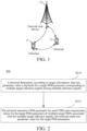
- FIG. 1 shows a block diagram of a wireless communication system to which embodiments of this application may be applied.
- the wireless communication system includes a terminal 11 and a network side device 12.
- the terminal 11 may be a terminal side device such as a mobile phone, a tablet personal computer (Tablet Personal Computer), a laptop computer (Laptop Computer) or a notebook computer, a personal digital assistant (Personal Digital Assistant, PDA), a palmtop computer, a notebook, an ultra-mobile personal computer (ultra-mobile personal computer, UMPC), a mobile Internet device (Mobile Internet Device, MID), an augmented reality (augmented reality, AR)/virtual reality (virtual reality, VR) device, a robot, a wearable device (Wearable Device), vehicle user equipment (Vehicle User Equipment, VUE), pedestrian user equipment (Pedestrian User Equipment, PUE), a smart home (a home device with a wireless communication function, such as a refrigerator, a television, a washer or furniture), a game machine, a personal computer (
- the access network device may include a base station, a wireless local area network (Wireless Local Area Network, WLAN) access point or a Wi-Fi node, etc.
- the base station may be referred to as a node B, an evolved node B (evolved Node B, eNB), an access point, a base transceiver station (Base Transceiver Station, BTS), a radio base station, a radio transceiver, a basic service set (Basic Service Set, BSS), an extended service set (Extended Service Set, ESS), a household node B, a household evolved node B, a transmission reception point (Transmission Reception Point, TRP) or some other appropriate terms in the field provided that the same technical effect is achieved.
- the base station is not limited to specific technical vocabularies. It is to be noted that in embodiments of this application, only a base station in an NR system is described as an example, but the specific type of the base station is not limited.
- a codebook R16 TypeII is designed using a beam combination principle. Considering the problem of PMI feedback overheads, the design of the codebook R16 TypeII increases frequency domain compression, expands the number of supported highest Ranks to 4, and increases the distribution of non-zero coefficients for PMI feedback indicated by a Bitmap mode.
- a mapping rule from k l , p 1 to p l , p 1 is as shown in Table 1.
- i 1,8, l indicates that the strongest beam is a beam corresponding to an i l ⁇ th non-zero coefficient
- rank is greater than 1
- i 1,8, l indicates that the strongest beam is an i l ⁇ th beam.
- N 3 is the number of PMI sub-bands, namely the total number of taps
- Mv represents the number of reserved taps
- n 3 , l f is Mv remapped tap indexes obtained by the UE
- n 3 , l 1 , ... , n 3 , l M ⁇ ⁇ 1 is obtained from i 1,6, l and M initial in the PMI. Only non-zero n 3 , l f is fed back.
- M initial ⁇ ⁇ -2 M v + 1, -2 M v + 2, ...,0 ⁇ may be obtained from i 1,5 (note: layer common):
- the process of obtaining i 1,6, l and n 3 , l f is consistent with the mode of obtaining a W 1 beam sequence number, which is obtained using a combination number.
- n 3 , l f which is greater than M initial + N3 - 1 is mapped to 0,1, ...,2 M v - 1, and then the combination number is calculated.
- the PMI coefficients are i 1 and i 2 , where i 1 includes i 1,1 , i 1,2 , i 1,5 , i 1,6,v , i 1,7,v , and i 1,8,v , and i 2 includes i 2,3,v , i 2,4,v , and i 2,5,v , where v is equal to one or more of 1, 2, 3, and 4.
- v is equal to 1 or 2
- v is equal to 1, 2, 3, or 4
- i 1,1 is used for indicating the sequence number of an orthogonal DFT vector group, which is equal to [ q 1 , q 2 ], where q 1 ⁇ ⁇ 0,1, ..., O 1 - 1 ⁇ , q 2 ⁇ ⁇ 0,1, ..., O 2 - 1 ⁇ , and O 1 , O 2 is an oversampling factor configured by the network.
- i 1,2 is used for indicating the sequence numbers of L vectors within the orthogonal DFT vector group indicated by i 1,1 , and i 1 , 2 ⁇ 0 , 1 , ... , N 1 N 2 L ⁇ 1 , where N 1, N 2 is a port number parameter configured for the network, L is the number of DFT vectors indicated for the network, and N 1 N 2 L represents a combination number in which L beams are selected from N 1 N 2 beams (beam).
- the mapping of the sequence numbers of i 1,2 to L DFT vectors is as shown in Table 3.
- n i is a global sequence number of a DFT vector, which is determined by sequence numbers n 2 i and n 1 i . The value of n i increases as i increases.
- i 1,5 indicates a starting position M initial of a window having a length of 2 M v , and i 1,5 ⁇ ⁇ 0,1, ..., 2 M y - 1 ⁇ , where M v represents the number of time domain taps. Note: it is only possible that N 3 > 19. When N 3 ⁇ 19, i 1,5 is equal to 0, and the terminal does not need to feed back the coefficient.
- i 1,6,v is used for indicating the position of M v tap coefficients fed back by layer (layer) v in N 3 tap coefficients.
- the value is in two cases: when N 3 > 19, i 1,6, v E 0 , 1 , ... , 2 M v ⁇ 1 M v ⁇ 1 ⁇ 1 , and when N 3 ⁇ 19, i 1 , 6 , v ⁇ 0 , 1 , ... , N 3 ⁇ 1 M v ⁇ 1 ⁇ 1 , which may be fed back in the manner of the combination number.
- i 1,7,v is a non-zero coefficient indicator of layer v, which is a bit (bit) sequence having a total length of 2 LM v .
- i 2,3,v is quantization indicators of two polarized amplitude coefficients of layer v.
- Each amplitude coefficient is a 4-bit bit string (bit string), and each codepoint (codepoint) corresponds to a quantization value, where the polarized amplitude coefficient corresponding to the strongest coefficient is not fed back and is assumed to be 1.
- i 2,4,v is quantization indicators of amplitude coefficients of all tap coefficients.
- Each amplitude coefficient is a 3-bit bit string, each codepoint corresponds to a quantization value, and a total of 2 LM v amplitude coefficients are obtained.
- the amplitude coefficient corresponding to the strongest coefficient is not fed back and is assumed to be 1, and only non-zero amplitude coefficients among the remaining coefficients are fed back. Therefore, the number of total feedback coefficients for layer v is K Nz,v - 1, where K Nz,v represents the number of non-zero amplitude coefficients of layer v.
- i 2,5,v is quantization indicators of phase coefficients of all tap coefficients.
- Each phase coefficient is a 4-bit bit string, each codepoint corresponds to a quantization value, and a total of 2 LM v phase coefficients are obtained.
- the phase coefficient corresponding to the strongest coefficient is not fed back and is assumed to be 0, and only phase coefficients corresponding to non-zero amplitude coefficients among the remaining coefficients are fed back. Therefore, the number of total feedback coefficients for layer v is K Nz,v - 1, where K Nz,v represents the number of non-zero amplitude coefficients.
- the bit priority of i 2,4,v , i 2,5,v , and i 1,7,v is determined according to a calculated preferred value of each bit. A higher priority corresponds to a lower preferred value.
- FIG. 2 shows a schematic flowchart of a PMI parameter feedback method for multi-TRP joint transmission according to embodiments of this application.
- the method 200 may be performed by a terminal.
- the method may be performed by software or hardware installed on the terminal.
- the method may include the following steps.
- S210 The terminal determines, according to target information, that one parameter value is fed back for a target PMI parameter corresponding to multiple target reference signals among multiple reference signals.
- the multiple reference signals are configured by a network side for determining a PMI parameter for joint transmission, and one of the reference signals is associated with one TRP.
- a network side device may obtain, for a terminal, multiple reference signals for determining a PMI parameter for joint transmission, where one of the reference signals is associated with one TRP.
- a PMI parameter corresponding to a TRP is obtained through a reference signal.
- the target information may include one of the following:
- the first target high-layer signaling may include at least one of the following:
- the first high-layer signaling, the second high-layer signaling and the third high-layer signaling may be different signaling or may be the same signaling.
- the first target high-layer signaling may be associated with a CSI report configuration (CSI-ReportConfig), and the first target high-layer signaling is configured in one of the following:
- CSI resource set information element Information element, IE
- Non-Zero Power CSI-RS ResourceSet Non-Zero Power CSI-RS ResourceSet, NZP-CSI-RS-ResourceSet
- a space division reference resource Space Division Reference Resource, SD-Reference Resource
- a frequency division reference resource Frequency Division Reference Resource, FD-Reference Resource
- SD-FDReferenceResource space division-frequency division reference resource
- NZP-CSI-RS-Resource multiple non-zero power channel state information resource (Non-Zero Power CSI-RS Resource, NZP-CSI-RS-Resource) groups are configured in the NZP-CSI-RS-ResourceSet, and the terminal may assume that each NZP-CSI-RS-Resource group has the same spatial domain information reference signal and/or frequency domain information reference signal.
- a space division reference resource information (SD-ReferenceResource informal, SD-ReferenceResourceInfo) domain and a frequency division reference resource information (FD-ReferenceResourceInfo) domain are configured, or a space division-frequency division reference resource information (SD-FD-ReferenceResourceInfo) domain is configured, containing an enumeration value, for example, true/false (true/false), used for indicating whether the resource is a spatial domain information and/or frequency domain information reference signal.
- an SD-ReferencePortGroup domain and an FD-ReferencePortGroup domain are configured, or an SD-FD-ReferencePortGroup domain is configured, containing a CSI-RS port group ID, used for indicating a corresponding spatial domain information and/or frequency domain information reference port group.
- an SD-ReferenceResource domain and an FD-ReferenceResource domain are configured, or an SD-FD-ReferenceResource domain is configured, containing a CSI-RS ID, used for indicating a corresponding spatial domain information and/or frequency domain information reference signal.
- the reference signal (i.e., at least one of the spatial domain information reference signal, the frequency domain information reference signal and time domain information reference signal) indicated by the predetermined rule may include one of the following:
- a candidate spatial domain information set includes four orthogonal beam groups, where each group has four beams as shown in Table 8 respectively, and a group of spatial domain information corresponding to reference signals other than the spatial domain information reference signal is selected from the four groups.
- Table 8 Group 1 Group 2 Group 3 Group 4 G8B1, G8B2, G8B3, G8B4 G5B1, G5B2, G5B3, G5B4 G12B1, G12B2, G12B3, G12B4 G9B1, G9B2, G9B3, G9B4
- a sequence length of the non-zero coefficient indicators in the coefficient matrix corresponding to the target reference signals having the same frequency domain information and spatial domain information is: 2*L*M_v, where L is the number of beams corresponding to one reference signal, and M_v is the size of a frequency domain information set at rank v corresponding to one reference signal.
- a non-zero coefficient indicator (i 1,7,l ) of the corresponding coefficient matrix (W2) of reference resources having the same time domain information, frequency domain information and spatial domain information may be identical.
- the terminal only needs to feed back a shared non-zero coefficient indicator.
- the sequence length of the non-zero coefficient indicator may be 2*L*M_v*T_v, where L is the number of beams corresponding to one reference resource, M_v is the size of a delay set at rank v corresponding to one reference source, and T_v is the size of a Doppler set at rank v corresponding to one reference source.
- the terminal may indicate some sharable spatial domain information, frequency domain information or time domain information, thereby preventing the terminal from obtaining the spatial domain information, the frequency domain information and the time domain information for each TRP. Also, only a piece of the shared information needs to be fed back, thereby further reducing the feedback overheads in some scenarios.
- FIG. 3 shows a schematic flowchart of a PMI parameter obtaining method for multi-TRP joint transmission according to embodiments of this application.
- the method 300 may be performed by a network side device.
- the method may be performed by software or hardware installed on the network side device.
- the method mainly includes the following steps.
- a network side device configures for a terminal multiple reference signals for determining a PMI parameter for joint transmission, where one of the reference signals is associated with one TRP.
- the target information includes one of the following:
- the predetermined rule may determine which reference signals are spatial domain information reference signals, which reference signals are frequency domain information reference signals, and which reference signals are time domain information reference signals among the multiple reference signals configured by the network side device for the terminal.
- the network side device may recover parameter values of target PMI parameters corresponding to the multiple target reference signals according to the received PMI parameters, thereby obtaining a PMI parameter for multi-TRP joint transmission.
- the operation that the network side device determines, according to target information, a target PMI parameter fed back by the terminal for multiple target reference signals among the multiple reference signals may include at least one of the following:
- the operation of obtaining, by the network side device, parameter values of the target PMI parameters from the received PMI parameters, and obtaining parameter values of the target PMI parameters corresponding to the multiple target reference signals according to the parameter values of the target PMI parameters may include: obtaining, by the network side device, parameter values of the target PMI parameters and corresponding target offset information from the received PMI parameters, and obtaining parameter values of the target PMI parameters corresponding to the multiple target reference signals according to the parameter values of the target PMI parameters and the target offset information.
- embodiments of this application in order to reduce the feedback overhead of a PMI parameter for multi-TRP joint transmission, embodiments of this application further provide another PMI parameter feedback method for multi-TRP joint transmission.
- FIG. 4 shows another schematic flowchart of a PMI parameter feedback method for multi-TRP joint transmission according to embodiments of this application.
- the method 400 may be performed by a terminal.
- the method may be performed by software or hardware installed on the terminal.
- the method mainly includes the following steps.
- S410 A terminal obtains target PMI parameters corresponding to multiple reference signals.
- the multiple reference signals are reference signals configured for determining a target PMI parameter for joint transmission, one of the reference signals is associated with one TRP, and the multiple reference signals include a first reference signal and a second reference signal.
- the terminal may measure multiple reference signals to obtain target PMI parameters corresponding to each reference signal.
- S412 The terminal obtains an offset of a first target PMI parameter corresponding to the first reference signal relative to a second target PMI parameter corresponding to the second reference signal.
- the terminal may obtain, on the basis of a second target PMI parameter corresponding to the second reference signal, an offset of a first target PMI parameter corresponding to each of the other first reference signals relative to the second target PMI parameter.
- the second reference signal may be a PMI information reference signal (including at least one of the spatial domain information reference signal, the frequency domain information reference signal and time domain information reference signal) indicated by the first target high-layer signaling the predetermined rule.
- the second reference signal may be determined according to energy or strongest coefficients corresponding to the multiple reference signals.
- the second reference signal includes one of the following:
- the strongest coefficient may be a coefficient having the strongest amplitude or capability.
- a reference signal having the strongest energy or a reference signal having the strongest coefficient is used as the second reference signal, and the overhead of an offset of PMI parameters corresponding to other reference signals relative to a PMI parameter corresponding to the reference signal can be reduced to save resources.
- the method may further include: dividing, by the terminal, the multiple reference signals into at least one reference signal group according to a high-layer signaling or a default rule, where target PMI parameters corresponding to reference signals in the same reference signal group are identical.
- the network side device may indicate the grouping mode of the terminal by the high-layer signaling, or may indicate the grouping mode by the default rule.
- the at least one reference signal group includes a first reference signal group and a second reference signal group.
- the first reference signal group includes at least one said first reference signal
- the second reference signal group includes at least one said second reference signal.
- S412 may include: obtaining, by the terminal, an offset of a first target PMI parameter of the first reference signal group relative to a second target PMI parameter corresponding to the second reference signal group.
- There may be one or multiple first reference signal groups. The number may be specifically determined according to an actual application and is not limited in embodiments of this application.
- the second reference signal group includes one of the following:
- the first target PMI parameter and the second target PMI parameter may independently include at least one of the following:
- FIG. 5 shows another schematic flowchart of a PMI parameter obtaining method for multi-TRP joint transmission according to embodiments of this application.
- the method 500 may be performed by a network side device.
- the method may be performed by software or hardware installed on the network side device.
- the method mainly includes the following steps.
- a network side device configures, for a terminal, multiple reference signals for determining a PMI parameter for joint transmission.
- One of the reference signals is associated with one TRP, and the multiple reference signals include a first reference signal and a second reference signal.
- the method 500 includes the method steps executed by the network side device corresponding to the method 400, and has an implementation corresponding to the method 400.
- the relevant contents may be referred to in the description of the method 400.
- the network side device receives, from the terminal, a second target PMI parameter corresponding to the second reference signal and an offset of a first target PMI parameter of the first reference signal relative to the second target PMI parameter.
- the terminal may transmit the second target PMI parameter and the offset of each first target PMI parameter relative to the second target PMI parameter in the mode described in the method 400. Details may refer to the description in the method 400 and are not described herein again.
- the network side device obtains the second target PMI parameter corresponding to the second reference signal and the first target PMI parameter corresponding to the first reference signal according to the second target PMI parameter and the offset of the first target PMI parameter relative to the second target PMI parameter.
- the method may further include: configuring, by the network side device, a high-layer signaling for the terminal, where the high-layer signaling indicates division of the multiple reference signals into at least one reference signal group, and target PMI parameters corresponding to reference signals in the same reference signal group are identical.
- the at least one reference signal group includes a first reference signal group and a second reference signal group.
- the first reference signal group includes at least one said first reference signal
- the second reference signal group includes at least one said second reference signal.
- the network side device determines that a target PMI parameter of each second reference signal in the second reference signal group is the second target PMI parameter, and determines a first target PMI parameter of each first reference signal in each first reference signal group according to the second target PMI parameter and the offset.
- the network side device may recover a target PMI corresponding to each reference signal according to a first target PMI parameter corresponding to a second reference signal and an offset of first target PMI parameters corresponding to other reference signals relative to a second target PMI parameter, which are fed back by the terminal, so that the overhead of a PMI parameter for multi-TRP joint transmission can be reduced.
- the executing body of the PMI parameter feedback method for multi-TRP joint transmission may be a PMI parameter feedback apparatus for multi-TRP joint transmission.
- the PMI parameter feedback apparatus for multi-TRP joint transmission according to embodiments of this application is explained with an example where the PMI parameter feedback apparatus for multi-TRP joint transmission performs the PMI parameter feedback method for multi-TRP joint transmission.
- FIG. 6 shows a schematic structural diagram of a PMI parameter feedback apparatus for multi-TRP joint transmission according to embodiments of this application.
- the apparatus 600 mainly includes: a first determination module 601 and a first transmitting module 602.
- the first determination module 601 is configured to determine, according to target information, that one parameter value is fed back for a target PMI parameter corresponding to multiple target reference signals among multiple reference signals, where the multiple reference signals are configured by a network side for determining a PMI parameter for joint transmission, and one of the reference signals is associated with one TRP.
- the first transmitting module 602 is configured to transmit a PMI parameter for multi-TRP joint transmission, where for the target PMI parameters of multiple target TRPs associated with the multiple target reference signals, the terminal transmits one parameter value for the target PMI parameters.
- the target PMI parameter includes at least one of the following:
- the target information includes one of the following:
- the multiple reference signals include one of the following: multiple channel state information reference signals (CSI-RS) and multiple CSI-RS port groups of one CSI-RS.
- CSI-RS channel state information reference signals
- the operation of determining, by the first determination module 601 according to target information, that a same target PMI parameter is fed back for multiple target reference signals among multiple reference signals includes one of the following:
- the operation of determining, by the first determination module 601, that target PMI parameters corresponding to multiple second target CSI-RSs are identical includes one of the following:
- the operation of determining, by the first determination module 601, that target PMI parameters corresponding to multiple second target CSI-RS port groups are identical includes one of the following:
- the operation of determining, by the first determination module 601 according to target information, that a same target PMI parameter is fed back for multiple target reference signals among multiple reference signals includes:
- the operation of transmitting, by the first transmitting module 602, a PMI parameter for multi-TRP joint transmission includes: dividing the multiple TRPs into at least one TRP group or dividing the multiple reference signals into at least one reference signal group, and transmitting PMI parameters corresponding to each TRP group or reference signal group in groups, where the target PMI parameters corresponding to the TRPs in one TRP group are identical or the target PMI parameters corresponding to the reference signals in one reference signal group are identical.
- the operation of transmitting, by the first transmitting module 602, PMI parameters of each TRP group in groups includes: mapping the PMI parameters corresponding to each TRP group or reference signal group into a CSI for transmitting, where a first part of the CSI includes indication information about the number of the TRP groups or reference signal groups.
- the first part of the CSI further includes indication information about a grouping mode of the multiple TRPs or the multiple reference signals, or, the first part of the CSI includes indication information about a grouping mode of the multiple TRPs or the multiple reference signals.
- the first target high-layer signaling includes at least one of the following:
- the first target high-layer signaling is associated with a CSI report configuration, and the first target high-layer signaling is configured in one of the following:
- the predetermined rule indicates at least one of the following:
- the reference signal indicated by the predetermined rule includes one of the following:
- the operation of determining, by the first determination module according to target information, that one parameter value is fed back for a target PMI parameter corresponding to multiple target reference signals among multiple reference signals includes at least one of the following:
- At least one of the following reference signals is one CSI-RS or part of ports corresponding to one CSI-RS:
- At least one of the following reference signals is multiple CSI-RSs or multiple port groups corresponding to one CSI-RS:
- At least one of the following reference signals has the same predetermined information:
- the target information further includes: a second target high-layer signaling, where the second target high-layer signaling is used for indicating at least one of the following:
- the first offset information includes one of the following: a first offset of spatial domain information, the number of first offsets of spatial domain information, and a first offset set of spatial domain information, where the first offset is determined to indicate an optional offset of spatial domain information of a target reference signal referring to the first reference signal relative to first spatial domain information of the first reference signal, and the number of first offsets and the first offset set are both used for indicating the optional offset of the spatial domain information of the target reference signal referring to the first reference signal relative to the first spatial domain information of the first reference signal.
- the second offset information includes one of the following: a second offset of frequency domain information, the number of second offsets of frequency domain information, and a second offset set of frequency domain information.
- the second offset is used for determining an optional offset of frequency domain information of a target reference signal referring to the second reference signal relative to first frequency domain information of the second reference signal, and the number of second offsets and the second offset set are both used for indicating the optional offset of the frequency domain information of the target reference signal referring to the second reference signal relative to the first frequency domain information of the second reference signal.
- the third offset information includes one of the following: a third offset of time domain information, the number of third offsets of time domain information, and a third offset set of time domain information.
- the third offset is used for determining an optional offset of time domain information of a target reference signal referring to the third reference signal relative to first time domain information of the third reference signal, and the number of third offsets and the third offset set are both used for indicating the optional offset of the time domain information of the target reference signal referring to the third reference signal relative to the first time domain information of the third reference signal.
- the first transmitting module 602 is further configured to map, for the frequency domain information of each reference signal, the frequency domain information corresponding to a strongest coefficient of the reference signal to a position where a delay is a predetermined value by cyclic shifting.
- a sequence length of a non-zero coefficient indicator of the reference signal in the PMI parameter is: 2*L_i *M_v_ref, where L_i is the number of beams corresponding to the reference signal, and M_v_ref is the size of a frequency domain information set at rank v corresponding to the second reference signal.
- the first transmitting module 602 is further configured to map the frequency domain information corresponding to a strongest coefficient in the multiple reference signals to a position where a delay is a predetermined value by cyclic shifting.
- a sequence length of a non-zero coefficient indicator corresponding to an i th reference signal among the multiple reference signals in the PMI parameter is: a bit sequence of 2*L_i *max(M_v_i), where L_i is the number of beams corresponding to the i th reference signal i, M_v_i is the size of a frequency domain information set at rank v corresponding to the i th reference signal i, and max(.) represents a max operation.
- non-zero coefficient indicators in a coefficient matrix corresponding to the target reference signals having the same frequency domain information and spatial domain information are identical.
- non-zero coefficient indicators in a coefficient matrix corresponding to the target reference signals having the same frequency domain information, spatial domain information and time domain information are identical.
- a sequence length of the non-zero coefficient indicators in the coefficient matrix corresponding to the target reference signals having the same frequency domain information and spatial domain information is: 2*L*M_v, where L is the number of beams corresponding to one reference signal, and M_v is the size of a frequency domain information set at rank v corresponding to one reference signal.
- a sequence length of the non-zero coefficient indicators in the coefficient matrix corresponding to the target reference signals having the same frequency domain information, spatial domain information and time domain information is: 2*L*M_v*T_v, where L is the number of beams corresponding to one reference signal, M_v is the size of a frequency domain information set at rank v corresponding to one reference signal, and T_v is the size of a time domain information set at rank v corresponding to one reference signal.
- At least one of the following overheads is determined by the number of reference signals of different predetermined information contained in a reference signal associated with a trigger state:
- the predetermined information includes at least one of the following: a TCI state, QCL type A, QCL type B, QCL type C, and QCL type D.
- the trigger state includes: a trigger state indicated in downlink control information (DCI), or a trigger state pre-configured at the network side.
- DCI downlink control information
- FIG. 7 shows another schematic structural diagram of a PMI parameter feedback apparatus for multi-TRP joint transmission according to embodiments of this application.
- the apparatus 700 mainly includes: a first obtaining module 701, a second obtaining module 702 and a second transmitting module 703.
- the first obtaining module 701 is configured to obtain target PMI parameters corresponding to multiple reference signals, where the multiple reference signals are reference signals configured for determining a target PMI parameter for joint transmission, one of the reference signals is associated with one TRP, and the multiple reference signals include a first reference signal and a second reference signal.
- the second obtaining module 702 is configured to obtain an offset of a first target PMI parameter corresponding to the first reference signal relative to a second target PMI parameter corresponding to the second reference signal.
- the second transmitting module 703 is configured to transmit the second target PMI parameter and an offset of each first target PMI parameter relative to the second target PMI parameter.
- the second reference signal includes one of the following:
- the second obtaining module 702 is further configured to divide the multiple reference signals into at least one reference signal group according to a high-layer signaling or a default rule, where target PMI parameters corresponding to reference signals in the same reference signal group are identical.
- the at least one reference signal group includes a first reference signal group and a second reference signal group.
- the first reference signal group includes at least one said first reference signal
- the second reference signal group includes at least one said second reference signal.
- the operation of obtaining, by the second obtaining module 702, an offset of a first target PMI parameter corresponding to each first reference signal relative to a second target PMI parameter corresponding to the second reference signal includes: obtaining an offset of a first target PMI parameter of the first reference signal group relative to a second target PMI parameter corresponding to the second reference signal group.
- the second reference signal group includes one of the following:
- the target PMI parameter includes at least one of the following:
- the PMI parameter feedback apparatus for multi-TRP joint transmission in embodiments of this application may be an electronic device such as an electronic device having an operating system, or may be a component in an electronic device such as an integrated circuit or a chip.
- the electronic device may be either a terminal or another device other than the terminal.
- the terminal may include, but is not limited to, the type of the terminal 11 listed above, and the another device may be a server, a network attached storage (Network Attached Storage, NAS), or the like.
- Network Attached Storage Network Attached Storage
- the PMI parameter feedback apparatus for multi-TRP joint transmission can implement various processes implemented by the terminal in the method embodiments shown in FIG. 2 to FIG. 5 , and achieve the same technical effect. To avoid repetition, details are not described herein again.
- the executing body of the PMI parameter obtaining method for multi-TRP joint transmission may be a PMI parameter obtaining apparatus for multi-TRP joint transmission.
- the PMI parameter obtaining apparatus for multi-TRP joint transmission according to embodiments of this application is explained with an example where the PMI parameter obtaining apparatus for multi-TRP joint transmission performs the PMI parameter obtaining method for multi-TRP joint transmission.
- FIG. 8 shows a schematic structural diagram of a PMI parameter obtaining apparatus for multi-TRP joint transmission according to embodiments of this application.
- the apparatus 800 mainly includes: a first configuration module 801, a first receiving module 802, a second determination module 803, and a third obtaining module 804.
- the first configuration module 801 is configured to configure for a terminal multiple reference signals for determining a PMI parameter for joint transmission, where one of the reference signals is associated with one TRP.
- the first receiving module 802 is configured to receive a PMI parameter for multi-TRP joint transmission transmitted by the terminal.
- the second determination module 803 is configured to determine, according to target information, a target PMI parameter fed back by the terminal for multiple target reference signals among the multiple reference signals.
- the third obtaining module 804 is configured to obtain parameter values of the target PMI parameters from the received PMI parameters, and obtain parameter values of the target PMI parameters corresponding to the multiple target reference signals according to the parameter values of the target PMI parameters.
- the target information includes one of the following:
- the first target high-layer signaling includes at least one of the following:
- the first target high-layer signaling is associated with a CSI report configuration, and the first target high-layer signaling is configured in one of the following:
- the predetermined rule indicates at least one of the following:
- the operation of determining, by the second determination module 803 according to target information, a target PMI parameter fed back by the terminal for multiple target reference signals among the multiple reference signals includes at least one of the following:
- the target information further includes: a second target high-layer signaling configured for the terminal, where the second target high-layer signaling is used for indicating at least one of the following:
- the operation of obtaining, by the third obtaining module 804, parameter values of the target PMI parameters from the received PMI parameters and obtaining parameter values of the target PMI parameters corresponding to the multiple target reference signals according to the parameter values of the target PMI parameters includes: obtaining parameter values of the target PMI parameters and corresponding target offset information from the received PMI parameters, and obtaining parameter values of the target PMI parameters corresponding to the multiple target reference signals according to the parameter values of the target PMI parameters and the target offset information.
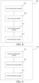
- FIG. 9 shows another schematic structural diagram of a PMI parameter obtaining apparatus for multi-TRP joint transmission according to embodiments of this application.
- the apparatus 900 mainly includes: a second configuration module 901, a second receiving module 902 and a fourth obtaining module 903.
- the second configuration module 901 is configured to configure for a terminal multiple reference signals for determining a PMI parameter for joint transmission, where one of the reference signals is associated with one TRP, and the multiple reference signals include a first reference signal and a second reference signal.
- the second receiving module 902 is configured to receive from the terminal a second target PMI parameter corresponding to the second reference signal and an offset of a first target PMI parameter of the first reference signal relative to the second target PMI parameter.
- the fourth obtaining module 903 is configured to obtain the second target PMI parameter corresponding to the second reference signal and the first target PMI parameter corresponding to the first reference signal according to the second target PMI parameter and the offset of the first target PMI parameter relative to the second target PMI parameter.
- the second configuration module 901 is further configured to configure a high-layer signaling for the terminal, where the high-layer signaling indicates division of the multiple reference signals into at least one reference signal group, and target PMI parameters corresponding to reference signals in the same reference signal group are identical.
- the at least one reference signal group includes a first reference signal group and a second reference signal group.
- the first reference signal group includes at least one said first reference signals
- the second reference signal group includes at least one said second reference signals.
- the operation of obtaining, by the fourth obtaining module 903, the second target PMI parameter corresponding to the second reference signal and the first target PMI parameter corresponding to the first reference signal according to the second target PMI parameter and the offset of the first target PMI parameter relative to the second target PMI parameter includes: determining that a target PMI parameter of each second reference signal in the second reference signal group is the second target PMI parameter, and determining a first target PMI parameter of each first reference signal in each first reference signal group according to the second target PMI parameter and the offset.
- the PMI parameter obtaining apparatus for multi-TRP joint transmission can implement various processes implemented by the network side device in the method embodiments shown in FIG. 2 to FIG. 5 , and achieve the same technical effect. To avoid repetition, details are not described herein again.
- embodiments of this application further provide a communication device 1000, including a processor 1001 and a memory 1002.
- the memory 1002 stores programs or instructions executable on the processor 1001.
- the programs or instructions, when executed by the processor 1001 implement various steps of the embodiments of the PMI parameter feedback methods 200 and 400 for multi-TRP joint transmission, and can achieve the same technical effect.
- the communication device 1000 is a network side device
- the programs or instructions, when executed by the processor 1001 implement various steps of the embodiments of the PMI parameter obtaining methods 300 and 500 for multi-TRP joint transmission, and can achieve the same technical effect. To avoid repetition, details are not described herein again.
- Embodiments of this application further provide a terminal, including a processor and a communication interface.
- the processor is configured to implement various steps of the embodiments of the PMI parameter feedback methods 200 and 400 for multi-TRP joint transmission.
- the communication interface is configured to communicate with an external device.
- the terminal embodiments correspond to the method embodiments at the terminal side.
- Various implementation processes and implementations of the method embodiments are applicable to the terminal embodiments and can achieve the same technical effect.
- FIG. 11 is a schematic diagram of a hardware structure of a terminal implementing embodiments of this application.
- the terminal 1100 includes, but is not limited to, at least some components of a radio frequency unit 1101, a network module 1102, an audio output unit 1103, an input unit 1104, a sensor 1105, a display unit 1106, a user input unit 1107, an interface unit 1108, a memory 1109, a processor 1110, and the like.
- the terminal 1100 may further include a power supply (for example, a battery) for supplying power to the components.
- the power supply may be logically connected to the processor 1110 by a power management system, thereby implementing functions such as charging, discharging, and power consumption management by using the power management system.
- the terminal structure shown in FIG. 11 does not constitute a limitation on the terminal, and the terminal may include more or fewer components than shown, or combine some components, or have different component arrangements. Details are not described herein again.
- the input unit 1104 may include a graphics processing unit (Graphics Processing Unit, GPU) 11041 and a microphone 11042.
- the GPU 11041 performs processing on image data of a static picture or a video that is obtained by an image acquisition apparatus (for example, a camera) in a video acquisition mode or an image acquisition mode.
- the display unit 1106 may include a display panel 11061.
- the display panel 11061 may be configured in a form of a liquid crystal display and an organic light-emitting diode.
- the user input unit 1107 includes at least one of a touch panel 11071 and another input device 11072.
- the touch panel 11071 is also referred to as a touch screen.
- the touch panel 11071 may include two parts: a touch detection apparatus and a touch controller.
- the another input device 11072 may include, but is not limited to, a physical keyboard, a functional key (for example, a volume control key or a switch key), a track ball, a mouse, and a joystick. Details are not described herein again.
- the radio frequency unit 1101 receives downlink data from a network side device and may then transmit the downlink data to the processor 1110 for processing. In addition, the radio frequency unit 1101 may transmit uplink data to the network side device.
- the radio frequency unit 1101 includes, but not limited to, an antenna, an amplifier, a transceiver, a coupler, a low noise amplifier, a duplexer, and the like.
- the memory 1109 may be configured to store software programs or instructions and various data.
- the memory 1109 may mainly include a first storage area for storing programs or instructions and a second storage area for storing data.
- the first storage area may store an operating system, an application program or instruction required by at least one function (for example, a sound playback function and an image display function), and the like.
- the memory 1109 may include a volatile memory or a non-volatile memory, or the memory 1109 may include both a volatile memory and a non-volatile memory.
- the non-volatile memory may be a read-only memory (Read-Only Memory, ROM), a programmable read-only memory (Programmable ROM, PROM), an erasable programmable read-only memory (Erasable PROM, EPROM), an electrically erasable programmable read-only memory (Electrically EPROM, EEPROM) or a flash memory.
- ROM Read-Only Memory
- PROM programmable read-only memory
- Erasable PROM Erasable PROM
- EPROM electrically erasable programmable read-only memory
- EEPROM electrically erasable programmable read-only memory
- the non-volatile memory may be a random access memory (Random Access Memory, RAM), a static random access memory (Static RAM, SRAM) a dynamic random access memory (Dynamic RAM, DRAM), a synchronous dynamic random access memory (Synchronous DRAM, SDRAM), a double data rate synchronous dynamic random access memory (Double Data Rate SDRAM, DDR SDRAM), an enhanced synchronous dynamic random access memory (Enhanced SDRAM, ESDRAM), a synchronous link dynamic random access memory (Synch link DRAM, SLDRAM), and a direct rambus random access memory (Direct Rambus RAM, DRRAM).
- RAM Random Access Memory
- Static RAM static random access memory
- DRAM dynamic random access memory
- DRAM synchronous dynamic random access memory
- SDRAM double data rate synchronous dynamic random access memory
- Enhanced SDRAM, ESDRAM enhanced synchronous dynamic random access memory
- Synch link DRAM, SLDRAM synchronous link dynamic random access memory
- Direct Rambus RAM Direct Rambus RAM, DRRAM
- the processor 1110 may include one or more processing units.
- the processor 1110 integrates an application processor and a modem processor, where the application processor mainly processes operations involving an operating system, a user interface, an application program, and the like, and the modem processor mainly processes wireless communication signals, for example, a baseband processor. It will be appreciated that the modem processor may also not be integrated into the processor 1110.
- the processor 1110 is configured to determine, according to target information, that one parameter value is fed back for a target PMI parameter corresponding to multiple target reference signals among multiple reference signals, where the multiple reference signals are configured by a network side for determining a PMI parameter for joint transmission, and one of the reference signals is associated with one TRP.
- the radio frequency unit 1101 is configured to transmit a PMI parameter for multi-TRP joint transmission, where for the target PMI parameters of multiple target TRPs associated with the multiple target reference signals, the terminal transmits one parameter value for the target PMI parameters.
- the processor 1110 is configured to: obtain target PMI parameters corresponding to multiple reference signals, where the multiple reference signals are reference signals configured for determining a target PMI parameter for joint transmission, one of the reference signals is associated with one TRP, and the multiple reference signals include a first reference signal and a second reference signal; and obtain an offset of a first target PMI parameter corresponding to the first reference signal relative to a second target PMI parameter corresponding to the second reference signal.
- the radio frequency unit 1101 is configured to transmit the second target PMI parameter and an offset of the first target PMI parameter relative to the second target PMI parameter.
- Embodiments of this application further provide a network side device, including a processor and a communication interface.
- the processor is configured to implement various steps of the embodiments of the PMI parameter obtaining methods 300 and 500 for multi-TRP joint transmission.
- the communication interface is configured to communicate with an external device.
- the network side device embodiments correspond to the method embodiments at the network side device.
- Various implementation processes and implementations of the method embodiments are applicable to the network side device embodiments and can achieve the same technical effect.
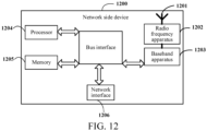
- the network side device 1200 includes: an antenna 1201, a radio frequency apparatus 1202, a baseband apparatus 1203, a processor 1204, and a memory 1205.
- the antenna 1201 is connected to the radio frequency apparatus 1202.
- the radio frequency apparatus 1202 receives information through the antenna 1201 and transmits the received information to the baseband apparatus 1203 for processing.
- the baseband apparatus 1203 processes information to be transmitted and transmits the information to the radio frequency apparatus 1202.
- the received information is processed by the radio frequency apparatus 1202 and is then transmitted through the antenna 1201.
- the method performed by the network side device in the above embodiments may be implemented in the baseband apparatus 1203.
- the baseband apparatus 1203 includes a baseband processor.
- the baseband apparatus 1203 may, for example, include at least one baseband board.
- the baseband board is provided with multiple chips. As shown in FIG. 12 , one of the chips is, for example, the baseband processor, connected to the memory 1205 through a bus interface to call programs in the memory 1205 to perform a network device operation shown in the above method embodiments.
- the network side device may further include a network interface 1206.
- the interface is, for example, a common public radio interface (common public radio interface, CPRI).
- the network side device 1200 in embodiments of this application further includes: instructions or programs stored in the memory 1205 and executable on the processor 1204.
- the processor 1204 calls the instructions or programs in the memory 1205 to execute the method executed by each module in FIG. 8 or FIG. 9 , and achieves the same technical effect. To avoid repetition, details are not described herein again.
- Embodiments of this application further provide a readable storage medium.
- the readable storage medium stores programs or instructions.
- the programs or instructions when executed by a processor, implement various processes of the embodiments of the PMI parameter feedback method for multi-TRP joint transmission or implement various processes of the embodiments of the PMI parameter obtaining method for multi-TRP joint transmission, and can achieve the same technical effect. To avoid repetition, details are not described herein again.
- the processor is a processor in the terminal in the above embodiments.
- the readable storage medium includes a computer-readable storage medium such as a computer read-only memory (ROM), a random access memory (RAM), a magnetic disk, or an optical disc.
- Embodiments of this application additionally provide a chip.
- the chip includes a processor and a communication interface.
- the communication interface is coupled to the processor.
- the processor is configured to execute programs or instructions, to implement various processes of the embodiments of the PMI parameter feedback method for multi-TRP joint transmission or implement various processes of the embodiments of the PMI parameter obtaining method for multi-TRP joint transmission, and can achieve the same technical effect. To avoid repetition, details are not described herein again.
- the chip mentioned in embodiments of this application may also be referred to as a system on chip, a system chip, a system on a chip or a system-on-a-chip, etc.
- Embodiments of this application additionally provide a computer program/program product.
- the computer program/program product is stored in a storage medium.
- the computer program/program product when executed by at least one processor, implements various processes of the embodiments of the PMI parameter feedback method for multi-TRP joint transmission or implements various processes of the embodiments of the PMI parameter obtaining method for multi-TRP joint transmission and can achieve the same technical effect. To avoid repetition, details are not described herein again.
- Embodiments of this application further provide a PMI parameter obtaining system for multi-TRP joint transmission, including: a terminal and a network side device, where the terminal may be configured to execute the steps of the PMI parameter feedback method 200 for multi-TRP joint transmission as described above, and the network side device may be configured to execute the steps of the PMI parameter obtaining method 300 for multi-TRP joint transmission as described above.
- the terminal may be configured to execute the steps of the PMI parameter feedback method 400 for multi-TRP joint transmission as described above
- the network side device may be configured to execute the steps of the PMI parameter obtaining method 500 for multi-TRP joint transmission as described above.
- the method according to the above embodiments may be implemented by software plus a necessary hardware platform. Of course, it may also be implemented by hardware, but in many cases the former is better implementation.
- the technical solutions of this application essentially, or the part contributing to the prior art, may be embodied in a form of a computer software product.
- the computer software product is stored in a storage medium (for example, a ROM/RAM, a magnetic disk, or an optical disc) including several instructions to enable a terminal (which may be a mobile phone, a computer, a server, an air conditioner, a network device, or the like) to perform the method described in each embodiment of this application.
Landscapes
- Engineering & Computer Science (AREA)
- Signal Processing (AREA)
- Computer Networks & Wireless Communication (AREA)
- Physics & Mathematics (AREA)
- Mathematical Physics (AREA)
- Mobile Radio Communication Systems (AREA)
Applications Claiming Priority (2)
| Application Number | Priority Date | Filing Date | Title |
|---|---|---|---|
| CN202210550694.0A CN117134872A (zh) | 2022-05-20 | 2022-05-20 | 多trp联合传输的pmi参数的反馈方法、装置、终端及网络侧设备 |
| PCT/CN2023/095097 WO2023222093A1 (zh) | 2022-05-20 | 2023-05-18 | 多trp联合传输的pmi参数的反馈方法、装置、终端及网络侧设备 |
Publications (2)
| Publication Number | Publication Date |
|---|---|
| EP4529316A1 true EP4529316A1 (de) | 2025-03-26 |
| EP4529316A4 EP4529316A4 (de) | 2025-10-15 |
Family
ID=88834644
Family Applications (1)
| Application Number | Title | Priority Date | Filing Date |
|---|---|---|---|
| EP23807043.7A Pending EP4529316A4 (de) | 2022-05-20 | 2023-05-18 | Pmi-parameter-feedbackverfahren für gemeinsame multi-trp-übertragung, vorrichtung, endgerät und netzwerkseitige vorrichtung |
Country Status (4)
| Country | Link |
|---|---|
| US (1) | US20250088250A1 (de) |
| EP (1) | EP4529316A4 (de) |
| CN (1) | CN117134872A (de) |
| WO (1) | WO2023222093A1 (de) |
Families Citing this family (2)
| Publication number | Priority date | Publication date | Assignee | Title |
|---|---|---|---|---|
| CN120692659A (zh) * | 2024-03-21 | 2025-09-23 | 华为技术有限公司 | 一种通信方法和通信装置 |
| WO2025259145A1 (en) * | 2024-06-11 | 2025-12-18 | Telefonaktiebolaget Lm Ericsson (Publ) | A network node (nn) and methods therein for assisting a ue in transmitting reference signals to the nn in a communication network |
Family Cites Families (5)
| Publication number | Priority date | Publication date | Assignee | Title |
|---|---|---|---|---|
| US11552687B2 (en) * | 2018-06-15 | 2023-01-10 | Nec Corporation | CSI reporting for multiple TRP transmission/panel |
| CN111431687B (zh) * | 2019-01-10 | 2022-02-25 | 华为技术有限公司 | 一种资源指示方法及装置 |
| EP3799506A1 (de) * | 2019-09-30 | 2021-03-31 | Comcast Cable Communications LLC | Downlink-empfang und strahlverwaltung |
| WO2023188156A1 (ja) * | 2022-03-30 | 2023-10-05 | 株式会社Nttドコモ | 端末、無線通信方法及び基地局 |
| WO2023199510A1 (ja) * | 2022-04-15 | 2023-10-19 | 株式会社Nttドコモ | 端末、無線通信方法及び基地局 |
-
2022
- 2022-05-20 CN CN202210550694.0A patent/CN117134872A/zh active Pending
-
2023
- 2023-05-18 EP EP23807043.7A patent/EP4529316A4/de active Pending
- 2023-05-18 WO PCT/CN2023/095097 patent/WO2023222093A1/zh not_active Ceased
-
2024
- 2024-11-19 US US18/952,940 patent/US20250088250A1/en active Pending
Also Published As
| Publication number | Publication date |
|---|---|
| US20250088250A1 (en) | 2025-03-13 |
| WO2023222093A1 (zh) | 2023-11-23 |
| CN117134872A (zh) | 2023-11-28 |
| EP4529316A4 (de) | 2025-10-15 |
Similar Documents
| Publication | Publication Date | Title |
|---|---|---|
| US20250088250A1 (en) | Pmi parameter feedback method and apparatus for multi-trp joint transmission, terminal, and network side device | |
| US20250105889A1 (en) | Pmi parameter feedback method for joint transmission, terminal, and network-side device | |
| US20250015910A1 (en) | Channel feature information transmission method and apparatus, terminal, and network-side device | |
| CN112399402A (zh) | 一种通信方法、装置及设备 | |
| US20200119796A1 (en) | Channel state information transmission method, access network device, and terminal device | |
| EP4648512A1 (de) | Pmi-kombinationskoeffizientenrückkopplungsverfahren und -vorrichtung sowie endgerät und speichermedium | |
| US20250293821A1 (en) | Uplink data transmission method and terminal device | |
| CN116634475B (zh) | 信息上报、确定方法、装置、终端及网络侧设备 | |
| US20250266888A1 (en) | Pmi combination coefficient sending method and apparatus, and terminal | |
| US20250193720A1 (en) | Method for obtaining csi report and communication apparatus | |
| EP4462709A1 (de) | Verfahren und vorrichtung zur rückkopplung von kanalzustandsinformationen (csi), endgerät und netzwerkseitige vorrichtung | |
| CN120956302A (zh) | Csi确定方法、终端及网络侧设备 | |
| US20250055516A1 (en) | Pmi feedback method and device for multi-trp transmission, terminal, and network-side device | |
| CN117318773A (zh) | 信道矩阵处理方法、装置、终端及网络侧设备 | |
| CN118264290A (zh) | 信道特征信息反馈方法、接收方法、终端及网络侧设备 | |
| CN118264281A (zh) | Pmi参数的共享方法、终端及网络侧设备 | |
| US20250047339A1 (en) | Precoding Matrix Feedback Method, Terminal and Network Side Device | |
| CN116996102A (zh) | 多trp传输的pmi的反馈方法、终端及网络侧设备 | |
| US20240356703A1 (en) | Reference signal port indication method, terminal, and network side device | |
| US20260031865A1 (en) | Communication method and communication apparatus | |
| WO2025026152A1 (zh) | 信道状态信息csi传输方法、装置和通信设备 | |
| WO2023151593A1 (zh) | 预编码指示方法、装置、通信设备、系统及存储介质 | |
| CN117792446A (zh) | 参数共享方法、装置、终端、网络侧设备及可读存储介质 | |
| WO2026016972A1 (zh) | 基矢量指示方法、装置、终端及网络侧设备 | |
| CN120239035A (zh) | 功率偏置参数的确定方法、装置、终端及网络侧设备 |
Legal Events
| Date | Code | Title | Description |
|---|---|---|---|
| STAA | Information on the status of an ep patent application or granted ep patent |
Free format text: STATUS: THE INTERNATIONAL PUBLICATION HAS BEEN MADE |
|
| PUAI | Public reference made under article 153(3) epc to a published international application that has entered the european phase |
Free format text: ORIGINAL CODE: 0009012 |
|
| STAA | Information on the status of an ep patent application or granted ep patent |
Free format text: STATUS: REQUEST FOR EXAMINATION WAS MADE |
|
| 17P | Request for examination filed |
Effective date: 20241217 |
|
| AK | Designated contracting states |
Kind code of ref document: A1 Designated state(s): AL AT BE BG CH CY CZ DE DK EE ES FI FR GB GR HR HU IE IS IT LI LT LU LV MC ME MK MT NL NO PL PT RO RS SE SI SK SM TR |
|
| DAV | Request for validation of the european patent (deleted) | ||
| DAX | Request for extension of the european patent (deleted) | ||
| REG | Reference to a national code |
Ref country code: DE Ref legal event code: R079 Free format text: PREVIOUS MAIN CLASS: H04W0072040000 Ipc: H04B0007024000 |
|
| A4 | Supplementary search report drawn up and despatched |
Effective date: 20250915 |
|
| RIC1 | Information provided on ipc code assigned before grant |
Ipc: H04B 7/024 20170101AFI20250909BHEP Ipc: H04B 7/0456 20170101ALI20250909BHEP Ipc: H04W 72/04 20230101ALI20250909BHEP Ipc: H04B 7/06 20060101ALI20250909BHEP Ipc: H04L 5/00 20060101ALI20250909BHEP |