EP4528802A1 - Cooling structure and structure - Google Patents
Cooling structure and structure Download PDFInfo
- Publication number
- EP4528802A1 EP4528802A1 EP23807617.8A EP23807617A EP4528802A1 EP 4528802 A1 EP4528802 A1 EP 4528802A1 EP 23807617 A EP23807617 A EP 23807617A EP 4528802 A1 EP4528802 A1 EP 4528802A1
- Authority
- EP
- European Patent Office
- Prior art keywords
- cooling structure
- inner core
- outer packaging
- packaging material
- concave
- Prior art date
- Legal status (The legal status is an assumption and is not a legal conclusion. Google has not performed a legal analysis and makes no representation as to the accuracy of the status listed.)
- Withdrawn
Links
Images


Classifications
-
- F—MECHANICAL ENGINEERING; LIGHTING; HEATING; WEAPONS; BLASTING
- F28—HEAT EXCHANGE IN GENERAL
- F28F—DETAILS OF HEAT-EXCHANGE AND HEAT-TRANSFER APPARATUS, OF GENERAL APPLICATION
- F28F3/00—Plate-like or laminated elements; Assemblies of plate-like or laminated elements
- F28F3/02—Elements or assemblies thereof with means for increasing heat-transfer area, e.g. with fins, with recesses, with corrugations
- F28F3/025—Elements or assemblies thereof with means for increasing heat-transfer area, e.g. with fins, with recesses, with corrugations the means being corrugated, plate-like elements
-
- H—ELECTRICITY
- H05—ELECTRIC TECHNIQUES NOT OTHERWISE PROVIDED FOR
- H05K—PRINTED CIRCUITS; CASINGS OR CONSTRUCTIONAL DETAILS OF ELECTRIC APPARATUS; MANUFACTURE OF ASSEMBLAGES OF ELECTRICAL COMPONENTS
- H05K7/00—Constructional details common to different types of electric apparatus
- H05K7/20—Modifications to facilitate cooling, ventilating, or heating
- H05K7/20218—Modifications to facilitate cooling, ventilating, or heating using a liquid coolant without phase change in electronic enclosures
- H05K7/20254—Cold plates transferring heat from heat source to coolant
-
- H—ELECTRICITY
- H05—ELECTRIC TECHNIQUES NOT OTHERWISE PROVIDED FOR
- H05K—PRINTED CIRCUITS; CASINGS OR CONSTRUCTIONAL DETAILS OF ELECTRIC APPARATUS; MANUFACTURE OF ASSEMBLAGES OF ELECTRICAL COMPONENTS
- H05K7/00—Constructional details common to different types of electric apparatus
- H05K7/20—Modifications to facilitate cooling, ventilating, or heating
- H05K7/2089—Modifications to facilitate cooling, ventilating, or heating for power electronics, e.g. for inverters for controlling motor
- H05K7/20927—Liquid coolant without phase change
-
- H—ELECTRICITY
- H10—SEMICONDUCTOR DEVICES; ELECTRIC SOLID-STATE DEVICES NOT OTHERWISE PROVIDED FOR
- H10W—GENERIC PACKAGES, INTERCONNECTIONS, CONNECTORS OR OTHER CONSTRUCTIONAL DETAILS OF DEVICES COVERED BY CLASS H10
- H10W40/00—Arrangements for thermal protection or thermal control
- H10W40/40—Arrangements for thermal protection or thermal control involving heat exchange by flowing fluids
- H10W40/47—Arrangements for thermal protection or thermal control involving heat exchange by flowing fluids by flowing liquids, e.g. forced water cooling
-
- F—MECHANICAL ENGINEERING; LIGHTING; HEATING; WEAPONS; BLASTING
- F28—HEAT EXCHANGE IN GENERAL
- F28F—DETAILS OF HEAT-EXCHANGE AND HEAT-TRANSFER APPARATUS, OF GENERAL APPLICATION
- F28F21/00—Constructions of heat-exchange apparatus characterised by the selection of particular materials
- F28F21/08—Constructions of heat-exchange apparatus characterised by the selection of particular materials of metal
-
- F—MECHANICAL ENGINEERING; LIGHTING; HEATING; WEAPONS; BLASTING
- F28—HEAT EXCHANGE IN GENERAL
- F28F—DETAILS OF HEAT-EXCHANGE AND HEAT-TRANSFER APPARATUS, OF GENERAL APPLICATION
- F28F2245/00—Coatings; Surface treatments
-
- H—ELECTRICITY
- H10—SEMICONDUCTOR DEVICES; ELECTRIC SOLID-STATE DEVICES NOT OTHERWISE PROVIDED FOR
- H10W—GENERIC PACKAGES, INTERCONNECTIONS, CONNECTORS OR OTHER CONSTRUCTIONAL DETAILS OF DEVICES COVERED BY CLASS H10
- H10W40/00—Arrangements for thermal protection or thermal control
- H10W40/20—Arrangements for cooling
- H10W40/22—Arrangements for cooling characterised by their shape, e.g. having conical or cylindrical projections
- H10W40/226—Arrangements for cooling characterised by their shape, e.g. having conical or cylindrical projections characterised by projecting parts, e.g. fins to increase surface area
Definitions
- the present disclosure relates to a cooling structure, and a structure.
- the driving means is composed of a power module having a plural power semiconductor such as an IGBT (Insulated Gate Bipolar Transistor), an electronic component such as a capacitor, and a bus bar that electrically connect these electronic components.
- IGBT Insulated Gate Bipolar Transistor
- the driving means When driving a motor, a large current may flow through the bus bar that connects the power semiconductors, capacitors and the like.
- the driving means When driving a motor, a large current may flow through the bus bar that connects the power semiconductors, capacitors and the like.
- the driving means generates heat due to switching loss, resistance loss and the like, and therefore it is desirable to efficiently cool the driving means. It is also desirable to efficiently cool the heat generated by the battery module installed in the vehicle.
- a cooling structure may be a structure made of a metal with high thermal conductivity, such as an aluminum cooling fin core structure.
- a metal with high thermal conductivity such as an aluminum cooling fin core structure.
- it is made of metal, it is heavy, and since it needs to be attached to an object to be cooled by welding or the like, it needs to be a certain thickness, which makes it difficult to make it thin.
- a cooling structure has been proposed in which an outer packaging material and an inner core material are made of a laminate material in which a metal heat transfer layer is laminated with resin layer, and a refrigerant is circulated through a flow path separated by the inner core material (see, for example, Patent Document 1). It is described that a heat exchanger of Patent Document 1 can be sufficiently thinned because it is produced by heat-fusing laminate materials having a heat fusion layer. Furthermore, in the heat exchanger described in Patent Document 1, the shape and size of the laminated materials that serve as the exterior material and the inner core material can be easily changed, which is said to increase design freedom and improve versatility.
- Patent Document 1 Japanese Patent Application Laid-Open ( JP-A) No. 2020-3132
- the heat exchanger described in Patent Document 1 has the above advantages, a technique for further improving the heat exchange efficiency is desired.
- the present disclosure relates to providing a cooling structure and a structure that have excellent heat exchange efficiency.
- Means for solving the above problems include the following embodiments.
- the term "layer” comprehends herein not only a case in which the layer is formed over the whole observed region where the layer is present, but also a case in which the layer is formed only on part of the region.
- laminate refers to stacking layers, and two or more layers may be joined, or two or more layers may be detachable.
- a cooling structure in the present disclosure is a cooling structure including an outer packaging material having an inlet and an outlet for a refrigerant, and an inner core material disposed inside the outer packaging material, in which the inner core material has a concave and convex shape that divides the flow path of the refrigerant into multiple sections, and at least one of an inclination from a concave portion to a convex portion or an inclination from a convex portion to a concave portion in the concave and convex shape is 10° or more and less than 90° with respect to a surface direction of the cooling structure.
- FIG. 1 shows a schematic partial cross-sectional view in the width direction (Orthogonal to the direction of refrigerant flow) of a cooling structure according to one embodiment in the present disclosure.
- the inner core material 10 has a concave and convex shape that divides a flow path of the refrigerant into multiple sections. And at least one of an inclinations ⁇ 1 from a concave portion 12 to a convex portion 14 or an inclination ⁇ 2 from a convex portion 14 to a concave portion 12 in the concave and convex shape is 10° or more and less than 90° with respect to a surface direction of the cooling structure.
- the concave portion 12 and the convex portion 14 of the inner core material 10 contact outer packaging materials 20A and 20B, respectively, and divide the flow path of the refrigerant into multiple sections, forming flow paths 30, 31 and the like.
- the outer packaging materials 20A and 20B are also collectively referred to as the outer packaging materials 20.
- FIG. 2 is a schematic partial cross-sectional view in the width direction of a cooling structure in a case in which inclinations ⁇ 1 and ⁇ 2 are 90°.
- FIGs 1 and 2 are shown so that the intervals between the convex portions are the same.
- the cooling structure in FIG. 1 in which at least one of the inclinations ⁇ 1 or ⁇ 2 is 10° or more and less than 90°, has a smaller contact area between the outer packaging material 20A and the concave portion 12, and a smaller contact area between the outer packaging material 20B and the convex portion 14, compared to the cooling structure in FIG. 2 , in which the inclinations ⁇ 1 and ⁇ 2 are 90°. Therefore, the cooling structure in FIG. 1 has a superior heat exchange efficiency to the cooling structure in FIG. 2 .
- the inner core material 10 is partially inclined in the thickness direction, so that the pressing force in the thickness direction can be released in the surface direction, and it is also possible to suppress damage to the inner core material 10 due to pressing.
- the inclination ⁇ 1 refers to an acute angle of an inclination from the concave portion 12 to the convex portion 14 with respect to the surface direction of the cooling structure.
- the inclination ⁇ 2 refers to an acute angle of the inclination from the convex portion 14 to the concave portion 12 with respect to the surface direction of the cooling structure.
- the inclination from the concave portion 12 to the convex portion 14 and the inclination from the convex portion 14 to the concave portion 12 do not have to be uniform.
- the inclination of the inner core material 10 from the concave portion 12 to the convex portion 14 is approximated as a straight line A, and an acute angle between this straight line A and the surface direction of the cooling structure is the inclination ⁇ 1.
- the inclination of the inner core material 10 from the concave portion 12 to the convex portion 14 is approximated as a straight line B, and an acute angle between this straight line B and the surface direction of the cooling structure is the inclination ⁇ 2.
- a bottom of the concave portion 12 and a top of the convex portion 14 are shown as flat surfaces, but they may be curved surfaces instead of flat surfaces. It is preferable that at least one of the bottom of the concave portion 12 or the top of the convex portion 14 has a flat surface. In a case in which at least one of the bottom of the concave portion 12 or the top of the convex portion 14 has a flat surface, it becomes easier to fuse the inner core material 10 to the outer packaging material 20. In a case in which at least one of the concave portion 12 or the convex portion 14 of the inner core material 10 is fused to the outer packaging material 20, a positional deviation of the inner core material 10 is suppressed.
- the inclinations ⁇ 1 and ⁇ 2 may be the same or different. From the viewpoints of simplifying manufacturing and strength, it is preferable that the inclination ⁇ 1 and the inclination ⁇ 2 are the same.
- Each of the inclination ⁇ 1 and the inclination ⁇ 2 is independently 10° or more, preferably 20° or more, more preferably 30° or more, and even more preferably 45° or more.
- Each of the inclination ⁇ 1 and the inclination ⁇ 2 is independently less than 90°, preferably 80° or less, more preferably 70° or less, and even more preferably 60° or less.
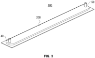
- FIG. 3 is a schematic perspective view showing an appearance of a cooling structure 100 according to one embodiment in the present disclosure.
- the cooling structure 100 shown in FIG. 3 has an inlet 40 and an outlet 50 for a refrigerant, and is entirely covered with an outer packaging material 20.
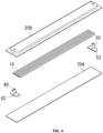
- FIG. 4 is an exploded view of the cooling structure 100 of FIG. 3 , separated into its individual components.
- the outer packaging material 20 is composed of an upper outer packaging material 20A and a lower outer packaging material 20B.
- the upper and lower are written according to a top and bottom in the drawings, but the top and bottom may be reversed.
- a material of the outer packaging material 20 is not particularly limited, but is preferably a metal from the viewpoint of thermal conductivity.
- Examples of the outer packaging material 20 include aluminum foil, stainless steel foil, nickel foil, plated copper foil, and clad metal of nickel foil and copper foil. From the viewpoint of thermal conductivity, cost or the like, aluminum foil is preferable.
- the outer packaging material 20 may have a metal layer and a resin layer provided on at least one surface of the metal layer.
- a resin layer By providing a resin layer on an inside surface of the outer packaging material 20, an occurrence of corrosion due to the refrigerant is easily suppressed.
- insulation may be achieved.
- the metal layer and the resin layer may be laminated to form a laminate material. Another layer may or may not be provided between the metal layer and the inner resin layer.
- the lower outer packaging material 20A and the upper outer packaging material 20B may be made of the same material or different materials.
- the metal layer in the laminate material is preferably made of the metals mentioned above.
- the resin layer in the laminate material is preferably composed of a resin having thermal fusion property, and examples of the resin include a polyolefin resin such as polyethylene, polypropylene or modified resins thereof, a fluorine-based resin, a polyester resin such as PET resin, and vinyl chloride resin.
- a thickness of the metal layer is preferably 4 ⁇ m or more, and more preferably 8 ⁇ m or more.
- the thickness of the metal layer is preferably 300 ⁇ m or less, and more preferably 150 ⁇ m or less.
- a thickness of the resin layer is preferably 4 ⁇ m or more, and more preferably 8 ⁇ m or more.
- the thickness of the resin layer is preferably 300 ⁇ m or less, and more preferably 150 ⁇ m or less.
- a coating layer may be provided on the outermost layer of the laminate material.
- the coating layer By providing the coating layer on the outer packaging material 20, a corrosion of the metal layer is prevented, and damage due to external and internal pressure tends to be prevented.
- an insulating resin is used for the coating layer, it tends to be possible to impart effects such as preventing short circuits and electric leakage to the object to be cooled.
- a conductive resin is used for the coating layer, it tends to be possible to impart an antistatic effect to the object to be cooled.
- the same resin as that for the resin layer described above may be used.
- the coating layer may be made of the same material as the resin layer, or a different material. From the viewpoint of fusing between the outer packaging material 20 and the inner core material 10, it is preferable to use a coating layer having a higher melting point than the resin layer, and it is particularly preferable to use a resin having a melting point 10°C or more higher.
- a thickness of the coating layer is not particularly limited, and it is preferable to set it to the same thickness as the resin layer or thinner than the resin layer.
- a thickness of the outer packaging material 20 is not particularly limited. From the viewpoint of strength and thermal conductivity, it is preferable that the thickness of the outer packaging material 20 is 8 ⁇ m or more, more preferably 10 ⁇ m or more, and even more preferably 12 ⁇ m or more. From the viewpoint of thinning and deformability, it is preferable that the thickness of the outer packaging material 20 is 300 ⁇ m or less, more preferably 250 ⁇ m or less, and even more preferably 200 ⁇ m or less. From these viewpoints, the thickness of the outer packaging material 20 is preferably from 8 ⁇ m to 300 ⁇ m, more preferably from 10 ⁇ m to 250 ⁇ m, and even more preferably from 12 ⁇ m to 200 ⁇ m.
- the laminate material may be produced by attaching a resin film to a metal foil or metal plate.
- the resin film may be a stretched film or a non-stretched film.
- An adhesive may be used for attachment.
- the upper outer packaging material 20B is provided with holes for passing through a joint pipe as the inlet 40 and a joint pipe as the outlet 50.
- the joint pipe of the inlet 40 is provided as a part of a header part 42
- the joint pipe of the outlet 50 is provided as a part of a footer part 52.
- the joint pipe of the inlet 40 may be molded integrally with the header part 42
- the joint pipe of the outlet 50 may be molded integrally with the footer part 52.
- the joint pipes extends outward in a thickness direction of the cooling structure 100, but the orientation of the joint pipes are not limited to this.
- the joint pipes may extend outward in a surface direction of the cooling structure 100.
- the joint pipe of the inlet 40 and the joint pipe of the outlet 50 may be oriented in different directions.
- An inner core material 10 is disposed inside the outer packaging material 20 so that the inner core material 10 divides the flow path of the refrigerant flowing from the header part 42 to the footer part 52 into multiple parts.
- a periphery of the upper outer packaging material 20B and the lower outer packaging material 20A are closed to seal.
- the outer packaging material 20A and the outer packaging material 20B have a resin layer
- a periphery of the upper lower outer packaging material 20B and the lower outer packaging material 20A can be closed and sealed by fusing the resin layer.
- a material of the inner core material 10 is not particularly limited, and may be a resin, a metal or the like, or may be a laminate material in which a metal layer and a resin layer are laminated.
- the inner core material 10 may have a metal layer and resin layers provided on both sides of the metal layer.
- the surface of the inner core material 10 is made of resin, it may be fused to the outer packaging material 20.
- the surface of the inner core material 10 is made of resin, an occurrence of corrosion due to the refrigerant is more easily suppressed.
- the metal layer of the inner core material 10 may suitably be the same as the metal layer of the outer packaging material 20.
- the metal layer of the laminate material as the inner core material 10 may be made of the same material as the metal layer of the laminate material as the outer packaging material 20, or may be made of a different material.
- the resin layer of the laminate material as the inner core material 10 may suitably be the same material as the resin layer of the laminate material as the outer packaging material 20. From the viewpoint of thermally fusing the inner core material 10 to the outer packaging material 20, it is preferable that the resin layer of the laminate material as the inner core material 10 and the resin layer of the laminate material as the outer packaging material 20 are made of the same material.
- the laminate material as the inner core material 10 may be produced by attaching a resin film to a metal foil or metal plate.
- the resin film may be a stretched film or a non-stretched film.
- An adhesive may be used for attachment.
- the inner core material 10 may be made of an elastically deformable material.
- the inner core material 10 may be made of at least one material selected from the group consisting of metals such as iron and stainless steel, and resin.
- the inner core material may be a metal layer such as iron or stainless steel coated with resin.
- the resin layer in this case is the same as the resin layer described above.
- the inner core material 10 is made of an elastically deformable material
- the inner core material 10 is made of an elastically deformable material
- the outer packaging material 20 even if the bottom of the concave portion 12 and the top of the convex portion 14 of the inner core material 10 are fused to the outer packaging material 20 and restrained, when an external force is applied from the lower outer packaging material 20A side or the upper outer packaging material 20B side, a region between the concave portion 12 and the convex portion 14 will bend and deform. Then, a thickness of the cooling structure 100 to which an external force is applied becomes thinner than a thickness of the cooling structure 100 before the external force is applied, while maintaining a state of being arranged along a surface of the object to be cooled.
- the inner core material 10 is elastically deformable, when the external force is removed or reduced, a bending deformation returns to the original direction, and the thickness of the cooling structure 100 increases. In this way, in a case in which the inner core material 10 is made of an elastically deformable material, the cooling structure 100 becomes deformable due to the external force, and also becomes deformable in response to a shape and change in shape of the object to be cooled.
- the concave and convex shape of the inner core material 10 may be formed into a corrugated shape by pressing, pleating or the like. It may not only be a corrugated shape, but also an embossed shape with concave and convex portions distributed like a houndstooth pattern.
- the pressing may be a discontinuous press or a continuous press.
- the discontinuous press include a forming method using an upper plate and a lower plate
- Examples of the continuous press include a roll forming method.
- Examples of the roll forming method include a corrugated processing method.
- each of the upper plate and the lower plate is formed so that the concave and convex portions are arranged alternately.
- Each concave portion of the upper plate corresponds to each convex portion of the lower plate, and each convex portion of the upper plate corresponds to each concave portion of the lower plate, and the upper plate and the lower plate are configured so that the concave and convex portions of each plate interlock with each other.
- the inner core before processing may be formed into a corrugated shape by sandwiching and pressing the inner core between the upper plate and the lower plate.
- the corrugated processing method may be performed using a pair of corrugated rolls.
- Each corrugated roll is formed so that concave and convex portions are arranged alternately along a rotational direction on its outer circumferential surface.
- Each concave portion of one corrugated roll corresponds to each convex portion of the other corrugated roll, and each convex portion of one corrugated roll corresponds to each concave portion of the other corrugated roll, and the pair of corrugated rolls are configured so that their concave and convex portions interlock with each other.
- the inner core material may be passed between the pair of corrugated rolls and formed into a corrugated sheet shape.
- a pair of embossing rolls may be used.
- an embossing rolls are used, in which concave and convex portions of the embossing rolls are arranged alternately on the outer circumferential surface along a rotational direction and an axial direction.
- the pair of embossing rolls are arranged so that the concave portions of one embossing roll correspond to the convex portions of the other embossing roll, and the convex portions of one embossing roll correspond to the concave portions of the other embossing roll, so that the pair of embossing rolls are arranged so that the concave and convex portions interlock with each other.
- the inner core material before processing is sandwiched between the pair of embossing rolls and rotated, and the inner core laminate material is passed between the pair of embossing rolls to process the concave and convex portions.
- the inner core material processed with the concave and convex portions is cut to a predetermined length by a shear knife (shear cutting blade) or the like provided downstream of the processing device to form the inner core material 10.
- a shear knife shear cutting blade
- the process may be performed continuously by roll-to-roll, and the production efficiency may be improved.
- the cross-sectional shape of the refrigerant flow path is not uniform, it is preferable to process the inner core material by discontinuous pressing.
- the concave and convex shapes may be formed by vacuum molding.
- At least one of an interval between the convex portions 14 or an interval between the concave portions 12 may be from 2 mm to 10 mm.
- the interval between the convex portions 14 and the interval between the concave portions 12 may be adjusted as appropriate depending on a number of refrigerant flow paths separated by the concave and convex shape, an overall size of the cooling structure, or the like.
- the interval between the convex portions 14 refers to a distance from one convex portion 14 to the next adjacent convex portion 14.
- the interval between the convex portions 14 refers to a distance from an end point of the flat surface of one convex portion 14 to a start point of the flat surface of the next adjacent convex portion 14.
- the interval between the convex portions 14 refers to a distance from the highest point of one convex portion 14 to the highest point of the next adjacent convex portion 14.
- a cross-sectional shape of the refrigerant flow path partitioned by the concave and convex shapes of the inner core material 10 may be a semicircle, a semi-ellipse, a polygonal shape such as a triangle, a rectangle or a pentagon, an irregular shape, or a combination of these.
- the multiple concave and convex shapes may be arranged regularly or irregularly.
- Examples of an irregular arrangement include one in which the period of the concave portion and convex portion is not uniform. In the case of a regular arrangement, the period of the concave portions and the period of the convex portions may be the same or different.
- a refrigerant flows through the flow path that is partitioned into multiple parts by the concave and convex shape of the inner core material 10.
- a kind of the refrigerant is not particularly limited.
- Examples of the refrigerant include liquids such as water and organic solvents, and gases such as air.
- the water used as the refrigerant may contain components such as antifreeze.
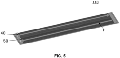
- FIG. 5 is a schematic perspective view illustrating a modified example of the cooling structure, showing an interior in a case in which the upper outer packaging material 20B is removed.
- the inlet 40 and outlet 50 for the refrigerant are provided at each end (front end, rear end) in the length direction.
- both the inlet 40 and the outlet 50 are provided at one end.
- a joint pipe for the inlet 40 and a joint pipe for the outlet 50 are provided in the header section 42.
- the refrigerant that flows from the inlet 40 of the header part 42 makes a U-turn at the footer part 52, reverses direction, and returns to the outlet 50 of the header section 42.
- the refrigerant makes one round trip in the length direction, but it may make one and a half round trips.
- the header part 42 may be provided with an inlet 40, and the footer part 52 may be provided with an outlet 50. A number of times the refrigerant travels back and forth may be further increased.
- the cooling structure in the present disclosure may be widely used to cool heat-generating bodies, and is effective for cooling, for example, electronic devices such as smartphones and personal computers, battery modules mounted on electric vehicles, hybrid vehicles or the like, and power semiconductor modules.
- the structure in the present disclosure includes the cooling structure in the present disclosure described above, and an object to be cooled provided on the cooling structure.
- Examples of the object to be cooled include heat-generating electronic devices such as smartphones and personal computers, battery modules mounted on electric vehicles and hybrid vehicles or the like, and power semiconductor modules.
- the object to be cooled may be provided on either the outer packaging material 20B side or the outer packaging material 20A side of the cooling structure 100, or may be provided on both sides.
Landscapes
- Engineering & Computer Science (AREA)
- Microelectronics & Electronic Packaging (AREA)
- Physics & Mathematics (AREA)
- Thermal Sciences (AREA)
- Mechanical Engineering (AREA)
- General Engineering & Computer Science (AREA)
- Cooling Or The Like Of Electrical Apparatus (AREA)
- Cooling Or The Like Of Semiconductors Or Solid State Devices (AREA)
Abstract
Description
- The present disclosure relates to a cooling structure, and a structure.
- In the field of electronic devices such as smartphones and personal computers, and battery modules mounted on electric vehicles, hybrid vehicles and the like, techniques for incorporating water-cooling devices, heat pipes and the like as heat generation countermeasures are known. Also, in power semiconductor modules made of silicon carbide or the like, measures using cooling plates, heat sinks or the like as heat generation countermeasures have been proposed.
- For example, vehicles equipped with motors such as hybrid cars and electric cars, are equipped with a driving means for driving the motor. The driving means is composed of a power module having a plural power semiconductor such as an IGBT (Insulated Gate Bipolar Transistor), an electronic component such as a capacitor, and a bus bar that electrically connect these electronic components. When driving a motor, a large current may flow through the bus bar that connects the power semiconductors, capacitors and the like. In this case, the driving means generates heat due to switching loss, resistance loss and the like, and therefore it is desirable to efficiently cool the driving means. It is also desirable to efficiently cool the heat generated by the battery module installed in the vehicle.
- A cooling structure may be a structure made of a metal with high thermal conductivity, such as an aluminum cooling fin core structure. However, since it is made of metal, it is heavy, and since it needs to be attached to an object to be cooled by welding or the like, it needs to be a certain thickness, which makes it difficult to make it thin.
- Therefore, from the viewpoint of reducing weight and the like, a cooling structure has been proposed in which an outer packaging material and an inner core material are made of a laminate material in which a metal heat transfer layer is laminated with resin layer, and a refrigerant is circulated through a flow path separated by the inner core material (see, for example, Patent Document 1). It is described that a heat exchanger of Patent Document 1 can be sufficiently thinned because it is produced by heat-fusing laminate materials having a heat fusion layer. Furthermore, in the heat exchanger described in Patent Document 1, the shape and size of the laminated materials that serve as the exterior material and the inner core material can be easily changed, which is said to increase design freedom and improve versatility.
- Patent Document 1: Japanese Patent Application Laid-Open (
JP-A) No. 2020-3132 - Although the heat exchanger described in Patent Document 1 has the above advantages, a technique for further improving the heat exchange efficiency is desired. In view of such circumstances, the present disclosure relates to providing a cooling structure and a structure that have excellent heat exchange efficiency.
- Means for solving the above problems include the following embodiments.
- <1> A cooling structure comprising an outer packaging material having an inlet and an outlet for a refrigerant, and an inner core material disposed inside the outer packaging material,
- in which the inner core material has a concave and convex shape that divides a flow path of the refrigerant into multiple sections, and
- in which at least one of an inclination from a concave portion to a convex portion or an inclination from a convex portion to a concave portion in the concave and convex shape is 10° or more and less than 90° with respect to a surface direction of the cooling structure.
- <2> The cooling structure according to <1>, in which at least one of a bottom of the concave portion or a top of the convex portion has a flat surface.
- <3> The cooling structure according to <2>, in which the flat surface is fused to the outer packaging material.
- <4> The cooling structure according to any one of <1> to <3>, in which the outer packaging material includes a metal layer and a resin layer provided on at least one surface of the metal layer.
- <5> The cooling structure according to any one of <1> to <4>, in which the inner core material includes a metal layer and a resin layer provided on both surfaces of the metal layer.
- <6> The cooling structure according to any one of <1> to <5>, in which the inner core material is made of an elastically deformable material.
- <7> The cooling structure according to any one of <1> to <6>, in which at least one of a spacing between concave portions or a spacing between convex portions is from 2 mm to 10 mm.
- <8> A structure including the cooling structure according to any one of <1> to <7> and an object to be cooled provided on the cooling structure.
- According to the present disclosure, it is possible to provide a cooling structure and a structure that have excellent heat exchange efficiency.
-
-
FIG. 1 is a schematic partial cross-sectional view in the width direction of a cooling structure according to one embodiment in the present disclosure. -
FIG. 2 is a schematic partial cross-sectional view in the width direction of a cooling structure in a case in which inclinations θ1 and θ2 are 90°. -
FIG. 3 is a schematic perspective view showing an appearance of a cooling structure according to one embodiment in the present disclosure. -
FIG. 4 is an exploded view of the cooling structure ofFIG. 3 separated into its individual components. -
FIG. 5 is a schematic perspective view illustrating a modified example of the cooling structure, showing an interior in a case in which an upper outer packaging material is removed. - Hereinafter, embodiments in the present disclosure will be described in detail. It is to be noted, however, that the present disclosure is not limited to the following embodiments. In the embodiments described below, components thereof (including element steps and the like) are not essential, unless otherwise specified. The same applies to numerical values and ranges thereof, and the present disclosure is not limited thereto.
- In a case in which the embodiments in the present disclosure are described with reference to the drawings, a configuration of embodiments is not limited to the configuration shown in the drawings. Furthermore, the sizes of the members in each figure are conceptual, and the relative size relationships between the members are not limited thereto. Further, in each drawing, members having substantially the same function are given the same reference numerals in all drawings, and duplicated explanations will be omitted.
- In the present disclosure, the term "layer" comprehends herein not only a case in which the layer is formed over the whole observed region where the layer is present, but also a case in which the layer is formed only on part of the region.
- In the present disclosure, the term "laminate" refers to stacking layers, and two or more layers may be joined, or two or more layers may be detachable.
- A cooling structure in the present disclosure is a cooling structure including an outer packaging material having an inlet and an outlet for a refrigerant, and an inner core material disposed inside the outer packaging material, in which the inner core material has a concave and convex shape that divides the flow path of the refrigerant into multiple sections, and at least one of an inclination from a concave portion to a convex portion or an inclination from a convex portion to a concave portion in the concave and convex shape is 10° or more and less than 90° with respect to a surface direction of the cooling structure.
-
FIG. 1 shows a schematic partial cross-sectional view in the width direction (Orthogonal to the direction of refrigerant flow) of a cooling structure according to one embodiment in the present disclosure. Theinner core material 10 has a concave and convex shape that divides a flow path of the refrigerant into multiple sections. And at least one of an inclinations θ1 from aconcave portion 12 to aconvex portion 14 or an inclination θ2 from aconvex portion 14 to aconcave portion 12 in the concave and convex shape is 10° or more and less than 90° with respect to a surface direction of the cooling structure. Theconcave portion 12 and theconvex portion 14 of theinner core material 10 contactouter packaging materials flow paths outer packaging materials - In a case in which an object to be cooled that is placed on the
outer packaging material 20A side is cooled, if we focus onflow path 30, it is cooled by the refrigerant inflow path 30 through theouter packaging material 20A. Focusing onflow path 31, it is cooled by the refrigerant inflow path 31 through theouter packaging material 20A and theinner core material 10. In other words, in theflow path 31, the refrigerant moves away from the object to be cooled by a distance equal to a total thickness of theouter packaging material 20A and theinner core material 10. - Similarly, in a case in which c an object to be cooled that is placed on the
outer packaging material 20B side is cooled,, if we focus onflow path 31, it is cooled by the refrigerant inflow path 31 through theouter packaging material 20B. Focusing on theflow path 30, it is cooled by the refrigerant inflow path 30 through theouter packaging material 20B and theinner core material 10. In other words, in theflow path 30, the refrigerant moves away from the object to be cooled by a distance equal to a total thickness of theouter packaging material 20B and theinner core material 10. -
FIG. 2 is a schematic partial cross-sectional view in the width direction of a cooling structure in a case in which inclinations θ1 and θ2 are 90°.FIGs 1 and2 are shown so that the intervals between the convex portions are the same. The cooling structure inFIG. 1 , in which at least one of the inclinations θ1 or θ2 is 10° or more and less than 90°, has a smaller contact area between theouter packaging material 20A and theconcave portion 12, and a smaller contact area between theouter packaging material 20B and theconvex portion 14, compared to the cooling structure inFIG. 2 , in which the inclinations θ1 and θ2 are 90°. Therefore, the cooling structure inFIG. 1 has a superior heat exchange efficiency to the cooling structure inFIG. 2 . - In addition, in a case in which the cooling structure is pressed against the object to be cooled, which is a heat generating body, in the cooling structure of
FIG. 1 , theinner core material 10 is partially inclined in the thickness direction, so that the pressing force in the thickness direction can be released in the surface direction, and it is also possible to suppress damage to theinner core material 10 due to pressing. - Here, the inclination θ1 refers to an acute angle of an inclination from the
concave portion 12 to theconvex portion 14 with respect to the surface direction of the cooling structure. The inclination θ2 refers to an acute angle of the inclination from theconvex portion 14 to theconcave portion 12 with respect to the surface direction of the cooling structure. The inclination from theconcave portion 12 to theconvex portion 14 and the inclination from theconvex portion 14 to theconcave portion 12 do not have to be uniform. - In a case in which an inclination from the
concave portion 12 to theconvex portion 14 is not uniform, the inclination of theinner core material 10 from theconcave portion 12 to theconvex portion 14 is approximated as a straight line A, and an acute angle between this straight line A and the surface direction of the cooling structure is the inclination θ1. In a case in which an inclination from theconvex portion 14 to theconcave portion 12 is not uniform, the inclination of theinner core material 10 from theconcave portion 12 to theconvex portion 14 is approximated as a straight line B, and an acute angle between this straight line B and the surface direction of the cooling structure is the inclination θ2. - In
FIG. 1 , a bottom of theconcave portion 12 and a top of theconvex portion 14 are shown as flat surfaces, but they may be curved surfaces instead of flat surfaces. It is preferable that at least one of the bottom of theconcave portion 12 or the top of theconvex portion 14 has a flat surface. In a case in which at least one of the bottom of theconcave portion 12 or the top of theconvex portion 14 has a flat surface, it becomes easier to fuse theinner core material 10 to the outer packaging material 20. In a case in which at least one of theconcave portion 12 or theconvex portion 14 of theinner core material 10 is fused to the outer packaging material 20, a positional deviation of theinner core material 10 is suppressed. - In the cooling structure of
FIG. 2 having the inclinations θ1 and θ2 of 90°, if intervals between the convex portions and the intervals between the concave portions are reduced for reducing the contact area between the outer packaging material 20 and theinner core material 10, a total number of convex portions and processing cost will increase. Note that even if the intervals between the convex portions and the intervals between the concave portions is reduced, a total contact area between the outer packaging material 20 and theinner core material 10 will not decrease. - From the same viewpoint, in the cooling structure of
FIG. 2 having the inclinations θ1 and θ2 of 90°, if the bottom of theconcave portion 12 and the top of theconvex portion 14 are curved, a contact between theinner core material 10 and the outer packaging material 20 will be point contact or line contact, making it difficult to fuse theinner core material 10 to the outer packaging material 20. In a case in which the outer packaging material 20 and theinner core material 10 are firmly fused, it will be easier to withstand the internal pressure caused by the flow of the refrigerant. - The inclinations θ1 and θ2 may be the same or different. From the viewpoints of simplifying manufacturing and strength, it is preferable that the inclination θ1 and the inclination θ2 are the same.
- Each of the inclination θ1 and the inclination θ2 is independently 10° or more, preferably 20° or more, more preferably 30° or more, and even more preferably 45° or more. Each of the inclination θ1 and the inclination θ2 is independently less than 90°, preferably 80° or less, more preferably 70° or less, and even more preferably 60° or less.
-
FIG. 3 is a schematic perspective view showing an appearance of acooling structure 100 according to one embodiment in the present disclosure. Thecooling structure 100 shown inFIG. 3 has aninlet 40 and anoutlet 50 for a refrigerant, and is entirely covered with an outer packaging material 20. -
FIG. 4 is an exploded view of thecooling structure 100 ofFIG. 3 , separated into its individual components. - The outer packaging material 20 is composed of an upper
outer packaging material 20A and a lowerouter packaging material 20B. In the present disclosure, the upper and lower are written according to a top and bottom in the drawings, but the top and bottom may be reversed. - A material of the outer packaging material 20 is not particularly limited, but is preferably a metal from the viewpoint of thermal conductivity. Examples of the outer packaging material 20 include aluminum foil, stainless steel foil, nickel foil, plated copper foil, and clad metal of nickel foil and copper foil. From the viewpoint of thermal conductivity, cost or the like, aluminum foil is preferable.
- In one embodiment, the outer packaging material 20 may have a metal layer and a resin layer provided on at least one surface of the metal layer. By providing a resin layer on an inside surface of the outer packaging material 20, an occurrence of corrosion due to the refrigerant is easily suppressed. Whereas, by providing a resin layer on the outside surface of the outer packaging material 20, insulation may be achieved. The metal layer and the resin layer may be laminated to form a laminate material. Another layer may or may not be provided between the metal layer and the inner resin layer. The lower
outer packaging material 20A and the upperouter packaging material 20B may be made of the same material or different materials. - The metal layer in the laminate material is preferably made of the metals mentioned above.
- The resin layer in the laminate material is preferably composed of a resin having thermal fusion property, and examples of the resin include a polyolefin resin such as polyethylene, polypropylene or modified resins thereof, a fluorine-based resin, a polyester resin such as PET resin, and vinyl chloride resin.
- A thickness of the metal layer is preferably 4 µm or more, and more preferably 8 µm or more. The thickness of the metal layer is preferably 300 µm or less, and more preferably 150 µm or less.
- A thickness of the resin layer is preferably 4 µm or more, and more preferably 8 µm or more. The thickness of the resin layer is preferably 300 µm or less, and more preferably 150 µm or less.
- A coating layer may be provided on the outermost layer of the laminate material. By providing the coating layer on the outer packaging material 20, a corrosion of the metal layer is prevented, and damage due to external and internal pressure tends to be prevented. In addition, in a case in which an insulating resin is used for the coating layer, it tends to be possible to impart effects such as preventing short circuits and electric leakage to the object to be cooled. Whereas, in a case in which a conductive resin is used for the coating layer, it tends to be possible to impart an antistatic effect to the object to be cooled.
- As the resin for the coating layer, the same resin as that for the resin layer described above may be used. The coating layer may be made of the same material as the resin layer, or a different material. From the viewpoint of fusing between the outer packaging material 20 and the
inner core material 10, it is preferable to use a coating layer having a higher melting point than the resin layer, and it is particularly preferable to use a resin having amelting point 10°C or more higher. - A thickness of the coating layer is not particularly limited, and it is preferable to set it to the same thickness as the resin layer or thinner than the resin layer.
- A thickness of the outer packaging material 20 is not particularly limited. From the viewpoint of strength and thermal conductivity, it is preferable that the thickness of the outer packaging material 20 is 8 µm or more, more preferably 10 µm or more, and even more preferably 12 µm or more. From the viewpoint of thinning and deformability, it is preferable that the thickness of the outer packaging material 20 is 300 µm or less, more preferably 250 µm or less, and even more preferably 200 µm or less. From these viewpoints, the thickness of the outer packaging material 20 is preferably from 8 µm to 300 µm, more preferably from 10 µm to 250 µm, and even more preferably from 12 µm to 200 µm.
- The laminate material may be produced by attaching a resin film to a metal foil or metal plate. The resin film may be a stretched film or a non-stretched film. An adhesive may be used for attachment.
- In
FIG. 4 , the upperouter packaging material 20B is provided with holes for passing through a joint pipe as theinlet 40 and a joint pipe as theoutlet 50. From the viewpoint of fixing the joint pipes and assembling, it is preferable that the joint pipe of theinlet 40 is provided as a part of aheader part 42, and the joint pipe of theoutlet 50 is provided as a part of afooter part 52. The joint pipe of theinlet 40 may be molded integrally with theheader part 42, and the joint pipe of theoutlet 50 may be molded integrally with thefooter part 52. - In the
cooling structure 100 ofFIGs 3 and4 , the joint pipes extends outward in a thickness direction of thecooling structure 100, but the orientation of the joint pipes are not limited to this. For example, the joint pipes may extend outward in a surface direction of thecooling structure 100. Alternatively, the joint pipe of theinlet 40 and the joint pipe of theoutlet 50 may be oriented in different directions. - An
inner core material 10 is disposed inside the outer packaging material 20 so that theinner core material 10 divides the flow path of the refrigerant flowing from theheader part 42 to thefooter part 52 into multiple parts. A periphery of the upperouter packaging material 20B and the lowerouter packaging material 20A are closed to seal. In a case in which theouter packaging material 20A and theouter packaging material 20B have a resin layer, a periphery of the upper lowerouter packaging material 20B and the lowerouter packaging material 20A can be closed and sealed by fusing the resin layer. - A material of the
inner core material 10 is not particularly limited, and may be a resin, a metal or the like, or may be a laminate material in which a metal layer and a resin layer are laminated. Theinner core material 10 may have a metal layer and resin layers provided on both sides of the metal layer. In a case in which the surface of theinner core material 10 is made of resin, it may be fused to the outer packaging material 20. Furthermore, in a case in which the surface of theinner core material 10 is made of resin, an occurrence of corrosion due to the refrigerant is more easily suppressed. - The metal layer of the
inner core material 10 may suitably be the same as the metal layer of the outer packaging material 20. The metal layer of the laminate material as theinner core material 10 may be made of the same material as the metal layer of the laminate material as the outer packaging material 20, or may be made of a different material. - The resin layer of the laminate material as the
inner core material 10 may suitably be the same material as the resin layer of the laminate material as the outer packaging material 20. From the viewpoint of thermally fusing theinner core material 10 to the outer packaging material 20, it is preferable that the resin layer of the laminate material as theinner core material 10 and the resin layer of the laminate material as the outer packaging material 20 are made of the same material. - The laminate material as the
inner core material 10 may be produced by attaching a resin film to a metal foil or metal plate. The resin film may be a stretched film or a non-stretched film. An adhesive may be used for attachment. - The
inner core material 10 may be made of an elastically deformable material. For example, theinner core material 10 may be made of at least one material selected from the group consisting of metals such as iron and stainless steel, and resin. In one embodiment, the inner core material may be a metal layer such as iron or stainless steel coated with resin. The resin layer in this case is the same as the resin layer described above. - In a case in which the
inner core material 10 is made of an elastically deformable material, even if the bottom of theconcave portion 12 and the top of theconvex portion 14 of theinner core material 10 are fused to the outer packaging material 20 and restrained, when an external force is applied from the lowerouter packaging material 20A side or the upperouter packaging material 20B side, a region between theconcave portion 12 and theconvex portion 14 will bend and deform. Then, a thickness of thecooling structure 100 to which an external force is applied becomes thinner than a thickness of thecooling structure 100 before the external force is applied, while maintaining a state of being arranged along a surface of the object to be cooled. - Since the
inner core material 10 is elastically deformable, when the external force is removed or reduced, a bending deformation returns to the original direction, and the thickness of thecooling structure 100 increases. In this way, in a case in which theinner core material 10 is made of an elastically deformable material, thecooling structure 100 becomes deformable due to the external force, and also becomes deformable in response to a shape and change in shape of the object to be cooled. - The concave and convex shape of the
inner core material 10 may be formed into a corrugated shape by pressing, pleating or the like. It may not only be a corrugated shape, but also an embossed shape with concave and convex portions distributed like a houndstooth pattern. - The pressing may be a discontinuous press or a continuous press. Examples of the discontinuous press include a forming method using an upper plate and a lower plate, and Examples of the continuous press include a roll forming method. Examples of the roll forming method include a corrugated processing method.
- In the forming method using an upper plate and a lower plate, each of the upper plate and the lower plate is formed so that the concave and convex portions are arranged alternately. Each concave portion of the upper plate corresponds to each convex portion of the lower plate, and each convex portion of the upper plate corresponds to each concave portion of the lower plate, and the upper plate and the lower plate are configured so that the concave and convex portions of each plate interlock with each other. The inner core before processing may be formed into a corrugated shape by sandwiching and pressing the inner core between the upper plate and the lower plate.
- The corrugated processing method may be performed using a pair of corrugated rolls. Each corrugated roll is formed so that concave and convex portions are arranged alternately along a rotational direction on its outer circumferential surface. Each concave portion of one corrugated roll corresponds to each convex portion of the other corrugated roll, and each convex portion of one corrugated roll corresponds to each concave portion of the other corrugated roll, and the pair of corrugated rolls are configured so that their concave and convex portions interlock with each other. Then, by sandwiching the inner core material before processing between the pair of corrugated rolls and rotating them, the inner core material may be passed between the pair of corrugated rolls and formed into a corrugated sheet shape.
- In a case in which embossing is performed in the roll forming method, a pair of embossing rolls may be used. For example, an embossing rolls are used, in which concave and convex portions of the embossing rolls are arranged alternately on the outer circumferential surface along a rotational direction and an axial direction. Furthermore, the pair of embossing rolls are arranged so that the concave portions of one embossing roll correspond to the convex portions of the other embossing roll, and the convex portions of one embossing roll correspond to the concave portions of the other embossing roll, so that the pair of embossing rolls are arranged so that the concave and convex portions interlock with each other. Then, the inner core material before processing is sandwiched between the pair of embossing rolls and rotated, and the inner core laminate material is passed between the pair of embossing rolls to process the concave and convex portions. This way makes it possible to produce an embossed inner core material with concave and convex portions distributed like a houndstooth pattern or the like.
- In the continuous press processing, the inner core material processed with the concave and convex portions is cut to a predetermined length by a shear knife (shear cutting blade) or the like provided downstream of the processing device to form the
inner core material 10. In the continuous press processing, the process may be performed continuously by roll-to-roll, and the production efficiency may be improved. - In a case in which the cross-sectional shape of the refrigerant flow path is not uniform, it is preferable to process the inner core material by discontinuous pressing.
- In a case in which the
inner core material 10 is made of resin, the concave and convex shapes may be formed by vacuum molding. - At least one of an interval between the
convex portions 14 or an interval between theconcave portions 12 may be from 2 mm to 10 mm. The interval between theconvex portions 14 and the interval between theconcave portions 12 may be adjusted as appropriate depending on a number of refrigerant flow paths separated by the concave and convex shape, an overall size of the cooling structure, or the like. - The interval between the
convex portions 14 refers to a distance from oneconvex portion 14 to the next adjacentconvex portion 14. In a case in which the top of theconvex portion 14 has a flat surface, the interval between theconvex portions 14 refers to a distance from an end point of the flat surface of oneconvex portion 14 to a start point of the flat surface of the next adjacentconvex portion 14. In a case in which the top of theconvex portion 14 is curved, the interval between theconvex portions 14 refers to a distance from the highest point of oneconvex portion 14 to the highest point of the next adjacentconvex portion 14. - The interval between the
concave portions 12 refers to a distance from oneconcave portion 12 to the next adjacentconcave portion 12. In a case in which the bottom of theconcave portion 12 has a flat surface, the interval between theconcave portions 12 refers to a distance from an end point of the flat surface of oneconcave portion 12 to a start point of the flat surface of the next adjacentconcave portion 12. In a case in which the top of theconcave portion 12 is curved, the interval between theconcave portions 12 refers to a distance from the lowest point of oneconcave portion 12 to the lowest point of the next adjacentconvex portion 14. - A cross-sectional shape of the refrigerant flow path partitioned by the concave and convex shapes of the
inner core material 10 may be a semicircle, a semi-ellipse, a polygonal shape such as a triangle, a rectangle or a pentagon, an irregular shape, or a combination of these. - The multiple concave and convex shapes may be arranged regularly or irregularly. Examples of an irregular arrangement include one in which the period of the concave portion and convex portion is not uniform. In the case of a regular arrangement, the period of the concave portions and the period of the convex portions may be the same or different.
- A refrigerant flows through the flow path that is partitioned into multiple parts by the concave and convex shape of the
inner core material 10. A kind of the refrigerant is not particularly limited. Examples of the refrigerant include liquids such as water and organic solvents, and gases such as air. The water used as the refrigerant may contain components such as antifreeze. -
FIG. 5 is a schematic perspective view illustrating a modified example of the cooling structure, showing an interior in a case in which the upperouter packaging material 20B is removed. - In the
cooling structure 100 ofFIG. 3 andFIG. 4 , theinlet 40 andoutlet 50 for the refrigerant are provided at each end (front end, rear end) in the length direction. In contrast, in thecooling structure 110 ofFIG. 5 , both theinlet 40 and theoutlet 50 are provided at one end. In thecooling structure 110 ofFIG. 5 , a joint pipe for theinlet 40 and a joint pipe for theoutlet 50 are provided in theheader section 42. - In the
cooling structure 110 ofFIG. 5 , as shown by the arrow F in the figure, the refrigerant that flows from theinlet 40 of theheader part 42 makes a U-turn at thefooter part 52, reverses direction, and returns to theoutlet 50 of theheader section 42. - In
FIG. 5 , the refrigerant makes one round trip in the length direction, but it may make one and a half round trips. In this case, theheader part 42 may be provided with aninlet 40, and thefooter part 52 may be provided with anoutlet 50. A number of times the refrigerant travels back and forth may be further increased. - In a case in which the refrigerant travels back and forth in the length direction, it is preferable to provide a partition between the forward flow path and the return flow path.
- In yet another embodiment, there may be two or
more inlets 40 andoutlets 50, rather than just one each. - The cooling structure in the present disclosure may be widely used to cool heat-generating bodies, and is effective for cooling, for example, electronic devices such as smartphones and personal computers, battery modules mounted on electric vehicles, hybrid vehicles or the like, and power semiconductor modules.
- The structure in the present disclosure includes the cooling structure in the present disclosure described above, and an object to be cooled provided on the cooling structure.
- Examples of the object to be cooled include heat-generating electronic devices such as smartphones and personal computers, battery modules mounted on electric vehicles and hybrid vehicles or the like, and power semiconductor modules.
- The object to be cooled may be provided on either the
outer packaging material 20B side or theouter packaging material 20A side of thecooling structure 100, or may be provided on both sides. - The present disclosure of
Japanese Patent Application No. 2022-080052 - All documents, patent applications, and technical standards described in the present specification are incorporated herein by reference to the same extent as if each individual document, patent application, or technical standard were specifically and individually indicated to be incorporated by reference.
-
- 10
- Inner core material
- 12
- Convex portion
- 14
- Concave portion
- 20, 20A, 20B
- Outer packaging material
- 30, 31
- Flow path
- 40
- Inlet for refrigerant
- 50
- Outlet for refrigerant
- 100
- Cooling structure
Claims (8)
- A cooling structure comprising an outer packaging material having an inlet and an outlet for a refrigerant, and an inner core material disposed inside the outer packaging material,wherein the inner core material has a concave and convex shape that divides a flow path of the refrigerant into multiple sections, andwherein at least one of an inclination from a concave portion to a convex portion or an inclination from a convex portion to a concave portion in the concave and convex shape is 10° or more and less than 90° with respect to a surface direction of the cooling structure.
- The cooling structure according to claim 1, wherein at least one of a bottom of the concave portion or a top of the convex portion has a flat surface.
- The cooling structure according to claim 2, wherein the flat surface is fused to the outer packaging material.
- The cooling structure according to claim 1, wherein the outer packaging material comprises a metal layer and a resin layer provided on at least one surface of the metal layer.
- The cooling structure according to claim 1, wherein the inner core material comprises a metal layer and a resin layer provided on both surfaces of the metal layer.
- The cooling structure according to claim 1, wherein the inner core material is made of an elastically deformable material.
- The cooling structure according to claim 1, wherein at least one of a spacing between concave portions or a spacing between convex portions is from 2 mm to 10 mm.
- A structure comprising the cooling structure according to any one of claims 1 to 7 and an object to be cooled provided on the cooling structure.
Applications Claiming Priority (2)
| Application Number | Priority Date | Filing Date | Title |
|---|---|---|---|
| JP2022080052A JP2023168762A (en) | 2022-05-16 | 2022-05-16 | Cooling structure and structure |
| PCT/JP2023/018174 WO2023224015A1 (en) | 2022-05-16 | 2023-05-15 | Cooling structure and structure |
Publications (2)
| Publication Number | Publication Date |
|---|---|
| EP4528802A1 true EP4528802A1 (en) | 2025-03-26 |
| EP4528802A4 EP4528802A4 (en) | 2025-09-03 |
Family
ID=88835627
Family Applications (1)
| Application Number | Title | Priority Date | Filing Date |
|---|---|---|---|
| EP23807617.8A Withdrawn EP4528802A4 (en) | 2022-05-16 | 2023-05-15 | COOLING STRUCTURE AND STRUCTURE |
Country Status (4)
| Country | Link |
|---|---|
| EP (1) | EP4528802A4 (en) |
| JP (1) | JP2023168762A (en) |
| CN (1) | CN119096361A (en) |
| WO (1) | WO2023224015A1 (en) |
Family Cites Families (10)
| Publication number | Priority date | Publication date | Assignee | Title |
|---|---|---|---|---|
| JP2003019555A (en) * | 2001-07-06 | 2003-01-21 | Denso Corp | Heat exchanger manufacturing method |
| JP2005203732A (en) * | 2003-12-18 | 2005-07-28 | Denso Corp | Cooler |
| US20150369545A1 (en) * | 2013-01-18 | 2015-12-24 | Taisei Plas Co., Ltd. | Heat exchanger and method for manufacturing same |
| JP7126388B2 (en) | 2018-06-28 | 2022-08-26 | 昭和電工パッケージング株式会社 | Resin fusion heat exchanger |
| JP7166153B2 (en) * | 2018-11-30 | 2022-11-07 | 昭和電工パッケージング株式会社 | Heat exchanger |
| JP7781514B2 (en) * | 2019-12-25 | 2025-12-08 | 株式会社Dnp高機能マテリアル彦根 | Heat exchanger and its inner fins |
| US12135173B2 (en) * | 2020-05-14 | 2024-11-05 | Resonac Packaging Corporation | Heat exchanger |
| EP4183547A4 (en) * | 2020-07-14 | 2024-08-07 | Mitsui Chemicals, Inc. | HEAT EXCHANGER AND METHOD FOR PRODUCING A HEAT EXCHANGER |
| JP2022026195A (en) * | 2020-07-30 | 2022-02-10 | 昭和電工パッケージング株式会社 | Heat exchanger |
| JP2022080052A (en) | 2020-11-17 | 2022-05-27 | 沖電気工業株式会社 | Coin processor and cash handling device |
-
2022
- 2022-05-16 JP JP2022080052A patent/JP2023168762A/en active Pending
-
2023
- 2023-05-15 WO PCT/JP2023/018174 patent/WO2023224015A1/en not_active Ceased
- 2023-05-15 EP EP23807617.8A patent/EP4528802A4/en not_active Withdrawn
- 2023-05-15 CN CN202380037044.9A patent/CN119096361A/en not_active Withdrawn
Also Published As
| Publication number | Publication date |
|---|---|
| JP2023168762A (en) | 2023-11-29 |
| WO2023224015A1 (en) | 2023-11-23 |
| CN119096361A (en) | 2024-12-06 |
| EP4528802A4 (en) | 2025-09-03 |
Similar Documents
| Publication | Publication Date | Title |
|---|---|---|
| US11867471B2 (en) | Heat exchanger | |
| JP7835837B2 (en) | Heat exchanger and its inner fins | |
| JP2023041767A (en) | Heat exchanger | |
| EP4528803A1 (en) | Cooling structure and structure | |
| EP4546412A1 (en) | Cooling structure, and structure | |
| US20250040080A1 (en) | Cooling structure | |
| JP7651948B2 (en) | STRUCTURE AND METHOD FOR MANUFACTURING STRUCTURE | |
| WO2023224015A1 (en) | Cooling structure and structure | |
| JP7708309B2 (en) | Cooling structure and structure | |
| JP7530776B2 (en) | Heat exchanger manufacturing method | |
| JP7736424B2 (en) | Heat exchanger and its enclosure | |
| EP4354071A1 (en) | Heat exchanger, structure, and method for producing structure | |
| WO2023210710A1 (en) | Cooling structure, and structure | |
| WO2023210711A1 (en) | Joint component, cooling structure, and structure | |
| WO2023228676A1 (en) | Resin component for cooling structure, cooling structure, and structure | |
| WO2022196192A1 (en) | Heat exchanger |
Legal Events
| Date | Code | Title | Description |
|---|---|---|---|
| STAA | Information on the status of an ep patent application or granted ep patent |
Free format text: STATUS: THE INTERNATIONAL PUBLICATION HAS BEEN MADE |
|
| PUAI | Public reference made under article 153(3) epc to a published international application that has entered the european phase |
Free format text: ORIGINAL CODE: 0009012 |
|
| STAA | Information on the status of an ep patent application or granted ep patent |
Free format text: STATUS: REQUEST FOR EXAMINATION WAS MADE |
|
| 17P | Request for examination filed |
Effective date: 20241030 |
|
| AK | Designated contracting states |
Kind code of ref document: A1 Designated state(s): AL AT BE BG CH CY CZ DE DK EE ES FI FR GB GR HR HU IE IS IT LI LT LU LV MC ME MK MT NL NO PL PT RO RS SE SI SK SM TR |
|
| STAA | Information on the status of an ep patent application or granted ep patent |
Free format text: STATUS: EXAMINATION IS IN PROGRESS |
|
| DAV | Request for validation of the european patent (deleted) | ||
| DAX | Request for extension of the european patent (deleted) | ||
| A4 | Supplementary search report drawn up and despatched |
Effective date: 20250804 |
|
| RIC1 | Information provided on ipc code assigned before grant |
Ipc: H01L 23/473 20060101AFI20250729BHEP Ipc: H05K 7/20 20060101ALI20250729BHEP |
|
| 17Q | First examination report despatched |
Effective date: 20250818 |
|
| STAA | Information on the status of an ep patent application or granted ep patent |
Free format text: STATUS: THE APPLICATION IS DEEMED TO BE WITHDRAWN |
|
| 18D | Application deemed to be withdrawn |
Effective date: 20251219 |