EP4528294A1 - System and method for monitoring aging state of power cable - Google Patents
System and method for monitoring aging state of power cable Download PDFInfo
- Publication number
- EP4528294A1 EP4528294A1 EP23807848.9A EP23807848A EP4528294A1 EP 4528294 A1 EP4528294 A1 EP 4528294A1 EP 23807848 A EP23807848 A EP 23807848A EP 4528294 A1 EP4528294 A1 EP 4528294A1
- Authority
- EP
- European Patent Office
- Prior art keywords
- cable
- break
- elongation
- heated
- power cable
- Prior art date
- Legal status (The legal status is an assumption and is not a legal conclusion. Google has not performed a legal analysis and makes no representation as to the accuracy of the status listed.)
- Pending
Links
Images

Classifications
-
- G—PHYSICS
- G01—MEASURING; TESTING
- G01R—MEASURING ELECTRIC VARIABLES; MEASURING MAGNETIC VARIABLES
- G01R31/00—Arrangements for testing electric properties; Arrangements for locating electric faults; Arrangements for electrical testing characterised by what is being tested not provided for elsewhere
- G01R31/08—Locating faults in cables, transmission lines, or networks
- G01R31/088—Aspects of digital computing
-
- G—PHYSICS
- G01—MEASURING; TESTING
- G01R—MEASURING ELECTRIC VARIABLES; MEASURING MAGNETIC VARIABLES
- G01R31/00—Arrangements for testing electric properties; Arrangements for locating electric faults; Arrangements for electrical testing characterised by what is being tested not provided for elsewhere
- G01R31/50—Testing of electric apparatus, lines, cables or components for short-circuits, continuity, leakage current or incorrect line connections
- G01R31/58—Testing of lines, cables or conductors
-
- G—PHYSICS
- G01—MEASURING; TESTING
- G01M—TESTING STATIC OR DYNAMIC BALANCE OF MACHINES OR STRUCTURES; TESTING OF STRUCTURES OR APPARATUS, NOT OTHERWISE PROVIDED FOR
- G01M5/00—Investigating the elasticity of structures, e.g. deflection of bridges or air-craft wings
- G01M5/0025—Investigating the elasticity of structures, e.g. deflection of bridges or air-craft wings of elongated objects, e.g. pipes, masts, towers or railways
-
- G—PHYSICS
- G01—MEASURING; TESTING
- G01M—TESTING STATIC OR DYNAMIC BALANCE OF MACHINES OR STRUCTURES; TESTING OF STRUCTURES OR APPARATUS, NOT OTHERWISE PROVIDED FOR
- G01M5/00—Investigating the elasticity of structures, e.g. deflection of bridges or air-craft wings
- G01M5/0033—Investigating the elasticity of structures, e.g. deflection of bridges or air-craft wings by determining damage, crack or wear
-
- G—PHYSICS
- G01—MEASURING; TESTING
- G01M—TESTING STATIC OR DYNAMIC BALANCE OF MACHINES OR STRUCTURES; TESTING OF STRUCTURES OR APPARATUS, NOT OTHERWISE PROVIDED FOR
- G01M5/00—Investigating the elasticity of structures, e.g. deflection of bridges or air-craft wings
- G01M5/0041—Investigating the elasticity of structures, e.g. deflection of bridges or air-craft wings by determining deflection or stress
-
- G—PHYSICS
- G01—MEASURING; TESTING
- G01R—MEASURING ELECTRIC VARIABLES; MEASURING MAGNETIC VARIABLES
- G01R31/00—Arrangements for testing electric properties; Arrangements for locating electric faults; Arrangements for electrical testing characterised by what is being tested not provided for elsewhere
- G01R31/08—Locating faults in cables, transmission lines, or networks
- G01R31/081—Locating faults in cables, transmission lines, or networks according to type of conductors
- G01R31/083—Locating faults in cables, transmission lines, or networks according to type of conductors in cables, e.g. underground
-
- H—ELECTRICITY
- H05—ELECTRIC TECHNIQUES NOT OTHERWISE PROVIDED FOR
- H05B—ELECTRIC HEATING; ELECTRIC LIGHT SOURCES NOT OTHERWISE PROVIDED FOR; CIRCUIT ARRANGEMENTS FOR ELECTRIC LIGHT SOURCES, IN GENERAL
- H05B3/00—Ohmic-resistance heating
- H05B3/40—Heating elements having the shape of rods or tubes
- H05B3/54—Heating elements having the shape of rods or tubes flexible
- H05B3/56—Heating cables
Definitions
- the present disclosure relates to a system and a method for monitoring the age state of a cable, and to a technology that considers self-heating of a power cable to monitor the age state of the cable.
- Power cables are used to transmit power from power plants to homes and buildings, and aging evaluation thereof is required to be performed periodically to minimize power loss due to resistance depending on the age states of the cables.
- Cable deposit is used as a method of cable aging condition monitoring to predict and evaluate the aging condition of cables.
- Cable deposit is a method of placing a cable specimen at the same location as a cable whose condition is to be monitored, making the cable specimen to be in the same condition as an actual aging condition of a cable in the field, recovering the specimen after a predetermined period of time, and measuring an aging condition thereof in a laboratory.
- Patent Document Korean Patent No. 10-0880440 (2009.01.29 )
- the present disclosure may provide a system and a method for monitoring the age state of a cable, in which an age state due to self-heating is able to be monitored by power applied to a power cable.
- a system for monitoring an age state of a power cable includes a measuring unit configured to measure elongation at break of at least one power cable, a data generation unit configured to generate a relational expression by using elongation at break of each of a heated cable to which a voltage is applied to raise a temperature thereof and a non-heated cable to which no voltage is applied, among the measured power cables, and an age state derivation unit configured to derive an age state of a target power cable by calculating elongation at break of the target power cable whose age state is to be monitored by using the relational expression.
- the target power cable may be a non-heated cable exposed for a predetermined period of time to a location adjacent to a power cable to which a voltage is applied.
- the data generation unit may generate a graph showing a change in an age state over time by using the elongation at break of each of the heated cable and the non-heated cable.
- the age state derivation unit may derive an aging rate according to a temperature of the heated cable and a temperature of the non-heated cable.
- the age state derivation unit may derive elongation at break of a non-heated cable corresponding to the elongation at break of the target power cable and calculate the derived elongation at break of the non-heated cable by using the relational expression to derive elongation at break of a heated cable.
- the heated cable may be a power cable with a temperature of 70°C to 110°C
- the non-heated cable may be a power cable with a temperature of 20°C to 60°C.
- the age state may be derived in any one unit of seconds, minutes, hours, days, months, and years.
- a method for monitoring the age state of a power cable includes measuring, by a measuring unit, elongation at break of at least one power cable, generating data by a data generation unit generating a relational expression by using elongation at break of each of a heated cable to which a voltage is applied to raise a temperature thereof and a non-heated cable to which no voltage is applied, among the measured power cables, and deriving, by an age state derivation unit, an age state of a target power cable by calculating elongation at break of the target power cable whose age state is to be monitored by using the relational expression.
- FIG. 1 is a configuration diagram of the system for monitoring the age state of a power cable according to an embodiment.
- the system for monitoring the age state of a power cable may include a measuring unit 100, a data generation unit 300, and an age state derivation unit 500.
- the measuring unit 100 measures the elongation at break of at least one power cable.
- the data generation unit 300 generates a relational expression by using the elongation at break of each of a heated cable to which a voltage is applied to raise a temperature thereof and a non-heated cable to which no voltage is applied among the measured power cables.
- the data generation unit 300 may generate a graph showing a change in an age state over time by using the elongation at break of each of the heated cable and the non-heated cable.
- the age state derivation unit 500 derives the age state of a target power cable by calculating the elongation at break of the target power cable whose age state is to be monitored by using the relational expression.
- the target power cable may be a non-heated cable exposed for a predetermined period of time to a location adjacent to a power cable to which a voltage is applied.
- age state derivation unit 500 may derive an aging rate according to the temperature of the heated cable and the temperature of the non-heated cable.
- the age state derivation unit 500 may derive the elongation at break 10 of the non-heated cable corresponding to the elongation at break of the target power cable, and may calculate the derived elongation at break 10 of the non-heated cable by using the relational expression to derive the elongation at break 20 of the heated cable.
- the heated cable may be a power cable with a temperature of 70°C to 110°C
- the non-heated cable may be a power cable with a temperature of 20°C to 60°C.
- the age state may be derived in any one unit of seconds, minutes, hours, days, months, and years.
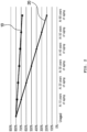
- FIG. 2 is a graph illustrating the age state of each of a heated cable and a non-heated cable according to an embodiment.
- the age state of each of the heated cable and the non-heated cable may be derived by measuring the elongation at break (EAB) of each power cable.
- the elongation at break over time may be derived for each temperature of the power cable. That is, among power cables, when comparing the elongation at break 20 of the heated cable having a temperature increased due to the application of power, and the elongation at break 10 of the non-heated cable to which no power is applied, the elongation at break 20 of the heated cable having the temperature increased due to the application of power decreases rapidly over time, compared to the elongation at break 10 of the non-heated cable to which no power is applied.
- the rapid decrease of the elongation at break 20 of the heated cable indicates that as a temperature thereof increases, an aging rate thereof increases, and it is possible to more precisely observe the age state of a power cable whose age state is to be monitored by considering heating caused by the application of power.
- the temperature of the power cable may be 70°C to 110°C for the heated cable and 20°C to 60°C for the non-heated cable. More preferably, the heated cable may be assumed to have 90°C, and the non-heated cable may be assumed to have 40°C to be shown in [Table 1], but the cables are not limited thereto, and the temperature of the heated cable may vary depending on the amount of power applied to each power cable.
- the elongation at break for each test cycle of the heated cable and the non-heated cable may be derived from Arrhenius equation, and the Arrhenius equation may be expressed as the following equation.
- k A e ⁇ E a RT
- Equation 1 k is a rate constant, T is an absolute temperature, A is an Arrhenius constant, Ea is activation energy, and R is a gas constant. That is, the more frequent collisions, the lower activation energy, and the higher a temperature, the more a reaction rate increases, and when the reaction rate increases, an aging rate becomes faster.
- the age state thereof when it is intended to monitor the age state of a power cable to which power has been applied for a long time, the age state thereof may be derived by measuring the elongation at break of a target power cable which is arranged at a location adjacent to the power cable whose age state is to be monitored and is exposed thereto for a predetermined period.
- the target power cable is a non-heated cable to which power is not applied, the elongation at break 10 of the non-heated cable of 40°C may be derived.
- the elongation at break 10 of the non-heated cable of 40°C When the elongation at break 10 of the non-heated cable of 40°C is 790%, the elongation at break 20 of the heated cable may be derived as 750% by being calculated from the relational expression, and the elongation at break 10 of the non-heated cable of 90°C may be determined to have aged for about 5 years.
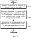
- FIG. 3 is a flowchart illustrating the method for monitoring the age state of a power cable according to an embodiment.
- the method for monitoring the age state of a power cable may include measuring at S100, generating data at S300, and deriving an age state at S500.
- the measuring unit 100 measures the elongation at break of at least one power cable.
- the data generation unit 300 In the generating of data at S300, the data generation unit 300 generates the relational expression by using the elongation at break of each of the heated cable to which a voltage is applied to raise a temperature thereof and the non-heated cable to which no voltage is applied among the measured power cables.
- a graph showing a change in an age state over time may be generated.
- the age state derivation unit 500 calculates the elongation at break of the target power cable whose age state is to be monitored by using the relational expression and derives the age state of the target power cable.
- the elongation at break 10 of the non-heated cable corresponding to the elongation at break of the target power cable may be derived, and the derived elongation at break 10 of the non-heated cable may be calculated by using the relational expression to derive the elongation at break 20 of the heated cable.
Landscapes
- Physics & Mathematics (AREA)
- General Physics & Mathematics (AREA)
- Engineering & Computer Science (AREA)
- Aviation & Aerospace Engineering (AREA)
- Mathematical Physics (AREA)
- Theoretical Computer Science (AREA)
- Testing Of Short-Circuits, Discontinuities, Leakage, Or Incorrect Line Connections (AREA)
- Electric Cable Installation (AREA)
Abstract
Description
- The present disclosure relates to a system and a method for monitoring the age state of a cable, and to a technology that considers self-heating of a power cable to monitor the age state of the cable.
- Power cables are used to transmit power from power plants to homes and buildings, and aging evaluation thereof is required to be performed periodically to minimize power loss due to resistance depending on the age states of the cables.
- Cable deposit is used as a method of cable aging condition monitoring to predict and evaluate the aging condition of cables.
- Cable deposit is a method of placing a cable specimen at the same location as a cable whose condition is to be monitored, making the cable specimen to be in the same condition as an actual aging condition of a cable in the field, recovering the specimen after a predetermined period of time, and measuring an aging condition thereof in a laboratory.
- However, monitoring an aging condition by cable deposit does not consider an Ohm heating effect caused by cable resistance generated in power cables, etc., so there is a problem in that measurement results are unreliable.
- To solve this problem, a method for monitoring the aging condition of a cable that considers self-heating thereof due to resistance of the cable is proposed.
- [Patent Document]
Korean Patent No. 10-0880440 (2009.01.29 - The present disclosure may provide a system and a method for monitoring the age state of a cable, in which an age state due to self-heating is able to be monitored by power applied to a power cable.
- According to an aspect of the present disclosure, a system for monitoring an age state of a power cable includes a measuring unit configured to measure elongation at break of at least one power cable, a data generation unit configured to generate a relational expression by using elongation at break of each of a heated cable to which a voltage is applied to raise a temperature thereof and a non-heated cable to which no voltage is applied, among the measured power cables, and an age state derivation unit configured to derive an age state of a target power cable by calculating elongation at break of the target power cable whose age state is to be monitored by using the relational expression.
- Preferably, the target power cable may be a non-heated cable exposed for a predetermined period of time to a location adjacent to a power cable to which a voltage is applied.
- Preferably, the data generation unit may generate a graph showing a change in an age state over time by using the elongation at break of each of the heated cable and the non-heated cable.
- Preferably, the age state derivation unit may derive an aging rate according to a temperature of the heated cable and a temperature of the non-heated cable.
- Preferably, the age state derivation unit may derive elongation at break of a non-heated cable corresponding to the elongation at break of the target power cable and calculate the derived elongation at break of the non-heated cable by using the relational expression to derive elongation at break of a heated cable.
- Preferably, the heated cable may be a power cable with a temperature of 70°C to 110°C, and the non-heated cable may be a power cable with a temperature of 20°C to 60°C.
- Preferably, the age state may be derived in any one unit of seconds, minutes, hours, days, months, and years.
- According to another aspect of the present disclosure, a method for monitoring the age state of a power cable includes measuring, by a measuring unit, elongation at break of at least one power cable, generating data by a data generation unit generating a relational expression by using elongation at break of each of a heated cable to which a voltage is applied to raise a temperature thereof and a non-heated cable to which no voltage is applied, among the measured power cables, and deriving, by an age state derivation unit, an age state of a target power cable by calculating elongation at break of the target power cable whose age state is to be monitored by using the relational expression.
- According to the present disclosure, it is possible to verify the age state of a power cable quickly and efficiently, and to improve the reliability of the age state of the power cable.
-
-
FIG. 1 is a configuration diagram of the system for monitoring the age state of a power cable according to an embodiment. -
FIG. 2 is a graph illustrating the age state of each of a heated cable and a non-heated cable according to an embodiment. -
FIG. 3 is a flowchart illustrating a method for monitoring the age state of a power cable according to an embodiment. - Hereinafter, a system and a method for monitoring the age state of a cable according to the present disclosure will be described in detail with reference to the accompanying drawings. In this process, the thickness of lines or sizes of components shown in the drawings may be exaggerated for clarity and convenience of explanation. In addition, terms to be described below are terms defined in consideration of functions in the present disclosure, and may vary depending on an operator's intention or practice. Therefore, definitions of these terms should be made on the basis of contents throughout this specification.
- The purpose and effect of the present disclosure may be naturally understood or made clearer by the description below, and the purpose and effect of the present disclosure are not limited to the description below. Additionally, when explaining the present disclosure, when it is determined that a detailed description of the publicly known technology related to the present disclosure may unnecessarily obscure the gist of the present disclosure, detailed description thereof will be omitted.
-
FIG. 1 is a configuration diagram of the system for monitoring the age state of a power cable according to an embodiment. - As illustrated in
FIG. 1 , the system for monitoring the age state of a power cable according to the embodiment may include ameasuring unit 100, adata generation unit 300, and an agestate derivation unit 500. - The
measuring unit 100 measures the elongation at break of at least one power cable. - The
data generation unit 300 generates a relational expression by using the elongation at break of each of a heated cable to which a voltage is applied to raise a temperature thereof and a non-heated cable to which no voltage is applied among the measured power cables. - Here, the
data generation unit 300 may generate a graph showing a change in an age state over time by using the elongation at break of each of the heated cable and the non-heated cable. - The age
state derivation unit 500 derives the age state of a target power cable by calculating the elongation at break of the target power cable whose age state is to be monitored by using the relational expression. - Here, the target power cable may be a non-heated cable exposed for a predetermined period of time to a location adjacent to a power cable to which a voltage is applied.
- In addition, the age
state derivation unit 500 may derive an aging rate according to the temperature of the heated cable and the temperature of the non-heated cable. - The age
state derivation unit 500 may derive the elongation atbreak 10 of the non-heated cable corresponding to the elongation at break of the target power cable, and may calculate the derived elongation atbreak 10 of the non-heated cable by using the relational expression to derive the elongation atbreak 20 of the heated cable. - In this case, the heated cable may be a power cable with a temperature of 70°C to 110°C, and the non-heated cable may be a power cable with a temperature of 20°C to 60°C.
- The age state may be derived in any one unit of seconds, minutes, hours, days, months, and years.
-
FIG. 2 is a graph illustrating the age state of each of a heated cable and a non-heated cable according to an embodiment. - As illustrated in
FIG. 2 , the age state of each of the heated cable and the non-heated cable according to an embodiment may be derived by measuring the elongation at break (EAB) of each power cable. Here, the elongation at break over time may be derived for each temperature of the power cable. That is, among power cables, when comparing the elongation atbreak 20 of the heated cable having a temperature increased due to the application of power, and the elongation atbreak 10 of the non-heated cable to which no power is applied, the elongation atbreak 20 of the heated cable having the temperature increased due to the application of power decreases rapidly over time, compared to the elongation atbreak 10 of the non-heated cable to which no power is applied. - The rapid decrease of the elongation at
break 20 of the heated cable indicates that as a temperature thereof increases, an aging rate thereof increases, and it is possible to more precisely observe the age state of a power cable whose age state is to be monitored by considering heating caused by the application of power. - In this case, the temperature of the power cable may be 70°C to 110°C for the heated cable and 20°C to 60°C for the non-heated cable. More preferably, the heated cable may be assumed to have 90°C, and the non-heated cable may be assumed to have 40°C to be shown in [Table 1], but the cables are not limited thereto, and the temperature of the heated cable may vary depending on the amount of power applied to each power cable.
[Table 1] EAB Unaged At 10 years At 20 years At 30 years At 40 years At 50 years At 60 years of aging of aging of aging of aging of aging of aging Heated cable (90°C ) 800% 700% 600% 500% 400% 300% 200% Non-heated cable (40°C ) 800% 780% 760% 740% 720% 700% 680% - Here, the elongation at break for each test cycle of the heated cable and the non-heated cable may be derived from Arrhenius equation, and the Arrhenius equation may be expressed as the following equation.
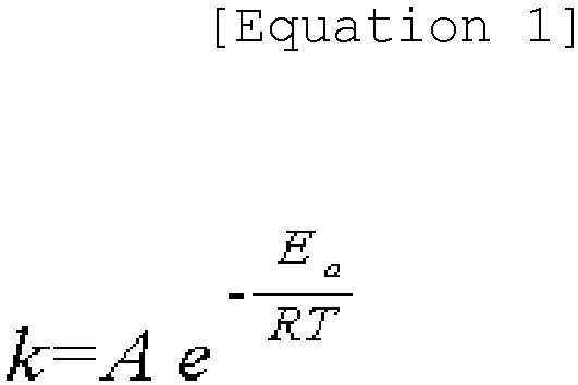
- In Equation 1, k is a rate constant, T is an absolute temperature, A is an Arrhenius constant, Ea is activation energy, and R is a gas constant. That is, the more frequent collisions, the lower activation energy, and the higher a temperature, the more a reaction rate increases, and when the reaction rate increases, an aging rate becomes faster.
- That is, when it is intended to monitor the age state of a power cable to which power has been applied for a long time, the age state thereof may be derived by measuring the elongation at break of a target power cable which is arranged at a location adjacent to the power cable whose age state is to be monitored and is exposed thereto for a predetermined period. In this case, since the target power cable is a non-heated cable to which power is not applied, the elongation at
break 10 of the non-heated cable of 40°C may be derived. - When the elongation at
break 10 of the non-heated cable of 40°C is 790%, the elongation atbreak 20 of the heated cable may be derived as 750% by being calculated from the relational expression, and the elongation atbreak 10 of the non-heated cable of 90°C may be determined to have aged for about 5 years. -
FIG. 3 is a flowchart illustrating the method for monitoring the age state of a power cable according to an embodiment. - As illustrated in
FIG. 3 , the method for monitoring the age state of a power cable according to an embodiment may include measuring at S100, generating data at S300, and deriving an age state at S500. - In the measuring at S100, the
measuring unit 100 measures the elongation at break of at least one power cable. - In the generating of data at S300, the
data generation unit 300 generates the relational expression by using the elongation at break of each of the heated cable to which a voltage is applied to raise a temperature thereof and the non-heated cable to which no voltage is applied among the measured power cables. - Here, in the generating of data at S300, by using the elongation at break measured from each of the heated cable and the non-heated cable, a graph showing a change in an age state over time may be generated.
- In the deriving of an age state at S500, the age
state derivation unit 500 calculates the elongation at break of the target power cable whose age state is to be monitored by using the relational expression and derives the age state of the target power cable. - Here, in the deriving of an age state at S500, the elongation at
break 10 of the non-heated cable corresponding to the elongation at break of the target power cable may be derived, and the derived elongation atbreak 10 of the non-heated cable may be calculated by using the relational expression to derive the elongation atbreak 20 of the heated cable. - Although the present disclosure has been described in detail through representative embodiments above, those skilled in the art will understand that various modifications may be made to the above-described embodiments without departing from the scope of the present disclosure. Therefore, the scope of rights of the present disclosure should not be limited to the described embodiments, but should be determined not only by the claims to be described later, but also by all changes or modified forms derived from concepts equivalent to the claims.
-
- 100: Measuring unit 300: Data generation unit
- 500: Age state derivation unit
- 10: Elongation at break of a non-heated cable 20: Elongation at break of a heated cable
Claims (8)
- A system for monitoring an age state of a power cable, the system comprising:a measuring unit configured to measure elongation at break of at least one power cable;a data generation unit configured to generate a relational expression by using elongation at break of each of a heated cable to which a voltage is applied to raise a temperature thereof and a non-heated cable to which no voltage is applied, among the measured power cables; andan age state derivation unit configured to derive an age state of a target power cable by calculating elongation at break of the target power cable whose age state is to be monitored by using the relational expression.
- The system of claim 1, wherein the target power cable is a non-heated cable exposed for a predetermined period of time to a location adjacent to a power cable to which a voltage is applied.
- The system of claim 1, wherein the data generation unit generates a graph showing a change in an age state over time by using the elongation at break of each of the heated cable and the non-heated cable.
- The system of claim 1, wherein the age state derivation unit derives an aging rate according to a temperature of the heated cable and a temperature of the non-heated cable.
- The system of claim 1, wherein the age state derivation unit derives elongation at break of a non-heated cable corresponding to the elongation at break of the target power cable and calculates the derived elongation at break of the non-heated cable by using the relational expression to derive elongation at break of a heated cable.
- The system of claim 1, wherein the heated cable is a power cable with a temperature of 70°C to 110°C, and the non-heated cable is a power cable with a temperature of 20°C to 60°C.
- The system of claim 1, wherein the age state is derived in any one unit of seconds, minutes, hours, days, months, and years.
- A method for monitoring an age state of a power cable, the method comprising:measuring, by a measuring unit, elongation at break of at least one power cable;generating data by a data generation unit generating a relational expression by using elongation at break of each of a heated cable to which a voltage is applied to raise a temperature thereof and a non-heated cable to which no voltage is applied, among the measured power cables; andderiving, by an age state derivation unit, an age state of a target power cable by calculating elongation at break of the target power cable whose age state is to be monitored by using the relational expression.
Applications Claiming Priority (2)
| Application Number | Priority Date | Filing Date | Title |
|---|---|---|---|
| KR1020220059498A KR20230159999A (en) | 2022-05-16 | 2022-05-16 | A system and method for monitoring the aging state of a power cable |
| PCT/KR2023/006513 WO2023224328A1 (en) | 2022-05-16 | 2023-05-12 | System and method for monitoring aging state of power cable |
Publications (2)
| Publication Number | Publication Date |
|---|---|
| EP4528294A1 true EP4528294A1 (en) | 2025-03-26 |
| EP4528294A4 EP4528294A4 (en) | 2026-04-22 |
Family
ID=88835766
Family Applications (1)
| Application Number | Title | Priority Date | Filing Date |
|---|---|---|---|
| EP23807848.9A Pending EP4528294A4 (en) | 2022-05-16 | 2023-05-12 | SYSTEM AND METHOD FOR MONITORING THE AGING STATE OF A POWER CABLE |
Country Status (4)
| Country | Link |
|---|---|
| US (1) | US20250067820A1 (en) |
| EP (1) | EP4528294A4 (en) |
| KR (1) | KR20230159999A (en) |
| WO (1) | WO2023224328A1 (en) |
Family Cites Families (11)
| Publication number | Priority date | Publication date | Assignee | Title |
|---|---|---|---|---|
| KR100880440B1 (en) | 2008-10-31 | 2009-01-29 | 주식회사 아이파워 | Power cable monitoring device and method of switchboard |
| KR20120008123A (en) * | 2010-07-16 | 2012-01-30 | 한국전기연구원 | Nondestructive Life Diagnosis Method of Aged Transmission Lines |
| KR101161776B1 (en) * | 2010-09-03 | 2012-07-03 | 한국전력공사 | Device and method of degradation diagnosis for power cable |
| US9647454B2 (en) * | 2011-08-31 | 2017-05-09 | Aclara Technologies Llc | Methods and apparatus for determining conditions of power lines |
| TW201504637A (en) * | 2013-07-23 | 2015-02-01 | Iner Aec Executive Yuan | Method for evaluating cable aging and deterioration by using slice sampling |
| CN104793111B (en) * | 2015-03-31 | 2017-11-07 | 华南理工大学 | Based on reason, change, the insulated cable residual life comprehensive estimation methods of electrical characteristics |
| KR20180127369A (en) * | 2016-03-28 | 2018-11-28 | 니폰 제온 가부시키가이샤 | A vinyl chloride resin composition, a vinyl chloride resin molded article, and a laminate |
| CN108918989A (en) * | 2018-04-28 | 2018-11-30 | 国网上海市电力公司 | A kind of military service cable residue lifetime estimation method based on multi-parameter |
| CN112485617B (en) * | 2020-11-27 | 2022-03-01 | 广东电网有限责任公司电力科学研究院 | Method and device for evaluating insulation aging state of cable |
| CN113588452B (en) * | 2021-07-30 | 2023-10-27 | 国网青海省电力公司信息通信公司 | Cable life prediction method and device and processor and storage medium |
| CN114184906B (en) * | 2021-11-08 | 2022-07-08 | 西南交通大学 | Crosslinked polyethylene cable insulation state evaluation method based on multi-scale aging factors |
-
2022
- 2022-05-16 KR KR1020220059498A patent/KR20230159999A/en not_active Ceased
-
2023
- 2023-05-12 WO PCT/KR2023/006513 patent/WO2023224328A1/en not_active Ceased
- 2023-05-12 EP EP23807848.9A patent/EP4528294A4/en active Pending
- 2023-05-12 US US18/723,171 patent/US20250067820A1/en active Pending
Also Published As
| Publication number | Publication date |
|---|---|
| KR20230159999A (en) | 2023-11-23 |
| WO2023224328A1 (en) | 2023-11-23 |
| EP4528294A4 (en) | 2026-04-22 |
| US20250067820A1 (en) | 2025-02-27 |
Similar Documents
| Publication | Publication Date | Title |
|---|---|---|
| Gillen et al. | Lifetime predictions for semi-crystalline cable insulation materials: I. Mechanical properties and oxygen consumption measurements on EPR materials | |
| KR100948035B1 (en) | Method of obtaining true strain-stress curve for high strain using tensile test and finite element method and tensile tester using the same | |
| EP2423664A2 (en) | Fatigue life estimation method and system | |
| EP2356425B1 (en) | Portable polymer tester | |
| JP2001141683A (en) | Method and apparatus for monitoring crack | |
| CN106198655A (en) | A Matrix Calculation Method for Detection of SF6 Decomposition Gas by Electrochemical Sensor | |
| DE102012019657B3 (en) | A method for determining a thermal transport size and a flow velocity in a flowing medium and thermal transport size measuring arrangement | |
| CN105091923B (en) | Method for operating measurement point | |
| US20250067820A1 (en) | System and method for monitoring aging state of power cable | |
| US20230278464A1 (en) | Method for Determining the Respective Temperature of Several Battery Cells of a Vehicle Battery Via Extrapolation of a Measured Temperature; Control Device and Vehicle Battery | |
| KR102164784B1 (en) | Life test method for thermoelectric module | |
| Moser et al. | Fatigue of copper films subjected to high-strain rate thermo-mechanical pulsing | |
| CN111209702A (en) | A method and device for benchmarking strength simulation and test of rail train body | |
| CN112816791A (en) | Cable insulation material activation energy measuring method and device based on dielectric spectrum | |
| Ozhikenov et al. | Development of technologies, methods and devices of the functional diagnostics of microelectronic sensors parts and components | |
| EP1771743B1 (en) | Method for determining time to failure of submicron metal interconnects | |
| CN109359375B (en) | Data product storage life prediction method | |
| WO2010101006A1 (en) | Method and device for determining specific heat capacity and semispherical total emissivity of conductive sample | |
| CN108227673A (en) | A kind of appraisal procedure for predicting the stopping sliding door controller service life | |
| CN116343968B (en) | A method and apparatus for obtaining the SN curve of solder joint material | |
| JP3196688B2 (en) | Corrosion monitoring method and apparatus | |
| US8232809B2 (en) | Determining critical current density for interconnect | |
| EP2682049A2 (en) | Method for calculating a thermal protection factor | |
| KR101145856B1 (en) | Measurement device of crack length and measuring method thereof | |
| JP4068549B2 (en) | Method and system for evaluating crack growth characteristics |
Legal Events
| Date | Code | Title | Description |
|---|---|---|---|
| STAA | Information on the status of an ep patent application or granted ep patent |
Free format text: STATUS: THE INTERNATIONAL PUBLICATION HAS BEEN MADE |
|
| PUAI | Public reference made under article 153(3) epc to a published international application that has entered the european phase |
Free format text: ORIGINAL CODE: 0009012 |
|
| STAA | Information on the status of an ep patent application or granted ep patent |
Free format text: STATUS: REQUEST FOR EXAMINATION WAS MADE |
|
| 17P | Request for examination filed |
Effective date: 20240613 |
|
| AK | Designated contracting states |
Kind code of ref document: A1 Designated state(s): AL AT BE BG CH CY CZ DE DK EE ES FI FR GB GR HR HU IE IS IT LI LT LU LV MC ME MK MT NL NO PL PT RO RS SE SI SK SM TR |
|
| DAV | Request for validation of the european patent (deleted) | ||
| DAX | Request for extension of the european patent (deleted) | ||
| A4 | Supplementary search report drawn up and despatched |
Effective date: 20260320 |
|
| RIC1 | Information provided on ipc code assigned before grant |
Ipc: G01R 31/08 20200101AFI20260316BHEP Ipc: G01R 31/58 20200101ALI20260316BHEP Ipc: H05B 3/56 20060101ALI20260316BHEP Ipc: G01M 5/00 20060101ALI20260316BHEP |