EP4528183A2 - Staged expansion system and method - Google Patents
Staged expansion system and method Download PDFInfo
- Publication number
- EP4528183A2 EP4528183A2 EP24211270.4A EP24211270A EP4528183A2 EP 4528183 A2 EP4528183 A2 EP 4528183A2 EP 24211270 A EP24211270 A EP 24211270A EP 4528183 A2 EP4528183 A2 EP 4528183A2
- Authority
- EP
- European Patent Office
- Prior art keywords
- heat exchanger
- refrigeration system
- evaporator
- upstream
- expansion device
- Prior art date
- Legal status (The legal status is an assumption and is not a legal conclusion. Google has not performed a legal analysis and makes no representation as to the accuracy of the status listed.)
- Withdrawn
Links
Images
Classifications
-
- F—MECHANICAL ENGINEERING; LIGHTING; HEATING; WEAPONS; BLASTING
- F25—REFRIGERATION OR COOLING; COMBINED HEATING AND REFRIGERATION SYSTEMS; HEAT PUMP SYSTEMS; MANUFACTURE OR STORAGE OF ICE; LIQUEFACTION SOLIDIFICATION OF GASES
- F25B—REFRIGERATION MACHINES, PLANTS OR SYSTEMS; COMBINED HEATING AND REFRIGERATION SYSTEMS; HEAT PUMP SYSTEMS
- F25B40/00—Subcoolers, desuperheaters or superheaters
- F25B40/02—Subcoolers
-
- F—MECHANICAL ENGINEERING; LIGHTING; HEATING; WEAPONS; BLASTING
- F25—REFRIGERATION OR COOLING; COMBINED HEATING AND REFRIGERATION SYSTEMS; HEAT PUMP SYSTEMS; MANUFACTURE OR STORAGE OF ICE; LIQUEFACTION SOLIDIFICATION OF GASES
- F25B—REFRIGERATION MACHINES, PLANTS OR SYSTEMS; COMBINED HEATING AND REFRIGERATION SYSTEMS; HEAT PUMP SYSTEMS
- F25B40/00—Subcoolers, desuperheaters or superheaters
-
- F—MECHANICAL ENGINEERING; LIGHTING; HEATING; WEAPONS; BLASTING
- F25—REFRIGERATION OR COOLING; COMBINED HEATING AND REFRIGERATION SYSTEMS; HEAT PUMP SYSTEMS; MANUFACTURE OR STORAGE OF ICE; LIQUEFACTION SOLIDIFICATION OF GASES
- F25B—REFRIGERATION MACHINES, PLANTS OR SYSTEMS; COMBINED HEATING AND REFRIGERATION SYSTEMS; HEAT PUMP SYSTEMS
- F25B41/00—Fluid-circulation arrangements
- F25B41/20—Disposition of valves, e.g. of on-off valves or flow control valves
- F25B41/22—Disposition of valves, e.g. of on-off valves or flow control valves between evaporator and compressor
-
- F—MECHANICAL ENGINEERING; LIGHTING; HEATING; WEAPONS; BLASTING
- F25—REFRIGERATION OR COOLING; COMBINED HEATING AND REFRIGERATION SYSTEMS; HEAT PUMP SYSTEMS; MANUFACTURE OR STORAGE OF ICE; LIQUEFACTION SOLIDIFICATION OF GASES
- F25B—REFRIGERATION MACHINES, PLANTS OR SYSTEMS; COMBINED HEATING AND REFRIGERATION SYSTEMS; HEAT PUMP SYSTEMS
- F25B41/00—Fluid-circulation arrangements
- F25B41/30—Expansion means; Dispositions thereof
- F25B41/39—Dispositions with two or more expansion means arranged in series, i.e. multi-stage expansion, on a refrigerant line leading to the same evaporator
-
- B—PERFORMING OPERATIONS; TRANSPORTING
- B60—VEHICLES IN GENERAL
- B60P—VEHICLES ADAPTED FOR LOAD TRANSPORTATION OR TO TRANSPORT, TO CARRY, OR TO COMPRISE SPECIAL LOADS OR OBJECTS
- B60P3/00—Vehicles adapted to transport, to carry or to comprise special loads or objects
- B60P3/20—Refrigerated goods vehicles
-
- F25B2327/001—
-
- F—MECHANICAL ENGINEERING; LIGHTING; HEATING; WEAPONS; BLASTING
- F25—REFRIGERATION OR COOLING; COMBINED HEATING AND REFRIGERATION SYSTEMS; HEAT PUMP SYSTEMS; MANUFACTURE OR STORAGE OF ICE; LIQUEFACTION SOLIDIFICATION OF GASES
- F25B—REFRIGERATION MACHINES, PLANTS OR SYSTEMS; COMBINED HEATING AND REFRIGERATION SYSTEMS; HEAT PUMP SYSTEMS
- F25B2341/00—Details of ejectors not being used as compression device; Details of flow restrictors or expansion valves
- F25B2341/06—Details of flow restrictors or expansion valves
- F25B2341/068—Expansion valves combined with a sensor
- F25B2341/0683—Expansion valves combined with a sensor the sensor is disposed in the suction line and influenced by the temperature or the pressure of the suction gas
-
- F—MECHANICAL ENGINEERING; LIGHTING; HEATING; WEAPONS; BLASTING
- F25—REFRIGERATION OR COOLING; COMBINED HEATING AND REFRIGERATION SYSTEMS; HEAT PUMP SYSTEMS; MANUFACTURE OR STORAGE OF ICE; LIQUEFACTION SOLIDIFICATION OF GASES
- F25B—REFRIGERATION MACHINES, PLANTS OR SYSTEMS; COMBINED HEATING AND REFRIGERATION SYSTEMS; HEAT PUMP SYSTEMS
- F25B2600/00—Control issues
- F25B2600/02—Compressor control
- F25B2600/027—Compressor control by controlling pressure
- F25B2600/0272—Compressor control by controlling pressure the suction pressure
Definitions
- the subject matter disclosed herein relates to refrigeration systems and, more specifically, to transportation refrigeration systems.
- Temperature controlled cargo containers such as refrigerated trailers, are commonly used to transport food products and other temperature sensitive products.
- a refrigerated trailer typically includes a refrigeration unit generally mounted on the front wall of the trailer with a portion protruding into the interior of the trailer.
- a fuel-burning engine may be used to drive a compressor of the refrigeration system.
- a refrigeration system in one aspect, includes a compressor configured to compress a refrigerant, a condenser, and an evaporator.
- a heat exchanger is disposed downstream of the condenser and upstream of the evaporator, and disposed downstream of the evaporator and upstream of the compressor, the heat exchanger configured to facilitate heat exchange between the refrigerant supplied from the condenser and the refrigerant supplied from the evaporator.
- a first expansion device is disposed downstream of the heat exchanger and upstream of the evaporator, and a second expansion device is disposed downstream of the condenser and upstream of the heat exchanger. The second expansion device is configured to cool the refrigerant passing therethrough to cool the refrigerant in the heat exchanger supplied from the evaporator to the compressor.
- further embodiments may include: wherein the heat exchanger is a liquid suction heat exchanger; wherein the heat exchanger is a brazed plate heat exchanger; wherein the refrigeration system is a transportation refrigeration system configured to thermally condition a cargo container; a receiver disposed downstream of the condenser and upstream of the second expansion device; a subcooler disposed downstream of the receiver and upstream of the second expansion device; an accumulator disposed downstream of the heat exchanger and the evaporator, and upstream of the compressor; a suction modulating valve disposed downstream of the heat exchanger and the evaporator, and upstream of the compressor; and/or a power generation system including an engine fluidly coupled to a radiator, and a cooling loop configured to supply cooling air to the condenser and the radiator to absorb heat therefrom.
- the refrigeration system is a transportation refrigeration system configured to thermally condition a cargo container
- a receiver disposed downstream of the condenser and upstream of the second expansion device
- a subcooler disposed downstream of the
- a transportation refrigeration system configured to provide thermal conditioning for a container.
- the system includes a compressor configured to compress a refrigerant, a condenser, and an evaporator.
- a heat exchanger is disposed downstream of the condenser and upstream of the evaporator, and disposed downstream of the evaporator and upstream of the compressor, the heat exchanger configured to facilitate heat exchange between the refrigerant supplied from the condenser and the refrigerant supplied from the evaporator.
- a first expansion device is disposed downstream of the heat exchanger and upstream of the evaporator, and a second expansion device is disposed downstream of the condenser and upstream of the heat exchanger. The second expansion device is configured to cool the refrigerant passing therethrough to cool the refrigerant in the heat exchanger supplied from the evaporator to the compressor.
- further embodiments may include: wherein the heat exchanger is a liquid suction heat exchanger; wherein the heat exchanger is a brazed plate heat exchanger; a receiver disposed downstream of the condenser and upstream of the second expansion device; a subcooler disposed downstream of the receiver and upstream of the second expansion device; an accumulator disposed downstream of the heat exchanger and the evaporator, and upstream of the compressor; a suction modulating valve disposed downstream of the accumulator and upstream of the compressor; and/or a power generation system including an engine fluidly coupled to a radiator, and a cooling loop configured to supply cooling air to the condenser and the radiator to absorb heat therefrom.
- a method of assembling a refrigeration system includes providing a compressor configured to compress a refrigerant, providing a condenser, and providing an evaporator.
- the method further includes providing a heat exchanger disposed downstream of the condenser and upstream of the evaporator, and disposed downstream of the evaporator and upstream of the compressor, the heat exchanger configured to facilitate heat exchange between the refrigerant supplied from the condenser and the refrigerant supplied from the evaporator, providing a first expansion device disposed downstream of the heat exchanger and upstream of the evaporator, and providing a second expansion device disposed downstream of the condenser and upstream of the heat exchanger, the second expansion device configured to cool the refrigerant passing therethrough to cool the refrigerant in the heat exchanger supplied form the evaporator to the compressor.
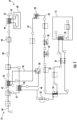
- FIG. 1 is a schematic view of an exemplary refrigeration system.
- FIG. 1 illustrates a refrigeration system 10.
- refrigeration system 10 is operably associated with a temperature controlled cargo container 12 configured to maintain a cargo located inside cargo container 12 at a selected temperature through the use of refrigeration system 10.
- the cargo container may be utilized to transport cargo via, for example, a truck, a train or a ship.
- Transportation refrigeration applications are distinct from other applications due to their wide range of operating conditions.
- the ambient temperature may vary from 148 °F to -20 °F
- the cargo container may be set at a temperature between 100 °F and -20 °F.
- system 10 may be utilized in various other refrigeration applications.
- refrigeration system 10 may be powered by a power generation system 14, and a cooling loop 16 provides thermal heat exchange between refrigeration system 10 and power generation system 14.
- system 10 may be any suitable environment conditioning system.
- system 10 may be a cab air conditioning unit for a vehicle.
- system 10 may be a direct drive application, a container unit application, or other configuration.
- Refrigeration system 10 generally includes a compressor 20, a condenser 22, a main expansion device 24, and an evaporator 26. As illustrated in the exemplary embodiment, system 10 includes a receiver 28, a subcooler 30, an expansion device 32, a liquid suction heat exchanger 34, an accumulator 36, and a compressor pressure limiter (CPL) or suction modulating valve (SMV) 38. In other embodiments, system 10 may not include receiver 28, subcooler 30, and/or accumulator 36.
- CPL compressor pressure limiter
- SMV suction modulating valve
- Refrigeration system 10 is a closed loop system through which refrigerant is circulated in various states such as liquid and vapor. As such, a low temperature, low pressure superheated gas refrigerant is drawn into compressor 20 through a conduit 40 from evaporator 26. The refrigerant is compressed and the resulting high temperature, high pressure superheated gas is discharged from compressor 20 to condenser 22 through a conduit 42
- gaseous refrigerant is condensed into liquid as it gives up heat.
- the superheated gas refrigerant enters condenser 22 and is de-superheated, condensed, and sub-cooled through a heat exchanger process with air forced across condenser 22 by a condenser fan 44 (via a conduit 43) to absorb heat.
- a condenser fan 44 via a conduit 43
- water or other fluid may be used to absorb heat from condenser.
- the liquid refrigerant is discharged from condenser 22 and supplied through a conduit 46 via receiver 28 to subcooler 30.
- the refrigerant is further sub-cooled by air forced by condenser fan 44 (through a conduit 45) and is supplied through a conduit 48 to expansion device 32.
- subcooler 30 may be integrated into condenser 22.
- expansion device 32 is a modulation valve or an electronic expansion valve.
- Expansion device 32 is disposed upstream of liquid suction heat exchanger 34 in order to decrease the inlet temperature of heat exchanger 34.
- Refrigerant passing from evaporator 26 to compressor 20 via heat exchanger 34 is cooled by the refrigerant expanded in expansion device 32, which lowers the suction temperature and thus the discharge temperature of compressor 20.
- the discharge temperature of compressor 20 can be controlled and lowered with a minor impact on the cooling capacity performance of refrigeration system 10.
- system 10 may not include a liquid injection valve that may have a larger impact on system performance.
- Expansion device 32 may be selectively opened or closed to facilitate control of the compressor suction/discharge temperature.
- expansion device 32 may be in a fully open position. In contrast, if it is desirable to lower the compressor discharge temperature (e.g., during higher ambient temperatures), expansion device 32 may be placed in a partially open position. Refrigerant passing through expansion device 32 is subsequently supplied to heat exchanger 34.
- liquid suction heat exchanger 34 reduces heating of vaporized and/or vaporizing refrigerant from evaporator 26 against the liquid refrigerant expanded in expansion device 32.
- heat exchanger 34 may be a brazed plate heat exchanger.
- the warmed refrigerant is subsequently supplied from heat exchanger 34 to evaporator 26 through a conduit 50, by passing the refrigerant through metering or expansion device 24 (e.g., expansion valve), which converts the relatively higher temperature, high pressure sub-cooled liquid to a low temperature saturated liquid-vapor mixture.
- metering or expansion device 24 e.g., expansion valve
- the low temperature saturated liquid-vapor refrigerant mixture then enters evaporator 26 where it boils and changes states to a superheated gas as it absorbs the required heat of vaporization from air in the container (or other heat exchange fluid).
- the low pressure superheated gas then passes in heat exchange relation with heat exchanger 34, where heating is further reduced to decrease the suction temperature of compressor 20.
- the superheated gas is then drawn through accumulator 36 and SMV 38 into the inlet of compressor 20 and the cycle is repeated.
- power generation system 14 generally includes an engine 60 coupled to a fuel tank (not shown).
- a conduit 62 supplies coolant between engine 60 and a heat exchanger 64 (e.g., a radiator) to cool engine 60 during operation.
- system 10 may not include power generation system 14 (e.g., with a direct drive unit or a container unit without an engine).
- cooling loop 16 generally includes an air intake conduit 66 that supplies ambient or other cooling fluid to conduits 43, 45 via fan 44.
- Conduits 43, 45 may combine into a single conduit 68, and fan 44 subsequently forces air across heat exchanger 64 to absorb heat.
- the air heated by heat exchangers 22, 30, and 64 is subsequently vented to the atmosphere via a conduit 70.
- a first expansion device such as a modulation valve or an electronic expansion valve is disposed downstream of the condenser and upstream of a heat exchanger such as a liquid suction heat exchanger or a braze plate heat exchanger. After passing through the heat exchanger, the expanded refrigerant is subsequently passed through a second expansion device disposed downstream of the heat exchanger and upstream of an evaporator.
- the first expansion device decreases the refrigerant temperature of the heat exchanger, thereby reducing the compressor discharge temperature with little or no impact on the cooling capacity performance of the refrigeration system.
Landscapes
- Engineering & Computer Science (AREA)
- Physics & Mathematics (AREA)
- Mechanical Engineering (AREA)
- Thermal Sciences (AREA)
- General Engineering & Computer Science (AREA)
- Devices That Are Associated With Refrigeration Equipment (AREA)
- Compression-Type Refrigeration Machines With Reversible Cycles (AREA)
Abstract
Description
- The subject matter disclosed herein relates to refrigeration systems and, more specifically, to transportation refrigeration systems.
- Temperature controlled cargo containers, such as refrigerated trailers, are commonly used to transport food products and other temperature sensitive products. A refrigerated trailer typically includes a refrigeration unit generally mounted on the front wall of the trailer with a portion protruding into the interior of the trailer. In some known trailers, a fuel-burning engine may be used to drive a compressor of the refrigeration system.
- Due to refrigerant regulations for some refrigeration systems, replacement refrigerants may cause an increase in the discharge temperature of the refrigeration loop. This temperature increase may create performance issues during certain conditions such as, for example, high ambient conditions, which may require additional cooling of one or more system compressors.
- In one aspect, a refrigeration system is provided. The refrigeration system includes a compressor configured to compress a refrigerant, a condenser, and an evaporator. A heat exchanger is disposed downstream of the condenser and upstream of the evaporator, and disposed downstream of the evaporator and upstream of the compressor, the heat exchanger configured to facilitate heat exchange between the refrigerant supplied from the condenser and the refrigerant supplied from the evaporator. A first expansion device is disposed downstream of the heat exchanger and upstream of the evaporator, and a second expansion device is disposed downstream of the condenser and upstream of the heat exchanger. The second expansion device is configured to cool the refrigerant passing therethrough to cool the refrigerant in the heat exchanger supplied from the evaporator to the compressor.
- In addition to one or more of the features described above, or as an alternative, further embodiments may include: wherein the heat exchanger is a liquid suction heat exchanger; wherein the heat exchanger is a brazed plate heat exchanger; wherein the refrigeration system is a transportation refrigeration system configured to thermally condition a cargo container; a receiver disposed downstream of the condenser and upstream of the second expansion device; a subcooler disposed downstream of the receiver and upstream of the second expansion device; an accumulator disposed downstream of the heat exchanger and the evaporator, and upstream of the compressor; a suction modulating valve disposed downstream of the heat exchanger and the evaporator, and upstream of the compressor; and/or a power generation system including an engine fluidly coupled to a radiator, and a cooling loop configured to supply cooling air to the condenser and the radiator to absorb heat therefrom.
- In another aspect, a transportation refrigeration system configured to provide thermal conditioning for a container is provided. The system includes a compressor configured to compress a refrigerant, a condenser, and an evaporator. A heat exchanger is disposed downstream of the condenser and upstream of the evaporator, and disposed downstream of the evaporator and upstream of the compressor, the heat exchanger configured to facilitate heat exchange between the refrigerant supplied from the condenser and the refrigerant supplied from the evaporator. A first expansion device is disposed downstream of the heat exchanger and upstream of the evaporator, and a second expansion device is disposed downstream of the condenser and upstream of the heat exchanger. The second expansion device is configured to cool the refrigerant passing therethrough to cool the refrigerant in the heat exchanger supplied from the evaporator to the compressor.
- In addition to one or more of the features described above, or as an alternative, further embodiments may include: wherein the heat exchanger is a liquid suction heat exchanger; wherein the heat exchanger is a brazed plate heat exchanger; a receiver disposed downstream of the condenser and upstream of the second expansion device; a subcooler disposed downstream of the receiver and upstream of the second expansion device; an accumulator disposed downstream of the heat exchanger and the evaporator, and upstream of the compressor; a suction modulating valve disposed downstream of the accumulator and upstream of the compressor; and/or a power generation system including an engine fluidly coupled to a radiator, and a cooling loop configured to supply cooling air to the condenser and the radiator to absorb heat therefrom.
- In yet another aspect, a method of assembling a refrigeration system is provided. The method includes providing a compressor configured to compress a refrigerant, providing a condenser, and providing an evaporator. The method further includes providing a heat exchanger disposed downstream of the condenser and upstream of the evaporator, and disposed downstream of the evaporator and upstream of the compressor, the heat exchanger configured to facilitate heat exchange between the refrigerant supplied from the condenser and the refrigerant supplied from the evaporator, providing a first expansion device disposed downstream of the heat exchanger and upstream of the evaporator, and providing a second expansion device disposed downstream of the condenser and upstream of the heat exchanger, the second expansion device configured to cool the refrigerant passing therethrough to cool the refrigerant in the heat exchanger supplied form the evaporator to the compressor.
- The subject matter which is regarded as the invention is particularly pointed out and distinctly claimed in the claims at the conclusion of the specification. The foregoing and other features, and advantages of the invention are apparent from the following detailed description taken in conjunction with the accompanying drawings in which:
FIG. 1 is a schematic view of an exemplary refrigeration system. -
FIG. 1 illustrates a refrigeration system 10. In the exemplary embodiment, refrigeration system 10 is operably associated with a temperature controlledcargo container 12 configured to maintain a cargo located insidecargo container 12 at a selected temperature through the use of refrigeration system 10. The cargo container may be utilized to transport cargo via, for example, a truck, a train or a ship. Transportation refrigeration applications are distinct from other applications due to their wide range of operating conditions. For example, the ambient temperature may vary from 148 °F to -20 °F, and the cargo container may be set at a temperature between 100 °F and -20 °F. However, system 10 may be utilized in various other refrigeration applications. - In the exemplary embodiment, refrigeration system 10 may be powered by a
power generation system 14, and acooling loop 16 provides thermal heat exchange between refrigeration system 10 andpower generation system 14. Although described as a refrigeration system, system 10 may be any suitable environment conditioning system. For example, system 10 may be a cab air conditioning unit for a vehicle. In other embodiments, system 10 may be a direct drive application, a container unit application, or other configuration. - Refrigeration system 10 generally includes a
compressor 20, acondenser 22, amain expansion device 24, and anevaporator 26. As illustrated in the exemplary embodiment, system 10 includes areceiver 28, asubcooler 30, anexpansion device 32, a liquidsuction heat exchanger 34, anaccumulator 36, and a compressor pressure limiter (CPL) or suction modulating valve (SMV) 38. In other embodiments, system 10 may not includereceiver 28,subcooler 30, and/oraccumulator 36. - Refrigeration system 10 is a closed loop system through which refrigerant is circulated in various states such as liquid and vapor. As such, a low temperature, low pressure superheated gas refrigerant is drawn into
compressor 20 through aconduit 40 fromevaporator 26. The refrigerant is compressed and the resulting high temperature, high pressure superheated gas is discharged fromcompressor 20 to condenser 22 through aconduit 42 - In
condenser 22, gaseous refrigerant is condensed into liquid as it gives up heat. The superheated gas refrigerant enterscondenser 22 and is de-superheated, condensed, and sub-cooled through a heat exchanger process with air forced acrosscondenser 22 by a condenser fan 44 (via a conduit 43) to absorb heat. Alternatively, water or other fluid may be used to absorb heat from condenser. The liquid refrigerant is discharged fromcondenser 22 and supplied through aconduit 46 viareceiver 28 tosubcooler 30. The refrigerant is further sub-cooled by air forced by condenser fan 44 (through a conduit 45) and is supplied through aconduit 48 toexpansion device 32. In some embodiments,subcooler 30 may be integrated intocondenser 22. - In the exemplary embodiment,
expansion device 32 is a modulation valve or an electronic expansion valve.Expansion device 32 is disposed upstream of liquidsuction heat exchanger 34 in order to decrease the inlet temperature ofheat exchanger 34. Refrigerant passing fromevaporator 26 tocompressor 20 viaheat exchanger 34 is cooled by the refrigerant expanded inexpansion device 32, which lowers the suction temperature and thus the discharge temperature ofcompressor 20. As such, the discharge temperature ofcompressor 20 can be controlled and lowered with a minor impact on the cooling capacity performance of refrigeration system 10. Accordingly, system 10 may not include a liquid injection valve that may have a larger impact on system performance.Expansion device 32 may be selectively opened or closed to facilitate control of the compressor suction/discharge temperature. For example, if it is not desirable to lower the discharge temperature (e.g., during lower ambient temperatures),expansion device 32 may be in a fully open position. In contrast, if it is desirable to lower the compressor discharge temperature (e.g., during higher ambient temperatures),expansion device 32 may be placed in a partially open position. Refrigerant passing throughexpansion device 32 is subsequently supplied toheat exchanger 34. - In the exemplary embodiment, liquid
suction heat exchanger 34 reduces heating of vaporized and/or vaporizing refrigerant fromevaporator 26 against the liquid refrigerant expanded inexpansion device 32. In other embodiments,heat exchanger 34 may be a brazed plate heat exchanger. The warmed refrigerant is subsequently supplied fromheat exchanger 34 toevaporator 26 through aconduit 50, by passing the refrigerant through metering or expansion device 24 (e.g., expansion valve), which converts the relatively higher temperature, high pressure sub-cooled liquid to a low temperature saturated liquid-vapor mixture. - The low temperature saturated liquid-vapor refrigerant mixture then enters
evaporator 26 where it boils and changes states to a superheated gas as it absorbs the required heat of vaporization from air in the container (or other heat exchange fluid). The low pressure superheated gas then passes in heat exchange relation withheat exchanger 34, where heating is further reduced to decrease the suction temperature ofcompressor 20. The superheated gas is then drawn throughaccumulator 36 andSMV 38 into the inlet ofcompressor 20 and the cycle is repeated. - In the illustrated embodiment,
power generation system 14 generally includes anengine 60 coupled to a fuel tank (not shown). Aconduit 62 supplies coolant betweenengine 60 and a heat exchanger 64 (e.g., a radiator) to coolengine 60 during operation. In alternate embodiments, system 10 may not include power generation system 14 (e.g., with a direct drive unit or a container unit without an engine). - In the illustrated embodiment, cooling
loop 16 generally includes anair intake conduit 66 that supplies ambient or other cooling fluid toconduits fan 44.Conduits single conduit 68, andfan 44 subsequently forces air acrossheat exchanger 64 to absorb heat. The air heated byheat exchangers conduit 70. - Described herein are systems and methods for controlling suction/discharge temperature of a compressor in a refrigeration system. This may be required for system utilizing refrigerants such as R407F and R448A, which may result in higher compressor discharge temperatures in certain conditions. A first expansion device such as a modulation valve or an electronic expansion valve is disposed downstream of the condenser and upstream of a heat exchanger such as a liquid suction heat exchanger or a braze plate heat exchanger. After passing through the heat exchanger, the expanded refrigerant is subsequently passed through a second expansion device disposed downstream of the heat exchanger and upstream of an evaporator. The first expansion device decreases the refrigerant temperature of the heat exchanger, thereby reducing the compressor discharge temperature with little or no impact on the cooling capacity performance of the refrigeration system.
- While the invention has been described in detail in connection with only a limited number of embodiments, it should be readily understood that the invention is not limited to such disclosed embodiments. Rather, the invention can be modified to incorporate any number of variations, alterations, substitutions or equivalent arrangements not heretofore described, but which are commensurate with the spirit and scope of the invention. Additionally, while various embodiments of the invention have been described, it is to be understood that aspects of the invention may include only some of the described embodiments. Accordingly, the invention is not to be seen as limited by the foregoing description, but is only limited by the scope of the appended claims.
- The following clauses set out embodiments of the invention which may or may not presently be claimed, but which may form the basis for future amendment or a divisional application.
- 1. A refrigeration system comprising:
- a compressor configured to compress a refrigerant;
- a condenser;
- an evaporator;
- a heat exchanger disposed downstream of the condenser and upstream of the evaporator, and disposed downstream of the evaporator and upstream of the compressor, the heat exchanger configured to facilitate heat exchange between the refrigerant supplied from the condenser and the refrigerant supplied from the evaporator;
- a first expansion device disposed downstream of the heat exchanger and upstream of the evaporator; and
- a second expansion device disposed downstream of the condenser and upstream of the heat exchanger, the second expansion device configured to cool the refrigerant passing therethrough to cool the refrigerant in the heat exchanger supplied from the evaporator to the compressor.
- 2. The refrigeration system of clause 1, wherein the heat exchanger is a liquid suction heat exchanger.
- 3. The refrigeration system of clause 1, wherein the heat exchanger is a brazed plate heat exchanger.
- 4. The refrigeration system of clause 1, wherein the refrigeration system is a transportation refrigeration system configured to thermally condition a cargo container.
- 5. The refrigeration system of clause 1, further comprising a receiver disposed downstream of the condenser and upstream of the second expansion device.
- 6. The refrigeration system of clause 5, further comprising a subcooler disposed downstream of the receiver and upstream of the second expansion device.
- 7. The refrigeration system of clause 1, further comprising an accumulator disposed downstream of the heat exchanger and the evaporator, and upstream of the compressor.
- 8. The refrigeration system of clause 1, further comprising a suction modulating valve disposed downstream of the heat exchanger and the evaporator, and upstream of the compressor.
- 9. The refrigeration system of clause 1, further comprising:
- a power generation system including an engine fluidly coupled to a radiator; and
- a cooling loop configured to supply cooling air to the condenser and the radiator to absorb heat therefrom.
- 10. A transportation refrigeration system configured to provide thermal conditioning for a container, the system comprising:
- a compressor configured to compress a refrigerant;
- a condenser;
- an evaporator;
- a heat exchanger disposed downstream of the condenser and upstream of the evaporator, and disposed downstream of the evaporator and upstream of the compressor, the heat exchanger configured to facilitate heat exchange between the refrigerant supplied from the condenser and the refrigerant supplied from the evaporator;
- a first expansion device disposed downstream of the heat exchanger and upstream of the evaporator; and
- a second expansion device disposed downstream of the condenser and upstream of the heat exchanger, the second expansion device configured to cool the refrigerant passing therethrough to cool the refrigerant in the heat exchanger supplied from the evaporator to the compressor.
- 11. The transportation refrigeration system of clause 10, wherein the heat exchanger is a liquid suction heat exchanger.
- 12. The transportation refrigeration system of clause 10, wherein the heat exchanger is a brazed plate heat exchanger.
- 13. The transportation refrigeration system of clause 10, further comprising a receiver disposed downstream of the condenser and upstream of the second expansion device.
- 14. The transportation refrigeration system of clause 13, further comprising a subcooler disposed downstream of the receiver and upstream of the second expansion device.
- 15. The transportation refrigeration system of
clause 14, further comprising an accumulator disposed downstream of the heat exchanger and the evaporator, and upstream of the compressor. - 16. The transportation refrigeration system of clause 15, further comprising a suction modulating valve disposed downstream of the accumulator and upstream of the compressor.
- 17. The transportation refrigeration system of
clause 16, further comprising:- a power generation system including an engine fluidly coupled to a radiator; and
- a cooling loop configured to supply cooling air to the condenser and the radiator to absorb heat therefrom.
- 18. A method of assembling a refrigeration system, the method comprising:
- providing a compressor configured to compress a refrigerant;
- providing a condenser;
- providing an evaporator;
- providing a heat exchanger disposed downstream of the condenser and upstream of the evaporator, and disposed downstream of the evaporator and upstream of the compressor, the heat exchanger configured to facilitate heat exchange between the refrigerant supplied from the condenser and the refrigerant supplied from the evaporator;
- providing a first expansion device disposed downstream of the heat exchanger and upstream of the evaporator; and
- providing a second expansion device disposed downstream of the condenser and upstream of the heat exchanger, the second expansion device configured to cool the refrigerant passing therethrough to cool the refrigerant in the heat exchanger supplied form the evaporator to the compressor.
Claims (15)
- A refrigeration system (10) comprising:a compressor (20) configured to compress a refrigerant;a condenser (22);a cooling loop (16) comprising an air intake conduit (66) configured to supply ambient fluid to the condenser (22) via a fan (44);an evaporator (26), wherein the evaporator (26) is associated with a temperature controlled cargo container (12) and the refrigeration system (10) is configured to maintain cargo located inside the cargo container (12) at a selected temperature;a heat exchanger (34) disposed downstream of the condenser and upstream of the evaporator, and disposed downstream of the evaporator and upstream of the compressor, the heat exchanger configured to facilitate heat exchange between the refrigerant supplied from the condenser and the refrigerant supplied from the evaporator;a first expansion device (24) disposed downstream of the heat exchanger and upstream of the evaporator; anda second expansion device (32) disposed downstream of the condenser and upstream of the heat exchanger, the second expansion device configured to cool the refrigerant passing therethrough to cool the refrigerant in the heat exchanger supplied from the evaporator to the compressor, wherein all of the refrigerant passing through the second expansion device (32) is subsequently supplied to the heat exchanger (34).
- The refrigeration system of claim 1, wherein the heat exchanger is a liquid suction heat exchanger.
- The refrigeration system of claim 1 or 2, wherein the heat exchanger is a brazed plate heat exchanger.
- The refrigeration system of any of claims 1 to 3, further comprising a receiver (28) disposed downstream of the condenser and upstream of the second expansion device.
- The refrigeration system of claim 4, further comprising a subcooler (30) disposed downstream of the receiver and upstream of the second expansion device.
- The refrigeration system of any of claims 1 to 5, further comprising an accumulator (36) disposed downstream of the heat exchanger and the evaporator, and upstream of the compressor.
- The refrigeration system of any of claims 1 to 6, further comprising a suction modulating valve (38) disposed downstream of the heat exchanger and the evaporator, and upstream of the compressor.
- The refrigeration system of any of claims 1 to 7, further comprising:a power generation system (14) including an engine fluidly coupled to a radiator,wherein the cooling loop (16) is configured to supply cooling air to the condenser and the radiator to absorb heat therefrom.
- The refrigeration system of any of claims 1 to 8, wherein the second expansion device (32) is a modulation valve or an electronic expansion valve.
- A transportation refrigeration system configured to provide thermal conditioning for a container (12), the system comprising the refrigeration system of any previous claim.
- The transportation refrigeration system of claim 10, further comprising a receiver (28) disposed downstream of the condenser and upstream of the second expansion device and a subcooler (30) disposed downstream of the receiver and upstream of the second expansion device.
- The transportation refrigeration system of claim 11, further comprising an accumulator (36) disposed downstream of the heat exchanger and the evaporator, and upstream of the compressor, optionally
further comprising a suction modulating valve (38) disposed downstream of the accumulator and upstream of the compressor. - The transportation refrigeration system of any of claims 10 to 12, further comprising:a power generation system (14) including an engine (60) fluidly coupled to a radiator (64),wherein the cooling loop (16) is configured to supply cooling air to the condenser and the radiator to absorb heat therefrom.
- A method of operating the refrigeration system of any of claims 1 to 9, the method comprising:operating the second expansion device (32) to cool the refrigerant passing therethrough to cool the refrigerant in the heat exchanger (34) supplied from the evaporator (26) to the compressor (20), andoperating the refrigeration system such that all of the refrigerant passing through the second expansion device (32) is subsequently supplied to the heat exchanger (34).
- The method of claim 14, further comprising selectively opening or closing the second expansion device (32) to facilitate control of the compressor discharge temperature, wherein the second expansion device (32) can be in a fully open position or a partially open position wherein the compressor discharge temperature is lowered.
Priority Applications (1)
| Application Number | Priority Date | Filing Date | Title |
|---|---|---|---|
| EP24211270.4A EP4528183A3 (en) | 2015-05-15 | 2015-05-15 | Staged expansion system and method |
Applications Claiming Priority (3)
| Application Number | Priority Date | Filing Date | Title |
|---|---|---|---|
| PCT/IB2015/001113 WO2016185243A1 (en) | 2015-05-15 | 2015-05-15 | Staged expansion system and method |
| EP15771238.1A EP3295095A1 (en) | 2015-05-15 | 2015-05-15 | Staged expansion system and method |
| EP24211270.4A EP4528183A3 (en) | 2015-05-15 | 2015-05-15 | Staged expansion system and method |
Related Parent Applications (1)
| Application Number | Title | Priority Date | Filing Date |
|---|---|---|---|
| EP15771238.1A Division EP3295095A1 (en) | 2015-05-15 | 2015-05-15 | Staged expansion system and method |
Publications (2)
| Publication Number | Publication Date |
|---|---|
| EP4528183A2 true EP4528183A2 (en) | 2025-03-26 |
| EP4528183A3 EP4528183A3 (en) | 2025-05-14 |
Family
ID=54199893
Family Applications (2)
| Application Number | Title | Priority Date | Filing Date |
|---|---|---|---|
| EP15771238.1A Ceased EP3295095A1 (en) | 2015-05-15 | 2015-05-15 | Staged expansion system and method |
| EP24211270.4A Withdrawn EP4528183A3 (en) | 2015-05-15 | 2015-05-15 | Staged expansion system and method |
Family Applications Before (1)
| Application Number | Title | Priority Date | Filing Date |
|---|---|---|---|
| EP15771238.1A Ceased EP3295095A1 (en) | 2015-05-15 | 2015-05-15 | Staged expansion system and method |
Country Status (4)
| Country | Link |
|---|---|
| US (1) | US10473369B2 (en) |
| EP (2) | EP3295095A1 (en) |
| CN (1) | CN107624153B (en) |
| WO (1) | WO2016185243A1 (en) |
Families Citing this family (3)
| Publication number | Priority date | Publication date | Assignee | Title |
|---|---|---|---|---|
| GB2575980A (en) * | 2018-07-30 | 2020-02-05 | Linde Ag | High temperature superconductor refrigeration system |
| US10865698B1 (en) * | 2019-12-10 | 2020-12-15 | Ford Global Technologies, Llc | Method to reduce engine coolant temperature based on climate fan speed |
| US12140359B2 (en) | 2021-10-21 | 2024-11-12 | Copeland Lp | Climate control systems for use with high glide working fluids and methods for operation thereof |
Family Cites Families (31)
| Publication number | Priority date | Publication date | Assignee | Title |
|---|---|---|---|---|
| US3423951A (en) | 1967-07-17 | 1969-01-28 | Carrier Corp | Absorption refrigeration systems having solution-cooled absorbers |
| US4707996A (en) * | 1983-09-29 | 1987-11-24 | Vobach Arnold R | Chemically assisted mechanical refrigeration process |
| JPH0686976B2 (en) * | 1985-10-17 | 1994-11-02 | ダイキン工業株式会社 | Refrigeration equipment for containers |
| US5056329A (en) * | 1990-06-25 | 1991-10-15 | Battelle Memorial Institute | Heat pump systems |
| US5140827A (en) | 1991-05-14 | 1992-08-25 | Electric Power Research Institute, Inc. | Automatic refrigerant charge variation means |
| JPH09329375A (en) | 1996-06-10 | 1997-12-22 | Sanyo Electric Co Ltd | Replenishing/filling method of non-azeorope refrigerant and device thereof |
| US5784892A (en) | 1996-09-09 | 1998-07-28 | Electric Power Research Institute, Inc. | Refrigerant charge variation mechanism |
| JPH11142007A (en) * | 1997-11-06 | 1999-05-28 | Nippon Soken Inc | Refrigeration cycle |
| US6568198B1 (en) | 1999-09-24 | 2003-05-27 | Sanyo Electric Co., Ltd. | Multi-stage compression refrigerating device |
| DE10123830A1 (en) * | 2001-05-16 | 2002-11-28 | Bosch Gmbh Robert | Vehicle air conditioning system uses a heat pump action with the evaporator as the heat source, in the heating mode, for a rapid heating of the interior without loss and heating of the motor to its working temperature |
| US6679074B2 (en) * | 2001-07-31 | 2004-01-20 | Thermo King Corporation | Automatic switching refrigeration system |
| US6539735B1 (en) | 2001-12-03 | 2003-04-01 | Thermo Forma Inc. | Refrigerant expansion tank |
| KR20030062872A (en) | 2002-01-21 | 2003-07-28 | 엘지전자 주식회사 | Accumulator/receiver assembly for air conditioner |
| DE10207128A1 (en) | 2002-02-20 | 2003-08-21 | Zexel Valeo Compressor Europe | Vehicle air conditioning system, especially carbon dioxide unit, has additional heat exchanger and pressure reducing throttle valve |
| CN1610809A (en) * | 2002-03-28 | 2005-04-27 | 松下电器产业株式会社 | Refrigeration cycle device |
| US6948327B2 (en) | 2002-10-23 | 2005-09-27 | Carrier Commercial Refrigeration, Inc. | Hot gas heat treatment system |
| KR100600752B1 (en) * | 2004-08-17 | 2006-07-14 | 엘지전자 주식회사 | Cogeneration System |
| US7114349B2 (en) | 2004-12-10 | 2006-10-03 | Carrier Corporation | Refrigerant system with common economizer and liquid-suction heat exchanger |
| US7251947B2 (en) | 2005-08-09 | 2007-08-07 | Carrier Corporation | Refrigerant system with suction line restrictor for capacity correction |
| WO2007064328A1 (en) | 2005-11-30 | 2007-06-07 | Carrier Corporation | Pulse width modulated system with pressure regulating valve |
| US8240161B2 (en) | 2006-08-08 | 2012-08-14 | Carrier Corporation | Suction valve pulse width modulation control based on compressor temperature |
| US7966838B2 (en) | 2006-12-21 | 2011-06-28 | Carrier Corporation | Suction modulation valve for refrigerant system with adjustable opening for pulse width modulation control |
| DK2122274T3 (en) | 2007-02-15 | 2017-11-27 | Carrier Corp | Pulse width modulation with reduced suction pressure to improve efficiency |
| US20100083677A1 (en) | 2007-02-26 | 2010-04-08 | Alexander Lifson | Economized refrigerant system utilizing expander with intermediate pressure port |
| EP2147264B1 (en) | 2007-04-24 | 2019-01-16 | Carrier Corporation | Refrigerant vapor compression system |
| WO2008140454A1 (en) | 2007-05-14 | 2008-11-20 | Carrier Corporation | Refrigerant vapor compression system with flash tank economizer |
| JP2010127563A (en) * | 2008-11-28 | 2010-06-10 | Sanden Corp | Refrigerating system |
| CN102803865A (en) * | 2010-03-08 | 2012-11-28 | 开利公司 | Capacity and pressure control in a transport refrigeration system |
| JP2014520244A (en) | 2011-06-17 | 2014-08-21 | アイス エナジー テクノロジーズ インコーポレーテッド | System and method for thermal energy storage by liquid-suction heat exchange |
| JP6056657B2 (en) * | 2012-06-22 | 2017-01-11 | 株式会社デンソー | Piping connection device and heat pump cycle device having the same |
| JP5949648B2 (en) | 2013-04-18 | 2016-07-13 | 株式会社デンソー | Refrigeration cycle equipment |
-
2015
- 2015-05-15 WO PCT/IB2015/001113 patent/WO2016185243A1/en not_active Ceased
- 2015-05-15 EP EP15771238.1A patent/EP3295095A1/en not_active Ceased
- 2015-05-15 US US15/573,934 patent/US10473369B2/en active Active
- 2015-05-15 EP EP24211270.4A patent/EP4528183A3/en not_active Withdrawn
- 2015-05-15 CN CN201580080018.XA patent/CN107624153B/en active Active
Also Published As
| Publication number | Publication date |
|---|---|
| WO2016185243A1 (en) | 2016-11-24 |
| EP3295095A1 (en) | 2018-03-21 |
| CN107624153A (en) | 2018-01-23 |
| US20180292116A1 (en) | 2018-10-11 |
| US10473369B2 (en) | 2019-11-12 |
| CN107624153B (en) | 2021-01-05 |
| EP4528183A3 (en) | 2025-05-14 |
Similar Documents
| Publication | Publication Date | Title |
|---|---|---|
| US11752833B2 (en) | System for air-conditioning the air of a passenger compartment and for heat transfer with drive components of a motor vehicle and method for operating the system | |
| KR101656583B1 (en) | Air conditioning system for a motor vehicle | |
| US9237678B2 (en) | Cooling device that uses three fluids to cool electronics | |
| US20060005941A1 (en) | Cooling cycle | |
| US10710433B2 (en) | AC-system with very high cooling capacity | |
| CN115742684A (en) | Refrigerant circuit system and control method thereof | |
| EP3242999B1 (en) | Fuel cooling system and method | |
| CN105228842A (en) | The capacity regulating of transport refrigeration system | |
| EP2718131B1 (en) | Temperature control system with refrigerant recovery arrangement | |
| US20240263851A1 (en) | Method and apparatus for temperature-controlling a space to be temperature-controlled | |
| US20180202703A1 (en) | Transport refrigeration unit | |
| US10473369B2 (en) | Staged expansion system and method | |
| ES2883660T3 (en) | Energy management for CO2 transport refrigeration system | |
| US12555802B2 (en) | Hydrogen gas system for combined refrigeration and power | |
| KR101359931B1 (en) | Refrigeration-air conditioning system of truck refrigerator using pressure regulating valve | |
| JP2010076587A (en) | Cabin air-conditioner of transport vehicle | |
| US20140116082A1 (en) | Heat exchange apparatus | |
| US20180355775A1 (en) | Temperature control of exhaust gas of a transportation refrigeration unit | |
| TWI568984B (en) | Gas - liquid heat exchange type refrigeration device | |
| US12611915B2 (en) | Refrigeration system with a heat sink | |
| JP2005096757A (en) | Air conditioner and method for operating an air conditioner | |
| RU198488U1 (en) | AUTOMOTIVE REFRIGERATOR - TANK TRUCK | |
| JP2011089767A (en) | Refrigerating circuit | |
| TWM675481U (en) | Dual-zone temperature control system for transport vehicles | |
| KR101108498B1 (en) | Refrigeration vehicle exhaust port Cold air induction grill |
Legal Events
| Date | Code | Title | Description |
|---|---|---|---|
| PUAI | Public reference made under article 153(3) epc to a published international application that has entered the european phase |
Free format text: ORIGINAL CODE: 0009012 |
|
| STAA | Information on the status of an ep patent application or granted ep patent |
Free format text: STATUS: THE APPLICATION HAS BEEN PUBLISHED |
|
| AC | Divisional application: reference to earlier application |
Ref document number: 3295095 Country of ref document: EP Kind code of ref document: P |
|
| AK | Designated contracting states |
Kind code of ref document: A2 Designated state(s): AL AT BE BG CH CY CZ DE DK EE ES FI FR GB GR HR HU IE IS IT LI LT LU LV MC MK MT NL NO PL PT RO RS SE SI SK SM TR |
|
| PUAL | Search report despatched |
Free format text: ORIGINAL CODE: 0009013 |
|
| AK | Designated contracting states |
Kind code of ref document: A3 Designated state(s): AL AT BE BG CH CY CZ DE DK EE ES FI FR GB GR HR HU IE IS IT LI LT LU LV MC MK MT NL NO PL PT RO RS SE SI SK SM TR |
|
| RIC1 | Information provided on ipc code assigned before grant |
Ipc: B60P 1/00 20060101ALI20250408BHEP Ipc: F25B 40/02 20060101ALI20250408BHEP Ipc: F25B 40/00 20060101AFI20250408BHEP |
|
| STAA | Information on the status of an ep patent application or granted ep patent |
Free format text: STATUS: REQUEST FOR EXAMINATION WAS MADE |
|
| 17P | Request for examination filed |
Effective date: 20251113 |
|
| STAA | Information on the status of an ep patent application or granted ep patent |
Free format text: STATUS: THE APPLICATION HAS BEEN WITHDRAWN |
|
| 18W | Application withdrawn |
Effective date: 20260202 |