EP4528162A2 - Brennkammer mit resonator für gasturbinenmotor - Google Patents
Brennkammer mit resonator für gasturbinenmotor Download PDFInfo
- Publication number
- EP4528162A2 EP4528162A2 EP24193566.7A EP24193566A EP4528162A2 EP 4528162 A2 EP4528162 A2 EP 4528162A2 EP 24193566 A EP24193566 A EP 24193566A EP 4528162 A2 EP4528162 A2 EP 4528162A2
- Authority
- EP
- European Patent Office
- Prior art keywords
- resonator
- combustor
- wall
- segment
- box
- Prior art date
- Legal status (The legal status is an assumption and is not a legal conclusion. Google has not performed a legal analysis and makes no representation as to the accuracy of the status listed.)
- Pending
Links
Images


Classifications
-
- F—MECHANICAL ENGINEERING; LIGHTING; HEATING; WEAPONS; BLASTING
- F23—COMBUSTION APPARATUS; COMBUSTION PROCESSES
- F23M—CASINGS, LININGS, WALLS OR DOORS SPECIALLY ADAPTED FOR COMBUSTION CHAMBERS, e.g. FIREBRIDGES; DEVICES FOR DEFLECTING AIR, FLAMES OR COMBUSTION PRODUCTS IN COMBUSTION CHAMBERS; SAFETY ARRANGEMENTS SPECIALLY ADAPTED FOR COMBUSTION APPARATUS; DETAILS OF COMBUSTION CHAMBERS, NOT OTHERWISE PROVIDED FOR
- F23M20/00—Details of combustion chambers, not otherwise provided for, e.g. means for storing heat from flames
- F23M20/005—Noise absorbing means
-
- F—MECHANICAL ENGINEERING; LIGHTING; HEATING; WEAPONS; BLASTING
- F23—COMBUSTION APPARATUS; COMBUSTION PROCESSES
- F23R—GENERATING COMBUSTION PRODUCTS OF HIGH PRESSURE OR HIGH VELOCITY, e.g. GAS-TURBINE COMBUSTION CHAMBERS
- F23R3/00—Continuous combustion chambers using liquid or gaseous fuel
- F23R3/002—Wall structures
-
- F—MECHANICAL ENGINEERING; LIGHTING; HEATING; WEAPONS; BLASTING
- F23—COMBUSTION APPARATUS; COMBUSTION PROCESSES
- F23R—GENERATING COMBUSTION PRODUCTS OF HIGH PRESSURE OR HIGH VELOCITY, e.g. GAS-TURBINE COMBUSTION CHAMBERS
- F23R3/00—Continuous combustion chambers using liquid or gaseous fuel
-
- F—MECHANICAL ENGINEERING; LIGHTING; HEATING; WEAPONS; BLASTING
- F23—COMBUSTION APPARATUS; COMBUSTION PROCESSES
- F23R—GENERATING COMBUSTION PRODUCTS OF HIGH PRESSURE OR HIGH VELOCITY, e.g. GAS-TURBINE COMBUSTION CHAMBERS
- F23R3/00—Continuous combustion chambers using liquid or gaseous fuel
- F23R3/42—Continuous combustion chambers using liquid or gaseous fuel characterised by the arrangement or form of the flame tubes or combustion chambers
- F23R3/46—Combustion chambers comprising an annular arrangement of several essentially tubular flame tubes within a common annular casing or within individual casings
-
- F—MECHANICAL ENGINEERING; LIGHTING; HEATING; WEAPONS; BLASTING
- F23—COMBUSTION APPARATUS; COMBUSTION PROCESSES
- F23R—GENERATING COMBUSTION PRODUCTS OF HIGH PRESSURE OR HIGH VELOCITY, e.g. GAS-TURBINE COMBUSTION CHAMBERS
- F23R2900/00—Special features of, or arrangements for continuous combustion chambers; Combustion processes therefor
- F23R2900/00014—Reducing thermo-acoustic vibrations by passive means, e.g. by Helmholtz resonators
Definitions
- a gas turbine engine typically includes a compressor section, a turbine section, and a combustion section disposed therebetween.
- the compressor section includes multiple stages of rotating compressor blades and stationary compressor vanes.
- the combustion section typically includes a plurality of combustors.
- the turbine section includes multiple stages of rotating turbine blades and stationary turbine vanes. Turbine blades and vanes often operate in a high temperature environment and are internally cooled.
- the dynamics may restrict the tuning flexibility of the gas turbine engine in order to operate at low emissions.
- the combustors may include resonators to damp the dynamics.
- a combustor in one aspect, includes a wall that defines a combustor interior to receive a fluid.
- the combustor also includes a slot that extends through the wall.
- the combustor also includes a resonator coupled to the wall.
- the resonator includes a resonator box defining a resonator interior between the wall and the resonator box, and a resonator segment disposed within the resonator box.
- the resonator segment includes a resonator neck having a resonator inlet and resonator outlet, the resonator inlet positioned within the resonator interior, the resonator outlet in flow communication with the combustor interior through the slot.
- the resonator neck defines a nonlinear flow path between the resonator inlet and the resonator outlet.
- a method for assembling a combustor includes forming a resonator segment including a plurality of resonator necks, each resonator neck of the plurality of resonator necks including a resonator inlet and a resonator outlet, each resonator neck defining a nonlinear flow path between the resonator inlet and the resonator outlet.
- the method also includes positioning the resonator segment on a wall of the combustor, the wall defining a combustor interior to receive a fluid, the wall having a slot extending through the wall, the resonator segment positioned such that the resonator outlet in flow communication with the combustor interior through the slot.
- the method also includes connecting a resonator box to the wall, the resonator segment disposed within the resonator box, the resonator segment and the resonator box cooperating defining a resonator.
- phrases "associated with” and “associated therewith” as well as derivatives thereof, may mean to include, be included within, interconnect with, contain, be contained within, connect to or with, couple to or with, be communicable with, cooperate with, interleave, juxtapose, be proximate to, be bound to or with, have, have a property of, or the like.
- any features, methods, steps, components, etc. described with regard to one embodiment are equally applicable to other embodiments absent a specific statement to the contrary.
- first, second, third and so forth may be used herein to refer to various elements, information, functions, or acts, these elements, information, functions, or acts should not be limited by these terms. Rather these numeral adjectives are used to distinguish different elements, information, functions or acts from each other. For example, a first element, information, function, or act could be termed a second element, information, function, or act, and, similarly, a second element, information, function, or act could be termed a first element, information, function, or act, without departing from the scope of the present disclosure.
- the terms “axial” or “axially” refer to a direction along a longitudinal axis of a gas turbine engine.
- the terms “radial” or “radially” refer to a direction perpendicular to the longitudinal axis of the gas turbine engine.
- the terms “downstream” or “aft” refer to a direction along a flow direction.
- the terms “upstream” or “forward” refer to a direction against the flow direction.
- adjacent to may mean that an element is relatively near to but not in contact with a further element or that the element is in contact with the further portion, unless the context clearly indicates otherwise.
- phrase “based on” is intended to mean “based, at least in part, on” unless explicitly stated otherwise. Terms “about” or “substantially” or like terms are intended to cover variations in a value that are within normal industry manufacturing tolerances for that dimension. If no industry standard is available, a variation of twenty percent would fall within the meaning of these terms unless otherwise stated.
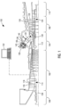
- FIG. 1 illustrates an example of a gas turbine engine 100 including a compressor section 102, a combustion section 104, and a turbine section 106 arranged along a central axis 112.
- the compressor section 102 includes a plurality of compressor stages 114 with each compressor stage 114 including a set of stationary compressor vanes 116 or adjustable guide vanes and a set of rotating compressor blades 118.
- a rotor 134 supports the rotating compressor blades 118 for rotation about the central axis 112 during operation.
- a single one-piece rotor 134 extends the length of the gas turbine engine 100 and is supported for rotation by a bearing at either end.
- the rotor 134 is assembled from several separate spools that are attached to one another or may include multiple disk sections that are attached via a bolt or plurality of bolts.
- the compressor section 102 is in fluid communication with an inlet section 108 to allow the gas turbine engine 100 to draw atmospheric air into the compressor section 102. During operation of the gas turbine engine 100, the compressor section 102 draws in atmospheric air and compresses that air for delivery to the combustion section 104.
- the illustrated compressor section 102 is an example of one compressor section 102 with other arrangements and designs being possible.
- the turbine section 106 includes a plurality of turbine stages 124 with each turbine stage 124 including a number of stationary turbine vanes 126 and a number of rotating turbine blades 128.
- the turbine stages 124 are arranged to receive the exhaust gas 122 from the combustion section 104 at a turbine inlet 130 and expand that gas to convert thermal and pressure energy into rotating or mechanical work.
- the turbine section 106 is connected to the compressor section 102 to drive the compressor section 102.
- the turbine section 106 is also connected to a generator, pump, or other device to be driven.
- the compressor section 102 other designs and arrangements of the turbine section 106 are possible.
- An exhaust portion 110 is positioned downstream of the turbine section 106 and is arranged to receive the expanded flow of exhaust gas 122 from the final turbine stage 124 in the turbine section 106.
- the exhaust portion 110 is arranged to efficiently direct the exhaust gas 122 away from the turbine section 106 to assure efficient operation of the turbine section 106.
- Many variations and design differences are possible in the exhaust portion 110. As such, the illustrated exhaust portion 110 is but one example of those variations.
- a control system 132 is coupled to the gas turbine engine 100 and operates to monitor various operating parameters and to control various operations of the gas turbine engine 100.
- the control system 132 is typically micro-processor based and includes memory devices and data storage devices for collecting, analyzing, and storing data.
- the control system 132 provides output data to various devices including monitors, printers, indicators, and the like that allow users to interface with the control system 132 to provide inputs or adjustments.
- a user may input a power output set point and the control system 132 may adjust the various control inputs to achieve that power output in an efficient manner.
- the control system 132 can control various operating parameters including, but not limited to variable inlet guide vane positions, fuel flow rates and pressures, engine speed, valve positions, generator load, and generator excitation. Of course, other applications may have fewer or more controllable devices.
- the control system 132 also monitors various parameters to assure that the gas turbine engine 100 is operating properly. Some parameters that are monitored may include inlet air temperature, compressor outlet temperature and pressure, combustor outlet temperature, fuel flow rate, generator power output, bearing temperature, and the like. Many of these measurements are displayed for the user and are logged for later review should such a review be necessary.
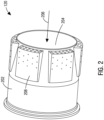
- FIG. 2 illustrates a perspective view of a portion of the combustor 120 of FIG. 1 .
- the combustor 120 includes a wall 202 that surrounds a combustor interior 204.
- a fluid 206 flows through the combustor interior 204.
- the wall 202 may be the combustor liner 138 and the combustor interior 204 is the combustor chamber 140 and the fluid 206 is the exhaust gas 122.
- the wall 202 may the flow sleeve 136 and the combustor interior 204 is the compressed air plenum 142 and the fluid 206 is the compressed air from the compressor section 102.
- the combustor 120 includes a plurality of resonators 208 that are coupled to the wall 202. Each resonator 208 of the plurality of resonators 208 is arranged circumferentially spaced apart from each other around the wall 202. The resonators 208 attenuates frequency dynamics, such as low frequency dynamics, intermediate frequency dynamics, or high frequency dynamics.
- the resonator 208 may be Helmholtz resonators, or any other resonators suitable for the combustor 120.
- FIG. 3 illustrates a perspective exploded view of the portion of the combustor 120 of FIG. 2 showing one resonator 208 of the plurality of resonators 208.
- the wall 202 includes a plurality of slots 302 that extends through the wall 202.
- a total number of slots 302 equals a total number of the resonators 208.
- Each slot 302 of the plurality of slots 302 is rectangular in shape.
- the plurality of slots 302 are arranged circumferentially around the wall 202 and evenly spaced apart from each other.
- the plurality of slots 302 are identical with each other. In other constructions, the plurality of slots 302 may have different configurations.
- the plurality of slots 302 may have a shape other than rectangular, such as diamond, hexagon, octagon, circle, ellipse, etc. Additionally, each slot 302 of the plurality of slots 302 may not have the same shape or size as the other slots 302 and/or may be unevenly distributed around the wall 202.
- the resonator 208 includes a resonator box 304 and a resonator segment 306.
- the resonator box 304 is attached to the wall 202 to enclose a corresponding resonator segment 306.
- a resonator interior 312 is defined between the wall 202 and the resonator box 304.
- the resonator box 304 is attached to the wall 202 by welding, with other joining methods possible.
- the resonator segment 306 includes a plurality of resonator inlets 308 and a plurality of resonator outlets 310. In the construction illustrated in FIG. 3 , the resonator segment 306 has four resonator outlets 310 and four resonator inlets 308. Each resonator segment 306 is identical with the other resonator segments 306. In other constructions, the resonator segment 306 may have more or less than four resonator outlets 310 and four resonator inlets 308. Additionally, each resonator segment 306 may have different configuration from the other resonator segments 306, such as different shape, different size, or different numbers of resonator outlets 310 and resonator inlets 308.
- a resonator neck 602 connects each of the resonator inlet 308 with a corresponding resonator outlet 310.
- the resonator segment 306 When assembled, the resonator segment 306 is attached to the wall 202 to cover the slot 302 such that the plurality of resonator outlets 310 are in flow communication with the combustor interior 204.
- the plurality of resonator inlets 308 are positioned within the resonator interior 312.
- the resonator segment 306 is attached to the wall 202 by welding, with other joining methods possible.
- FIG. 4 is a perspective view of the resonator box 304 of FIG. 3 in an operating position.
- the resonator box 304 includes an outer shell 402, an upstream plate 404 that is positioned on an upstream side of the outer shell 402 with respect to the flow direction of the fluid 206, a downstream plate 406 that is positioned on a downstream side of the outer shell 402 with respect to the flow direction of the fluid 206.
- the upstream plate 404 is a planar plate that also includes an inner curved edge, an outer curved edge, a first straight edge, and a second straight edge.
- the inner curved edge of the upstream plate 404 is arranged to match the contour of the wall 202 and is attached to the wall 202.
- the outer curved edge of the upstream plate 404 is parallel to the inner curved edge of the upstream plate 404 and spaced radially outward.
- the downstream plate 406 is a planar plate that includes an inner curved edge, an outer curved edge, a first straight edge, and a second straight edge.
- the inner curved edge of the downstream plate 406 is arranged to match the contour of the wall 202 and is attached to the wall 202.
- the outer curved edge of the downstream plate 406 is parallel to the inner curved edge of the downstream plate 406 and spaced radially outward.
- the outer shell 402 includes a top surface 408, a first side surface 410, and a second side surface 412 that cooperate to define a U-shape.
- the top surface 408 has a curved shape that is substantially parallel to the wall 202 with a larger radius than the wall 202.
- the first side surface 410 and the second side surface 412 are planar surfaces.
- the first side surface 410 is positioned oblique to the top surface 408.
- the second side surface 412 is positioned oblique to the top surface 408. In other constructions, the first side surface 410 and/or the second side surface 412 may be positioned perpendicular to the top surface 408.
- the downstream plate 406 and the upstream plate 404 are attach to the outer shell 402 and more specifically attach to the top surface 408.
- the upstream plate 404 is positioned oblique to the top surface 408.
- the downstream plate 406 is positioned oblique to the top surface 408. In other constructions, the upstream plate 404 and the downstream plate 406 may be positioned perpendicular to the top surface 408.
- a plurality of first purge holes 414 extend through the upstream plate 404.
- Purge air 418 passes through the plurality of first purge holes 414 into the resonator interior 312.
- a plurality of second purge holes 416 extend through the top surface 408.
- the purge air 418 also passes through the plurality of second purge holes 416 into the resonator interior 312.
- the purge air 418 is the compressed air from the compressor section 102. In other constructions, the purge air 418 may be from a source other than the compressor section 102.
- the plurality of second purge holes 416 are arranged on the top surface 408 closer to the upstream plate 404 than to the downstream plate 406.
- the plurality of first purge holes 414 and the plurality of second purge holes 416 may have the same or different configurations. The configuration may include shape, dimension, etc.
- the resonator box 304 is manufactured by press forming as a single piece.
- the outer shell 402, the upstream plate 404, and the downstream plate 406 may be manufactured as separated pieces, with the upstream plate 404 and the downstream plate 406 welded to the outer shell 402.
- each of the top surface 408, the first side surface 410, the second side surface 412, the upstream plate 404, and the downstream plate 406 may be manufactured as a separated piece and welded together, or the resonator box 304 may be manufactured as a single piece by an additive manufacture process including a layer-by-layer addition of materials, such as would be done using a selective laser melting (SLM) process.
- SLM selective laser melting
- FIG. 5 illustrates a perspective view of the resonator segment 306 of FIG. 3 .
- the resonator segment 306 has an upper surface 502, a lower surface 504, an upstream surface 506 that extends between the upper surface 502 and the lower surface 504 at an upstream side, and a downstream surface 508 that extends between the upper surface 502 and the lower surface 504 at a downstream side.
- the upper surface 502, the lower surface 504, the upstream surface 506, and the downstream surface 508 are curved surfaces.
- the downstream surface 508 is a sloped surface between the upper surface 502 and the lower surface 504.
- the plurality of resonator inlets 308 are defined on the upstream surface 506 and evenly distributed on the upstream surface 506.
- the plurality of resonator outlets 310 are defined on the lower surface 504 (not shown in FIG. 5 ). With reference to FIG. 3 , the plurality of resonator outlets 310 are evenly distributed on the lower surface 504. In other constructions, the plurality of resonator inlets 308 may be unevenly distributed on the upstream surface 506 and/or the plurality of resonator outlet 310 may be unevenly distributed on the lower surface 504.
- the resonator segment 306 is manufactured by an additive manufacture process including a layer-by-layer addition of materials, such as a SLM process. In other constructions, the resonator segment 306 may be manufactured by other manufacturing methods, such as forming, machining, etc.
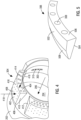
- FIG. 6 illustrates a perspective cutout view of a portion of the combustor 120 of FIG. 2 .
- the resonator segment 306 is attached to the wall 202 and more specifically the lower surface 504 is attached to the wall 202.
- the resonator box 304 is attached to the wall 202 and encloses the resonator segment 306.
- the upper surface 502 is adjacent to the top surface 408 with a gap therebetween.
- the gap may be between 0.5 mm to 2 mm, with other dimensions possible.
- the resonator 208 may be manufactured as a single piece with no gap between the upper surface 502 and the top surface 408.
- the resonator 208 may be manufactured by an additive manufacture process including a layer-by-layer addition of materials, such as a SLM process.
- the resonator segment 306 is fully positioned outside of the wall 202.
- the plurality of resonator inlets 308 are positioned within the resonator interior 312. As is better illustrated in FIG. 4 , the plurality of resonator outlets 310 are positioned on the slot 302.
- the resonator box 304 is positioned such that the plurality of second purge holes 416 are upstream of the plurality of resonator inlets 308.
- the resonator segment 306 has a plurality of resonator necks 602 that are spaced apart from each other. Each resonator neck 602 of the plurality of resonator necks 602 extends from one resonator inlet 308 to a corresponding resonator outlet 310.
- the resonator neck 602 has a hollow interior that defines a flow path between the resonator inlet 308 and the resonator outlet 310 to guide the purge air 418.
- the resonator neck 602 has a curved shape including a first portion 604 and a second portion 606.
- the first portion 604 extends from the resonator outlet 310 to a turning point 608.
- the second portion 606 extends from the turning point 608 to the resonator inlet 308.
- the first portion 604 and the second portion 606 cooperate to define an angle therebetween. The angle is between 15 degrees to 165 degrees.
- the flow path between the resonator outlet 310 and the resonator inlet 308 is a nonlinear flow path that is defined by a curvature of the resonator neck 602.
- the resonator 208 including the resonator box 304 and the resonator segment 306 is made from a material that is different from the wall 202.
- the material of the resonator 208 has a stronger strength than the material of the wall 202.
- the resonator 208 may be made from nickel-chromium-based superalloy and the wall 202 may be made from high alloy steel, such as stainless steel. with other suitable materials possible.
- the resonator 208 including the resonator box 304 and the resonator segment 306 may be made from the same material as the wall 202.
- the purge air 418 enters the resonator interior 312 through the plurality of first purge holes 414 and the plurality of second purge holes 416.
- the purge air 418 enters each resonator neck 602 from the plurality of resonator inlets 308 and is guided through the nonlinear flow path defined by the resonator neck 602 and is discharged into the combustor interior 204 through the plurality of resonator outlets 310.
- Each resonator segment 306 including the nonlinear resonator neck 602 is fully positioned outside of the wall 202 without protruding into the combustor interior 204. As such, each resonator 208 has no impact on the fluid 206 in the combustor interior 204 and thus does not affect the aerodynamics of the combustor 120.
- acoustic vibrations occur in the resonator interior 312 when there are pressure fluctuations in the fluid 206 which causes the fluid 206 oscillates passing through the plurality of resonator outlets 310. These vibrations are excited by fluid dynamic mechanism such as Helmholtz resonance and/or Karman oscillations.
- the purge air 418 dampens the oscillations and the acoustic vibrations.
- the configuration of the resonator 212 such as the number of resonator necks 602, the size of the resonator necks 602, the shape of the resonator necks 602, etc., are selected to tune the frequency of the resonator 212 to a desired frequency range.
- the damping effect of the resonators 208 improves dynamics of the combustor 120 while having no impact on the aerodynamics of the combustor 120.
Landscapes
- Engineering & Computer Science (AREA)
- Chemical & Material Sciences (AREA)
- Combustion & Propulsion (AREA)
- Mechanical Engineering (AREA)
- General Engineering & Computer Science (AREA)
- Structures Of Non-Positive Displacement Pumps (AREA)
- Turbine Rotor Nozzle Sealing (AREA)
Applications Claiming Priority (1)
| Application Number | Priority Date | Filing Date | Title |
|---|---|---|---|
| US202363519283P | 2023-08-14 | 2023-08-14 |
Publications (2)
| Publication Number | Publication Date |
|---|---|
| EP4528162A2 true EP4528162A2 (de) | 2025-03-26 |
| EP4528162A3 EP4528162A3 (de) | 2025-04-02 |
Family
ID=88507425
Family Applications (1)
| Application Number | Title | Priority Date | Filing Date |
|---|---|---|---|
| EP24193566.7A Pending EP4528162A3 (de) | 2023-08-14 | 2024-08-08 | Brennkammer mit resonator für gasturbinenmotor |
Country Status (4)
| Country | Link |
|---|---|
| US (1) | US12607355B2 (de) |
| EP (1) | EP4528162A3 (de) |
| CN (1) | CN119508844A (de) |
| GB (1) | GB2632877A (de) |
Family Cites Families (17)
| Publication number | Priority date | Publication date | Assignee | Title |
|---|---|---|---|---|
| JP3676228B2 (ja) * | 2000-12-06 | 2005-07-27 | 三菱重工業株式会社 | ガスタービン燃焼器およびガスタービン並びにジェットエンジン |
| US7080514B2 (en) * | 2003-08-15 | 2006-07-25 | Siemens Power Generation,Inc. | High frequency dynamics resonator assembly |
| US7334408B2 (en) * | 2004-09-21 | 2008-02-26 | Siemens Aktiengesellschaft | Combustion chamber for a gas turbine with at least two resonator devices |
| US7413053B2 (en) * | 2006-01-25 | 2008-08-19 | Siemens Power Generation, Inc. | Acoustic resonator with impingement cooling tubes |
| US20100206664A1 (en) * | 2007-07-12 | 2010-08-19 | Rolls-Royce Plc | Acoustic panel |
| US8061141B2 (en) * | 2007-09-27 | 2011-11-22 | Siemens Energy, Inc. | Combustor assembly including one or more resonator assemblies and process for forming same |
| US20100236245A1 (en) * | 2009-03-19 | 2010-09-23 | Johnson Clifford E | Gas Turbine Combustion System |
| US9546558B2 (en) * | 2010-07-08 | 2017-01-17 | Siemens Energy, Inc. | Damping resonator with impingement cooling |
| EP2762784B1 (de) * | 2012-11-30 | 2016-02-03 | Alstom Technology Ltd | Dämpfvorrichtung für eine Gasturbinenbrennkammer |
| US9400108B2 (en) | 2013-05-14 | 2016-07-26 | Siemens Aktiengesellschaft | Acoustic damping system for a combustor of a gas turbine engine |
| US9410484B2 (en) * | 2013-07-19 | 2016-08-09 | Siemens Aktiengesellschaft | Cooling chamber for upstream weld of damping resonator on turbine component |
| JP6579834B2 (ja) * | 2015-07-08 | 2019-09-25 | 三菱日立パワーシステムズ株式会社 | 燃焼器及びガスタービン |
| DE102015216772A1 (de) * | 2015-09-02 | 2017-03-02 | Siemens Aktiengesellschaft | Verfahren zur Fertigung und Montage eines Resonators für einen Brenner |
| US10220474B2 (en) * | 2016-12-02 | 2019-03-05 | General Electricd Company | Method and apparatus for gas turbine combustor inner cap and high frequency acoustic dampers |
| US11536174B2 (en) * | 2017-07-20 | 2022-12-27 | President And Fellows Of Harvard College | Acoustic damper for gas turbine combustors with orthogonal slots |
| CN113776088A (zh) * | 2021-09-24 | 2021-12-10 | 中国联合重型燃气轮机技术有限公司 | 火焰筒、燃烧室及燃气轮机 |
| CN117109030B (zh) * | 2022-05-16 | 2025-09-19 | 通用电气公司 | 燃烧器衬里中的热声阻尼器 |
-
2023
- 2023-09-14 GB GB2314052.8A patent/GB2632877A/en active Pending
-
2024
- 2024-08-08 EP EP24193566.7A patent/EP4528162A3/de active Pending
- 2024-08-09 US US18/799,240 patent/US12607355B2/en active Active
- 2024-08-12 CN CN202411097551.4A patent/CN119508844A/zh active Pending
Also Published As
| Publication number | Publication date |
|---|---|
| GB2632877A (en) | 2025-02-26 |
| GB202314052D0 (en) | 2023-11-01 |
| EP4528162A3 (de) | 2025-04-02 |
| US20250060105A1 (en) | 2025-02-20 |
| CN119508844A (zh) | 2025-02-25 |
| US12607355B2 (en) | 2026-04-21 |
Similar Documents
| Publication | Publication Date | Title |
|---|---|---|
| US7955051B2 (en) | Diffuser/guide vane assembly for a turbomachine | |
| US12565998B2 (en) | Combustor for a gas turbine engine including a collar surrounding a secondary fuel injector to define upstream and downstream purge paths | |
| US12158271B2 (en) | Premixer injector in gas turbine engine | |
| EP4311914B1 (de) | Turbinenlaufschaufel | |
| US12601491B2 (en) | Combustor having secondary fuel injector | |
| US12607355B2 (en) | Combustor with resonator for gas turbine engine | |
| US20250198305A1 (en) | Gas turbine engine with turbine vane carrier cooling flow path | |
| US12398644B2 (en) | Manifold for turbine blade of gas turbine engine | |
| US20260063042A1 (en) | Transition duct for gas turbine engine | |
| EP4100628B1 (de) | Strebenabdeckung für eine turbine | |
| EP4592497A1 (de) | Wärmeabdeckung für rotor eines gasturbinenmotors | |
| US12116906B2 (en) | Turbine vane in gas turbine engine | |
| US12018591B2 (en) | Ring segment assembly in gas turbine engine | |
| WO2025031821A1 (en) | Cooled double wall component of a gas turbine engine | |
| WO2022055686A2 (en) | Sacrificial plate in membrane slot for an exit ring | |
| GB2633337A (en) | Turbine component for gas turbine engine |
Legal Events
| Date | Code | Title | Description |
|---|---|---|---|
| PUAI | Public reference made under article 153(3) epc to a published international application that has entered the european phase |
Free format text: ORIGINAL CODE: 0009012 |
|
| STAA | Information on the status of an ep patent application or granted ep patent |
Free format text: STATUS: THE APPLICATION HAS BEEN PUBLISHED |
|
| PUAL | Search report despatched |
Free format text: ORIGINAL CODE: 0009013 |
|
| AK | Designated contracting states |
Kind code of ref document: A2 Designated state(s): AL AT BE BG CH CY CZ DE DK EE ES FI FR GB GR HR HU IE IS IT LI LT LU LV MC ME MK MT NL NO PL PT RO RS SE SI SK SM TR |
|
| AK | Designated contracting states |
Kind code of ref document: A3 Designated state(s): AL AT BE BG CH CY CZ DE DK EE ES FI FR GB GR HR HU IE IS IT LI LT LU LV MC ME MK MT NL NO PL PT RO RS SE SI SK SM TR |
|
| RIC1 | Information provided on ipc code assigned before grant |
Ipc: F23R 3/46 20060101ALI20250226BHEP Ipc: F23R 3/00 20060101AFI20250226BHEP |
|
| STAA | Information on the status of an ep patent application or granted ep patent |
Free format text: STATUS: REQUEST FOR EXAMINATION WAS MADE |
|
| 17P | Request for examination filed |
Effective date: 20250716 |