EP4528127A1 - Transmission - Google Patents
Transmission Download PDFInfo
- Publication number
- EP4528127A1 EP4528127A1 EP23819924.4A EP23819924A EP4528127A1 EP 4528127 A1 EP4528127 A1 EP 4528127A1 EP 23819924 A EP23819924 A EP 23819924A EP 4528127 A1 EP4528127 A1 EP 4528127A1
- Authority
- EP
- European Patent Office
- Prior art keywords
- cam
- transmission
- biasing mechanism
- output shaft
- input shaft
- Prior art date
- Legal status (The legal status is an assumption and is not a legal conclusion. Google has not performed a legal analysis and makes no representation as to the accuracy of the status listed.)
- Pending
Links
Images




Classifications
-
- F—MECHANICAL ENGINEERING; LIGHTING; HEATING; WEAPONS; BLASTING
- F16—ENGINEERING ELEMENTS AND UNITS; GENERAL MEASURES FOR PRODUCING AND MAINTAINING EFFECTIVE FUNCTIONING OF MACHINES OR INSTALLATIONS; THERMAL INSULATION IN GENERAL
- F16H—GEARING
- F16H3/00—Toothed gearings for conveying rotary motion with variable gear ratio or for reversing rotary motion
- F16H3/02—Toothed gearings for conveying rotary motion with variable gear ratio or for reversing rotary motion without gears having orbital motion
- F16H3/08—Toothed gearings for conveying rotary motion with variable gear ratio or for reversing rotary motion without gears having orbital motion exclusively or essentially with continuously meshing gears, that can be disengaged from their shafts
- F16H3/087—Toothed gearings for conveying rotary motion with variable gear ratio or for reversing rotary motion without gears having orbital motion exclusively or essentially with continuously meshing gears, that can be disengaged from their shafts characterised by the disposition of the gears
- F16H3/089—Toothed gearings for conveying rotary motion with variable gear ratio or for reversing rotary motion without gears having orbital motion exclusively or essentially with continuously meshing gears, that can be disengaged from their shafts characterised by the disposition of the gears all of the meshing gears being supported by a pair of parallel shafts, one being the input shaft and the other the output shaft, there being no countershaft involved
-
- F—MECHANICAL ENGINEERING; LIGHTING; HEATING; WEAPONS; BLASTING
- F16—ENGINEERING ELEMENTS AND UNITS; GENERAL MEASURES FOR PRODUCING AND MAINTAINING EFFECTIVE FUNCTIONING OF MACHINES OR INSTALLATIONS; THERMAL INSULATION IN GENERAL
- F16D—COUPLINGS FOR TRANSMITTING ROTATION; CLUTCHES; BRAKES
- F16D23/00—Details of mechanically-actuated clutches not specific for one distinct type
- F16D23/02—Arrangements for synchronisation, also for power-operated clutches
- F16D23/04—Arrangements for synchronisation, also for power-operated clutches with an additional friction clutch
- F16D23/06—Arrangements for synchronisation, also for power-operated clutches with an additional friction clutch and a blocking mechanism preventing the engagement of the main clutch prior to synchronisation
-
- F—MECHANICAL ENGINEERING; LIGHTING; HEATING; WEAPONS; BLASTING
- F16—ENGINEERING ELEMENTS AND UNITS; GENERAL MEASURES FOR PRODUCING AND MAINTAINING EFFECTIVE FUNCTIONING OF MACHINES OR INSTALLATIONS; THERMAL INSULATION IN GENERAL
- F16H—GEARING
- F16H57/00—General details of gearing
- F16H57/04—Features relating to lubrication or cooling or heating
- F16H57/042—Guidance of lubricant
- F16H57/043—Guidance of lubricant within rotary parts, e.g. axial channels or radial openings in shafts
-
- F—MECHANICAL ENGINEERING; LIGHTING; HEATING; WEAPONS; BLASTING
- F16—ENGINEERING ELEMENTS AND UNITS; GENERAL MEASURES FOR PRODUCING AND MAINTAINING EFFECTIVE FUNCTIONING OF MACHINES OR INSTALLATIONS; THERMAL INSULATION IN GENERAL
- F16H—GEARING
- F16H57/00—General details of gearing
- F16H57/04—Features relating to lubrication or cooling or heating
- F16H57/048—Type of gearings to be lubricated, cooled or heated
- F16H57/0493—Gearings with spur or bevel gears
- F16H57/0494—Gearings with spur or bevel gears with variable gear ratio or for reversing rotary motion
-
- F—MECHANICAL ENGINEERING; LIGHTING; HEATING; WEAPONS; BLASTING
- F16—ENGINEERING ELEMENTS AND UNITS; GENERAL MEASURES FOR PRODUCING AND MAINTAINING EFFECTIVE FUNCTIONING OF MACHINES OR INSTALLATIONS; THERMAL INSULATION IN GENERAL
- F16D—COUPLINGS FOR TRANSMITTING ROTATION; CLUTCHES; BRAKES
- F16D23/00—Details of mechanically-actuated clutches not specific for one distinct type
- F16D23/02—Arrangements for synchronisation, also for power-operated clutches
- F16D23/04—Arrangements for synchronisation, also for power-operated clutches with an additional friction clutch
- F16D23/06—Arrangements for synchronisation, also for power-operated clutches with an additional friction clutch and a blocking mechanism preventing the engagement of the main clutch prior to synchronisation
- F16D2023/0618—Details of blocking mechanism comprising a helical spring loaded element, e.g. ball
-
- F—MECHANICAL ENGINEERING; LIGHTING; HEATING; WEAPONS; BLASTING
- F16—ENGINEERING ELEMENTS AND UNITS; GENERAL MEASURES FOR PRODUCING AND MAINTAINING EFFECTIVE FUNCTIONING OF MACHINES OR INSTALLATIONS; THERMAL INSULATION IN GENERAL
- F16D—COUPLINGS FOR TRANSMITTING ROTATION; CLUTCHES; BRAKES
- F16D23/00—Details of mechanically-actuated clutches not specific for one distinct type
- F16D23/02—Arrangements for synchronisation, also for power-operated clutches
- F16D23/04—Arrangements for synchronisation, also for power-operated clutches with an additional friction clutch
- F16D23/06—Arrangements for synchronisation, also for power-operated clutches with an additional friction clutch and a blocking mechanism preventing the engagement of the main clutch prior to synchronisation
- F16D2023/0637—Details relating to the hub member on which the sliding is arranged
-
- F—MECHANICAL ENGINEERING; LIGHTING; HEATING; WEAPONS; BLASTING
- F16—ENGINEERING ELEMENTS AND UNITS; GENERAL MEASURES FOR PRODUCING AND MAINTAINING EFFECTIVE FUNCTIONING OF MACHINES OR INSTALLATIONS; THERMAL INSULATION IN GENERAL
- F16H—GEARING
- F16H3/00—Toothed gearings for conveying rotary motion with variable gear ratio or for reversing rotary motion
- F16H3/02—Toothed gearings for conveying rotary motion with variable gear ratio or for reversing rotary motion without gears having orbital motion
- F16H3/08—Toothed gearings for conveying rotary motion with variable gear ratio or for reversing rotary motion without gears having orbital motion exclusively or essentially with continuously meshing gears, that can be disengaged from their shafts
- F16H2003/0811—Toothed gearings for conveying rotary motion with variable gear ratio or for reversing rotary motion without gears having orbital motion exclusively or essentially with continuously meshing gears, that can be disengaged from their shafts using unsynchronised clutches
-
- F—MECHANICAL ENGINEERING; LIGHTING; HEATING; WEAPONS; BLASTING
- F16—ENGINEERING ELEMENTS AND UNITS; GENERAL MEASURES FOR PRODUCING AND MAINTAINING EFFECTIVE FUNCTIONING OF MACHINES OR INSTALLATIONS; THERMAL INSULATION IN GENERAL
- F16H—GEARING
- F16H3/00—Toothed gearings for conveying rotary motion with variable gear ratio or for reversing rotary motion
- F16H3/02—Toothed gearings for conveying rotary motion with variable gear ratio or for reversing rotary motion without gears having orbital motion
- F16H3/08—Toothed gearings for conveying rotary motion with variable gear ratio or for reversing rotary motion without gears having orbital motion exclusively or essentially with continuously meshing gears, that can be disengaged from their shafts
- F16H2003/0818—Toothed gearings for conveying rotary motion with variable gear ratio or for reversing rotary motion without gears having orbital motion exclusively or essentially with continuously meshing gears, that can be disengaged from their shafts comprising means for power-shifting
-
- F—MECHANICAL ENGINEERING; LIGHTING; HEATING; WEAPONS; BLASTING
- F16—ENGINEERING ELEMENTS AND UNITS; GENERAL MEASURES FOR PRODUCING AND MAINTAINING EFFECTIVE FUNCTIONING OF MACHINES OR INSTALLATIONS; THERMAL INSULATION IN GENERAL
- F16H—GEARING
- F16H63/00—Control outputs from the control unit to change-speed- or reversing-gearings for conveying rotary motion or to other devices than the final output mechanism
- F16H63/02—Final output mechanisms therefor; Actuating means for the final output mechanisms
- F16H63/30—Constructional features of the final output mechanisms
- F16H2063/3089—Spring assisted shift, e.g. springs for accumulating energy of shift movement and release it when clutch teeth are aligned
-
- F—MECHANICAL ENGINEERING; LIGHTING; HEATING; WEAPONS; BLASTING
- F16—ENGINEERING ELEMENTS AND UNITS; GENERAL MEASURES FOR PRODUCING AND MAINTAINING EFFECTIVE FUNCTIONING OF MACHINES OR INSTALLATIONS; THERMAL INSULATION IN GENERAL
- F16H—GEARING
- F16H63/00—Control outputs from the control unit to change-speed- or reversing-gearings for conveying rotary motion or to other devices than the final output mechanism
- F16H63/02—Final output mechanisms therefor; Actuating means for the final output mechanisms
- F16H63/30—Constructional features of the final output mechanisms
- F16H2063/3093—Final output elements, i.e. the final elements to establish gear ratio, e.g. coupling sleeves or other means establishing coupling to shaft
-
- F—MECHANICAL ENGINEERING; LIGHTING; HEATING; WEAPONS; BLASTING
- F16—ENGINEERING ELEMENTS AND UNITS; GENERAL MEASURES FOR PRODUCING AND MAINTAINING EFFECTIVE FUNCTIONING OF MACHINES OR INSTALLATIONS; THERMAL INSULATION IN GENERAL
- F16H—GEARING
- F16H2200/00—Transmissions for multiple ratios
- F16H2200/003—Transmissions for multiple ratios characterised by the number of forward speeds
- F16H2200/0052—Transmissions for multiple ratios characterised by the number of forward speeds the gear ratios comprising six forward speeds
Definitions
- the present teaching relates to a transmission capable of performing seamless shift up.
- a transmission capable of performing seamless shift up has been known.
- the transmission includes an input shaft connected to a driving source and an output shaft connected to a driving target.
- shift gears are provided to be rotatable relative to one another.
- the shift gears are provided to correspond to speed stages in number, and are arranged so that transmission ratios are different between the speed stages.
- the transmission allows selection of a shift gear that is rotated together with the input shaft or the output shaft. Through the selected shift gear, power is transmitted from the input shaft to the output shaft.
- Patent Literature 1 discloses a transmission which is capable of performing seamless shift up.
- the transmission of Patent Literature 1 is arranged so that, when shifting up, two sliders are temporarily connected to the shift gear at the same time.
- a force in an axial direction is generated to cancel the connection of one of the two sliders.
- seamless shift up is achieved without interrupting the transmission of power.
- the transmission of Patent Literature 1 is provided with a cam biasing mechanism that is provided on each of an input shaft and an output shaft so as to make contact with a cam surface on the slider.
- the cam biasing mechanism is pressed onto the cam surface of the slider, the slider receives a force acting toward the shift gear.
- the slider can be moved by the cam biasing mechanism from a drive meshed position to a coast meshed position.
- Patent Literature 1 International Publication No. 2020/250535
- a cam biasing mechanism of Patent Literature 1 is formed of a ball and a coil spring. A part of the ball and a majority of the coil spring are accommodated in a clutch hub that is provided at the outer circumferences of the input shaft and the output shaft, in order to exert an elastic force of the coil spring to the ball. End portions of the coil spring are fitted into recesses formed in outer circumferential surfaces of the input shaft and the output shaft, respectively.
- the ball protrudes from the clutch hub and is in contact with a cam surface formed on a slider. As the ball makes contact with the cam surface, a radial force exerted to the cam surface is converted to a force acting in the axial direction of the input shaft and the output shaft. To put it differently, the ball of the cam biasing mechanism makes contact with the cam surface and presses the slider in the axial direction, with the result that the slider is moved.
- the number of springs of the cam biasing mechanism may be increased or each spring of the cam biasing mechanism may be elongated.
- the number of springs is increased, the strength and rigidity of the input shaft and the output shaft are deteriorated because the number of the recesses formed in the outer circumferential surfaces of the input shaft and the output shaft is increased.
- the transmission is disadvantageously upsized because the cam biasing mechanism is upsized.
- An object of the present teaching is to increase the elastic force of a spring of a cam biasing mechanism when the spring is in contact with a cam surface and presses a slider in an axial direction and to downsize a transmission capable of performing seamless shift up, while maintaining both the strength and rigidity of an input shaft and an output shaft.
- the transmission comprises: an input shaft connected to a driving source and an output shaft connected to a driving target, on the input shaft and the output shaft, shift gears being provided to be each rotatable relative to the input shaft or the output shaft and immovable in an axial direction of the input shaft and the output shaft, the shift gears corresponding to speed stages in number, on the input shaft and the output shaft, sliders being provided to be each rotatable together with the input shaft or the output shaft, movable in the axial direction of the input shaft and the output shaft by a shift fork, and connectable to at least one of the shift gears, two of the sliders being temporarily in a state of being connected simultaneously with two of the shift gears when shifting up, and when the state of being simultaneously connected is established, a force of canceling connection of one of the two sliders being generated, at least one cam biasing mechanism being provided on at least one of the input shaft or the output shaft to impart an elastic force to at least one of the sliders in a radial direction of the input shaft or the output shaft,
- the spring constituting the cam biasing mechanism is provided in the communication hole formed in the input shaft or the output shaft.
- the spring is at least partially accommodated in the input shaft or the output shaft. Because the communication hole is formed inside the input shaft or the output shaft, the length in the radial direction of the hole accommodating the spring can be easily elongated as compared to a case where a hole accommodating a spring is formed in a component provided on the outer circumference of the input shaft or the output shaft. It is therefore easy to ensure the spring to be sufficiently long and have a sufficient elastic force.
- the spring is at least partially provided in the communication hole connected to the lubricating oil passage at an end on the opposite side of the opening portion, the spring can be elongated as compared to a case where the spring is at least partially provided in a recess that has an opening portion in the outer circumferential surface of at least one of the input shaft or the output shaft and does not communicate with the lubricating oil passage.
- This arrangement makes it possible to secure the elastic force of the spring even if the communication hole is short in diameter.
- the spring is partially provided in the lubricating oil passage so that the spring intersects with the lubricating oil passage, a part of the spring which is inside the lubricating oil passage tends to be deformed in a direction different from the elongation-contraction direction, e.g., in the axial direction.
- the support member is at least partially provided in the lubricating oil passage so that the support member intersects with the lubricating oil passage.
- the communication hole in which at least part of the spring is provided is formed so that the length of the first arc at the outer circumferential surface of the input shaft or the output shaft is longer than the second arc.
- This arrangement makes it possible to secure both the strength and rigidity of the input shaft and the output shaft in which the spring is at least partially accommodated in the communication hole.
- the communication hole is formed inside at least one of the input shaft or the output shaft, the transmission is downsized in the axial direction and the radial direction, because, as compared to a case where a communication hole is formed in a component provided on the outer circumference of at least one of the input shaft or the output shaft, such a component is not required. It is therefore possible to downsize the transmission.
- Each of the sliders is configured to be moved in the axial direction by the shift fork from a standby position where the slider is unconnected to the shift gear, and each of the cam surfaces converts the elastic force exerted in the radial direction by the cam biasing mechanism to a force which is exerted in the axial direction to move a slider having the cam surface in a direction opposite to a direction toward the standby position from a position to which the slider is moved by the shift fork.
- the slider can be moved away from the standby position from a position to which the slider has been moved by the shift fork, by an elastic force of the cam biasing mechanism.
- the cam biasing mechanism accommodation unit is formed of two communication holes formed along a single linear line intersecting with a central axial line of the input shaft or the output shaft, and the at least one of the sliders has two cam surfaces which simultaneously receive the elastic force from the cam biasing mechanism.
- the support member along one linear line across the two communication holes and the lubricating oil passage. Furthermore, in the arrangement described above, as the cam biasing mechanism, which includes two springs corresponding to the respective two communication holes and the support member, is inserted from one side of the two communication holes, it is possible to provide the cam biasing mechanism in a space that is along one linear line extending across the two communication holes and the lubricating oil passage. This makes it easy to attach the cam biasing mechanism to at least one of the input shaft or the output shaft. Furthermore, the cam biasing mechanism is structurally simple, and the support member can be shortened. When the support member is shortened, it is easy to arrange the spring to be sufficiently long and have a sufficient elastic force.
- one cam biasing mechanism accommodation unit is formed of two communication holes, the strength and rigidity of at least one of the input shaft or the output shaft can be improved as compared to a case where one cam biasing mechanism accommodation unit is formed of three or more communication holes.
- the cam biasing mechanism includes contact members each of which accommodates at least part of each of the springs, each of which is at least partially provided in the communication hole, and each of which makes contact with a cam surface.
- the spring can be further elongated as the spring is at least partially accommodated in the contact member, as compared to a case where the cam biasing mechanism includes a contact member not accommodating the spring at all, such as a ball recited in Patent Literature 1. Due to this, in the transmission of the present teaching, it is possible to further increase the elastic force of the spring of the cam biasing mechanism when making contact with the cam surface and pressing the slider.
- the spring When the spring is accommodated in the contact member, the spring is not exposed to the lubricating oil passage even if the spring accommodated in the contact member is at least partially provided in the lubricating oil passage. On this account, the deformation of the spring in a direction different from the elongation-contraction direction is further reliably suppressed and hence the spring can smoothly elongate and contract, with the result that the elastic force of the spring is ensured.
- Each of the communication holes is circular in shape in a cross section orthogonal to a central axial line passing through the center of each of the communication holes, each of the contact members has a protruding surface section making contact with the cam surface and a cylindrical section integrated with the protruding surface section, and the protruding surface section is formed as a part of a spherical surface.
- the curvature radius of the ball When a ball making contact with the cam surface is provided as in Patent Literature 1 in place of the contact member having the protruding surface section and the cylindrical section, the curvature radius of the ball must be set in accordance with the angle of the cam surface and the moving distance of the slider, in order to secure the moving distance of the contact member in the radial direction of the input shaft or the output shaft at the time of movement of the slider.
- the curvature radius of the ball is set in accordance with the moving distance of the slider, when the checking groove with which the contact member is fitted is formed in the slider, the load applied from the ball to the checking groove as resistance against the movement of the slider in the axial direction may be not easily adjusted.
- the contact member has the protruding surface section and the cylindrical section
- the cylindrical section is supported by a wall surface of the communication hole and movable in the radial direction of the input shaft or the output shaft, it is unnecessary to change the curvature radius of the protruding surface section in order to secure the moving distance of the contact member in the radial direction of the input shaft or the output shaft due to the movement of the slider, and hence the shape of the protruding surface section can be set at will.
- the degree of freedom in designing the shape of the protruding surface section of the contact member and the shape of the checking groove corresponding to the protruding surface section of the contact member is high, and hence the resistance against the movement in the axial direction of the slider in the state in which the contact member is fitted with the checking groove is easily controllable.
- the curvature radius of the protruding surface section of each of the contact members is longer than the radius of each of the communication holes.
- the contact member has the protruding surface section and the cylindrical section
- the curvature radius of the protruding surface section is increased to adjust the load applied from the contact member to the checking groove as resistance against the movement of the slider in the axial direction
- the curvature radius of the part of the contact member which is in contact with the cam surface is arranged to be longer than the radius of the communication hole in the transmission, both of the strength and rigidity of the input shaft and the output shaft can be secured by avoiding the radius of the communication hole from becoming long.
- Each of the communication holes is circular in shape in a cross section orthogonal to a central axial line passing through the center of each of the communication holes, each of the contact members accommodates each of the springs and an end portion of the support member, and the end portion of the support member, which is accommodated in each of the contact members, has a large diameter portion that is longer in diameter than an open end of each of the contact members.
- the contact member and the support member are connected by a simple structure, the space in which the spring is accommodated can be easily secured in the contact member. It is therefore easy to ensure the spring to be sufficiently long and have a high elastic force.
- the support member has an oil hole through which lubricating oil flows from the lubricating oil passage toward each of the springs, and the cam biasing mechanism is arranged to cause a hydraulic pressure of the lubricating oil flowing out from the oil hole of the support member to act on each of the cam surfaces.
- the lubricating oil in the lubricating oil passage flows into the oil hole, and the lubricating oil having flown into the oil hole flows toward the spring through the oil hole.
- the load on the cam surface from the cam biasing mechanism is not only the elastic force of the spring but also the hydraulic pressure of the lubricating oil, with the result that the load with which the cam biasing mechanism presses the slider in the axial direction is further increased.
- the elastic force of the spring is allowed to be small as compared to a case where no oil hole is provided, the strength and rigidity of the input shaft or the output shaft can be improved by decreasing the diameter of the communication hole or decreasing the number of the communication holes as compared to the case where no oil hole is provided.
- a spline having recesses and protrusions which are alternately provided in the circumferential direction is formed, the at least one of the sliders is fitted with the spline to be movable in the axial direction, when the center of each of the communication holes passes through one of the recesses, a cutout is formed in the spline so that two protrusions neighboring the recess passing through the center of the communication hole form a counterbored shape or two protrusions neighboring the recess passing through the center of the communication hole form a countersunk shape in the axial direction, and when the center of each of the communication holes passes through one of the protrusions, a cutout is formed in the spline so that the protrusion passing through the center of each of the communication holes forms a countersunk shape.
- the spline having the recesses and the protrusions is formed in the outer circumferential surface of at least one of the input shaft or the output shaft.
- the spline has cutouts with which the two protrusions neighboring the recess passing through the center of the communication hole form a counterbored shape.
- the spline has cutouts with which the two protrusions neighboring the recess passing through the center of the communication hole form a countersunk shape in the axial direction.
- the diameter of the communication hole is longer than the width of the recess.
- the countersunk cutouts are formed in the axial direction in the two protrusions neighboring the recess passing through the communication hole, it is possible to avoid the concentration of stress at a part of the protrusion which is close to the opening edge of the communication hole. This makes it possible to increase the strength of at least one of the input shaft or the output shaft.
- the spline has cutouts with which the protrusion passing through the center of the communication hole forms a countersunk shape in the axial direction.
- the countersunk cutouts are formed in the axial direction in the protrusion passing through the communication hole, it is possible to avoid the concentration of stress at an opening edge of an accommodating hole provided at the protrusion.
- the sliders are slide gears each of which has a gear tooth surface engaged with one of the shift gears.
- a transmission is provided on at least part of a power transmission path.
- the power transmission path is a path through which power is transmitted from a driving source to a driving target.
- the transmission is configured to change a transmission ratio.
- the transmission ratio is a ratio of rotation speed of an input shaft of the transmission to rotation speed of an output shaft of the transmission.
- the transmission may include a transmission device configured to change a transmission ratio and a speed reducer configured to reduce the rotation speed of power output from the transmission device, by means of gears, etc. The reduction ratio of the speed reducer is unchanged.
- the transmission is a multistage transmission which has plural shift gears that are immovable in the axial direction of each of the input shaft and the output shaft and correspond to speed stages in number, and which is configured to transmit power from the input shaft to the output shaft through a shift gear corresponded to a selected speed stage.
- the transmission of the present teaching and the description does not include a continuously variable transmission device having no shift gear.
- the transmission of the present teaching and the embodiments may include an auxiliary transmission.
- the transmission is a multistage transmission. In the present teaching and the embodiments, the transmission is a non-synchronous transmission. In the present teaching and the embodiments, the transmission is a constant-mesh transmission. In the present teaching and the embodiments, the transmission may be an AMT (Automated Manual installation) or an MT (Manual Transmission). The AMT is also known as a semi-automatic transmission.
- the transmission is mounted on a vehicle, for example.
- the vehicle on which the transmission is mounted may be a straddled vehicle or an automobile.
- the straddled vehicle includes a motorcycle, a motor tricycle, a four-wheeled buggy (ATV: All Terrain Vehicle), a snowmobile, and a personal watercraft, for example.
- the motorcycle includes a scooter, an engine-equipped bicycle, a moped, etc.
- the transmission may be mounted on an apparatus such as an agricultural machine, which is not a vehicle.
- the driving source is a power source for driving a driving target.
- the driving target is a vehicle, for example, and is at least one driving wheel among at least one front wheel or at least one rear wheel.
- the driving source may include an engine.
- the driving source may include an engine and an electric motor.
- the driving source may include an engine and an electric motor with a power generation function of generating power by the output of the engine (or a generator and an electric motor). In this case, the output of the engine may be used solely for the power generation.
- the axial direction of each of the input shaft and the output shaft is a direction in parallel to each of the rotational central axis of the input shaft and the rotational central axis of the output shaft.
- a cam biasing mechanism may be any mechanism as long as it applies an elastic force to a cam surface of a slider in the radial direction of an input shaft and an output shaft.
- the spring may be a coil spring or a disc spring.
- a support member which is at least partially provided in the lubricating oil passage to intersect with the lubricating oil passage is a support member which is provided so that parts of the lubricating oil passage exist on the respective sides of the support member in the axial direction of the input shaft or the output shaft.
- a slider having cam surfaces when each of the at least one slider has two cam surfaces simultaneously receiving an elastic force from the cam biasing mechanism, a slider having cam surfaces has two cam surfaces which simultaneously receive an elastic force from the cam biasing mechanism.
- the expression "a slider having cam surfaces has two cam surfaces which simultaneously receive an elastic force from the cam biasing mechanism” encompasses a case where a slider having cam surfaces has two cam surfaces which simultaneously receive an elastic force from the cam biasing mechanism and does not have any other cam surface and a case where, in addition to two cam surfaces which simultaneously receive an elastic force from the cam biasing mechanism, a slider having cam surfaces has another cam surface which does not receive an elastic force from the cam biasing mechanism when the two cam surfaces are receiving an elastic force from the cam biasing mechanism.
- At least one of plural options encompasses all conceivable combinations of the options. At least one of plural options may be one of the options, some of the options, or all of the options. For example, at least one of A, B, or C indicates only A, only B, only C, A and B, A and C, B and C, or A, B, and C.
- the number of a constituent feature when the number of a constituent feature is not clearly specified and the constituent feature is expressed in a singular form in English, the number of the constituent feature may be more than one in the present teaching. In the present teaching, the number of the constituent features may be only one.
- connection is not only direct attachment, connection, coupling, and support but also indirect attachment, connection, coupling, and support are included.
- connected and coupled are not limited to physical or mechanical connections and couplings. They also include direct or indirect electrical connections and couplings.
- the term “preferable” is non-exclusive.
- the term “preferable” means “preferable but not limited to”. In this specification, an arrangement which is “preferable” exerts at least the above-described effects of the arrangement of claim 1.
- the term “may” is non-exclusive. The term “may” indicates “may but not must”. In this specification, an arrangement which is explained by using the term “may” exerts at least the above-described effects of the arrangement of claim 1.
- the present teaching is not limited to the configurations and layout of elements described below and/or shown in drawings.
- the present teaching is also applicable to embodiments other than the embodiments described later.
- the present teaching may be implemented as an embodiment other than the below-described embodiment.
- the present teaching may be implemented by suitably combining below-described embodiments and modifications.
- a transmission of the present teaching is able to increase the elastic force of a spring of a cam biasing mechanism when the spring is in contact with a cam surface and presses a slider in an axial direction and to downsize the transmission, while maintaining both the strength and rigidity of an input shaft and an output shaft.
- FIG. 1 shows an example of the transmission 1 of the First Embodiment.
- the transmission 1 includes an input shaft 11 and an output shaft 12.
- the transmission 1 is configured to be able to transmit power of the input shaft 11 to the output shaft 12.
- the input shaft 11 is connected to a driving source 5.
- shift gears 31, 32, 33, 34, 35, and 36 are provided to correspond to speed stages in number.
- shift gears 31, 32, 33, 34, 35, and 36 are provided to correspond to speed stages in number.
- the highest speed stage is the sixth speed stage.
- Each of the shift gears 31, 32, 33, 34, 35, and 36 is provided to be rotatable relative to the input shaft 11 or the output shaft 12 and immovable in the axial direction of the input shaft 11 or the output shaft 12.
- the shift gears 31, 32, 33, 34, 35, and 36 are a first speed gear, a second speed gear, a third speed gear, a fourth speed gear, a fifth speed gear, and a sixth speed gear, respectively.
- an arrow W indicates the axial direction of each of the input shaft 11 and the output shaft 12.
- an axial direction indicates the axial direction of each of the input shaft 11 and the output shaft 12.
- sliders 41, 42, and 43 are provided on the input shaft 11 and the output shaft 12.
- Each of the sliders 41, 42, and 43 is provided to be rotatable together with the input shaft 11 or the output shaft 12 and movable in the axial direction.
- Each of the sliders 41, 42, and 43 is connectable to at least one of the shift gears 31 to 36.
- the slide gears 41, 42, and 43 are connected to the shift forks 131, 132, and 133, respectively.
- the sliders 41, 42, and 43 are moved by the shift forks 131, 132, and 133, respectively.
- Two of the sliders 41, 42, and 43 are arranged to be temporarily in a state of being simultaneously connected to two shift gears among the shift gears 31 to 36, when shift up is performed. To these two sliders, a force of canceling the connection of one of the two sliders is exerted when the sliders are simultaneously connected to two shift gears among the shift gears 31 to 36.
- the transmission 1 is able to perform seamless shift up without interrupting the power.
- the transmission 1 is arranged to be able to seamlessly perform shift up to the second speed stage, the third speed stage, and the fourth speed stage.
- At least one of the input shaft 11 or the output shaft 12 includes a lubricating oil passage 119 and at least one cam biasing mechanism accommodation unit.
- the cam biasing mechanism accommodation unit is formed of plural communication holes 120.
- the communication holes 120 forming one cam biasing mechanism accommodation unit are formed in one cross section that is orthogonal to the axial direction.
- the lubricating oil passages 119 are formed in both the input shaft 11 and the output shaft 12, and two cam biasing mechanism accommodation units are formed in the output shaft 12.
- one cam biasing mechanism accommodation unit has two communication holes 120.
- a power transmission shaft 10 At least one of these shafts that has both the lubricating oil passage 119 and the cam biasing mechanism accommodation unit will be collectively termed a power transmission shaft 10.
- the lubricating oil passage 119 is formed in the power transmission shaft 10 along the axial direction. Lubricating oil flows in the lubricating oil passage 119.
- Each of the communication holes 120 has an opening portion 120c formed in the outer circumferential surface of the power transmission shaft 10.
- Each of the communication holes 120 is connected to the lubricating oil passage 119 at an end that is opposite to the opening portion 120c. While in the example of FIG. 1 the communication holes 120 are identical in size and shape, the disclosure is not limited to this arrangement.
- the communication holes 120 may include two communication holes that are different in size.
- the communication holes 120 may include two communication holes that are different in shape.
- Each of the communication holes 120 is arranged so that, in a cross section orthogonal to the axial direction, the length L1 of a first arc is longer than the length L2 of a second arc.
- the first arc and the second arc are defined as below, with the assumption that, in a cross section orthogonal to the axial direction, ends of the opening portion 120c of the communication hole 120 formed in the outer circumferential surface of the power transmission shaft 10 are opening edges 120a and 120b.
- the first arc is an arc between the opening edge 120a and the opening edge 120b neighboring each other in the circumferential direction of the outer circumferential surface, and does not include any opening portions 120c of the communication holes 120.
- the second arc is an arc between the opening edges 120a and 120b at the respective ends of one communication hole 120.
- the communication holes 120 are provided at regular intervals in the circumferential direction in a cross section orthogonal to the axial direction.
- the disclosure is not limited to this arrangement.
- the communication holes 120 may be provided at irregular intervals in the circumferential direction. In this case, the minimum length of the first arc is arranged to be longer than the maximum length of the second arc.
- the transmission 1 includes at least one cam biasing mechanism 80. Parts of the cam biasing mechanism 80 are accommodated in the communication holes 120. The remaining part of the cam biasing mechanism 80 is accommodated in the lubricating oil passage 119.
- the cam biasing mechanism accommodation unit is provided for each cam biasing mechanism 80. On this account, at least one cam biasing mechanism 80 is provided on at least one of the input shaft 11 or the output shaft 12.
- the cam biasing mechanism 80 is arranged to impart an elastic force in the radial direction of the power transmission shaft 10 to one of the sliders 41, 42, and 43. In the example shown in FIG. 1 , two cam biasing mechanisms 80 are provided for the sliders 41 and 42 on the output shaft 12.
- the cam biasing mechanism 80 includes springs 81 and one support member 83. At least part of each spring 81 is provided in the communication hole 120. The spring 81 is provided for each communication hole 120. To put it differently, the number of springs 81 included in one cam biasing mechanism 80 is identical with the number of communication holes 120 constituting the cam biasing mechanism accommodation unit provided for that cam biasing mechanism 80. Each spring 81 is arranged to be able to elongate and contract in the radial direction of the power transmission shaft 10.
- the support member 83 is at least partially in the lubricating oil passage 119 so that the support member 83 is in contact with the springs 81 and intersects with the lubricating oil passage 119. In the example in FIG. 1 , the support member 83 has a portion in the lubricating oil passage 119 and portions in the communication holes 120. Alternatively, the support member 83 may be entirely in the lubricating oil passage 119.
- At least one of the sliders 41, 42, and 43 has a cam surface 71.
- the at least one slider having the cam surface 71 among the sliders 41, 42, and 43 will be collectively termed a slider 40.
- each of two sliders 41 and 42 has the cam surface 71.
- the number of sliders 40 having the cam surface 71 may be one, or may be more than one.
- the cam surface 71 is formed on one of the two sliders simultaneously connected to two shift gears when shifting up, to which a force of canceling the connection is applied.
- the cam surface 71 makes contact with the cam biasing mechanism 80 so as to convert an elastic force exerted in the radial direction from the cam biasing mechanism 80 to a force exerted in the axial direction.
- the cam biasing mechanism 80 is provided for each slider 40 having the cam surface 71.
- Each slider 40 has plural cam surfaces 71.
- each of the two sliders 41 and 42 has four cam surfaces 71.
- the springs 81 included in the cam biasing mechanism 80 impart elastic forces to the cam surfaces 71 of the slider 40.
- the number of springs 81 in the cam biasing mechanism 80 may be half as many as the number of cam surfaces 71 in the slider 40. In this case, half of the cam surfaces 71 of the slider 40 simultaneously make contact with the cam biasing mechanism 80.
- the number of springs 81 in the cam biasing mechanism 80 may be identical with the number of cam surfaces 71 in the slider 40. In this case, the cam surfaces 71 of the slider 40 simultaneously make contact with the cam biasing mechanism 80.
- the power transmission shaft 10 (the input shaft 11 or the output shaft 12) has two communication holes 120 for one cam biasing mechanism 80.
- the two communication holes 120 are deviated from each other by about 180 degrees in the circumferential direction of the power transmission shaft 10.
- the cam biasing mechanism accommodation unit is composed of two communication holes 120 formed along a single linear line intersecting with the central axial line of the power transmission shaft 10. In this way, the two communication holes 120 and part of the lubricating oil passage 119 form a space extending along one linear line that is in parallel to the radial direction of the power transmission shaft 10. It is noted that the number of the communication holes 120 in the cam biasing mechanism accommodation unit of the First Embodiment may be three or more.
- the sliders 41, 42, and 43 are slide gears 41, 42, and 43.
- Each of the slide gears 41, 42, and 43 has a gear tooth surface which is meshed with a shift gear that is provided on the input shaft 11 or the output shaft 12 which is different from the shaft on which that slide gear is provided.
- One gear tooth surface 45 is meshed with one shift gear.
- Each of the slide gears 41, 42, and 43 has at least one gear tooth surface 45 meshed with at least one shift gear.
- Each gear tooth surface is always meshed with one of the shift gears 31 to 36.
- the slide gear 41 has one gear tooth surface meshed with the shift gear 35
- the slide gear 42 has one gear tooth surface meshed with the shift gear 36
- the slide gear 43 has two gear tooth surfaces meshed with the two shift gears 33 and 34, respectively.
- a meshing gear 21, a fifth speed gear 35, a slide gear 43, a sixth speed gear 36, and a meshing gear 22 are provided in this order in the axial direction.
- the meshing gear 21 is closest to an end portion of the input shaft 11, with which the driving source 5 is connected.
- a first speed gear 31, a slide gear 41, a third speed gear 33, a fourth speed gear 34, a slide gear 42, and a second speed gear 32 are provided in this order in the axial direction.
- the first speed gear 31 is closest to an end portion of the input shaft 11, with which the driving source 5 is connected.
- Each of the meshing gear 21 and the meshing gear 22 is arranged to be rotatable together with the input shaft 11 and immovable in the axial direction.
- a transmission may be arranged such that a slider and a gear meshed with a shift gear at a gear tooth surface are independently provided.
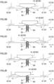
- FIGs. 2A to 2E are used for explaining the movement of a slider 41, 42 in the axial direction in the transmission 1 of the Second Embodiment.
- the transmission 1 shown in FIGs. 2A to 2E is a specific example of the transmission 1 shown in FIG. 1 .
- a slider 40 (41, 42) has two cam surfaces 71 that are spaced apart from each other in the axial direction.
- Each cam surface 71 is tilted relative to the axial direction so that the outermost end in the axial direction of the slider 41, 42 is farthest in the radial direction from the output shaft 12.
- the slider 41 is at a standby position shown in FIG. 2A , when the slider 41 is connected to neither the first speed gear 31 nor the third speed gear 33.
- the slider 42 is at a standby position shown in FIG. 2A , when the slider 42 is connected to neither the second speed gear 32 nor the fourth speed gear 34.
- the cam biasing mechanism 80 is positioned between the two cam surfaces 71 in the axial direction.
- the shift fork 131, 132 by the shift fork 131, 132, it is possible to move the slider 41, 42 from the standby position shown in FIG. 2A to the position shown in FIG. 2B or the position shown in FIG. 2D in the axial direction.
- the cam biasing mechanism 80 makes contact with the cam surface 71.
- the elastic force exerted in the radial direction of the output shaft 12 by the cam biasing mechanism 80 is converted by the cam surface 71 to a force acting on the slider 41, 42 in the direction away from the standby position in the axial direction.
- the slider 41, 42 having been moved to the position shown in FIG. 2B by the shift fork 131, 132 is movable rightward in the axial direction to the position shown in FIG. 2C by the above-described force acting away from the standby position, without needing the help of the shift fork 131, 132.
- the slider 41, 42 having been moved to the position shown in FIG. 2D by the shift fork 131, 132 is movable leftward in the axial direction to the position shown in FIG. 2(e) by the above-described force acting away from the standby position, without needing the help of the shift fork 131, 132.
- the slider 41, 42 when a torque transmitted to the transmission is changed from a drive torque to a coast torque, the slider 41, 42 may be required to be moved from a drive meshed position to a coast meshed position that is far from the standby position as compared to the drive meshed position.
- this requirement is satisfied by moving the slider 41, 42 from the standby position to the drive meshed position by the shift fork 131, 132 and then moving the slider from the drive meshed position to the coast meshed position by the cam biasing mechanism 80. It is noted that the state shown in FIG. 2C and FIG.
- FIG. 2(e) is a state in which the slider 41, 42 is at the coast meshed position.
- the state shown in FIG. 2B and FIG. 2D may be a state in which the slider 41, 42 is at the drive meshed position.
- the state shown in FIG. 2B and FIG. 2D may be a state in which the slider 41, 42 is at a position between the drive meshed position and the coast meshed position, when shift down is being performed.
- FIG. 3A shows a cam biasing mechanism 80 of the transmission 1 of the Third Embodiment.
- the transmission 1 of the Third Embodiment has the same features as the transmission 1 of the First Embodiment.
- the cam biasing mechanism 80 includes contact members 82, in addition to springs 81 and one support member 83.
- the contact member 82 makes contact with a cam surface 71.
- the contact member 82 is at least partially provided in the communication hole 120.
- the contact member 82 accommodates at least part of the spring 81. While the contact member 82 accommodates the entirety of the spring 81 in FIG. 3A , the contact member 82 may only partially accommodate the spring 81.
- the contact member 82 is in contact with the leading end in an elongation-contraction direction of the spring 81.
- the contact member 82 may be joined with the spring 81.
- the contact member 82 may be in contact with the spring 81 without being joined with the spring 81.
- the position of the contact member 82 changes in the radial direction of the power transmission shaft 10.
- the contact member 82 when the spring 81 maximally contracts in the transmission 1, the contact member 82 may be partially positioned in the lubricating oil passage 119.
- the contact member 82 is long as compared to a case where the contact member 82 is not positioned in the lubricating oil passage 119 at all when the spring 81 maximally contracts in the transmission 1 and the length of the communication hole 120 is identical with the length in the arrangement. It is therefore possible to further elongate the spring 81 even when the entirety of the spring 81 is accommodated in the contact member 82.
- the contact member 82 When the spring 81 maximally contracts in the transmission 1, the contact member 82 may not be positioned in the lubricating oil passage 119 at all.
- FIG. 3B shows an example of a cam biasing mechanism 80 of the transmission 1 of the Fourth Embodiment.
- the transmission 1 of the Fourth Embodiment is structurally identical with the transmission 1 of the First Embodiment.
- the cam biasing mechanism 80 includes balls 182, in addition to springs 81 and one support member 83.
- the ball 182 makes contact with a cam surface 71.
- the ball 182 is in contact with the leading end in an elongation-contraction direction of the spring 81.
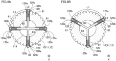
- FIG. 4A shows a cam biasing mechanism 80 of the transmission 1 of the Fourth Embodiment.
- the transmission 1 of the Fifth Embodiment has the same features as the transmission 1 of the First Embodiment.
- the transmission 1 of the Fifth Embodiment may have the same features as the transmission 1 of any one of the Second to Fourth Embodiments.
- the power transmission shaft 10 (the input shaft 11 or the output shaft 12) has four communication holes 120 for one cam biasing mechanism 80.
- the cam biasing mechanism accommodation unit is formed of four communication holes 120. The four communication holes 120 are deviated from each other by about 90 degrees in the circumferential direction of the power transmission shaft 10.
- the cam biasing mechanism 80 includes four springs 81 and one support member 83.
- the support member 83 is cross-shaped. Four leading end portions of the cross-shaped support member 83 are in contact with the respective springs 81.
- the cross-shaped support member 83 may be dividable into plural components.
- FIG. 4B shows a cam biasing mechanism 80 of the transmission 1 of the Sixth Embodiment.
- the transmission 1 of the Sixth Embodiment has the same features as that of the First Embodiment.
- the transmission 1 of the Sixth Embodiment may have the same features as that of any one of the Second to Fourth Embodiments.
- the power transmission shaft 10 (the input shaft 11 or the output shaft 12) has three communication holes 120 for one cam biasing mechanism 80.
- the cam biasing mechanism accommodation unit is formed of three communication holes 120. The three communication holes 120 are deviated from each other by about 120 degrees in the circumferential direction of the power transmission shaft 10.
- the cam biasing mechanism 80 includes three springs 81 and one support member 83.
- the support member 83 is Y-shaped. Three leading end portions of the Y-shaped support member 83 are in contact with the respective springs 81.
- the Y-shaped support member 83 may be dividable into plural components.
- FIG. 5A shows an example of a cam biasing mechanism 80 of the transmission 1 of the Seventh Embodiment.
- FIG. 5B is an enlarged view of part of FIG. 5A .
- FIG. 6A is a cross section taken along the axial direction of part of the transmission 1 of the Seventh Embodiment.
- FIG. 6B is a drawing for illustrating how a cam biasing mechanism 80 and a slider 40 are attached to a power transmission shaft 10.
- the transmission 1 of the Seventh Embodiment has the same features as the transmissions 1 of the First Embodiment and the Third Embodiment.
- the transmission 1 of the Seventh Embodiment may have the same features as the transmission 1 of the Second, Fourth, or Sixth Embodiment.
- a communication hole 120 is circular in shape in a cross section orthogonal to a central axial line C passing through the center of the communication hole 120, in the same manner as in later-described Eighth Embodiment, for example (see FIGs. 7A, 7C, and 7E ).
- the cam biasing mechanism 80 includes two springs 81, two contact members 82, and one support member 83.
- the contact member 82 has a protruding surface section 82a and a cylindrical section 82b.
- the protruding surface section 82a is a portion making contact with a cam surface 71 and is formed as a part of a spherical surface.
- the curvature radius R2 of the protruding surface section 82a is longer than the radius R1 of the communication hole 120.
- the cylindrical section 82b is a cylindrical portion that is substantially identical with the communication hole 120 in radius, and is formed to be integrated with the protruding surface section 82a.
- the contact member 82 has an accommodation space 82c that is formed along the length of the communication hole 120 by the protruding surface section 82a and the cylindrical section 82b.
- the accommodation space 82c accommodates the spring 81.
- the cylindrical section 82b has a bended portion 82b1 that is bended inward in the radial direction of the cylindrical section 82b and is provided at an end portion on the opposite side of the protruding surface section 82a.
- the diameter D1 of an open end 82d that is an end of the contact member 82 on the opposite side of the protruding surface section 82a is shorter than the diameter of a part of the accommodation space 82c, which is formed by the portion of the cylindrical section 82b other than the folder part 82b1.
- the support member 83 is shaped as a rod that is circular in shape in a cross section taken in a direction orthogonal to the central axial line C of the communication hole 120 and extends along a single linear line. Two end portions of the rod-shaped support member 83 are in contact with springs 81, respectively. Each of the two end portions of the support member 83 which are in contact with the springs 81 has a large diameter portion 83a.
- the support member 83 has a portion which is shorter in diameter than the large diameter portion 83a and is positioned to be closer to the power transmission shaft 10 than the large diameter portion 83a is to the power transmission shaft 10. This portion shorter in diameter than the large diameter portion 83a is connected to the large diameter portion 83a. In the example shown in FIGs.
- the large diameter portion 83a is longer in diameter than the remaining portion of the support member 83.
- the diameter D2 of the large diameter portion 83a is substantially identical with a portion of the accommodation space 82c, which is formed of a portion of the cylindrical section 82b different from the bended portion 82b1, and is longer than the diameter D1 of the open end 82d of the contact member 82.
- the large diameter portion 83a is provided at a part of the accommodation space 82c, which is formed of a portion of the cylindrical section 82b different from the bended portion 82b1. With this arrangement, the large diameter portion 83a provided in the accommodation space 82c does not pass through the open end 82d and go out from the accommodation space 82c. To put it differently, the large diameter portion 83a does not come out from the contact member 82, and the contact member 82 is connected to the support member 83.
- the slider 40 of the transmission 1 of the Seventh Embodiment has four cam surfaces 71, two checking grooves 72, and four guide surfaces 73.
- Each checking groove 72 is formed between two cam surfaces 71 that are aligned in the axial direction.
- the checking groove 72 has a spherical surface.
- the slider 40 has two checking grooves 72 corresponding to two contact members 82, the number of checking grooves 72 formed to be aligned in the circumferential direction is not limited to two, and may be three or more.
- the checking grooves 72 may be a single groove which extends in the circumferential direction of the slider 40.
- the checking groove 72 may be curved in shape such as arc-shaped, may be V-shaped, or may be tapered in shape with a flat portion at a central portion, when viewed in a direction orthogonal to the circumferential direction.
- the slider 40 makes contact with a contact member 82 of the cam biasing mechanism 80.
- the contact member 82 of the cam biasing mechanism 80 makes contact with the four cam surfaces 71 and the two checking grooves 72.
- the contact member 82 of the cam biasing mechanism 80 simultaneously makes contact with two cam surfaces 71 aligned in the circumferential direction among the four cam surfaces 71.
- Each cam surface 71 is a tilted surface that is tilted relative to the axial direction, i.e., the cam surface 71 is angled away from the checking groove 72 in the axial direction toward the outer side in the radial direction of the power transmission shaft 10.
- the contact member 82 of the cam biasing mechanism 80 makes contact with the cam surface 71.
- the elastic force of the spring 81 acts as a force of pressing the slider 40 in the axial direction in which the checking groove 72 moves away from the cam biasing mechanism 80.
- the checking groove 72 is formed to allow the contact member 82 of the cam biasing mechanism 80 to be fitted therewith.
- the contact member 82 of the cam biasing mechanism 80 is fitted with the checking groove 72 of the slider 40.
- the elastic force of the spring 81 acts as resistance to the movement in the axial direction of the slider 40 in a state in which the cam biasing mechanism 80 is fitted with the checking groove 72.
- the elastic force of the spring 81 acts as a force moving the slider 40 in the axial direction until the cam biasing mechanism 80 is fitted with the checking groove 72.
- the four guide surfaces 73 correspond to the four cam surfaces 71, respectively, and each guide surface 73 is connected to the outer end in the axial direction of the corresponding cam surface 71.
- Each guide surface 73 is a tilted surface that is tilted relative to the axial direction, i.e., the guide surface 73 is angled away from the checking groove 72 in the axial direction toward the outer side in the radial direction of the power transmission shaft 10.
- the tilt angle of the guide surface 73 relative to the axial direction may be larger than the tilt angle of the cam surface 71 in the axial direction, or may be smaller than the tilt angle of the cam surface 71 relative to the axial direction.
- the cam biasing mechanism 80 of the Seventh Embodiment may be arranged such that, for example, a spring 81 and portions of the support member 83 including the large diameter portion 83a are accommodated in the accommodation space 82c of the contact member 82 in which a bended portion 82b1 is not formed, and then the bended portion 82b1 is formed by bending an end portion of the cylindrical section 82b, which is on the opposite side of the protruding surface section 82a.
- the cam biasing mechanism 80 having been formed is inserted, through one of the two communication holes 120, into the above-described space that is formed by the two communication holes 120 and part of the lubricating oil passage 119 and extends along one linear line that is in parallel to the radial direction of the power transmission shaft 10, and the cam biasing mechanism 80 is then attached to the power transmission shaft 10 as the slider 40 is moved along the axial direction.
- the cam biasing mechanism 80 is arranged so that the large diameter portion 83a of the support member 83 is in contact with the bended portion 82b1 of the cylindrical section 82b on account of the elastic force of the spring 81, and the length in the radial direction of the power transmission shaft 10 is L3 even if the springs 81 are different in length.
- the contact member 82 makes contact with the guide surface 73, the cam surface 71, and the checking groove 72 in this order, with the result that the spring 81 is contracted and the contact member 82 moves inward in the radial direction of the power transmission shaft 10.
- the contact member 82 is fitted with the checking groove 72. With this, the attachment of the slider 40 to the power transmission shaft 10 is completed.
- the cam biasing mechanism 80 and the slider 40 can be easily attached to the power transmission shaft 10. Furthermore, before the slider 40 is attached, the length of the cam biasing mechanism 80 in the radial direction of the power transmission shaft 10 is L3 irrespective of the lengths of the springs 81. On this account, the tilt angle of the guide surface 73 relative to the axial direction can be easily set.
- FIG. 6B shows a case where the slider 40 is attached to the power transmission shaft 10 from the right side in FIG. 6B
- the slider 40 may be attached to the power transmission shaft 10 from the left side in FIG. 6B .
- the support member 83 has an oil hole 83b.
- the oil hole 83b has a first hole portion 83b1 and a second hole portion 83b2.
- the first hole portion 83c is formed along the central axial line C of the communication hole 120.
- the both ends in the longitudinal direction of the first hole portion 83b1 are open and face the springs 81.
- the second hole portion 83b2 connects a central portion in the longitudinal direction of the first hole portion 83b1 with the lubricating oil passage 119.
- the lubricating oil flows from the lubricating oil passage 119 into the second hole portion 83b2, and the lubricating oil having flown into the second hole portion 83b2 flows in the first hole portion 83b1 toward the springs 81.
- the load on the cam surface 71 from the cam biasing mechanism 80 is not only the elastic force of the spring 81 but also the pressure of the lubricating oil.
- the support member 83 has the oil hole 83b, the lubricating oil flows equally toward the two springs 81, with the result that the two cam surfaces 71 are equally pressurized by the lubricating oil.
- the number of the contact members 82 in the cam biasing mechanism 80 may be three or more.
- the curvature radius R2 of the protruding surface section 82a may be equal to or shorter than the radius R1 of the communication hole 120.
- the cylindrical section 82b may not have the bended portion 82b1, and the portion of the accommodation space 82c formed of the cylindrical section 82b may be substantially constant in diameter.
- the support member 83 may not have the large diameter portion 83a.
- the contact member 82 in which at least part of the spring 81 is accommodated may not have the protruding surface section 82a and the cylindrical section 82b.
- the support member 83 may not have the oil hole 83b.
- the slider 40 may not have the checking groove 72.
- the two guide surfaces 73 on the right side in FIG. 6B among the four guide surfaces 73 of the slider 40 may not be provided.
- the two guide surfaces 73 on the left side in FIG. 6B among the four guide surfaces 73 of the slider 40 may not be provided.
- the slider 40 may not have the guide surface 73.
- the transmission 1 of the Eighth Embodiment has the same features as the transmissions 1 of the First Embodiment and Third Embodiment.
- the transmission of the Eighth Embodiment may have the same features as the transmission 1 of the Second and Fourth to Seventh Embodiments.
- a spline on which recesses 102 and protrusions 101 are alternately provided in the circumferential direction is formed on the outer circumferential surface of at least one power transmission shaft 10 (the input shaft 11 or the output shaft 12).
- the slider 40 is fitted with the spline to be movable in the axial direction.
- the communication hole 120 is circular in shape in a cross section orthogonal to the central axial line C passing through the center of the communication hole 120. Furthermore, the communication hole 120 is formed so that the center of the communication hole 120 passes through a recess 102 or a protrusion 101.
- the communication hole 120 may be formed so that the center of the communication hole 120 passes through the center in the circumferential direction of a recess 102 or a protrusion 101.
- FIG. 7A shows an example of part of the outer circumferential surface of the power transmission shaft 10 when the center of the communication hole 120 passes through a recess 102.
- FIG. 7B is a cross section taken along a Y-Y line in FIG. 7A .
- the spline has cutouts 103 with which the two protrusions 101 neighboring the recess 102 passing through the center of the communication hole 120 form a counterbored shape.
- the cutouts 103 are formed at the two protrusions 101, respectively.
- the two cutouts 103 are formed along parts of the outer circumferential surface of the contact member 82. At least part of the two cutouts 103 is formed as part of the inner circumferential surface of a virtual cylindrical body that is centered on the central axial line C passing through the center of the communication hole 120.
- FIG. 7C shows another example of part of the outer circumferential surface of the power transmission shaft 10 when the center of the communication hole 120 passes through a recess 102.
- FIG. 7D is a cross section taken along an X1-X2 line in FIG. 7C .
- the spline has cutouts 104 with which the two protrusions 101 neighboring the recess 102 passing through the center of the communication hole 120 form a countersunk shape in the axial direction.
- the cutouts 104 are formed at the two protrusions 101, respectively.
- Each of the two cutouts 104 is narrowed (tapered) inward in the radial direction of the power transmission shaft 10 (the input shaft 11 or the output shaft 12) in a cross section taken along the axial direction.
- Each cutout 104 may have a flat surface and/or a curved surface.
- FIG. 7E shows an example of part of the outer circumferential surface of the power transmission shaft 10 when the center of the communication hole 120 passes through the protrusion 101.
- FIG. 7F is a cross section taken along an X2-X2 line in FIG. 7E .
- the spline has cutouts 105 with which the protrusion 101 passing through the center of the communication hole 120 forms a countersunk shape in the axial direction.
- One cutout 105 is formed at each of the ends in the axial direction of the communication hole 120.
- Each of the two cutouts 105 is narrowed (tapered) inward in the radial direction of the power transmission shaft 10 (the input shaft 11 or the output shaft 12) in a cross section taken along the axial direction.
- Each cutout 105 may have a flat surface and/or a curved surface.
- FIGs. 7(a) to 7(f) show mere examples, and the lengths in the circumferential direction of the protrusion 101 and the recess 102, the diameter of the communication hole 120, the diameter of the contact member 82, and the curvature radius of the contact member 82 are not limited to those in the examples shown in FIGs. 7(a) to 7(f).
- the diameter of the communication hole 120 may be equal to or shorter than the width of the recess 102 passing through the center of the communication hole 120 in the example shown in FIG. 7A and FIG. 7B .
- the diameter of the communication hole 120 may be equal to or shorter than the width of the recess 102 passing through the center of the communication hole 120 in the example shown in FIG. 7C and FIG. 7D .
- the diameter of the communication hole 120 may be equal to or shorter than the width of the protrusion 101 passing through the center of the communication hole 120 in the example shown in FIG. 7E and FIG. 7F.
- the transmission 1 of the Ninth Embodiment is a specific example of the transmission 1 of the First Embodiment shown in FIG. 1 . It is, however, noted that the cam biasing mechanism 80 of the Seventh Embodiment is employed as the cam biasing mechanism 80 of the present embodiment.
- the transmission 1 of the Ninth Embodiment is mounted on, for example, a vehicle (not illustrated) such as a motorcycle.
- vehicle includes a driving source 5 (see FIG. 1 ) such as an engine, the transmission 1, a clutch 2, and a controller (not illustrated).
- the driving force generated by the driving source 5 is transmitted to a wheel that is a driving target 4 (see FIG. 1 ), through the clutch 2 and the transmission 1.
- the controller controls the driving source 5, the transmission 1, and the clutch 2.
- the transmission 1 is configured to be able to transmit power of the input shaft 11 to the output shaft 12.
- the ratio of the rotational speed of the input shaft 11 to the rotation speed of the output shaft 12 is termed a transmission ratio.
- the transmission 1 has plural speed stages (gear positions) that are different in transmission ratio.
- the speed stage of the transmission 1 is changed by the controller.
- the vehicle may include a shift operator (not illustrated) that is operated by the driver to change the speed stage of the transmission 1.
- the controller changes the speed stage of the transmission 1 in accordance with an operation of the shift operator.
- the controller may be arranged to be able to automatically change the speed stage of the transmission 1 in accordance with, for example, the vehicle speed, when the shift operator is not operated.
- the vehicle may not include a shift operator that is operated by the driver to change the speed stage of the transmission 1.
- the input shaft 11 is connected to the driving source 5 through the clutch 2.
- the driving source 5 is an engine
- the input shaft 11 is connected to the crankshaft of the engine.
- the clutch 2 is a friction clutch, for example, but is not limited to this.
- the clutch 2 is not a dual clutch.
- the transmission 1 is not a dual clutch transmission.
- the transmission 1 is an AMT (Automated Manual Transmission).
- the controller is arranged to be able to automatically change the power transmission ratio of the clutch 2 without requiring an operation by the driver.
- the controller may control at least one of the clutch 2 or the engine (driving source 5) when changing the speed stage of the transmission 1.
- the transmission 1 includes three slide gears 41, 42, and 43.
- the following will describe an arrangement in which the shift gears 31 to 36 are connected to the slide gears 41, 42, and 43.
- the slide gear 41 has dogs 51 that are provided at an end portion opposing the first speed gear 31 in the axial direction.
- the first speed gear 31 has dogs 61 that are connectable with the dogs 51 of the slide gear 41 by meshing therewith.
- the slide gear 41 has dogs 53 that are provided at an end portion opposing the third speed gear 33 in the axial direction.
- the third speed gear 33 has dogs 63 that are connectable with the dogs 53 of the slide gear 41 by meshing therewith.
- the slide gear 42 has dogs 52 that are provided at an end portion opposing the second speed gear 32 in the axial direction.
- the second speed gear 32 has dogs 62 that are connectable with the dogs 52 of the slide gear 42 by meshing therewith.
- the slide gear 42 has dogs 54 that are provided at an end portion opposing the fourth speed gear 34 in the axial direction.
- the fourth speed gear 34 has dogs 64 that are connectable with the dogs 54 of the slide gear 42 by meshing therewith.
- the slide gear 43 has dogs 55 that are provided at an end portion opposing the fifth speed gear 35 in the axial direction.
- the fifth speed gear 35 has dogs 65 that are connectable with the dogs 55 of the slide gear 43 by meshing therewith.
- the slide gear 43 has dogs 56 that are provided at an end portion opposing the sixth speed gear 36 in the axial direction.
- the sixth speed gear 36 has dogs 66 that are connectable with the dogs 56 of the slide gear 43 by meshing therewith.
- each of the slide gears 41, 42, and 43 is meshed with one of the shift gears 31 to 36 adjacent to the each slide gear in the axial direction, by means of the dogs.
- one of the shift gears 31 to 36 is meshed with a slide gear adjacent to the one shift gear in the axial direction by means of the dogs, power is transmitted from the input shaft 11 to the output shaft 12 through that shift gear and that slide gear.
- the first speed gear 31 is meshed with the slide gear 41
- the power from the input shaft 11 is transmitted to the gear 21, the first speed gear 31, the slide gear 41, and then the output shaft 12 in order.
- the speed stage of the transmission 1 in this case is the first speed stage.
- the speed stage of the transmission 1 in this case is the third speed stage.
- the speed stage of the transmission 1 in this case is the fifth speed stage.
- the transmission 1 is in a neutral state.
- the speed stage of the transmission 1 is controlled. In other words, the slide gears 41, 42, and 43 are driven in the axial direction in order to change the speed stage.
- the dogs 51 are aligned in the circumferential direction.
- the dogs 52 to 56 and 61 to 66 are also aligned in the circumferential direction.
- the dogs 51 to 56 of the slide gears 41, 42, and 43 are dog teeth. In other words, the dogs 51 to 56 are formed to protrude in the axial direction.
- the dogs 61 to 64 of the shift gears 31 to 34 are dog holes.
- the dogs 61 to 64 are concave in shape. In other words, the dogs 61 to 64 are dog holes that do not penetrate the shift gears 31 to 34 in the axial direction.
- the dogs 61 to 64 may be dog holes penetrating the shift gears 31 to 36 in the axial direction.
- the dogs 61 to 64 may be dog teeth. In this case, the dogs 51 to 54 may be dog teeth or dog holes.
- the dogs 65 and 66 of the shift gears 35 and 36 are dog teeth.
- the dogs 65 and 66 may be dog holes.
- FIG. 9A to FIG. 9E are developed sectional views of the second speed gear 32 and the slide gear 42.
- the up-down direction in each of FIG. 9A to FIG. 9E indicates the circumferential direction about the rotational central axis of the output shaft 12.
- the rotational direction of each of the shift gear 32 and the slide gear 42 is an upward direction in FIG. 9A to FIG. 9E.
- FIG. 9A shows a state in which the transmission 1 is at a speed stage different from the second speed stage or at the neutral position.
- the arrows in FIG. 9B and FIG. 9C show the direction of the torque generated in the shift gear 32.
- the arrows in FIG. 9D and FIG. 9E show the rotational direction of the slide gear 42 relative to the shift gear 32 and the rotational direction of the shift gear 32 relative to the slide gear 42.
- the dog (dog tooth) 52 has a drive meshing surface 57, a coast meshing surface 58, and a release guide surface 59.
- the drive meshing surface 57 is close to the tip of the teeth as compared to the coast meshing surface 58.
- the drive meshing surface 57 is tilted in the circumferential direction relative to the axial direction.
- the drive meshing surface 57 is tilted so that one end of the surface close to the bottom of the teeth is on the downstream in the rotational direction of the shift gear 32 and the slide gear 42 as compared to the other end of the surface far from the bottom of the teeth.
- the drive meshing surface 57 may be formed to extend along the axial direction.
- the coast meshing surface 58 is tilted in the circumferential direction relative to the axial direction.
- the coast meshing surface 58 is tilted so that one end of the surface close to the tip of the teeth is on the downstream in the rotational direction of the shift gear 32 and the slide gear 42 as compared to the other end of the surface far from the tip of the teeth.
- the coast meshing surface 58 may be formed to extend along the axial direction.
- the release guide surface 59 is aligned with the drive meshing surface 57 in the circumferential direction.
- the release guide surface 59 is tilted in the axial direction relative to the circumferential direction.
- the release guide surface 59 may be spiral in shape relative to the rotational central axis of the output shaft 12, or may extend along the radial direction.
- the dog (dog hole) 62 has a drive meshing surface 67, a coast meshing surface 68, and a movement guiding surface 69.
- the tilt angle and the tilting direction of the drive meshing surface 67 relative to the axial direction are identical with those of the drive meshing surface 57 of the dog 52.
- the tilt angle and the tilting direction of the coast meshing surface 68 relative to the axial direction are identical with those of the coast meshing surface 58 of the dog 52.
- the movement guiding surface 69 is tilted in the axial direction relative to the circumferential direction.
- the movement guiding surface 69 may be spiral in shape relative to the rotational central axis of the output shaft 12, or may extend along the radial direction.
- FIG. 9B shows a state in which the drive meshing surface 57 is in contact with the drive meshing surface 67 and the dog 52 is meshed with the dog 62.
- This meshed state will be referred to as a drive meshed state.
- the position in the axial direction of the slide gear 42 when the slide gear 42 and the shift gear 32 are in the drive meshed state will be referred to as the drive meshed position of the slide gear 42 relative to the shift gear 32.
- the term "drive meshed position" is used no matter whether the drive meshed state is established.
- FIG. 9C shows a state in which the coast meshing surface 58 is in contact with the coast meshing surface 68 and the dog 52 is meshed with the dog 62.
- This meshed state will be referred to as a coast meshed state.
- the dogs 52 and 62 are deeply meshed with each other as compared to the drive meshed state.
- the position in the axial direction of the slide gear 42 when the slide gear 42 and the shift gear 32 are in the coast meshed state will be referred to as the coast meshed position of the slide gear 42 relative to the shift gear 32. It is noted that the term "coast meshed position" is used no matter whether the coast meshed state is established.
- the coast torque is a torque generated by the rotational inertia of the wheel and is exerted in the direction opposite to the drive torque.
- the coast torque is a torque transmitted between the engine and the wheel.
- the coast torque is generated when, for example, engine braking is performed.
- FIG. 9D shows a state in which an edge of the dog (dog tooth) 52 is in contact with the movement guiding surface 69.
- the slide gear 42 receives a force acting away from the shift gear 32.
- the transmission 1 is at the second speed stage and the torque transmitted to the transmission 1 is switched from the coast torque to the drive torque, the slide gear 42 rotates at a lower speed than the shift gear 32.
- FIG. 9E shows a state in which the edge of the dog (dog hole) 62 is in contact with the release guide surface 59.
- the edge of the dog 62 makes contact with the release guide surface 59 while the slide gear 42 rotates at a higher speed than the shift gear 32
- the slide gear 42 receives a force acting away from the shift gear 32.
- the release guide surface 59 is used when the speed is changed.
- Each of the dogs 51 to 54 of the slide gears 41 and 42 has the release guide surface 59, whereas each of the dogs 61 to 64 of the shift gears 31 to 34 has the movement guiding surface 69.
- Each of the dogs of the slide gears 41 and 42 may have both the movement guiding surface and the release guide surface as in the dog of the slider of Patent Literature 1.
- the dog 54 of the slide gear 42 may not have the release guide surface 59.
- Each of the dogs 64 of the fourth speed gear 34 and the dogs 54 of the slide gear 42 may not have the movement guiding surface.
- the shape of each of the dogs 64 of the fourth speed gear 34 and the dogs 54 of the slide gear 42 may be identical with the shape of each of the dogs 65 and 66 of the shift gears 35 and 36 and the dogs 55 and 56 of the slide gear 43.
- the transmission 1 is arranged so that, when shifting up, the transmission 1 is temporarily in a double-meshed state where the two slide gears 41 and 42 are simultaneously meshed with two of the shift gears 31 to 34 through dogs. For example, when shifting up from the first speed stage to the second speed stage, the transmission 1 is temporarily in the double-meshed state where the two slide gears 41 and 42 are simultaneously meshed with the shift gears 31 and 32 through the dogs 51, 52, 61, and 62. When the slide gear 42 is meshed with the second speed gear 32 through the dogs 52 and 62, the slide gear 41 rotates at a higher speed than the first speed gear 31.
- the transmission 1 is arranged so that the movement of the slide gear 41 in the axial direction toward the first speed gear 31 is restricted in this case.
- the release guide surface 59 of the dog 51 of the slide gear 41 makes contact with the dog 61 of the first speed gear 31 and hence the slide gear 41 moves away from the first speed gear 31 in the axial direction. Due to this, the meshing between the dog 51 of the slide gear 41 and the dog 61 of the first speed gear 31 is canceled.
- the controller is not required to control the clutch 2 and the engine in order to reduce the pressing force generated in accordance with the power transmission between the dog 51 of the slide gear 41 and the dog 61 of the first speed gear 31.
- the transmission 1 is arranged so that a force of canceling the meshing of the dogs is generated in one of the two slide gears 41 and 42, when the double-meshed state is established.
- the transmission 1 is therefore able to seamlessly perform shift up to the second speed stage without blocking the power transmission.
- the transmission 1 is able to seamlessly perform shift up to the third speed stage and the fourth speed stage without blocking the power transmission.
- the transmission 1 is arranged so that the double-meshed state is not established when shifting down.
- the slide gears 41 and 42 may be different from one another in shape, as long as they share the below-described common characteristics.
- the slide gears 41 and 42 may be symmetrical in shape.
- the slide gear 42 is spline-fitted with the output shaft 12. As shown in FIG. 8 , in the inner circumferential surface of the slide gear 42, four cam surfaces 71 and two checking grooves 72 are formed in the same manner as in the Seventh Embodiment. The checking groove 72 may not be formed. On the slide gear 42, a guide surface 73 similar to that described in the Seventh Embodiment may or may not be formed.
- the cam surface 71 is a tilted surface that is tilted relative to the axial direction, i.e., the cam surface 71 is angled away from the checking groove 72 in the axial direction toward the outer side in the radial direction of the output shaft 12.
- the contact member 82 of the cam biasing mechanism 80 makes contact with the cam surface 71.
- the elastic force of the spring 81 acts as a force of pressing the slide gear 42 in the axial direction in which the checking groove 72 moves away from the cam biasing mechanism 80.
- the checking groove 72 is formed to allow the contact member 82 of the cam biasing mechanism 80 to be fitted therewith.
- the contact member 82 of the cam biasing mechanism 80 is fitted with the checking groove 72 of the slide gear 42.
- the elastic force of the spring 81 acts as resistance to the movement in the axial direction of the slide gear 42 in a state in which the cam biasing mechanism 80 is fitted with the checking groove 72.
- the elastic force of the spring 81 acts as a force moving the slide gear 42 in the axial direction until the slide gear pressing member 80 is fitted with the checking groove 72.
- the slide gears 41, 42, and 43 move in the axial direction as the shift forks 131, 132, and 133 move in the axial direction.
- the shift forks 131, 132, and 133 are included in a shift mechanism in which the slide gears 41, 42, and 43 are moved by the shift forks 131, 132, and 133.
- the shift mechanism includes an unillustrated shift actuator that is controlled by the controller. As the controller controls the shift actuator, the shift forks 131, 132, and 133 move in the axial direction.
- the structure of the shift mechanism is not particularly limited.
- the shift mechanism may be a mechanism including a shift drum, for example.
- parts of the shift forks 131, 132, and 133 may be provided in grooves formed in the shift drum, respectively.
- parts of components connected to the shift forks 131, 132, and 133 so as to move in the axial direction together with the shift forks 131, 132, and 133 may be provided in grooves formed in the shift drum.
- a mechanism in which the shift drum is rotated by the shift actuator is not particularly limited.
- the shift mechanism may not include a shift drum.
- the transmission 1 may be a sequential manual transmission. In other words, the transmission 1 may be arranged so that, when the speed (gear position) is changed, the speed is changeable to only a speed that is adjacent to the speed before the change in terms of the transmission ratio.
- the transmission 1 is a six-speed transmission.
- the transmission 1 of the Ninth Embodiment is a six-speed transmission, too.
- the transmission of the present teaching is not limited to a six-speed transmission.
- the transmission 1 of the Ninth Embodiment is arranged so that, at the time of shift up to the second speed stage, shift up to the third speed stage, and shift up to the fourth speed stage, a double-meshed state is temporarily established, whereas, at the time of shift up to the fifth speed stage and shift up to the sixth speed stage, the double-meshed state is not established.
- the transmission of the present teaching is a six-speed transmission
- the speed stage after the completion of shift up with which the double-meshed state is temporarily established may not be the second speed stage, the third speed stage, or the fourth speed stage.
- the transmission of the present teaching is arranged so that the double-meshed state is temporarily established when shifting up to at least one speed stage.
- two slide gears may be provided in place of the slide gear 43.
- the transmission 1 may be arranged so that the double-meshed state is temporarily established when shifting up to the fifth speed stage or shifting up to the sixth speed stage.
- plural cam surfaces 71 and a checking groove 72 may be provided in the slide gear for the fifth speed stage.
- plural communication holes 120 are formed and a cam biasing mechanism 80 is provided.
- the number of the communication holes 120 formed in the input shaft 11 may be identical with the number of cam surfaces 71 in the slide gear for the fifth speed stage.
- These two slide gears may have dogs that are provided at end portions opposing the shift gears 35 and 36 in the axial direction and have a common feature as the dogs 51 to 54.
- the dogs 65 and 66 of the shift gears 35 and 36 may have a common feature as the dogs 61 to 64 of the shift gears 31 to 34.
Landscapes
- Engineering & Computer Science (AREA)
- General Engineering & Computer Science (AREA)
- Mechanical Engineering (AREA)
- General Details Of Gearings (AREA)
- Structure Of Transmissions (AREA)
Abstract
Description
- The present teaching relates to a transmission capable of performing seamless shift up.
- A transmission capable of performing seamless shift up has been known. The transmission includes an input shaft connected to a driving source and an output shaft connected to a driving target. On the input shaft and the output shaft, shift gears are provided to be rotatable relative to one another. The shift gears are provided to correspond to speed stages in number, and are arranged so that transmission ratios are different between the speed stages. The transmission allows selection of a shift gear that is rotated together with the input shaft or the output shaft. Through the selected shift gear, power is transmitted from the input shaft to the output shaft.
- For example,
Patent Literature 1 discloses a transmission which is capable of performing seamless shift up. The transmission ofPatent Literature 1 is arranged so that, when shifting up, two sliders are temporarily connected to the shift gear at the same time. In the transmission ofPatent Literature 1 in this state, a force in an axial direction is generated to cancel the connection of one of the two sliders. With this arrangement, seamless shift up is achieved without interrupting the transmission of power. In addition to this, the transmission ofPatent Literature 1 is provided with a cam biasing mechanism that is provided on each of an input shaft and an output shaft so as to make contact with a cam surface on the slider. As the cam biasing mechanism is pressed onto the cam surface of the slider, the slider receives a force acting toward the shift gear. When a torque transmitted to the transmission is changed from a drive torque to a coast torque, the slider can be moved by the cam biasing mechanism from a drive meshed position to a coast meshed position. - [Patent Literature 1] International Publication No.
2020/250535 - A cam biasing mechanism of
Patent Literature 1 is formed of a ball and a coil spring. A part of the ball and a majority of the coil spring are accommodated in a clutch hub that is provided at the outer circumferences of the input shaft and the output shaft, in order to exert an elastic force of the coil spring to the ball. End portions of the coil spring are fitted into recesses formed in outer circumferential surfaces of the input shaft and the output shaft, respectively. The ball protrudes from the clutch hub and is in contact with a cam surface formed on a slider. As the ball makes contact with the cam surface, a radial force exerted to the cam surface is converted to a force acting in the axial direction of the input shaft and the output shaft. To put it differently, the ball of the cam biasing mechanism makes contact with the cam surface and presses the slider in the axial direction, with the result that the slider is moved. - To improve the elastic force exerted to the cam surface of the slider, the number of springs of the cam biasing mechanism may be increased or each spring of the cam biasing mechanism may be elongated. However, when the number of springs is increased, the strength and rigidity of the input shaft and the output shaft are deteriorated because the number of the recesses formed in the outer circumferential surfaces of the input shaft and the output shaft is increased. When each spring is elongated, the transmission is disadvantageously upsized because the cam biasing mechanism is upsized.
- An object of the present teaching is to increase the elastic force of a spring of a cam biasing mechanism when the spring is in contact with a cam surface and presses a slider in an axial direction and to downsize a transmission capable of performing seamless shift up, while maintaining both the strength and rigidity of an input shaft and an output shaft.
- The transmission comprises: an input shaft connected to a driving source and an output shaft connected to a driving target, on the input shaft and the output shaft, shift gears being provided to be each rotatable relative to the input shaft or the output shaft and immovable in an axial direction of the input shaft and the output shaft, the shift gears corresponding to speed stages in number, on the input shaft and the output shaft, sliders being provided to be each rotatable together with the input shaft or the output shaft, movable in the axial direction of the input shaft and the output shaft by a shift fork, and connectable to at least one of the shift gears, two of the sliders being temporarily in a state of being connected simultaneously with two of the shift gears when shifting up, and when the state of being simultaneously connected is established, a force of canceling connection of one of the two sliders being generated, at least one cam biasing mechanism being provided on at least one of the input shaft or the output shaft to impart an elastic force to at least one of the sliders in a radial direction of the input shaft or the output shaft, the at least one of the sliders having cam surfaces each of which is arranged to convert the elastic force exerted in the radial direction by the cam biasing mechanism into a force acting in the axial direction, power being transmitted from the input shaft to the output shaft through one of the shift gears connected to one of the sliders moved by the shift fork, at least one of the input shaft or the output shaft including: a lubricating oil passage which is formed along the axial direction and allows lubricating oil to flow in the lubricating oil passage; and at least one cam biasing mechanism accommodation unit each of which accommodates part of the at least one cam biasing mechanism, the cam biasing mechanism accommodation unit being formed of communication holes each of which has an opening portion formed in an outer circumferential surface of the input shaft or the output shaft and is connected to the lubricating oil passage at an end on the opposite side of the opening portion, and when, in a cross section orthogonal to the axial direction, ends of the opening portion of each of the communication holes formed in the outer circumferential surface of the input shaft or the output shaft are opening edges, each of the communication holes is formed so that a first arc that is an arc between the opening edges neighboring each other in the circumferential direction of the outer circumferential surface and excludes the opening portion of any of the communication holes being longer than a second arc that is an arc between the opening edges at the respective ends of one of the communication holes, and the cam biasing mechanism including: springs at least part of each of which is provided in the communication holes each of which is formed so that the first arc is longer than the second arc, each of the springs being configured to impart the elastic force to the cam surfaces of the slider; and a support member which is at least partially provided in the lubricating oil passage so that the support member is in contact with the springs and intersects with the lubricating oil passage.
- According to this arrangement, at least part of the spring constituting the cam biasing mechanism is provided in the communication hole formed in the input shaft or the output shaft. In other words, the spring is at least partially accommodated in the input shaft or the output shaft. Because the communication hole is formed inside the input shaft or the output shaft, the length in the radial direction of the hole accommodating the spring can be easily elongated as compared to a case where a hole accommodating a spring is formed in a component provided on the outer circumference of the input shaft or the output shaft. It is therefore easy to ensure the spring to be sufficiently long and have a sufficient elastic force.
- Furthermore, according to the arrangement above, because the spring is at least partially provided in the communication hole connected to the lubricating oil passage at an end on the opposite side of the opening portion, the spring can be elongated as compared to a case where the spring is at least partially provided in a recess that has an opening portion in the outer circumferential surface of at least one of the input shaft or the output shaft and does not communicate with the lubricating oil passage. This arrangement makes it possible to secure the elastic force of the spring even if the communication hole is short in diameter.
- If, being different from the arrangement above, the spring is partially provided in the lubricating oil passage so that the spring intersects with the lubricating oil passage, a part of the spring which is inside the lubricating oil passage tends to be deformed in a direction different from the elongation-contraction direction, e.g., in the axial direction. In this regard, in the arrangement above, the support member is at least partially provided in the lubricating oil passage so that the support member intersects with the lubricating oil passage. On this account, the deformation of the spring in a direction different from the elongation-contraction direction is suppressed and hence the spring can smoothly elongate and contract, with the result that the elastic force of the spring is ensured.
- Furthermore, in the cross section orthogonal to the axial direction, the communication hole in which at least part of the spring is provided is formed so that the length of the first arc at the outer circumferential surface of the input shaft or the output shaft is longer than the second arc. This arrangement makes it possible to secure both the strength and rigidity of the input shaft and the output shaft in which the spring is at least partially accommodated in the communication hole. Furthermore, because the communication hole is formed inside at least one of the input shaft or the output shaft, the transmission is downsized in the axial direction and the radial direction, because, as compared to a case where a communication hole is formed in a component provided on the outer circumference of at least one of the input shaft or the output shaft, such a component is not required. It is therefore possible to downsize the transmission.
- As described above, in the transmission of the present teaching, it is possible to perform seamless shift up and to increase the elastic force of the spring of the cam biasing mechanism when the spring is in contact with the cam surface and presses the slider in the axial direction, while maintaining both the strength and rigidity of the input shaft and the output shaft.
- (2) In addition to the arrangement (1) above, the transmission of the embodiment of the present teaching may be arranged as described below.
- Each of the sliders is configured to be moved in the axial direction by the shift fork from a standby position where the slider is unconnected to the shift gear, and each of the cam surfaces converts the elastic force exerted in the radial direction by the cam biasing mechanism to a force which is exerted in the axial direction to move a slider having the cam surface in a direction opposite to a direction toward the standby position from a position to which the slider is moved by the shift fork.
- According to this arrangement, without using the shift fork, the slider can be moved away from the standby position from a position to which the slider has been moved by the shift fork, by an elastic force of the cam biasing mechanism.
- In a transmission capable of performing seamless shift up as in
Patent Literature 1, when, for example, a torque transmitted to the transmission is changed from a drive torque to a coast torque, the slider may be required to be moved from a drive meshed position to a coast meshed position. The above-described arrangement makes it possible to deal with such a case. - (3) In addition to the arrangement (1) or (2) above, the transmission of the embodiment of the present teaching may be arranged as described below.
- The cam biasing mechanism accommodation unit is formed of two communication holes formed along a single linear line intersecting with a central axial line of the input shaft or the output shaft, and the at least one of the sliders has two cam surfaces which simultaneously receive the elastic force from the cam biasing mechanism.
- According to this arrangement, it is possible to provide the support member along one linear line across the two communication holes and the lubricating oil passage. Furthermore, in the arrangement described above, as the cam biasing mechanism, which includes two springs corresponding to the respective two communication holes and the support member, is inserted from one side of the two communication holes, it is possible to provide the cam biasing mechanism in a space that is along one linear line extending across the two communication holes and the lubricating oil passage. This makes it easy to attach the cam biasing mechanism to at least one of the input shaft or the output shaft. Furthermore, the cam biasing mechanism is structurally simple, and the support member can be shortened. When the support member is shortened, it is easy to arrange the spring to be sufficiently long and have a sufficient elastic force.
- In addition to the above, because one cam biasing mechanism accommodation unit is formed of two communication holes, the strength and rigidity of at least one of the input shaft or the output shaft can be improved as compared to a case where one cam biasing mechanism accommodation unit is formed of three or more communication holes.
- (4) In addition to any one of the arrangements (1) to (3) above, the transmission of the embodiment of the present teaching may be arranged as described below.
- The cam biasing mechanism includes contact members each of which accommodates at least part of each of the springs, each of which is at least partially provided in the communication hole, and each of which makes contact with a cam surface.
- According to this arrangement, the spring can be further elongated as the spring is at least partially accommodated in the contact member, as compared to a case where the cam biasing mechanism includes a contact member not accommodating the spring at all, such as a ball recited in
Patent Literature 1. Due to this, in the transmission of the present teaching, it is possible to further increase the elastic force of the spring of the cam biasing mechanism when making contact with the cam surface and pressing the slider. - When the spring is accommodated in the contact member, the spring is not exposed to the lubricating oil passage even if the spring accommodated in the contact member is at least partially provided in the lubricating oil passage. On this account, the deformation of the spring in a direction different from the elongation-contraction direction is further reliably suppressed and hence the spring can smoothly elongate and contract, with the result that the elastic force of the spring is ensured.
- (5) In addition to the arrangement (4) above, the transmission of the embodiment of the present teaching may be arranged as described below.
- Each of the communication holes is circular in shape in a cross section orthogonal to a central axial line passing through the center of each of the communication holes, each of the contact members has a protruding surface section making contact with the cam surface and a cylindrical section integrated with the protruding surface section, and the protruding surface section is formed as a part of a spherical surface.
- When a ball making contact with the cam surface is provided as in
Patent Literature 1 in place of the contact member having the protruding surface section and the cylindrical section, the curvature radius of the ball must be set in accordance with the angle of the cam surface and the moving distance of the slider, in order to secure the moving distance of the contact member in the radial direction of the input shaft or the output shaft at the time of movement of the slider. In this case, because the curvature radius of the ball is set in accordance with the moving distance of the slider, when the checking groove with which the contact member is fitted is formed in the slider, the load applied from the ball to the checking groove as resistance against the movement of the slider in the axial direction may be not easily adjusted. In this regard, in the structure in which the contact member has the protruding surface section and the cylindrical section, because the cylindrical section is supported by a wall surface of the communication hole and movable in the radial direction of the input shaft or the output shaft, it is unnecessary to change the curvature radius of the protruding surface section in order to secure the moving distance of the contact member in the radial direction of the input shaft or the output shaft due to the movement of the slider, and hence the shape of the protruding surface section can be set at will. Due to this, when the checking groove with which the contact member is fitted is formed in the slider, the degree of freedom in designing the shape of the protruding surface section of the contact member and the shape of the checking groove corresponding to the protruding surface section of the contact member is high, and hence the resistance against the movement in the axial direction of the slider in the state in which the contact member is fitted with the checking groove is easily controllable. - (6) In addition to the arrangement (5) above, the transmission of the embodiment of the present teaching may be arranged as described below.
- The curvature radius of the protruding surface section of each of the contact members is longer than the radius of each of the communication holes.
- When a ball making contact with the cam surface is provided as in
Patent Literature 1 in place of the contact member having the protruding surface section and the cylindrical section, if, for example, it is desired to increase the moving distance of the slider without changing the angle of the cam surface, it is necessary to secure the moving distance of the contact member in the radial direction of the input shaft or the output shaft by increasing the curvature radius of a part of the contact member where the contact member is in contact with the cam surface. Meanwhile, the curvature radius of the ball is more or less identical with the radius of the communication hole. On this account, to increase the curvature radius of the ball, the radius of the communication hole needs to be increased. When the radius of the communication hole is increased, it may be difficult to secure the strength and rigidity of the input shaft and the output shaft. - In this regard, in the structure in which the contact member has the protruding surface section and the cylindrical section, when, for example, the checking groove with which the contact member is fitted is formed in the slider and the curvature radius of the protruding surface section is increased to adjust the load applied from the contact member to the checking groove as resistance against the movement of the slider in the axial direction, it is unnecessary to increase the radius of the communication hole. On this account, when the curvature radius of the part of the contact member which is in contact with the cam surface is arranged to be longer than the radius of the communication hole in the transmission, both of the strength and rigidity of the input shaft and the output shaft can be secured by avoiding the radius of the communication hole from becoming long.
- (7) In addition to any one of the arrangements (4) to (6) above, the transmission of the embodiment of the present teaching may be arranged as described below.
- Each of the communication holes is circular in shape in a cross section orthogonal to a central axial line passing through the center of each of the communication holes, each of the contact members accommodates each of the springs and an end portion of the support member, and the end portion of the support member, which is accommodated in each of the contact members, has a large diameter portion that is longer in diameter than an open end of each of the contact members.
- With this arrangement, because the end portion of the support member which is accommodated in the contact member has the large diameter portion that is longer in diameter than the open end of the contact member, the support member does not come out from the contact member. It is therefore easy to attach, to the input shaft or the output shaft, the cam biasing mechanism formed of the contact member, the springs, and the support member.
- With the arrangement above, furthermore, because the contact member and the support member are connected by a simple structure, the space in which the spring is accommodated can be easily secured in the contact member. It is therefore easy to ensure the spring to be sufficiently long and have a high elastic force.
- (8) In addition to any one of the arrangements (1) to (7) above, the transmission of the embodiment of the present teaching may be arranged as described below.
- The support member has an oil hole through which lubricating oil flows from the lubricating oil passage toward each of the springs, and the cam biasing mechanism is arranged to cause a hydraulic pressure of the lubricating oil flowing out from the oil hole of the support member to act on each of the cam surfaces.
- With this arrangement, the lubricating oil in the lubricating oil passage flows into the oil hole, and the lubricating oil having flown into the oil hole flows toward the spring through the oil hole. When pressurized lubricating oil is supplied to the lubricating oil passage, the load on the cam surface from the cam biasing mechanism is not only the elastic force of the spring but also the hydraulic pressure of the lubricating oil, with the result that the load with which the cam biasing mechanism presses the slider in the axial direction is further increased. In this case, because the elastic force of the spring is allowed to be small as compared to a case where no oil hole is provided, the strength and rigidity of the input shaft or the output shaft can be improved by decreasing the diameter of the communication hole or decreasing the number of the communication holes as compared to the case where no oil hole is provided.
- (9) In addition to any one of the arrangements (1) to (8) above, the transmission of the embodiment of the present teaching may be arranged as described below.
- On the outer circumferential surface of the input shaft or the output shaft, a spline having recesses and protrusions which are alternately provided in the circumferential direction is formed, the at least one of the sliders is fitted with the spline to be movable in the axial direction, when the center of each of the communication holes passes through one of the recesses, a cutout is formed in the spline so that two protrusions neighboring the recess passing through the center of the communication hole form a counterbored shape or two protrusions neighboring the recess passing through the center of the communication hole form a countersunk shape in the axial direction, and when the center of each of the communication holes passes through one of the protrusions, a cutout is formed in the spline so that the protrusion passing through the center of each of the communication holes forms a countersunk shape.
- According to this arrangement, the spline having the recesses and the protrusions is formed in the outer circumferential surface of at least one of the input shaft or the output shaft. When the center of the communication hole passes through the recess, the spline has cutouts with which the two protrusions neighboring the recess passing through the center of the communication hole form a counterbored shape. Alternatively, when the center of the communication hole passes through the recess, the spline has cutouts with which the two protrusions neighboring the recess passing through the center of the communication hole form a countersunk shape in the axial direction. When the counterbored cutouts are formed in the two protrusions neighboring the recess passing through the communication hole, it is possible to arrange the diameter of the communication hole to be longer than the width of the recess. When the countersunk cutouts are formed in the axial direction in the two protrusions neighboring the recess passing through the communication hole, it is possible to avoid the concentration of stress at a part of the protrusion which is close to the opening edge of the communication hole. This makes it possible to increase the strength of at least one of the input shaft or the output shaft.
- Alternatively, when the center of the communication hole passes through the protrusion, the spline has cutouts with which the protrusion passing through the center of the communication hole forms a countersunk shape in the axial direction. When the countersunk cutouts are formed in the axial direction in the protrusion passing through the communication hole, it is possible to avoid the concentration of stress at an opening edge of an accommodating hole provided at the protrusion.
- (10) In addition to any one of the arrangements (1) to (9) above, the transmission of the embodiment of the present teaching may be arranged as described below.
- The sliders are slide gears each of which has a gear tooth surface engaged with one of the shift gears.
- According to this arrangement, it is possible to shorten the input shaft and the output shaft as compared to a case where the sliders do not have a gear tooth surface engaged with the shift gear and a gear having a gear tooth surface engaged with a shift gear is additionally provided. Furthermore, the number of components is reduced and the structure of the transmission is simplified. As a result, it is possible to suppress the transmission from becoming upsized.
- In the present teaching and the embodiments, a transmission is provided on at least part of a power transmission path. The power transmission path is a path through which power is transmitted from a driving source to a driving target. The transmission is configured to change a transmission ratio. The transmission ratio is a ratio of rotation speed of an input shaft of the transmission to rotation speed of an output shaft of the transmission. The transmission may include a transmission device configured to change a transmission ratio and a speed reducer configured to reduce the rotation speed of power output from the transmission device, by means of gears, etc. The reduction ratio of the speed reducer is unchanged. In the present teaching and the description, the transmission is a multistage transmission which has plural shift gears that are immovable in the axial direction of each of the input shaft and the output shaft and correspond to speed stages in number, and which is configured to transmit power from the input shaft to the output shaft through a shift gear corresponded to a selected speed stage. The transmission of the present teaching and the description does not include a continuously variable transmission device having no shift gear. The transmission of the present teaching and the embodiments may include an auxiliary transmission.
- In the present teaching and the embodiments, the transmission is a multistage transmission. In the present teaching and the embodiments, the transmission is a non-synchronous transmission. In the present teaching and the embodiments, the transmission is a constant-mesh transmission. In the present teaching and the embodiments, the transmission may be an AMT (Automated Manual installation) or an MT (Manual Transmission). The AMT is also known as a semi-automatic transmission.
- In the present teaching and the embodiments, the transmission is mounted on a vehicle, for example. The vehicle on which the transmission is mounted may be a straddled vehicle or an automobile. The straddled vehicle includes a motorcycle, a motor tricycle, a four-wheeled buggy (ATV: All Terrain Vehicle), a snowmobile, and a personal watercraft, for example. The motorcycle includes a scooter, an engine-equipped bicycle, a moped, etc. In the present teaching and the embodiments, for example, the transmission may be mounted on an apparatus such as an agricultural machine, which is not a vehicle.
- In the present teaching and the description, the driving source is a power source for driving a driving target. The driving target is a vehicle, for example, and is at least one driving wheel among at least one front wheel or at least one rear wheel. The driving source may include an engine. The driving source may include an engine and an electric motor. The driving source may include an engine and an electric motor with a power generation function of generating power by the output of the engine (or a generator and an electric motor). In this case, the output of the engine may be used solely for the power generation.
- In the present teaching and the embodiments, the axial direction of each of the input shaft and the output shaft is a direction in parallel to each of the rotational central axis of the input shaft and the rotational central axis of the output shaft.
- In the present teaching and the description, a cam biasing mechanism may be any mechanism as long as it applies an elastic force to a cam surface of a slider in the radial direction of an input shaft and an output shaft. The spring may be a coil spring or a disc spring.
- A support member which is at least partially provided in the lubricating oil passage to intersect with the lubricating oil passage is a support member which is provided so that parts of the lubricating oil passage exist on the respective sides of the support member in the axial direction of the input shaft or the output shaft.
- In the present teaching and the description, when each of the at least one slider has two cam surfaces simultaneously receiving an elastic force from the cam biasing mechanism, a slider having cam surfaces has two cam surfaces which simultaneously receive an elastic force from the cam biasing mechanism. The expression "a slider having cam surfaces has two cam surfaces which simultaneously receive an elastic force from the cam biasing mechanism" encompasses a case where a slider having cam surfaces has two cam surfaces which simultaneously receive an elastic force from the cam biasing mechanism and does not have any other cam surface and a case where, in addition to two cam surfaces which simultaneously receive an elastic force from the cam biasing mechanism, a slider having cam surfaces has another cam surface which does not receive an elastic force from the cam biasing mechanism when the two cam surfaces are receiving an elastic force from the cam biasing mechanism.
- In the present teaching and the embodiments, at least one of plural options encompasses all conceivable combinations of the options. At least one of plural options may be one of the options, some of the options, or all of the options. For example, at least one of A, B, or C indicates only A, only B, only C, A and B, A and C, B and C, or A, B, and C.
- In the claims, when the number of a constituent feature is not clearly specified and the constituent feature is expressed in a singular form in English, the number of the constituent feature may be more than one in the present teaching. In the present teaching, the number of the constituent features may be only one.
- In the present teaching and the embodiments, terms "including", "comprising", "having", and derivatives thereof are used to encompass not only listed items and equivalents thereof but also additional items.
- In the present teaching and the embodiments, the terms "mounted", "connected", "coupled", and "supported" are used in broad sense. Specifically, not only direct attachment, connection, coupling, and support but also indirect attachment, connection, coupling, and support are included. Further, connected and coupled are not limited to physical or mechanical connections and couplings. They also include direct or indirect electrical connections and couplings.
- Unless otherwise defined, all terms (technical and scientific terms) used in this specification and claims indicate meanings typically understood by a person with ordinary skill in the art in the technical field to which the present teaching belongs. Terms such as those defined in commonly used dictionaries are to be interpreted as having meaning that is consistent with their meaning in the context of the relevant art and the present disclosure, and are not to be interpreted in an idealized or excessively formal sense.
- In the present teaching and the embodiments, the term "preferable" is non-exclusive. The term "preferable" means "preferable but not limited to". In this specification, an arrangement which is "preferable" exerts at least the above-described effects of the arrangement of
claim 1. In this specification, the term "may" is non-exclusive. The term "may" indicates "may but not must". In this specification, an arrangement which is explained by using the term "may" exerts at least the above-described effects of the arrangement ofclaim 1. - In the present teaching and the embodiments, the preferred arrangements of the different aspects described above may be variously combined. Before the embodiments of the present teaching are detailed, it is informed that the present teaching is not limited to the configurations and layout of elements described below and/or shown in drawings. The present teaching is also applicable to embodiments other than the embodiments described later. The present teaching may be implemented as an embodiment other than the below-described embodiment. Furthermore, the present teaching may be implemented by suitably combining below-described embodiments and modifications.
- A transmission of the present teaching is able to increase the elastic force of a spring of a cam biasing mechanism when the spring is in contact with a cam surface and presses a slider in an axial direction and to downsize the transmission, while maintaining both the strength and rigidity of an input shaft and an output shaft.
-
-
FIG. 1 includes schematic diagrams illustrating a structure of a transmission of the First Embodiment. -
FIG. 2A to FIG. 2E include schematic diagrams illustrating movement of a slider in the Second Embodiment. -
FIG. 3A is a schematic diagram illustrating the arrangement of a cam biasing mechanism of the Third Embodiment, whereasFIG. 3B is a schematic diagram illustrating the arrangement of a cam biasing mechanism of the Fourth Embodiment. -
FIG. 4A is a schematic diagram illustrating the arrangement of a cam biasing mechanism of the Fifth Embodiment, whereasFIG. 4B is a schematic diagram illustrating the arrangement of a cam biasing mechanism of the Sixth Embodiment. -
FIG. 5A is a schematic diagram illustrating the arrangement of a cam biasing mechanism of the Seventh Embodiment, whereasFIG. 5B is an enlarged view of a part ofFIG. 5A . -
FIG. 6A is a cross section taken along the axial direction of part of a transmission of the Seventh Embodiment, whereasFIG. 6B is a drawing for illustrating how a cam biasing mechanism and a slider are attached to a power transmission shaft. -
FIG. 7A to FIG. 7F include schematic diagrams illustrating parts of the arrangement of a transmission of the Eighth Embodiment. -
FIG. 8 is a cross section taken along the axial direction of a transmission of the Ninth Embodiment. - FIG. 9A to FIG. 9F include developed sectional views of a shift gear and a slide gear of a transmission of the Ninth Embodiment.
- The following will describe a
transmission 1 of the First Embodiment of the present teaching with reference toFIG. 1. FIG. 1 shows an example of thetransmission 1 of the First Embodiment. - The
transmission 1 includes aninput shaft 11 and anoutput shaft 12. Thetransmission 1 is configured to be able to transmit power of theinput shaft 11 to theoutput shaft 12. Theinput shaft 11 is connected to a drivingsource 5. On theinput shaft 11 and theoutput shaft 12, shift gears 31, 32, 33, 34, 35, and 36 are provided to correspond to speed stages in number. In other words, on theinput shaft 11 or theoutput shaft 12, shift gears 31, 32, 33, 34, 35, and 36 are provided to correspond to speed stages in number. In the example shown inFIG. 1 , the highest speed stage is the sixth speed stage. Each of the shift gears 31, 32, 33, 34, 35, and 36 is provided to be rotatable relative to theinput shaft 11 or theoutput shaft 12 and immovable in the axial direction of theinput shaft 11 or theoutput shaft 12. The shift gears 31, 32, 33, 34, 35, and 36 are a first speed gear, a second speed gear, a third speed gear, a fourth speed gear, a fifth speed gear, and a sixth speed gear, respectively. InFIG. 1 , an arrow W indicates the axial direction of each of theinput shaft 11 and theoutput shaft 12. In the descriptions below, an axial direction indicates the axial direction of each of theinput shaft 11 and theoutput shaft 12. - On the
input shaft 11 and theoutput shaft 12,sliders sliders input shaft 11 or theoutput shaft 12 and movable in the axial direction. Each of thesliders shift forks sliders shift forks sliders input shaft 11 to theoutput shaft 12. - Two of the
sliders transmission 1 is able to perform seamless shift up without interrupting the power. In the example shown inFIG. 1 , thetransmission 1 is arranged to be able to seamlessly perform shift up to the second speed stage, the third speed stage, and the fourth speed stage. - At least one of the
input shaft 11 or theoutput shaft 12 includes a lubricatingoil passage 119 and at least one cam biasing mechanism accommodation unit. The cam biasing mechanism accommodation unit is formed of plural communication holes 120. The communication holes 120 forming one cam biasing mechanism accommodation unit are formed in one cross section that is orthogonal to the axial direction. In the example shown inFIG. 1 , the lubricatingoil passages 119 are formed in both theinput shaft 11 and theoutput shaft 12, and two cam biasing mechanism accommodation units are formed in theoutput shaft 12. In the example shown inFIG. 1 , one cam biasing mechanism accommodation unit has two communication holes 120. Among theinput shaft 11 and theoutput shaft 12, at least one of these shafts that has both the lubricatingoil passage 119 and the cam biasing mechanism accommodation unit will be collectively termed apower transmission shaft 10. The lubricatingoil passage 119 is formed in thepower transmission shaft 10 along the axial direction. Lubricating oil flows in the lubricatingoil passage 119. Each of the communication holes 120 has anopening portion 120c formed in the outer circumferential surface of thepower transmission shaft 10. Each of the communication holes 120 is connected to the lubricatingoil passage 119 at an end that is opposite to theopening portion 120c. While in the example ofFIG. 1 the communication holes 120 are identical in size and shape, the disclosure is not limited to this arrangement. The communication holes 120 may include two communication holes that are different in size. The communication holes 120 may include two communication holes that are different in shape. - Each of the communication holes 120 is arranged so that, in a cross section orthogonal to the axial direction, the length L1 of a first arc is longer than the length L2 of a second arc. The first arc and the second arc are defined as below, with the assumption that, in a cross section orthogonal to the axial direction, ends of the
opening portion 120c of thecommunication hole 120 formed in the outer circumferential surface of thepower transmission shaft 10 are openingedges edge 120a and theopening edge 120b neighboring each other in the circumferential direction of the outer circumferential surface, and does not include any openingportions 120c of the communication holes 120. The second arc is an arc between the openingedges communication hole 120. In the example ofFIG. 1 , the communication holes 120 are provided at regular intervals in the circumferential direction in a cross section orthogonal to the axial direction. The disclosure, however, is not limited to this arrangement. The communication holes 120 may be provided at irregular intervals in the circumferential direction. In this case, the minimum length of the first arc is arranged to be longer than the maximum length of the second arc. - The
transmission 1 includes at least onecam biasing mechanism 80. Parts of thecam biasing mechanism 80 are accommodated in the communication holes 120. The remaining part of thecam biasing mechanism 80 is accommodated in the lubricatingoil passage 119. The cam biasing mechanism accommodation unit is provided for eachcam biasing mechanism 80. On this account, at least onecam biasing mechanism 80 is provided on at least one of theinput shaft 11 or theoutput shaft 12. Thecam biasing mechanism 80 is arranged to impart an elastic force in the radial direction of thepower transmission shaft 10 to one of thesliders FIG. 1 , twocam biasing mechanisms 80 are provided for thesliders output shaft 12. - The
cam biasing mechanism 80 includessprings 81 and onesupport member 83. At least part of eachspring 81 is provided in thecommunication hole 120. Thespring 81 is provided for eachcommunication hole 120. To put it differently, the number ofsprings 81 included in onecam biasing mechanism 80 is identical with the number ofcommunication holes 120 constituting the cam biasing mechanism accommodation unit provided for thatcam biasing mechanism 80. Eachspring 81 is arranged to be able to elongate and contract in the radial direction of thepower transmission shaft 10. Thesupport member 83 is at least partially in the lubricatingoil passage 119 so that thesupport member 83 is in contact with thesprings 81 and intersects with the lubricatingoil passage 119. In the example inFIG. 1 , thesupport member 83 has a portion in the lubricatingoil passage 119 and portions in the communication holes 120. Alternatively, thesupport member 83 may be entirely in the lubricatingoil passage 119. - At least one of the
sliders cam surface 71. The at least one slider having thecam surface 71 among thesliders slider 40. In the example ofFIG. 1 , each of twosliders cam surface 71. The number ofsliders 40 having thecam surface 71 may be one, or may be more than one. Thecam surface 71 is formed on one of the two sliders simultaneously connected to two shift gears when shifting up, to which a force of canceling the connection is applied. Thecam surface 71 makes contact with thecam biasing mechanism 80 so as to convert an elastic force exerted in the radial direction from thecam biasing mechanism 80 to a force exerted in the axial direction. Thecam biasing mechanism 80 is provided for eachslider 40 having thecam surface 71. - Each
slider 40 has plural cam surfaces 71. In the example ofFIG. 1 , each of the twosliders springs 81 included in thecam biasing mechanism 80 impart elastic forces to the cam surfaces 71 of theslider 40. For example, as shown inFIG. 1 , the number ofsprings 81 in thecam biasing mechanism 80 may be half as many as the number of cam surfaces 71 in theslider 40. In this case, half of the cam surfaces 71 of theslider 40 simultaneously make contact with thecam biasing mechanism 80. The number ofsprings 81 in thecam biasing mechanism 80 may be identical with the number of cam surfaces 71 in theslider 40. In this case, the cam surfaces 71 of theslider 40 simultaneously make contact with thecam biasing mechanism 80. - In the example shown in
FIG. 1 , the power transmission shaft 10 (theinput shaft 11 or the output shaft 12) has twocommunication holes 120 for onecam biasing mechanism 80. The twocommunication holes 120 are deviated from each other by about 180 degrees in the circumferential direction of thepower transmission shaft 10. To put it differently, the cam biasing mechanism accommodation unit is composed of twocommunication holes 120 formed along a single linear line intersecting with the central axial line of thepower transmission shaft 10. In this way, the twocommunication holes 120 and part of the lubricatingoil passage 119 form a space extending along one linear line that is in parallel to the radial direction of thepower transmission shaft 10. It is noted that the number of the communication holes 120 in the cam biasing mechanism accommodation unit of the First Embodiment may be three or more. - In the example shown in
FIG. 1 , thesliders input shaft 11 or theoutput shaft 12 which is different from the shaft on which that slide gear is provided. Onegear tooth surface 45 is meshed with one shift gear. Each of the slide gears 41, 42, and 43 has at least onegear tooth surface 45 meshed with at least one shift gear. Each gear tooth surface is always meshed with one of the shift gears 31 to 36. In the examples shown inFIG. 1 , theslide gear 41 has one gear tooth surface meshed with theshift gear 35, theslide gear 42 has one gear tooth surface meshed with theshift gear 36, and theslide gear 43 has two gear tooth surfaces meshed with the two shift gears 33 and 34, respectively. - In the example shown in
FIG. 1 , on theinput shaft 11, ameshing gear 21, afifth speed gear 35, aslide gear 43, asixth speed gear 36, and ameshing gear 22 are provided in this order in the axial direction. Among these members, themeshing gear 21 is closest to an end portion of theinput shaft 11, with which the drivingsource 5 is connected. On theinput shaft 12, afirst speed gear 31, aslide gear 41, athird speed gear 33, afourth speed gear 34, aslide gear 42, and asecond speed gear 32 are provided in this order in the axial direction. Among these members, thefirst speed gear 31 is closest to an end portion of theinput shaft 11, with which the drivingsource 5 is connected. Each of themeshing gear 21 and themeshing gear 22 is arranged to be rotatable together with theinput shaft 11 and immovable in the axial direction. - While in the example shown in
FIG. 1 thesliders Patent Literature 1, a transmission may be arranged such that a slider and a gear meshed with a shift gear at a gear tooth surface are independently provided. - In the
transmission 1 of the First Embodiment, it is possible to perform seamless shift up and to increase the elastic force of thespring 81 of thecam biasing mechanism 80 when thespring 81 is in contact with thecam surface 71 and presses theslider input shaft 11 and theoutput shaft 12. - The following will describe a
transmission 1 of the Second Embodiment of the present teaching with reference toFIGs. 2A to 2E. FIGs. 2A to 2E are used for explaining the movement of aslider transmission 1 of the Second Embodiment. Thetransmission 1 shown inFIGs. 2A to 2E is a specific example of thetransmission 1 shown inFIG. 1 . - As shown in
FIGs. 2A to 2E , a slider 40 (41, 42) has twocam surfaces 71 that are spaced apart from each other in the axial direction. Eachcam surface 71 is tilted relative to the axial direction so that the outermost end in the axial direction of theslider output shaft 12. - The
slider 41 is at a standby position shown inFIG. 2A , when theslider 41 is connected to neither thefirst speed gear 31 nor thethird speed gear 33. Theslider 42 is at a standby position shown inFIG. 2A , when theslider 42 is connected to neither thesecond speed gear 32 nor thefourth speed gear 34. When theslider cam biasing mechanism 80 is positioned between the twocam surfaces 71 in the axial direction. - In the Second Embodiment, by the
shift fork slider FIG. 2A to the position shown inFIG. 2B or the position shown inFIG. 2D in the axial direction. As theslider shift fork FIG. 2A to the position shown inFIG. 2B or FIG. 2D , thecam biasing mechanism 80 makes contact with thecam surface 71. As a result, the elastic force exerted in the radial direction of theoutput shaft 12 by thecam biasing mechanism 80 is converted by thecam surface 71 to a force acting on theslider slider FIG. 2B by theshift fork FIG. 2C by the above-described force acting away from the standby position, without needing the help of theshift fork slider FIG. 2D by theshift fork FIG. 2(e) by the above-described force acting away from the standby position, without needing the help of theshift fork - In the transmission capable of performing seamless shift up, for example, as described in below-described Ninth Embodiment, when a torque transmitted to the transmission is changed from a drive torque to a coast torque, the
slider transmission 1 of the Second Embodiment, this requirement is satisfied by moving theslider shift fork cam biasing mechanism 80. It is noted that the state shown inFIG. 2C and FIG. 2(e) is a state in which theslider FIG. 2B and FIG. 2D may be a state in which theslider FIG. 2B and FIG. 2D may be a state in which theslider - The following will describe a
transmission 1 of the Third Embodiment of the present teaching with reference toFIG. 3A. FIG. 3A shows acam biasing mechanism 80 of thetransmission 1 of the Third Embodiment. Thetransmission 1 of the Third Embodiment has the same features as thetransmission 1 of the First Embodiment. - In the Third Embodiment, the
cam biasing mechanism 80 includescontact members 82, in addition tosprings 81 and onesupport member 83. Thecontact member 82 makes contact with acam surface 71. Thecontact member 82 is at least partially provided in thecommunication hole 120. Thecontact member 82 accommodates at least part of thespring 81. While thecontact member 82 accommodates the entirety of thespring 81 inFIG. 3A , thecontact member 82 may only partially accommodate thespring 81. Thecontact member 82 is in contact with the leading end in an elongation-contraction direction of thespring 81. Thecontact member 82 may be joined with thespring 81. Depending on the shape of thecontact member 82, thecontact member 82 may be in contact with thespring 81 without being joined with thespring 81. In accordance with the state of elongation and contraction of thespring 81, the position of thecontact member 82 changes in the radial direction of thepower transmission shaft 10. - In this regard, when the
spring 81 maximally contracts in thetransmission 1, thecontact member 82 may be partially positioned in the lubricatingoil passage 119. With this arrangement, thecontact member 82 is long as compared to a case where thecontact member 82 is not positioned in the lubricatingoil passage 119 at all when thespring 81 maximally contracts in thetransmission 1 and the length of thecommunication hole 120 is identical with the length in the arrangement. It is therefore possible to further elongate thespring 81 even when the entirety of thespring 81 is accommodated in thecontact member 82. When thespring 81 maximally contracts in thetransmission 1, thecontact member 82 may not be positioned in the lubricatingoil passage 119 at all. - The following will describe a
transmission 1 of the Fourth Embodiment of the present teaching with reference toFIG. 3B. FIG. 3B shows an example of acam biasing mechanism 80 of thetransmission 1 of the Fourth Embodiment. Thetransmission 1 of the Fourth Embodiment is structurally identical with thetransmission 1 of the First Embodiment. - In the Fourth Embodiment, the
cam biasing mechanism 80 includesballs 182, in addition tosprings 81 and onesupport member 83. Theball 182 makes contact with acam surface 71. Theball 182 is in contact with the leading end in an elongation-contraction direction of thespring 81. - The following will describe a
transmission 1 of the Fifth Embodiment of the present teaching with reference toFIG. 4A. FIG. 4A shows acam biasing mechanism 80 of thetransmission 1 of the Fourth Embodiment. Thetransmission 1 of the Fifth Embodiment has the same features as thetransmission 1 of the First Embodiment. Thetransmission 1 of the Fifth Embodiment may have the same features as thetransmission 1 of any one of the Second to Fourth Embodiments. - In the
transmission 1 of the Fifth Embodiment, the power transmission shaft 10 (theinput shaft 11 or the output shaft 12) has fourcommunication holes 120 for onecam biasing mechanism 80. To put it differently, in thetransmission 1 of the Fifth Embodiment, the cam biasing mechanism accommodation unit is formed of four communication holes 120. The fourcommunication holes 120 are deviated from each other by about 90 degrees in the circumferential direction of thepower transmission shaft 10. - Accordingly, in the Fifth Embodiment, the
cam biasing mechanism 80 includes foursprings 81 and onesupport member 83. Thesupport member 83 is cross-shaped. Four leading end portions of thecross-shaped support member 83 are in contact with the respective springs 81. Thecross-shaped support member 83 may be dividable into plural components. - The following will describe a
transmission 1 of the Sixth Embodiment of the present teaching with reference toFIG. 4B. FIG. 4B shows acam biasing mechanism 80 of thetransmission 1 of the Sixth Embodiment. Thetransmission 1 of the Sixth Embodiment has the same features as that of the First Embodiment. Thetransmission 1 of the Sixth Embodiment may have the same features as that of any one of the Second to Fourth Embodiments. - In the
transmission 1 of the Sixth Embodiment, the power transmission shaft 10 (theinput shaft 11 or the output shaft 12) has threecommunication holes 120 for onecam biasing mechanism 80. To put it differently, in thetransmission 1 of the Fourth Embodiment, the cam biasing mechanism accommodation unit is formed of three communication holes 120. The threecommunication holes 120 are deviated from each other by about 120 degrees in the circumferential direction of thepower transmission shaft 10. - Accordingly, in the Sixth Embodiment, the
cam biasing mechanism 80 includes threesprings 81 and onesupport member 83. Thesupport member 83 is Y-shaped. Three leading end portions of the Y-shapedsupport member 83 are in contact with the respective springs 81. The Y-shapedsupport member 83 may be dividable into plural components. - The following will describe a
transmission 1 of the Seventh Embodiment of the present teaching with reference toFIGs. 5A and 5B andFIGs. 6A and 6B .FIG. 5A shows an example of acam biasing mechanism 80 of thetransmission 1 of the Seventh Embodiment.FIG. 5B is an enlarged view of part ofFIG. 5A .FIG. 6A is a cross section taken along the axial direction of part of thetransmission 1 of the Seventh Embodiment.FIG. 6B is a drawing for illustrating how acam biasing mechanism 80 and aslider 40 are attached to apower transmission shaft 10. Thetransmission 1 of the Seventh Embodiment has the same features as thetransmissions 1 of the First Embodiment and the Third Embodiment. Thetransmission 1 of the Seventh Embodiment may have the same features as thetransmission 1 of the Second, Fourth, or Sixth Embodiment. - In the Seventh Embodiment, a
communication hole 120 is circular in shape in a cross section orthogonal to a central axial line C passing through the center of thecommunication hole 120, in the same manner as in later-described Eighth Embodiment, for example (seeFIGs. 7A, 7C, and 7E ). Thecam biasing mechanism 80 includes twosprings 81, twocontact members 82, and onesupport member 83. Thecontact member 82 has a protrudingsurface section 82a and acylindrical section 82b. The protrudingsurface section 82a is a portion making contact with acam surface 71 and is formed as a part of a spherical surface. The curvature radius R2 of the protrudingsurface section 82a is longer than the radius R1 of thecommunication hole 120. Thecylindrical section 82b is a cylindrical portion that is substantially identical with thecommunication hole 120 in radius, and is formed to be integrated with the protrudingsurface section 82a. Thecontact member 82 has anaccommodation space 82c that is formed along the length of thecommunication hole 120 by the protrudingsurface section 82a and thecylindrical section 82b. Theaccommodation space 82c accommodates thespring 81. Thecylindrical section 82b has a bended portion 82b1 that is bended inward in the radial direction of thecylindrical section 82b and is provided at an end portion on the opposite side of the protrudingsurface section 82a. With this arrangement, the diameter D1 of anopen end 82d that is an end of thecontact member 82 on the opposite side of the protrudingsurface section 82a is shorter than the diameter of a part of theaccommodation space 82c, which is formed by the portion of thecylindrical section 82b other than the folder part 82b1. - The
support member 83 is shaped as a rod that is circular in shape in a cross section taken in a direction orthogonal to the central axial line C of thecommunication hole 120 and extends along a single linear line. Two end portions of the rod-shapedsupport member 83 are in contact withsprings 81, respectively. Each of the two end portions of thesupport member 83 which are in contact with thesprings 81 has alarge diameter portion 83a. Thesupport member 83 has a portion which is shorter in diameter than thelarge diameter portion 83a and is positioned to be closer to thepower transmission shaft 10 than thelarge diameter portion 83a is to thepower transmission shaft 10. This portion shorter in diameter than thelarge diameter portion 83a is connected to thelarge diameter portion 83a. In the example shown inFIGs. 5A and 5B , thelarge diameter portion 83a is longer in diameter than the remaining portion of thesupport member 83. The diameter D2 of thelarge diameter portion 83a is substantially identical with a portion of theaccommodation space 82c, which is formed of a portion of thecylindrical section 82b different from the bended portion 82b1, and is longer than the diameter D1 of theopen end 82d of thecontact member 82. Thelarge diameter portion 83a is provided at a part of theaccommodation space 82c, which is formed of a portion of thecylindrical section 82b different from the bended portion 82b1. With this arrangement, thelarge diameter portion 83a provided in theaccommodation space 82c does not pass through theopen end 82d and go out from theaccommodation space 82c. To put it differently, thelarge diameter portion 83a does not come out from thecontact member 82, and thecontact member 82 is connected to thesupport member 83. - The
slider 40 of thetransmission 1 of the Seventh Embodiment has fourcam surfaces 71, two checkinggrooves 72, and four guide surfaces 73. Each checkinggroove 72 is formed between twocam surfaces 71 that are aligned in the axial direction. In the example shown inFIG. 6A , the checkinggroove 72 has a spherical surface. While in the example shown inFIG. 6A theslider 40 has two checkinggrooves 72 corresponding to twocontact members 82, the number of checkinggrooves 72 formed to be aligned in the circumferential direction is not limited to two, and may be three or more. The checkinggrooves 72 may be a single groove which extends in the circumferential direction of theslider 40. In this case, the checkinggroove 72 may be curved in shape such as arc-shaped, may be V-shaped, or may be tapered in shape with a flat portion at a central portion, when viewed in a direction orthogonal to the circumferential direction. - The
slider 40 makes contact with acontact member 82 of thecam biasing mechanism 80. Thecontact member 82 of thecam biasing mechanism 80 makes contact with the fourcam surfaces 71 and the two checkinggrooves 72. Thecontact member 82 of thecam biasing mechanism 80 simultaneously makes contact with twocam surfaces 71 aligned in the circumferential direction among the four cam surfaces 71. Eachcam surface 71 is a tilted surface that is tilted relative to the axial direction, i.e., thecam surface 71 is angled away from the checkinggroove 72 in the axial direction toward the outer side in the radial direction of thepower transmission shaft 10. When theslider 40 moves in the axial direction, thecontact member 82 of thecam biasing mechanism 80 makes contact with thecam surface 71. When thecontact member 82 of thecam biasing mechanism 80 makes contact with thecam surface 71, the elastic force of thespring 81 acts as a force of pressing theslider 40 in the axial direction in which the checkinggroove 72 moves away from thecam biasing mechanism 80. The checkinggroove 72 is formed to allow thecontact member 82 of thecam biasing mechanism 80 to be fitted therewith. When thetransmission 1 is in neither the second speed stage nor the fourth speed stage and theslider 42 is at the standby position, thecontact member 82 of thecam biasing mechanism 80 is fitted with the checkinggroove 72 of theslider 40. The elastic force of thespring 81 acts as resistance to the movement in the axial direction of theslider 40 in a state in which thecam biasing mechanism 80 is fitted with the checkinggroove 72. When thecam biasing mechanism 80 enters the checkinggroove 72, the elastic force of thespring 81 acts as a force moving theslider 40 in the axial direction until thecam biasing mechanism 80 is fitted with the checkinggroove 72. - The four
guide surfaces 73 correspond to the fourcam surfaces 71, respectively, and eachguide surface 73 is connected to the outer end in the axial direction of the correspondingcam surface 71. Eachguide surface 73 is a tilted surface that is tilted relative to the axial direction, i.e., theguide surface 73 is angled away from the checkinggroove 72 in the axial direction toward the outer side in the radial direction of thepower transmission shaft 10. The tilt angle of theguide surface 73 relative to the axial direction may be larger than the tilt angle of thecam surface 71 in the axial direction, or may be smaller than the tilt angle of thecam surface 71 relative to the axial direction. Thecam biasing mechanism 80 of the Seventh Embodiment may be arranged such that, for example, aspring 81 and portions of thesupport member 83 including thelarge diameter portion 83a are accommodated in theaccommodation space 82c of thecontact member 82 in which a bended portion 82b1 is not formed, and then the bended portion 82b1 is formed by bending an end portion of thecylindrical section 82b, which is on the opposite side of the protrudingsurface section 82a. - In the Seventh Embodiment, when the
transmission 1 is manufactured, for example, in the manner described above. That is to say, as shown inFIG. 6B , thecam biasing mechanism 80 having been formed is inserted, through one of the twocommunication holes 120, into the above-described space that is formed by the twocommunication holes 120 and part of the lubricatingoil passage 119 and extends along one linear line that is in parallel to the radial direction of thepower transmission shaft 10, and thecam biasing mechanism 80 is then attached to thepower transmission shaft 10 as theslider 40 is moved along the axial direction. In a state before the attachment of theslider 40, thecam biasing mechanism 80 is arranged so that thelarge diameter portion 83a of thesupport member 83 is in contact with the bended portion 82b1 of thecylindrical section 82b on account of the elastic force of thespring 81, and the length in the radial direction of thepower transmission shaft 10 is L3 even if thesprings 81 are different in length. When theslider 40 is moved along the axial direction and attached to thepower transmission shaft 10 as described above, thecontact member 82 makes contact with theguide surface 73, thecam surface 71, and the checkinggroove 72 in this order, with the result that thespring 81 is contracted and thecontact member 82 moves inward in the radial direction of thepower transmission shaft 10. Subsequently, as shown inFIG. 6A , thecontact member 82 is fitted with the checkinggroove 72. With this, the attachment of theslider 40 to thepower transmission shaft 10 is completed. - In this way, in the Seventh Embodiment, the
cam biasing mechanism 80 and theslider 40 can be easily attached to thepower transmission shaft 10. Furthermore, before theslider 40 is attached, the length of thecam biasing mechanism 80 in the radial direction of thepower transmission shaft 10 is L3 irrespective of the lengths of thesprings 81. On this account, the tilt angle of theguide surface 73 relative to the axial direction can be easily set. - In this connection, while
FIG. 6B shows a case where theslider 40 is attached to thepower transmission shaft 10 from the right side inFIG. 6B , theslider 40 may be attached to thepower transmission shaft 10 from the left side inFIG. 6B . - The
support member 83 has anoil hole 83b. Theoil hole 83b has a first hole portion 83b1 and a second hole portion 83b2. The first hole portion 83c is formed along the central axial line C of thecommunication hole 120. The both ends in the longitudinal direction of the first hole portion 83b1 are open and face thesprings 81. The second hole portion 83b2 connects a central portion in the longitudinal direction of the first hole portion 83b1 with the lubricatingoil passage 119. With this arrangement, at theoil hole 83b, the lubricating oil flows from the lubricatingoil passage 119 into the second hole portion 83b2, and the lubricating oil having flown into the second hole portion 83b2 flows in the first hole portion 83b1 toward thesprings 81. When pressurized lubricating oil is supplied to the lubricatingoil passage 119, the load on thecam surface 71 from thecam biasing mechanism 80 is not only the elastic force of thespring 81 but also the pressure of the lubricating oil. In this connection, because thesupport member 83 has theoil hole 83b, the lubricating oil flows equally toward the twosprings 81, with the result that the twocam surfaces 71 are equally pressurized by the lubricating oil. - Modifications of the Seventh Embodiment of the present teaching will be described below.
- In the Seventh Embodiment, the number of the
contact members 82 in thecam biasing mechanism 80 may be three or more. - In the Seventh Embodiment, the curvature radius R2 of the protruding
surface section 82a may be equal to or shorter than the radius R1 of thecommunication hole 120. - In the Seventh Embodiment, the
cylindrical section 82b may not have the bended portion 82b1, and the portion of theaccommodation space 82c formed of thecylindrical section 82b may be substantially constant in diameter. In this case, thesupport member 83 may not have thelarge diameter portion 83a. In the Seventh Embodiment, thecontact member 82 in which at least part of thespring 81 is accommodated may not have the protrudingsurface section 82a and thecylindrical section 82b. - In the Seventh Embodiment, the
support member 83 may not have theoil hole 83b. - In the Seventh Embodiment, the
slider 40 may not have the checkinggroove 72. - In the Seventh Embodiment, when the
slider 40 is attached to thepower transmission shaft 10 from the right side inFIG. 6B , the two guide surfaces 73 on the right side inFIG. 6B among the fourguide surfaces 73 of theslider 40 may not be provided. - In the Seventh Embodiment, when the
slider 40 is attached to thepower transmission shaft 10 from the left side inFIG. 6B , the two guide surfaces 73 on the left side inFIG. 6B among the fourguide surfaces 73 of theslider 40 may not be provided. - In the Seventh Embodiment, the
slider 40 may not have theguide surface 73. - These modifications may be implemented in combination.
- The following will describe a
transmission 1 of the Eighth Embodiment of the present teaching with reference to FIG. 7A to FIG. 7F. Thetransmission 1 of the Eighth Embodiment has the same features as thetransmissions 1 of the First Embodiment and Third Embodiment. The transmission of the Eighth Embodiment may have the same features as thetransmission 1 of the Second and Fourth to Seventh Embodiments. - In the
transmission 1 of the Eighth Embodiment, a spline on which recesses 102 andprotrusions 101 are alternately provided in the circumferential direction is formed on the outer circumferential surface of at least one power transmission shaft 10 (theinput shaft 11 or the output shaft 12). Theslider 40 is fitted with the spline to be movable in the axial direction. Thecommunication hole 120 is circular in shape in a cross section orthogonal to the central axial line C passing through the center of thecommunication hole 120. Furthermore, thecommunication hole 120 is formed so that the center of thecommunication hole 120 passes through arecess 102 or aprotrusion 101. Thecommunication hole 120 may be formed so that the center of thecommunication hole 120 passes through the center in the circumferential direction of arecess 102 or aprotrusion 101. -
FIG. 7A shows an example of part of the outer circumferential surface of thepower transmission shaft 10 when the center of thecommunication hole 120 passes through arecess 102.FIG. 7B is a cross section taken along a Y-Y line inFIG. 7A . In the example shown inFIG. 7A and FIG. 7B , the spline hascutouts 103 with which the twoprotrusions 101 neighboring therecess 102 passing through the center of thecommunication hole 120 form a counterbored shape. Thecutouts 103 are formed at the twoprotrusions 101, respectively. The twocutouts 103 are formed along parts of the outer circumferential surface of thecontact member 82. At least part of the twocutouts 103 is formed as part of the inner circumferential surface of a virtual cylindrical body that is centered on the central axial line C passing through the center of thecommunication hole 120. -
FIG. 7C shows another example of part of the outer circumferential surface of thepower transmission shaft 10 when the center of thecommunication hole 120 passes through arecess 102.FIG. 7D is a cross section taken along an X1-X2 line inFIG. 7C . In the example shown inFIG. 7C and FIG. 7D , the spline hascutouts 104 with which the twoprotrusions 101 neighboring therecess 102 passing through the center of thecommunication hole 120 form a countersunk shape in the axial direction. Thecutouts 104 are formed at the twoprotrusions 101, respectively. Each of the twocutouts 104 is narrowed (tapered) inward in the radial direction of the power transmission shaft 10 (theinput shaft 11 or the output shaft 12) in a cross section taken along the axial direction. Eachcutout 104 may have a flat surface and/or a curved surface. -
FIG. 7E shows an example of part of the outer circumferential surface of thepower transmission shaft 10 when the center of thecommunication hole 120 passes through theprotrusion 101. FIG. 7F is a cross section taken along an X2-X2 line inFIG. 7E . In the example shown inFIG. 7E and FIG. 7F, the spline hascutouts 105 with which theprotrusion 101 passing through the center of thecommunication hole 120 forms a countersunk shape in the axial direction. Onecutout 105 is formed at each of the ends in the axial direction of thecommunication hole 120. Each of the twocutouts 105 is narrowed (tapered) inward in the radial direction of the power transmission shaft 10 (theinput shaft 11 or the output shaft 12) in a cross section taken along the axial direction. Eachcutout 105 may have a flat surface and/or a curved surface. - The
contact member 82 of thecam biasing mechanism 80 protrudes more than theprotrusion 101 and makes contact with thecam surface 71. In this connection, FIGs. 7(a) to 7(f) show mere examples, and the lengths in the circumferential direction of theprotrusion 101 and therecess 102, the diameter of thecommunication hole 120, the diameter of thecontact member 82, and the curvature radius of thecontact member 82 are not limited to those in the examples shown in FIGs. 7(a) to 7(f). - For example, while the example in
FIG. 7A and FIG. 7B shows a case where the diameter of thecommunication hole 120 is longer than the width (length in the circumferential direction) of therecess 102 passing through the center of thecommunication hole 120, the diameter of thecommunication hole 120 may be equal to or shorter than the width of therecess 102 passing through the center of thecommunication hole 120 in the example shown inFIG. 7A and FIG. 7B . - Furthermore, while the example in
FIG. 7C and FIG. 7D shows a case where the diameter of thecommunication hole 120 is longer than the width (length in the circumferential direction) of therecess 102 passing through the center of thecommunication hole 120, the diameter of thecommunication hole 120 may be equal to or shorter than the width of therecess 102 passing through the center of thecommunication hole 120 in the example shown inFIG. 7C and FIG. 7D . - Furthermore, while the example in
FIG. 7E and FIG. 7F shows a case where the diameter of thecommunication hole 120 is longer than the width (length in the circumferential direction) of theprotrusion 101 passing through the center of thecommunication hole 120, the diameter of thecommunication hole 120 may be equal to or shorter than the width of theprotrusion 101 passing through the center of thecommunication hole 120 in the example shown inFIG. 7E and FIG. 7F. - The following will describe a
transmission 1 of the Ninth Embodiment of the present teaching with reference toFIG. 8 andFIG. 9 . Thetransmission 1 of the Ninth Embodiment is a specific example of thetransmission 1 of the First Embodiment shown inFIG. 1 . It is, however, noted that thecam biasing mechanism 80 of the Seventh Embodiment is employed as thecam biasing mechanism 80 of the present embodiment. - The
transmission 1 of the Ninth Embodiment is mounted on, for example, a vehicle (not illustrated) such as a motorcycle. The vehicle includes a driving source 5 (seeFIG. 1 ) such as an engine, thetransmission 1, aclutch 2, and a controller (not illustrated). The driving force generated by the drivingsource 5 is transmitted to a wheel that is a driving target 4 (seeFIG. 1 ), through theclutch 2 and thetransmission 1. The controller controls the drivingsource 5, thetransmission 1, and theclutch 2. - The
transmission 1 is configured to be able to transmit power of theinput shaft 11 to theoutput shaft 12. The ratio of the rotational speed of theinput shaft 11 to the rotation speed of theoutput shaft 12 is termed a transmission ratio. Thetransmission 1 has plural speed stages (gear positions) that are different in transmission ratio. The speed stage of thetransmission 1 is changed by the controller. The vehicle may include a shift operator (not illustrated) that is operated by the driver to change the speed stage of thetransmission 1. The controller changes the speed stage of thetransmission 1 in accordance with an operation of the shift operator. The controller may be arranged to be able to automatically change the speed stage of thetransmission 1 in accordance with, for example, the vehicle speed, when the shift operator is not operated. The vehicle may not include a shift operator that is operated by the driver to change the speed stage of thetransmission 1. - The
input shaft 11 is connected to the drivingsource 5 through theclutch 2. When, for example, the drivingsource 5 is an engine, theinput shaft 11 is connected to the crankshaft of the engine. Theclutch 2 is a friction clutch, for example, but is not limited to this. However, theclutch 2 is not a dual clutch. In other words, thetransmission 1 is not a dual clutch transmission. Thetransmission 1 is an AMT (Automated Manual Transmission). In other words, the controller is arranged to be able to automatically change the power transmission ratio of theclutch 2 without requiring an operation by the driver. The controller may control at least one of the clutch 2 or the engine (driving source 5) when changing the speed stage of thetransmission 1. - As shown in
FIG. 8 , thetransmission 1 includes three slide gears 41, 42, and 43. The following will describe an arrangement in which the shift gears 31 to 36 are connected to the slide gears 41, 42, and 43. - The
slide gear 41 hasdogs 51 that are provided at an end portion opposing thefirst speed gear 31 in the axial direction. Thefirst speed gear 31 hasdogs 61 that are connectable with thedogs 51 of theslide gear 41 by meshing therewith. Theslide gear 41 hasdogs 53 that are provided at an end portion opposing thethird speed gear 33 in the axial direction. Thethird speed gear 33 hasdogs 63 that are connectable with thedogs 53 of theslide gear 41 by meshing therewith. Theslide gear 42 hasdogs 52 that are provided at an end portion opposing thesecond speed gear 32 in the axial direction. Thesecond speed gear 32 hasdogs 62 that are connectable with thedogs 52 of theslide gear 42 by meshing therewith. Theslide gear 42 hasdogs 54 that are provided at an end portion opposing thefourth speed gear 34 in the axial direction. Thefourth speed gear 34 hasdogs 64 that are connectable with thedogs 54 of theslide gear 42 by meshing therewith. Theslide gear 43 hasdogs 55 that are provided at an end portion opposing thefifth speed gear 35 in the axial direction. Thefifth speed gear 35 hasdogs 65 that are connectable with thedogs 55 of theslide gear 43 by meshing therewith. Theslide gear 43 hasdogs 56 that are provided at an end portion opposing thesixth speed gear 36 in the axial direction. Thesixth speed gear 36 hasdogs 66 that are connectable with thedogs 56 of theslide gear 43 by meshing therewith. - As the slide gears 41, 42, and 43 are moved in the axial direction from the standby position shown in
FIG. 8 , each of the slide gears 41, 42, and 43 is meshed with one of the shift gears 31 to 36 adjacent to the each slide gear in the axial direction, by means of the dogs. When one of the shift gears 31 to 36 is meshed with a slide gear adjacent to the one shift gear in the axial direction by means of the dogs, power is transmitted from theinput shaft 11 to theoutput shaft 12 through that shift gear and that slide gear. For example, when thefirst speed gear 31 is meshed with theslide gear 41, the power from theinput shaft 11 is transmitted to thegear 21, thefirst speed gear 31, theslide gear 41, and then theoutput shaft 12 in order. The speed stage of thetransmission 1 in this case is the first speed stage. For example, when thethird speed gear 33 is meshed with theslide gear 41, the power from theinput shaft 11 is transmitted to theslide gear 43, thethird speed gear 33, theslide gear 41, and then theoutput shaft 12 in order. The speed stage of thetransmission 1 in this case is the third speed stage. For example, when thefifth speed gear 35 is meshed with theslide gear 43, the power from theinput shaft 11 is transmitted to theslide gear 43, thefifth speed gear 35, theslide gear 41, and then theoutput shaft 12 in order. The speed stage of thetransmission 1 in this case is the fifth speed stage. When none of the shift gears is meshed with a slide gear adjacent to each shift gear in the axial direction, thetransmission 1 is in a neutral state. As the movement of the slide gears 41, 42, and 43 in the axial direction is controlled, the speed stage of thetransmission 1 is controlled. In other words, the slide gears 41, 42, and 43 are driven in the axial direction in order to change the speed stage. - The
dogs 51 are aligned in the circumferential direction. Thedogs 52 to 56 and 61 to 66 are also aligned in the circumferential direction. Thedogs 51 to 56 of the slide gears 41, 42, and 43 are dog teeth. In other words, thedogs 51 to 56 are formed to protrude in the axial direction. Thedogs 61 to 64 of the shift gears 31 to 34 are dog holes. Thedogs 61 to 64 are concave in shape. In other words, thedogs 61 to 64 are dog holes that do not penetrate the shift gears 31 to 34 in the axial direction. Thedogs 61 to 64 may be dog holes penetrating the shift gears 31 to 36 in the axial direction. Thedogs 61 to 64 may be dog teeth. In this case, thedogs 51 to 54 may be dog teeth or dog holes. Thedogs dogs - The following will describe common characteristics of the dogs (dog holes) 61 to 64 of the shift gears 31 to 34 and common characteristics of the dogs (dog teeth) 51 to 54 of the slide gears 41 and 42, by taking the
dog 62 of thesecond speed gear 32 and thedog 52 of theslide gear 42 as an example.FIG. 9A to FIG. 9E are developed sectional views of thesecond speed gear 32 and theslide gear 42. The up-down direction in each ofFIG. 9A to FIG. 9E indicates the circumferential direction about the rotational central axis of theoutput shaft 12. The rotational direction of each of theshift gear 32 and theslide gear 42 is an upward direction inFIG. 9A to FIG. 9E. FIG. 9A shows a state in which thetransmission 1 is at a speed stage different from the second speed stage or at the neutral position. The arrows inFIG. 9B and FIG. 9C show the direction of the torque generated in theshift gear 32. The arrows inFIG. 9D and FIG. 9E show the rotational direction of theslide gear 42 relative to theshift gear 32 and the rotational direction of theshift gear 32 relative to theslide gear 42. - The dog (dog tooth) 52 has a
drive meshing surface 57, acoast meshing surface 58, and arelease guide surface 59. In the axial direction, thedrive meshing surface 57 is close to the tip of the teeth as compared to thecoast meshing surface 58. Thedrive meshing surface 57 is tilted in the circumferential direction relative to the axial direction. Thedrive meshing surface 57 is tilted so that one end of the surface close to the bottom of the teeth is on the downstream in the rotational direction of theshift gear 32 and theslide gear 42 as compared to the other end of the surface far from the bottom of the teeth. Thedrive meshing surface 57 may be formed to extend along the axial direction. Thecoast meshing surface 58 is tilted in the circumferential direction relative to the axial direction. Thecoast meshing surface 58 is tilted so that one end of the surface close to the tip of the teeth is on the downstream in the rotational direction of theshift gear 32 and theslide gear 42 as compared to the other end of the surface far from the tip of the teeth. Thecoast meshing surface 58 may be formed to extend along the axial direction. Therelease guide surface 59 is aligned with thedrive meshing surface 57 in the circumferential direction. Therelease guide surface 59 is tilted in the axial direction relative to the circumferential direction. Therelease guide surface 59 may be spiral in shape relative to the rotational central axis of theoutput shaft 12, or may extend along the radial direction. - The dog (dog hole) 62 has a
drive meshing surface 67, acoast meshing surface 68, and amovement guiding surface 69. The tilt angle and the tilting direction of thedrive meshing surface 67 relative to the axial direction are identical with those of thedrive meshing surface 57 of thedog 52. The tilt angle and the tilting direction of thecoast meshing surface 68 relative to the axial direction are identical with those of thecoast meshing surface 58 of thedog 52. Themovement guiding surface 69 is tilted in the axial direction relative to the circumferential direction. Themovement guiding surface 69 may be spiral in shape relative to the rotational central axis of theoutput shaft 12, or may extend along the radial direction. -
FIG. 9B shows a state in which thedrive meshing surface 57 is in contact with thedrive meshing surface 67 and thedog 52 is meshed with thedog 62. This meshed state will be referred to as a drive meshed state. The position in the axial direction of theslide gear 42 when theslide gear 42 and theshift gear 32 are in the drive meshed state will be referred to as the drive meshed position of theslide gear 42 relative to theshift gear 32. It is noted that the term "drive meshed position" is used no matter whether the drive meshed state is established. When thetransmission 1 transmits a drive torque with the second speed stage, theshift gear 32 and theslide gear 42 are in the drive meshed state. The drive torque is a torque transmitted from an engine to a wheel when the engine drives the wheel. -
FIG. 9C shows a state in which thecoast meshing surface 58 is in contact with thecoast meshing surface 68 and thedog 52 is meshed with thedog 62. This meshed state will be referred to as a coast meshed state. In the coast meshed state, thedogs slide gear 42 when theslide gear 42 and theshift gear 32 are in the coast meshed state will be referred to as the coast meshed position of theslide gear 42 relative to theshift gear 32. It is noted that the term "coast meshed position" is used no matter whether the coast meshed state is established. When thetransmission 1 transmits a coast torque with the second speed stage, theshift gear 32 and theslide gear 42 are in the coast meshed state. The coast torque is a torque generated by the rotational inertia of the wheel and is exerted in the direction opposite to the drive torque. The coast torque is a torque transmitted between the engine and the wheel. The coast torque is generated when, for example, engine braking is performed. -
FIG. 9D shows a state in which an edge of the dog (dog tooth) 52 is in contact with themovement guiding surface 69. As shown inFIG. 9D , when the edge of thedog 52 makes contact with themovement guiding surface 69 while theslide gear 42 rotates at a lower speed than theshift gear 32, theslide gear 42 receives a force acting away from theshift gear 32. When thetransmission 1 is at the second speed stage and the torque transmitted to thetransmission 1 is switched from the coast torque to the drive torque, theslide gear 42 rotates at a lower speed than theshift gear 32. Due to this, the meshing between the coast meshing surfaces 58 and 68 of theslide gear 42 and theshift gear 32 is canceled, and thedog 52 of theslide gear 42 makes contact with themovement guiding surface 69 of theshift gear 32. Thedog 52 moves along themovement guiding surface 69, and theslide gear 42 and theshift gear 32 become in the drive meshed state. When thetransmission 1 is at the second speed stage and the torque transmitted to thetransmission 1 is switched from the drive torque to the coast torque, theslide gear 42 rotates at a speed higher than theshift gear 32. As a result, the meshing between the drive meshing surfaces 57 and 67 of theslide gear 42 and theshift gear 32 is canceled. On account of the elastic force exerted from thespring 81 of thecam biasing mechanism 80 in contact with thecam surface 71, theslide gear 42 moves in a direction in which theslide gear 42 is further deeply meshed, with the result that theslide gear 42 and theshift gear 32 become in the coast meshed state. -
FIG. 9E shows a state in which the edge of the dog (dog hole) 62 is in contact with therelease guide surface 59. As shown inFIG. 9E , when the edge of thedog 62 makes contact with therelease guide surface 59 while theslide gear 42 rotates at a higher speed than theshift gear 32, theslide gear 42 receives a force acting away from theshift gear 32. To put it differently, when thedog 62 makes contact with therelease guide surface 59, the force by which the meshing between thedogs shift gear 32 and theslide gear 42 is canceled is generated in theslide gear 42. As detailed later, therelease guide surface 59 is used when the speed is changed. - The dogs (dog holes) 61 to 64 may be different from one another in shape, as long as they share the above-described common characteristics. At least two of or all of the
dogs 61 to 64 may be symmetrical in shape. The dogs (dog teeth) 51 to 54 may be different from one another in shape. At least two of or all of thedogs 51 to 54 may be symmetrical in shape. The dogs (dog teeth) 51 to 54 are different from the dogs (dog teeth) 55 and 56 in shape. The dogs (dog teeth) 55 and 56 may be different in shape, identical in shape, or symmetrical in shape. The dogs (dog teeth) 65 and 66 may be different in shape, identical in shape, or symmetrical in shape. The dogs (dog teeth) 65 and 66 may be different from the dogs (dog teeth) 55 and 56 in shape, identical in shape, or symmetrical in shape. - Each of the
dogs 51 to 54 of the slide gears 41 and 42 has therelease guide surface 59, whereas each of thedogs 61 to 64 of the shift gears 31 to 34 has themovement guiding surface 69. Each of the dogs of the slide gears 41 and 42 may have both the movement guiding surface and the release guide surface as in the dog of the slider ofPatent Literature 1. Thedog 54 of theslide gear 42 may not have therelease guide surface 59. Each of thedogs 64 of thefourth speed gear 34 and thedogs 54 of theslide gear 42 may not have the movement guiding surface. The shape of each of thedogs 64 of thefourth speed gear 34 and thedogs 54 of theslide gear 42 may be identical with the shape of each of thedogs dogs slide gear 43. - The
transmission 1 is arranged so that, when shifting up, thetransmission 1 is temporarily in a double-meshed state where the two slide gears 41 and 42 are simultaneously meshed with two of the shift gears 31 to 34 through dogs. For example, when shifting up from the first speed stage to the second speed stage, thetransmission 1 is temporarily in the double-meshed state where the two slide gears 41 and 42 are simultaneously meshed with the shift gears 31 and 32 through thedogs slide gear 42 is meshed with thesecond speed gear 32 through thedogs slide gear 41 rotates at a higher speed than thefirst speed gear 31. Thetransmission 1 is arranged so that the movement of theslide gear 41 in the axial direction toward thefirst speed gear 31 is restricted in this case. As a result, therelease guide surface 59 of thedog 51 of theslide gear 41 makes contact with thedog 61 of thefirst speed gear 31 and hence theslide gear 41 moves away from thefirst speed gear 31 in the axial direction. Due to this, the meshing between thedog 51 of theslide gear 41 and thedog 61 of thefirst speed gear 31 is canceled. On this account, being different from the controller of the known transmission, the controller is not required to control theclutch 2 and the engine in order to reduce the pressing force generated in accordance with the power transmission between thedog 51 of theslide gear 41 and thedog 61 of thefirst speed gear 31. As such, thetransmission 1 is arranged so that a force of canceling the meshing of the dogs is generated in one of the two slide gears 41 and 42, when the double-meshed state is established. Thetransmission 1 is therefore able to seamlessly perform shift up to the second speed stage without blocking the power transmission. Likewise, thetransmission 1 is able to seamlessly perform shift up to the third speed stage and the fourth speed stage without blocking the power transmission. Thetransmission 1 is arranged so that the double-meshed state is not established when shifting down. - The following will describe the common characteristics of the slide gears 41 and 42 apart from the dogs, by taking the
slide gear 42 as an example. The slide gears 41 and 42 may be different from one another in shape, as long as they share the below-described common characteristics. The slide gears 41 and 42 may be symmetrical in shape. - The
slide gear 42 is spline-fitted with theoutput shaft 12. As shown inFIG. 8 , in the inner circumferential surface of theslide gear 42, fourcam surfaces 71 and two checkinggrooves 72 are formed in the same manner as in the Seventh Embodiment. The checkinggroove 72 may not be formed. On theslide gear 42, aguide surface 73 similar to that described in the Seventh Embodiment may or may not be formed. - The
cam surface 71 is a tilted surface that is tilted relative to the axial direction, i.e., thecam surface 71 is angled away from the checkinggroove 72 in the axial direction toward the outer side in the radial direction of theoutput shaft 12. When theslide gear 42 moves in the axial direction, thecontact member 82 of thecam biasing mechanism 80 makes contact with thecam surface 71. When thecontact member 82 of thecam biasing mechanism 80 makes contact with thecam surface 71, the elastic force of thespring 81 acts as a force of pressing theslide gear 42 in the axial direction in which the checkinggroove 72 moves away from thecam biasing mechanism 80. The checkinggroove 72 is formed to allow thecontact member 82 of thecam biasing mechanism 80 to be fitted therewith. When thetransmission 1 is in neither the second speed stage nor the fourth speed stage and theslide gear 42 is at the standby position, thecontact member 82 of thecam biasing mechanism 80 is fitted with the checkinggroove 72 of theslide gear 42. The elastic force of thespring 81 acts as resistance to the movement in the axial direction of theslide gear 42 in a state in which thecam biasing mechanism 80 is fitted with the checkinggroove 72. When the slidegear pressing member 80 enters the checkinggroove 72, the elastic force of thespring 81 acts as a force moving theslide gear 42 in the axial direction until the slidegear pressing member 80 is fitted with the checkinggroove 72. - The slide gears 41, 42, and 43 move in the axial direction as the
shift forks shift forks shift forks shift forks shift forks shift forks shift forks transmission 1 may be a sequential manual transmission. In other words, thetransmission 1 may be arranged so that, when the speed (gear position) is changed, the speed is changeable to only a speed that is adjacent to the speed before the change in terms of the transmission ratio. - In the example shown in
FIG. 1 , thetransmission 1 is a six-speed transmission. Thetransmission 1 of the Ninth Embodiment is a six-speed transmission, too. However, the transmission of the present teaching is not limited to a six-speed transmission. - The
transmission 1 of the Ninth Embodiment is arranged so that, at the time of shift up to the second speed stage, shift up to the third speed stage, and shift up to the fourth speed stage, a double-meshed state is temporarily established, whereas, at the time of shift up to the fifth speed stage and shift up to the sixth speed stage, the double-meshed state is not established. When the transmission of the present teaching is a six-speed transmission, the speed stage after the completion of shift up with which the double-meshed state is temporarily established may not be the second speed stage, the third speed stage, or the fourth speed stage. The transmission of the present teaching is arranged so that the double-meshed state is temporarily established when shifting up to at least one speed stage. - In the Ninth Embodiment, two slide gears may be provided in place of the
slide gear 43. Thetransmission 1 may be arranged so that the double-meshed state is temporarily established when shifting up to the fifth speed stage or shifting up to the sixth speed stage. To be more specific, for example, among these slide gears, plural cam surfaces 71 and a checkinggroove 72 may be provided in the slide gear for the fifth speed stage. In this case, in theinput shaft 11, plural communication holes 120 are formed and acam biasing mechanism 80 is provided. The number of the communication holes 120 formed in theinput shaft 11 may be identical with the number of cam surfaces 71 in the slide gear for the fifth speed stage. These two slide gears may have dogs that are provided at end portions opposing the shift gears 35 and 36 in the axial direction and have a common feature as thedogs 51 to 54. Thedogs dogs 61 to 64 of the shift gears 31 to 34. - 1: transmission, 2: clutch, 4: driving target, 5: driving source, 10: power transmission shaft (input shaft or output shaft), 11: input shaft, 12: output shaft, 40, 41, 42, 43: slider, 80: cam biasing mechanism, 71: cam surface, 81: spring, 82: contact member, 82a: protruding surface section, 82b: cylindrical section, 83: support member, 83a: large diameter portion, 83b: oil hole, 120: communication hole, 131, 132, 133: shift fork, 120c: opening portion, 120a, 120b: opening edge, L1: length of first arc, L2: length of second arc, C: central axial line
Claims (10)
- A transmission comprising an input shaft connected to a driving source and an output shaft connected to a driving target,on the input shaft and the output shaft, shift gears being provided to be each rotatable relative to the input shaft or the output shaft and immovable in an axial direction of the input shaft and the output shaft, the shift gears corresponding to speed stages in number,on the input shaft and the output shaft, sliders being provided to be each rotatable together with the input shaft or the output shaft, movable in the axial direction of the input shaft and the output shaft by a shift fork, and connectable to at least one of the shift gears,two of the sliders being temporarily in a state of being connected simultaneously with two of the shift gears when shifting up, and when the state of being simultaneously connected is established, a force of canceling connection of one of the two sliders being generated,at least one cam biasing mechanism being provided on at least one of the input shaft or the output shaft to impart an elastic force to at least one of the sliders in a radial direction of the input shaft or the output shaft,the at least one of the sliders having cam surfaces each of which is arranged to convert the elastic force exerted in the radial direction by the cam biasing mechanism into a force acting in the axial direction, power being transmitted from the input shaft to the output shaft through one of the shift gears connected to one of the sliders moved by the shift fork,at least one of the input shaft or the output shaft including:a lubricating oil passage which is formed along the axial direction and allows lubricating oil to flow in the lubricating oil passage; andat least one cam biasing mechanism accommodation unit each of which accommodates part of the at least one cam biasing mechanism,the cam biasing mechanism accommodation unit being formed of communication holes each of which has an opening portion formed in an outer circumferential surface of the input shaft or the output shaft and is connected to the lubricating oil passage at an end on the opposite side of the opening portion, andwhen, in a cross section orthogonal to the axial direction, ends of the opening portion of each of the communication holes formed in the outer circumferential surface of the input shaft or the output shaft are opening edges,each of the communication holes is formed so that a first arc is an arc between the opening edges neighboring each other in the circumferential direction of the outer circumferential surface and excludes the opening portion of any of the communication holes being longer than a second arc that is an arc between the opening edges at the respective ends of one of the communication holes, and the cam biasing mechanism including:springs which at least a part of each of which is provided in the communication holes each of which is formed so that the first arc is longer than the second arc, each of the springs being configured to impart the elastic force to the cam surfaces of the slider; anda support member which is at least partially provided in the lubricating oil passage so that the support member is in contact with the springs and intersects with the lubricating oil passage.
- The transmission according to claim 1, wherein,each of the sliders is configured to be moved in the axial direction by the shift fork from a standby position where the slider is unconnected to the shift gear, andeach of the cam surfaces converts the elastic force exerted in the radial direction by the cam biasing mechanism to a force which is exerted in the axial direction to move a slider having the cam surface in a direction opposite to a direction toward the standby position from a position to which the slider is moved by the shift fork.
- The transmission according to claim 1 or 2, wherein,the cam biasing mechanism accommodation unit is formed of two communication holes formed along a single linear line intersecting with a central axial line of the input shaft or the output shaft, andthe at least one of the sliders has two cam surfaces which simultaneously receive the elastic force from the cam biasing mechanism.
- The transmission according to any one of claims 1 to 3, wherein, the cam biasing mechanism includes contact members each of which accommodates at least part of each of the springs, each of which is at least partially provided in the communication hole, and each of which makes contact with a cam surface.
- The transmission according to claim 4, wherein,each of the communication holes is circular in shape in a cross section orthogonal to a central axial line passing through the center of each of the communication holes,each of the contact members has a protruding surface section making contact with the cam surface and a cylindrical section integrated with the protruding surface section, andthe protruding surface section is formed as a part of a spherical surface.
- The transmission according to claim 5, wherein, the curvature radius of the protruding surface section of each of the contact members is longer than the radius of each of the communication holes.
- The transmission according to any one of claims 4 to 6, wherein,each of the communication holes is circular in shape in a cross section orthogonal to a central axial line passing through the center of each of the communication holes,each of the contact members accommodates each of the springs and an end portion of the support member, andthe end portion of the support member, which is accommodated in each of the contact members, has a large diameter portion that is longer in diameter than an open end of each of the contact members.
- The transmission according to any one of claims 1 to 7, wherein,the support member has an oil hole through which lubricating oil flows from the lubricating oil passage toward each of the springs, andthe cam biasing mechanism is arranged to cause a hydraulic pressure of the lubricating oil flowing out from the oil hole of the support member to act on each of the cam surfaces.
- The transmission according to any one of claims 1 to 8, wherein,on the outer circumferential surface of the input shaft or the output shaft, a spline having recesses and protrusions which are alternately provided in the circumferential direction is formed,the at least one of the sliders is fitted with the spline to be movable in the axial direction,when the center of each of the communication holes passes through one of the recesses, a cutout is formed in the spline so that two protrusions neighboring the recess passing through the center of the communication hole form a counterbored shape or two protrusions neighboring the recess passing through the center of the communication hole form a countersunk shape in the axial direction, andwhen the center of each of the communication holes passes through one of the protrusions, a cutout is formed in the spline so that the protrusion passing through the center of each of the communication holes forms a countersunk shape.
- The transmission according to any one of claims 1 to 9, wherein, the sliders are slide gears each of which has a gear tooth surface engaged with one of the shift gears.
Applications Claiming Priority (2)
| Application Number | Priority Date | Filing Date | Title |
|---|---|---|---|
| PCT/JP2022/023251 WO2023238314A1 (en) | 2022-06-09 | 2022-06-09 | Transmission device |
| PCT/JP2023/021599 WO2023238944A1 (en) | 2022-06-09 | 2023-06-09 | Speed changing device |
Publications (2)
| Publication Number | Publication Date |
|---|---|
| EP4528127A1 true EP4528127A1 (en) | 2025-03-26 |
| EP4528127A4 EP4528127A4 (en) | 2025-10-08 |
Family
ID=89117754
Family Applications (1)
| Application Number | Title | Priority Date | Filing Date |
|---|---|---|---|
| EP23819924.4A Pending EP4528127A4 (en) | 2022-06-09 | 2023-06-09 | TRANSMISSION |
Country Status (2)
| Country | Link |
|---|---|
| EP (1) | EP4528127A4 (en) |
| WO (2) | WO2023238314A1 (en) |
Family Cites Families (11)
| Publication number | Priority date | Publication date | Assignee | Title |
|---|---|---|---|---|
| JPS57204322A (en) * | 1981-06-11 | 1982-12-15 | Yamaha Motor Co Ltd | Forward/backward motion changeover device for ship propeller |
| JPS622861U (en) * | 1985-06-21 | 1987-01-09 | ||
| GB2184177A (en) * | 1985-12-14 | 1987-06-17 | Ford Motor Co | Gear-shift clutch mechanism for change-speed gearboxes |
| JPH0720328B2 (en) * | 1986-10-03 | 1995-03-06 | 株式会社東芝 | Insulation spacer |
| JP3151574B2 (en) * | 1992-05-15 | 2001-04-03 | 本田技研工業株式会社 | Hydrostatic clutch |
| JP2009057037A (en) * | 2007-08-06 | 2009-03-19 | Yamaha Motor Co Ltd | Transmission mechanism and vehicle equipped with the same |
| JP4999644B2 (en) * | 2007-11-06 | 2012-08-15 | 株式会社ユーシン | Switch device |
| JP5531569B2 (en) * | 2009-11-11 | 2014-06-25 | 株式会社デンソー | pump |
| JP5182529B2 (en) * | 2009-11-24 | 2013-04-17 | 住友電装株式会社 | Dial switch |
| US12049957B2 (en) * | 2019-06-08 | 2024-07-30 | Ikeya Formula Co., Ltd. | Transmission and meshing clutch |
| JP7071314B2 (en) * | 2019-07-12 | 2022-05-18 | 本田技研工業株式会社 | Transmission of saddle-riding vehicle |
-
2022
- 2022-06-09 WO PCT/JP2022/023251 patent/WO2023238314A1/en not_active Ceased
-
2023
- 2023-06-09 EP EP23819924.4A patent/EP4528127A4/en active Pending
- 2023-06-09 WO PCT/JP2023/021599 patent/WO2023238944A1/en not_active Ceased
Also Published As
| Publication number | Publication date |
|---|---|
| WO2023238314A1 (en) | 2023-12-14 |
| EP4528127A4 (en) | 2025-10-08 |
| WO2023238944A8 (en) | 2024-06-27 |
| WO2023238944A1 (en) | 2023-12-14 |
Similar Documents
| Publication | Publication Date | Title |
|---|---|---|
| EP2143978B1 (en) | Sequential control device with rotating drum for engaging gears in a mechanical gearbox of a motor vehicle, particularly of a motor car | |
| US8635927B2 (en) | Speed change device of a transmission | |
| CN107923528B (en) | Speed changing device | |
| US20070240530A1 (en) | Shifting device for dual clutch transmission | |
| US8037780B2 (en) | Discrete-ratio gearbox for motor vehicle | |
| EP3658802B1 (en) | Shift control arrangement in a gearbox | |
| US7607367B2 (en) | Speed change control method for twin clutch gear transmission | |
| EP1906042B1 (en) | Twin clutch device | |
| CN111173925A (en) | Gear shifting mechanism and gear shifting method of transmission and vehicle | |
| JP2016061411A (en) | transmission | |
| EP1265005A2 (en) | Automatic transmission | |
| EP2166253B1 (en) | Gearbox | |
| KR20170129855A (en) | Torque cam device of automatic transmission | |
| EP1403559B1 (en) | Variable speed gear for internal combustion engines | |
| EP1830092B1 (en) | Device for synchronization and engagement of a gear change of a motor vehicle | |
| EP4459158A1 (en) | Transmission | |
| WO2023238944A1 (en) | Speed changing device | |
| CN112912638B (en) | Countershaft assembly used in vehicle transmission | |
| EP4474680A1 (en) | Transmission | |
| EP4481241A1 (en) | Transmission | |
| US8172715B2 (en) | Multiplexed gear actuation system for a dual clutch transmission | |
| JP6123733B2 (en) | Vehicle transmission | |
| WO2011013043A1 (en) | A gearbox for motor vehicles | |
| JP6156119B2 (en) | Power transmission device assembly structure and power transmission device assembly method | |
| JP6304322B2 (en) | Transmission operating mechanism of transmission |
Legal Events
| Date | Code | Title | Description |
|---|---|---|---|
| STAA | Information on the status of an ep patent application or granted ep patent |
Free format text: STATUS: THE INTERNATIONAL PUBLICATION HAS BEEN MADE |
|
| PUAI | Public reference made under article 153(3) epc to a published international application that has entered the european phase |
Free format text: ORIGINAL CODE: 0009012 |
|
| STAA | Information on the status of an ep patent application or granted ep patent |
Free format text: STATUS: REQUEST FOR EXAMINATION WAS MADE |
|
| 17P | Request for examination filed |
Effective date: 20241030 |
|
| AK | Designated contracting states |
Kind code of ref document: A1 Designated state(s): AL AT BE BG CH CY CZ DE DK EE ES FI FR GB GR HR HU IE IS IT LI LT LU LV MC ME MK MT NL NO PL PT RO RS SE SI SK SM TR |
|
| P01 | Opt-out of the competence of the unified patent court (upc) registered |
Free format text: CASE NUMBER: APP_14848/2025 Effective date: 20250327 |
|
| DAV | Request for validation of the european patent (deleted) | ||
| DAX | Request for extension of the european patent (deleted) | ||
| A4 | Supplementary search report drawn up and despatched |
Effective date: 20250908 |
|
| RIC1 | Information provided on ipc code assigned before grant |
Ipc: F16H 3/089 20060101AFI20250902BHEP Ipc: F16H 63/30 20060101ALN20250902BHEP Ipc: F16H 57/04 20100101ALN20250902BHEP |
|
| GRAP | Despatch of communication of intention to grant a patent |
Free format text: ORIGINAL CODE: EPIDOSNIGR1 |
|
| RIC1 | Information provided on ipc code assigned before grant |
Ipc: F16H 3/089 20060101AFI20260331BHEP Ipc: F16H 63/30 20060101ALN20260331BHEP Ipc: F16H 57/04 20100101ALN20260331BHEP |
|
| STAA | Information on the status of an ep patent application or granted ep patent |
Free format text: STATUS: GRANT OF PATENT IS INTENDED |