EP4528123A2 - Power transmission device - Google Patents
Power transmission device Download PDFInfo
- Publication number
- EP4528123A2 EP4528123A2 EP25155601.5A EP25155601A EP4528123A2 EP 4528123 A2 EP4528123 A2 EP 4528123A2 EP 25155601 A EP25155601 A EP 25155601A EP 4528123 A2 EP4528123 A2 EP 4528123A2
- Authority
- EP
- European Patent Office
- Prior art keywords
- clutch
- cam
- clutch plates
- pressure member
- side clutch
- Prior art date
- Legal status (The legal status is an assumption and is not a legal conclusion. Google has not performed a legal analysis and makes no representation as to the accuracy of the status listed.)
- Pending
Links
Images










Classifications
-
- F—MECHANICAL ENGINEERING; LIGHTING; HEATING; WEAPONS; BLASTING
- F16—ENGINEERING ELEMENTS AND UNITS; GENERAL MEASURES FOR PRODUCING AND MAINTAINING EFFECTIVE FUNCTIONING OF MACHINES OR INSTALLATIONS; THERMAL INSULATION IN GENERAL
- F16D—COUPLINGS FOR TRANSMITTING ROTATION; CLUTCHES; BRAKES
- F16D13/00—Friction clutches
- F16D13/22—Friction clutches with axially-movable clutching members
- F16D13/38—Friction clutches with axially-movable clutching members with flat clutching surfaces, e.g. discs
- F16D13/52—Clutches with multiple lamellae ; Clutches in which three or more axially moveable members are fixed alternately to the shafts to be coupled and are pressed from one side towards an axially-located member
- F16D13/54—Clutches with multiple lamellae ; Clutches in which three or more axially moveable members are fixed alternately to the shafts to be coupled and are pressed from one side towards an axially-located member with means for increasing the effective force between the actuating sleeve or equivalent member and the pressure member
- F16D13/56—Clutches with multiple lamellae ; Clutches in which three or more axially moveable members are fixed alternately to the shafts to be coupled and are pressed from one side towards an axially-located member with means for increasing the effective force between the actuating sleeve or equivalent member and the pressure member in which the clutching pressure is produced by springs only
-
- F—MECHANICAL ENGINEERING; LIGHTING; HEATING; WEAPONS; BLASTING
- F16—ENGINEERING ELEMENTS AND UNITS; GENERAL MEASURES FOR PRODUCING AND MAINTAINING EFFECTIVE FUNCTIONING OF MACHINES OR INSTALLATIONS; THERMAL INSULATION IN GENERAL
- F16D—COUPLINGS FOR TRANSMITTING ROTATION; CLUTCHES; BRAKES
- F16D13/00—Friction clutches
- F16D13/22—Friction clutches with axially-movable clutching members
- F16D13/38—Friction clutches with axially-movable clutching members with flat clutching surfaces, e.g. discs
- F16D13/52—Clutches with multiple lamellae ; Clutches in which three or more axially moveable members are fixed alternately to the shafts to be coupled and are pressed from one side towards an axially-located member
-
- F—MECHANICAL ENGINEERING; LIGHTING; HEATING; WEAPONS; BLASTING
- F16—ENGINEERING ELEMENTS AND UNITS; GENERAL MEASURES FOR PRODUCING AND MAINTAINING EFFECTIVE FUNCTIONING OF MACHINES OR INSTALLATIONS; THERMAL INSULATION IN GENERAL
- F16D—COUPLINGS FOR TRANSMITTING ROTATION; CLUTCHES; BRAKES
- F16D23/00—Details of mechanically-actuated clutches not specific for one distinct type
- F16D23/12—Mechanical clutch-actuating mechanisms arranged outside the clutch as such
-
- F—MECHANICAL ENGINEERING; LIGHTING; HEATING; WEAPONS; BLASTING
- F16—ENGINEERING ELEMENTS AND UNITS; GENERAL MEASURES FOR PRODUCING AND MAINTAINING EFFECTIVE FUNCTIONING OF MACHINES OR INSTALLATIONS; THERMAL INSULATION IN GENERAL
- F16D—COUPLINGS FOR TRANSMITTING ROTATION; CLUTCHES; BRAKES
- F16D13/00—Friction clutches
- F16D13/22—Friction clutches with axially-movable clutching members
- F16D13/38—Friction clutches with axially-movable clutching members with flat clutching surfaces, e.g. discs
- F16D13/52—Clutches with multiple lamellae ; Clutches in which three or more axially moveable members are fixed alternately to the shafts to be coupled and are pressed from one side towards an axially-located member
- F16D13/54—Clutches with multiple lamellae ; Clutches in which three or more axially moveable members are fixed alternately to the shafts to be coupled and are pressed from one side towards an axially-located member with means for increasing the effective force between the actuating sleeve or equivalent member and the pressure member
- F16D13/56—Clutches with multiple lamellae ; Clutches in which three or more axially moveable members are fixed alternately to the shafts to be coupled and are pressed from one side towards an axially-located member with means for increasing the effective force between the actuating sleeve or equivalent member and the pressure member in which the clutching pressure is produced by springs only
- F16D2013/565—Clutches with multiple lamellae ; Clutches in which three or more axially moveable members are fixed alternately to the shafts to be coupled and are pressed from one side towards an axially-located member with means for increasing the effective force between the actuating sleeve or equivalent member and the pressure member in which the clutching pressure is produced by springs only with means for releasing the clutch pressure in case of back torque
-
- F—MECHANICAL ENGINEERING; LIGHTING; HEATING; WEAPONS; BLASTING
- F16—ENGINEERING ELEMENTS AND UNITS; GENERAL MEASURES FOR PRODUCING AND MAINTAINING EFFECTIVE FUNCTIONING OF MACHINES OR INSTALLATIONS; THERMAL INSULATION IN GENERAL
- F16D—COUPLINGS FOR TRANSMITTING ROTATION; CLUTCHES; BRAKES
- F16D23/00—Details of mechanically-actuated clutches not specific for one distinct type
- F16D23/12—Mechanical clutch-actuating mechanisms arranged outside the clutch as such
- F16D2023/123—Clutch actuation by cams, ramps or ball-screw mechanisms
Definitions
- the present invention relates to a power transmission device that is capable of appropriately transmitting or cutting off rotational power of an input member to an output member.
- a motorcycle has a power transmission device for appropriately transmitting or cutting off driving power of an engine to a transmission and a driving wheel.
- the power transmission device includes an input member coupled to the engine side, an output member coupled to the transmission and driving wheel side, a clutch member coupled to an output member, and a pressure member that is capable of pressing clutch plates (drive-side clutch plates and driven-side clutch plates) against each other or releasing a press-contact force.
- the power transmission device is configured to transmit power by pressing the drive-side clutch plates and the driven-side clutch plates against each other and to cut off power by releasing the press-contact force.
- a receiving member is attached to the pressure member, and a clutch spring (urging means) contained in the receiving member urges the pressure member in a direction such that the drive-side clutch plates and the driven-side clutch plates are pressed against each other.
- One cam surface is formed in the receiving member, and the other cam surface, which faces the one cam surface, is formed in the clutch member.
- the pressure member 5 is configured to be capable of pressing the drive-side clutch plates 6 and the driven-side clutch plates 7 against each other or releasing the press-contact force in accordance with movement thereof relative to the clutch member 4 in the axial direction.
- the push rod 9 and the pressed member E which are activated by an operation performed by a driver and which can release the press-contact force between the drive-side clutch plates 6 and the driven-side clutch plates 7 by moving the pressure member 5 against the urging force of the clutch spring 10 (urging means) as described above, constitute “activation means" of the present invention.
- the attachment holes 5b are formed in the pressure member 5 at a plurality of (three) positions on the same circle at regular intervals, and the receiving member 11 is attached to each of the attachment holes 5b.
- the receiving member 11, which is attached to the attachment hole 5b of the pressure member 5, can make contact with one end of the clutch spring 10 and receive the urging force thereof, and is separate from the pressure member 5.
- the receiving members 11 are moved in the direction ⁇ in Fig. 19 by the cam function of the first cam surfaces C1 and the second cam surfaces C2 so as to reduce the urging force of the clutch springs 10 transmitted to the pressure member 5, and thereby the press-contact force between the drive-side clutch plates 6 and the driven-side clutch plates 7 is reduced.
- Reduction of the press-contact force refers to a state in which rotational-power transmitting capacity is reduced due to sliding of the drive-side clutch plates 6 and the driven-side clutch plates 7 over each other.
- the fifth cam surface C5 is formed on a side opposite from the first cam surface C1; and the sixth cam surfaces C6 (see Fig. 11 ), each of which faces the fifth cam surface C5, is formed in the pressure member 5. That is, in both side surfaces of the bottom portion of each of the receiving members 11, the first cam surface C1 and the fifth cam surface C5 are respectively formed; and the back-torque limiting cam is constituted by the first cam surfaces C1, the second cam surfaces C2, the fifth cam surfaces C5, and the sixth cam surfaces C6.
- the pressure member 5, and the receiving members 11 When assembling the clutch member 4, the pressure member 5, and the receiving members 11 together, the first cam surfaces C1 formed in the receiving members 11 and the second cam surfaces C2 formed in the clutch member 4 are disposed so as to face each other, and the fifth cam surfaces C5 formed in the receiving members 11 and the sixth cam surfaces C6 formed in the pressure member 5 are disposed so as to face each other.
- the receiving members 11 are moved in the direction ⁇ in Fig.
- the present embodiment includes the rotation restricting portion 8a that is capable of restricting rotation, relative to the clutch member 4, (rotation in a direction such that the first cam surface C1 and the second cam surface C2 become closer to each other) of the pressure member 5 that has moved due to activation of activation means (the push rod 9 and the pressed member E) and is capable of maintaining the clearance between the pair of cam surfaces (the first cam surface C1 and the second cam surface C2) that constitute the back-torque limiting cam. Therefore, with the present embodiment, by restricting rotation of the pressure member 5 when a driver disengages the clutch, it is possible to improve responsiveness when the driver subsequently engages the clutch and to improve operability.
- the present embodiment includes the receiving member 11 that is constituted by a separate member attached to the pressure member 5, that receives an urging force of the clutch spring 10 (urging means) on the pressure member 5 side, and that is capable of transmitting the urging force to the pressure member 5; and the back-torque limiting cam has the first cam surface C1, which is one cam surface, formed in the receiving member 11 and the second cam surface C2, which is the other cam surface, formed in the clutch member 4.
- the rotation restricting portion 8a is formed in a predetermined part of the fixing member 8 (in particular, integrally formed by bending a predetermined part of the fixing member 8). Therefore, by performing replacement to the fixing member 8 having the rotation restricting portion 8a in an existing power transmission device, it is possible to restrict rotation of the pressure member 5 when a driver disengages the clutch, and it is possible to improve responsiveness when the driver subsequently engages the clutch and to improve operability.
- a power transmission device is disposed in a vehicle, such as a motorcycle, and appropriately transmits or cuts off driving power of an engine to the transmission and driving wheel side.
- the power transmission device is mainly composed of: a clutch housing 2 on which a gear 1 as an input member is formed, a clutch member 4 coupled to a shaft 3 as an output member, a pressure member 5 formed on the right-end side of the clutch member 4 in the figure, drive-side clutch plates 6 coupled to the clutch housing 2 side, driven-side clutch plates 7 coupled to the clutch member 4 side, a fixing member 8, a push rod 9, clutch springs 10 as urging means, and receiving members 11.
- Elements that are the same as those of the first embodiment will be denoted by the same numerals, and detailed descriptions of such elements will be omitted.
- the press-contact assisting cam is configured as follows: when assembling the clutch member 4 and the pressure member 5 together, the third cam surfaces C3 formed in the pressure member 5 and the fourth cam surfaces C4 formed in the clutch member 4 are disposed so as to face each other; thus, if the pressure member 5 and the clutch member 4 rotate relative to each other when rotational power input to the gear 1 becomes capable of being transmitted to the shaft 3, the pressure member 5 is moved in the direction ⁇ in Fig. 23 by the cam function of the third cam surfaces C3 and the fourth cam surfaces C4 so that the pressure member 5 becomes closer to the clutch member 4; and thereby the press-contact force between the drive-side clutch plates 6 and the driven-side clutch plates 7 is increased.
- the back-torque limiting cam is configured as follows: when assembling the clutch member 4, the pressure member 5, and the receiving members 11 together, the first cam surfaces C1 formed in the bottom side surfaces of the receiving members 11 and the second cam surfaces C2 formed in the clutch member 4 are disposed so as to face each other; thus, if the pressure member 5 and the clutch member 4 rotate relative to each other when the rotation speed of the shaft 3 exceeds the rotation speed of the gear 1, the receiving members 11 are moved in the direction ⁇ in Fig.
- a rotation restricting portion 5e is integrally formed in a predetermined part of the pressure member 5 according to the present embodiment.
- the rotation restricting portion 5e is capable of restricting rotation, relative to the clutch member 4, of the pressure member 5 that has moved due to activation of the push rod 9 and the pressed member E (activation means) and is capable of maintaining the clearance t (see Fig. 25 ) between a pair of cam surfaces (the first cam surface C1 and the second cam surface C2) that constitute the back-torque limiting cam.
- the rotation restricting portion 5e is formed by causing a predetermined part of the pressure member 5 to protrude in the rotation direction of the pressure member 5.
- the rotation restricting portion 5e is configured to be capable of preventing the pressure member 5 from rotating and the receiving member 11 from becoming stuck onto the second cam surface C2 when the activation means (the push rod 9 and the pressed member E) are activated.
- a part that interferes with the rotation restricting portion 5e is not limited to the boss portion 4d of the clutch member 4, and may be another part (including a separately and newly formed part).
- the present embodiment includes the rotation restricting portion 5e that is capable of restricting rotation, relative to the clutch member 4, (rotation in a direction such that the first cam surface C1 and the second cam surface C2 become closer to each other) of the pressure member 5 that has moved due to activation of activation means (the push rod 9 and the pressed member E) and is capable of maintaining the clearance between the pair of cam surfaces (the first cam surface C1 and the second cam surface C2) that constitute the back-torque limiting cam. Therefore, with the present embodiment, by restricting rotation of the pressure member 5 when a driver disengages the clutch, it is possible to improve responsiveness when the driver subsequently engages the clutch and to improve operability.
- a rotation restricting portion 4e is integrally formed in a predetermined part of the clutch member 4 according to the present embodiment.
- the rotation restricting portion 4e is capable of restricting rotation, relative to the clutch member 4, of the pressure member 5 that has moved due to activation of the push rod 9 and the pressed member E (activation means) and is capable of maintaining the clearance t (see Fig. 30 ) between a pair of cam surfaces (the first cam surface C1 and the second cam surface C2) that constitute the back-torque limiting cam.
- the rotation restricting portion 4e is formed by causing a predetermined part of the clutch member 4 (a predetermined part of the boss portion 4d in the present embodiment) to protrude in the rotation direction of the pressure member 5.
- the present embodiment includes the receiving member 11 that is constituted by a separate member attached to the pressure member 5, that receives an urging force of the clutch spring 10 (urging means) on the pressure member 5 side, and that is capable of transmitting the urging force to the pressure member 5; and the back-torque limiting cam has the first cam surface C1, which is one cam surface, formed in the receiving member 11 and the second cam surface C2, which is the other cam surface, formed in the clutch member 4.
- the rotation restricting portion 4e is formed in a predetermined part of the clutch member 4, and the pressure member 5 that has moved due to activation of activation means (the push rod 9 and the pressed member E) interferes with the rotation restricting portion 4e formed in the clutch member 4 and restricts rotation of the pressure member 5. Therefore, by partially changing the shape of the clutch member 4, it is possible to restrict rotation of the pressure member 5 when a driver disengages the clutch, and it is possible to improve responsiveness when the driver subsequently engages the clutch and to improve operability.
- a power transmission device is disposed in a vehicle, such as a motorcycle, and appropriately transmits or cuts off driving power of an engine to the transmission and driving wheel side.
- the power transmission device is mainly composed of: a clutch housing 2 on which a gear 1 as an input member is formed, a clutch member 4 coupled to a shaft 3 as an output member, a pressure member 5 formed on the right-end side of the clutch member 4 in the figure, drive-side clutch plates 6 coupled to the clutch housing 2 side, driven-side clutch plates 7 coupled to the clutch member 4 side, a fixing member 8, a push rod 9, and clutch springs 10 as urging means.
- Elements that are the same as those of the first embodiment will be denoted by the same numerals, and detailed descriptions of such elements will be omitted.
- the power transmission device according to the present embodiment does not have the receiving members 11 included in the first to third embodiments.
- the press-contact assisting cam is configured as follows: when assembling the clutch member 4 and the pressure member 5 together, the third cam surfaces C3 formed in the pressure member 5 and the fourth cam surfaces C4 formed in the clutch member 4 are disposed so as to face each other; thus, if the pressure member 5 and the clutch member 4 rotate relative to each other when rotational power input to the gear 1 becomes capable of being transmitted to the shaft 3, the pressure member 5 is moved in the direction ⁇ in Fig. 33 by the cam function of the third cam surfaces C3 and the fourth cam surfaces C4 so that the pressure member 5 becomes closer to the clutch member 4; and thereby the press-contact force between the drive-side clutch plates 6 and the driven-side clutch plates 7 is increased.
- the back-torque limiting cam is configured as follows: when assembling the clutch member 4 and the pressure member 5 together, the first cam surfaces C1 formed in the pressure member 5 and the second cam surfaces C2 formed in the clutch member 4 are disposed so as to face each other; thus, if the pressure member 5 and the clutch member 4 rotate relative to each other when the rotation speed of the shaft 3 exceeds the rotation speed of the gear 1, the pressure member 5 is moved in the direction ⁇ in Fig. 34 by the cam function of the first cam surfaces C 1 and the second cam surfaces C2; and thereby the press-contact force between the drive-side clutch plates 6 and the driven-side clutch plates 7 is reduced.
- a rotation restricting portion 8a is integrally formed in a predetermined part of the fixing member 8 according to the present embodiment.
- the rotation restricting portion 8a is capable of restricting rotation, relative to the clutch member 4, of the pressure member 5 that has moved due to activation of the push rod 9 and the pressed member E (activation means) and is capable of maintaining the clearance t (see Fig. 35 ) between a pair of cam surfaces (the first cam surface C1 and the second cam surface C2) that constitute the back-torque limiting cam.
- the rotation restricting portion 8a is formed by bending a predetermined part of the fixing member 8.
Landscapes
- Engineering & Computer Science (AREA)
- General Engineering & Computer Science (AREA)
- Mechanical Engineering (AREA)
- Mechanical Operated Clutches (AREA)
- One-Way And Automatic Clutches, And Combinations Of Different Clutches (AREA)
- Glass Compositions (AREA)
Abstract
Description
- The present invention relates to a power transmission device that is capable of appropriately transmitting or cutting off rotational power of an input member to an output member.
- In general, a motorcycle has a power transmission device for appropriately transmitting or cutting off driving power of an engine to a transmission and a driving wheel. The power transmission device includes an input member coupled to the engine side, an output member coupled to the transmission and driving wheel side, a clutch member coupled to an output member, and a pressure member that is capable of pressing clutch plates (drive-side clutch plates and driven-side clutch plates) against each other or releasing a press-contact force. The power transmission device is configured to transmit power by pressing the drive-side clutch plates and the driven-side clutch plates against each other and to cut off power by releasing the press-contact force.
- For example, in a power transmission device disclosed in
PTL 1, a receiving member is attached to the pressure member, and a clutch spring (urging means) contained in the receiving member urges the pressure member in a direction such that the drive-side clutch plates and the driven-side clutch plates are pressed against each other. One cam surface is formed in the receiving member, and the other cam surface, which faces the one cam surface, is formed in the clutch member. These cam surfaces constitute a back-torque limiting cam that reduces the press-contact force between the drive-side clutch plates and the driven-side clutch plates if the pressure member and the clutch member rotate relative to each other when the rotation speed of the output member exceeds the rotation speed of the input member. - That is, if the pressure member and the clutch member rotate relative to each other when the rotation speed of the output member exceeds the rotation speed of the input member, the one cam surface and the other cam surface slide over each other and the back-torque limiting cam functions to move the receiving member in the axial direction relative to the pressure member. Thus, the urging force of the clutch spring applied to the pressure member decreases, so that the press-contact force between the drive-side clutch plates and the driven-side clutch plates is reduced.
- However, in the existing power transmission device described above, when a clutch lever or the like is operated to separate the pressure member from the clutch member to disengage the clutch (release the press-contact force between the clutch plate), the pressure member may rotate relative to the clutch member, and one cam surface and the other cam surface of the torque limiter cam may make contact with each other and the receiving member may become stuck.
- If the clutch is being reengaged (the clutch plates are pressed against each other again) in such a state, it may be difficult for the receiving member to return to the original position due to the edge effect between the one cam surface and the other cam surface. Such a problem arises not only in a device that includes the receiving member separately from the pressure member but also in a device in which one cam surface is integrally formed in the pressure member.
- The present invention is defined in
claim 1. -
- [
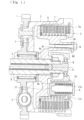
Fig. 1] Fig. 1 is an overall longitudinal sectional view of a power transmission device according to a first embodiment of the present invention. - [
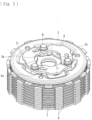
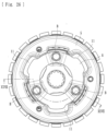
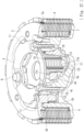
Fig. 2] Fig. 2 is a perspective view of the power transmission device in a state in which a clutch housing and the like are removed. - [
Fig. 3] Fig. 3 is a plan view of the power transmission device in a state in which the clutch housing and the like are removed. - [
Fig. 4] Fig. 4 is a cutaway view taken along line IV-IV inFig. 3 . - [[
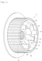
Fig. 5] Fig. 5 is a perspective view of a clutch member of the power transmission device. - [
Fig. 6] Fig. 6 is a plan view of the clutch member. - [
Fig. 7] Fig. 7 is a rear view of the clutch member. - [
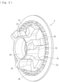
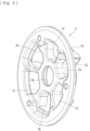
Fig. 8] Fig. 8 is a perspective view of a pressure member of the power transmission device as seen from one side. - [
Fig. 9] Fig. 9 is a perspective view of the pressure member as seen from the other side. - [
Fig. 10] Fig. 10 is a back view of the pressure member. - [
Fig. 11] Fig. 11 is a plan view of the pressure member. - [
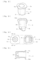
Fig. 12] Fig. 12 is a perspective view of a receiving member of the power transmission device as seen from one side. - [
Fig. 13] Fig. 13 is a perspective view of the receiving member as seen from the other side. - [
Fig. 14] Fig. 14 shows a plan view and a rear view of the receiving member. - [
Fig. 15] Fig. 15 is a sectional view taken along line XV-XV inFig. 14 . - [
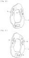
Fig. 16] Fig. 16 is a perspective view of a fixing member of the power transmission device as seen from one side. - [
Fig. 17] Fig. 17 is a perspective view of the fixing member as seen from the other side. - [
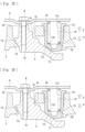
Fig. 18] Fig. 18 is a developed view illustrating cam surfaces of the power transmission device (when the vehicle is accelerating and the clutch is engaged). - [
Fig. 19] Fig. 19 is a developed view illustrating the cam surfaces of the power transmission device (when the vehicle is decelerating and the clutch is engaged). - [
Fig. 20] Fig. 20 is a developed view illustrating the cam surfaces of the power transmission device (when the vehicle is decelerating and the clutch is disengaged). - [
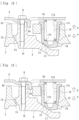
Fig. 21] Fig. 21 is a plan view of a power transmission device according to a second embodiment of the present invention in a state in which a clutch housing and the like are removed. - [
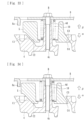
Fig. 22] Fig. 22 is a cutaway view taken along line XXII-XXII inFig. 21 . - [
Fig. 23] Fig. 23 is a developed view illustrating cam surfaces of the power transmission device (when the vehicle is accelerating and the clutch is engaged). - [
Fig. 24] Fig. 24 is a developed view illustrating the cam surfaces of the power transmission device (when the vehicle is decelerating and the clutch is engaged). - [
Fig. 25] Fig. 25 is a developed view illustrating the cam surfaces of the power transmission device (when the vehicle is decelerating and the clutch is disengaged). - [
Fig. 26] Fig. 26 is plan view of a power transmission device according to a third embodiment of the present invention in a state in which a clutch housing and the like are removed. - [
Fig. 27] Fig. 27 is a cutaway view taken along line XXVII-XXVII inFig. 26 . - [
Fig. 28] Fig. 28 is a developed view illustrating cam surfaces of the power transmission device (when the vehicle is accelerating and the clutch is engaged). - [
Fig. 29] Fig. 29 is a developed view illustrating the cam surfaces of the power transmission device (when the vehicle is decelerating and the clutch is engaged). - [
Fig. 30] Fig. 30 is a developed view illustrating the cam surfaces of the power transmission device (when the vehicle is decelerating and the clutch is disengaged). - [
Fig. 31] Fig. 31 is a plan view of a power transmission device according to a fourth embodiment of the present invention in a state in which a clutch housing and the like are removed. - [
Fig. 32] Fig. 32 is a cutaway view taken along line XXXII-XXXII inFig. 31 . - [
Fig. 33] Fig. 33 is a developed view illustrating cam surfaces of the power transmission device (when the vehicle is accelerating and the clutch is engaged). - [
Fig. 34] Fig. 34 is a developed view illustrating the cam surfaces of the power transmission device (when the vehicle is decelerating and the clutch is engaged). - [
Fig. 35] Fig. 35 is a developed view illustrating the cam surfaces of the power transmission device (when the vehicle is decelerating and the clutch is disengaged). - Hereafter, embodiments of the present invention will be described in detail with reference to the drawings.
- A power transmission device according to the present embodiment is disposed in a vehicle, such as a motorcycle, and appropriately transmits or cuts off driving power of an engine to the transmission and driving wheel side. As illustrated in
Fig. 1 , the power transmission device is mainly composed of: aclutch housing 2 on which agear 1 as an input member is formed, aclutch member 4 coupled to a shaft 3 as an output member, apressure member 5 formed on the right-end side of theclutch member 4 in the figure, drive-side clutch plates 6 coupled to theclutch housing 2 side, driven-side clutch plates 7 coupled to theclutch member 4 side, afixing member 8, apush rod 9,clutch springs 10 as urging means, and receivingmembers 11. In the figure, the symbol S represents a damper, and the symbol D represents a ball bearing. - The
gear 1 can rotate around the shaft 3 when driving power (rotational power) transmitted from the engine is input. Thegear 1 is coupled to theclutch housing 2 by using rivets and the like. Theclutch housing 2 is constituted by a cylindrical case member whose right end side in the figure is open. A plurality of drive-side clutch plates 6 are attached to the inner peripheral wall of theclutch housing 2. Each of the drive-side clutch plates 6 is constituted by a substantially annular plate, is fitted into a spline formed in the inner peripheral surface of theclutch housing 2, and thus is configured to be rotatable together with rotation of theclutch housing 2 and slidable in the axial direction (left-right directions inFig. 1 ). - The
clutch member 4 is constituted by members disposed in theclutch housing 2. As illustrated inFigs. 5 to 7 , theclutch member 4 includes acentral hole 4a through which the shaft 3 can be inserted, an outerperipheral wall 4b in which splines are formed,bolt holes 4c through which bolts B can be inserted, andboss portions 4d in which thebolt holes 4c are formed. Splines are formed in each of the inner peripheral surface of thecentral hole 4a and the outer peripheral surface of the shaft 3. The shaft 3 is spline-fitted and coupled to thecentral hole 4a, so that the shaft 3 also rotates when theclutch member 4 rotates. The driven-sideclutch plates 7 are fitted and attached to the splines formed in the outerperipheral wall 4b. - To be more specific, the splines, which are formed in the outer
peripheral wall 4b of theclutch member 4, are composed of protrusions and recesses that are integrally formed around substantially the entire periphery of the outerperipheral wall 4b. Because the driven-sideclutch plates 7 engage with recessed grooves of the splines, movement of the driven-sideclutch plates 7 in the rotational direction is restricted while movement of the driven-sideclutch plates 7 relative to theclutch member 4 in the axial direction is allowed, and the driven-sideclutch plates 7 can rotate together with theclutch member 4. - The driven-side
clutch plates 7 are formed so as to be stacked alternately with the drive-sideclutch plates 6. The drive-sideclutch plates 6 and the driven-sideclutch plates 7 that are adjacent to each other can be pressed against each other or the press-contact force can be released. That is, the drive-sideclutch plates 6 and the driven-sideclutch plates 7 are allowed to slide in the axial direction of theclutch member 4. When pressed by thepressure member 5 in the leftward direction inFig. 1 , the drive-sideclutch plates 6 and the driven-sideclutch plates 7 are pressed against each other, so that the rotational power of theclutch housing 2 can be transmitted to the shaft 3 via theclutch member 4. When pressing by thepressure member 5 is relieved, the press-contact force is released, theclutch member 4 stops following the rotation of theclutch housing 2 and stops, so that rotational power is not transmitted to the shaft 3. - Moreover, as illustrated in
Figs. 2 to 4 , the fixingmember 8 is fixed to the tip- end side of theboss portions 4d by using the bolts B, which are inserted through the bolt holes 4c. The clutch springs 10 as urging means are attached to the fixingmember 8. To be specific, the fixingmember 8 is constituted by an annular metal member, is fixed to the tip ends of theboss portions 4d by using the bolts B, and is mounted in such a way that the receivingmembers 11 are positioned between the bolts B and the other end portions of the clutch springs 10 are in contact therewith. - Each of the
clutch spring 10 is constituted by a coil spring that is mounted in such a way that, in a state of being contained in the receivingmember 11, one end thereof is in contact with the bottom surface side of the receiving member 11 (to be specific, a receivingportion 11b described below) and the other end thereof is in contact with the fixingmember 8. Theclutch spring 10 can constantly urge thepressure member 5 in a direction such that the drive-sideclutch plates 6 and the driven-sideclutch plates 7 are pressed against each other (that is, a direction such that thepressure member 5 becomes closer to the clutch member 4). Another urging means may be used as theclutch spring 10. - The
pressure member 5 is attached to theclutch member 4 at a position on the right end side inFig. 1 in such a way that thepressure member 5 is movable in the axial direction of the clutch member 4 (left-right directions inFig. 1 ). Thepressure member 5 can press the drive-sideclutch plates 6 and the driven-sideclutch plates 7 against each other or release the press-contact force in accordance with movement thereof relative to theclutch member 4 in the axial direction. To be more specific, as illustrated inFigs. 8 to 11 , thepressure member 5 includes aflange portion 5a that can press the drive-sideclutch plates 6 and the driven-sideclutch plates 7 against each other, attachment holes 5b for attaching the receivingmembers 11, through-holes 5c, and acentral hole 5d. - Among these, to the
central hole 5d of thepressure member 5, a pressed member E is attached via the ball bearing D as illustrated inFig. 1 . The pressed member E is attached to the tip end side of the shaft 3 and is movable so as to follow thepush rod 9. When a driver operates operation means, such as a clutch lever or the like (not shown), to cause thepush rod 9 to protrude in the rightward direction in the figure, the pressed member E moves in the same direction. Thus, thepressure member 5 can be moved in the rightward direction inFig. 1 (direction away from the clutch member 4) against the urging forces of the clutch springs 10. - When the
pressure member 5 moves in the rightward direction, the press-contact force between the drive-sideclutch plates 6 and the driven-sideclutch plates 7 is released, and rotational power input to thegear 1 and theclutch housing 2 is cut off and not transmitted to theclutch member 4 and the shaft 3 (clutch is disengaged). When the driver stops operating the operation means, thepressure member 5 moves in the leftward direction inFig. 1 due to the urging forces of the clutch springs 10, and the drive-sideclutch plates 6 and the driven-sideclutch plates 7 are pressed against each other. Thus, rotational power input to thegear 1 and theclutch housing 2 is transmitted to theclutch member 4 and the shaft 3 (clutch is engaged). - That is, the
pressure member 5 is configured to be capable of pressing the drive-sideclutch plates 6 and the driven-sideclutch plates 7 against each other or releasing the press-contact force in accordance with movement thereof relative to theclutch member 4 in the axial direction. Thepush rod 9 and the pressed member E, which are activated by an operation performed by a driver and which can release the press-contact force between the drive-sideclutch plates 6 and the driven-sideclutch plates 7 by moving thepressure member 5 against the urging force of the clutch spring 10 (urging means) as described above, constitute "activation means" of the present invention. - Moreover, the attachment holes 5b are formed in the
pressure member 5 at a plurality of (three) positions on the same circle at regular intervals, and the receivingmember 11 is attached to each of theattachment holes 5b. The receivingmember 11, which is attached to theattachment hole 5b of thepressure member 5, can make contact with one end of theclutch spring 10 and receive the urging force thereof, and is separate from thepressure member 5. To be specific, as illustrated inFigs. 12 to 15 , the receivingmember 11 according to the present embodiment is constituted by a cup-shaped member that includes: a recessedportion 11a that contains theclutch spring 10, the receivingportion 11b that is formed in the recessedportion 11a and that makes contact with one end portion of theclutch spring 10 and receives the urging force, and aflange portion 11c that makes contact with thepressure member 5 and that can transmit the urging force of theclutch spring 10 to thepressure member 5. - Among these, the
flange portion 11c is formed on the opening side of the receivingmember 11. When the receivingmember 11 is attached to theattachment hole 5b, theflange portion 11c makes contact with the opening edge of theattachment hole 5b. After attaching the receivingmember 11 to theattachment hole 5b, by mounting theclutch spring 10 into the recessedportion 11a in such a way that one end portion thereof is in contact with the receivingportion 11b, the urging force of theclutch spring 10 is transmitted to thepressure member 5 side via theflange portion 11c of the receivingmembers 11, and the drive-sideclutch plates 6 and the driven-sideclutch plates 7 can be pressed against each other by using the transmitted urging force. - Moreover, the power transmission device according to the present embodiment includes: a press-contact assisting cam that can increase the press-contact force between the drive-side
clutch plates 6 and the driven-sideclutch plates 7 if thepressure member 5 and theclutch member 4 rotate relative to each other when rotational power input to thegear 1 as an input member becomes capable of being transmitted to the shaft 3 as an output member; and a back-torque limiting cam that reduces the press-contact force between the drive-sideclutch plates 6 and the driven-sideclutch plates 7 if thepressure member 5 and theclutch member 4 rotate relative to each other when the rotation speed of the shaft 3 as an output member exceeds the rotation speed of thegear 1 as an input member. Cam surfaces (first to sixth cam surfacesC 1 to C6) that constitute the press-contact assisting cam and the back-torque limiting cam are shown by shading (cross-hatching) in the figures. - As illustrated in
Figs. 4 and18 , the press-contact assisting cam according to the present embodiment is configured by disposing the third cam surfaces C3 and the fourth cam surfaces C4, which are respectively formed in thepressure member 5 and theclutch member 4, so as to face each other. That is, when assembling theclutch member 4 and thepressure member 5 together, the third cam surfaces C3 (seeFig. 11 ) formed in thepressure member 5 and the fourth cam surfaces C4 (seeFig. 7 ) formed in theclutch member 4 are disposed so as to face each other. Thus, if thepressure member 5 and theclutch member 4 rotate relative to each other when rotational power input to thegear 1 becomes capable of being transmitted to the shaft 3, thepressure member 5 is moved in the direction α inFig. 18 by the cam function of the third cam surfaces C3 and the fourth cam surfaces C4 so that thepressure member 5 becomes closer to theclutch member 4, and thereby the press-contact force between the drive-sideclutch plates 6 and the driven-sideclutch plates 7 is increased. - As illustrated in
Figs. 4 and19 , the back-torque limiting cam according to the present embodiment is configured by disposing the first cam surfacesC 1 and the second cam surfaces C2, which are respectively formed in the receivingmembers 11 and theclutch member 4, so as to face each other. That is, when assembling theclutch member 4, thepressure member 5, and the receivingmembers 11 together, the first cam surfaces C1 (seeFigs. 13 and 14 ) formed in the bottom side surfaces of the receivingmembers 11 and the second cam surfaces C2 (seeFig. 6 ) formed in theclutch member 4 are disposed so as to face each other. Thus, if thepressure member 5 and theclutch member 4 rotate relative to each other when the rotation speed of the shaft 3 exceeds the rotation speed of thegear 1, the receivingmembers 11 are moved in the direction β inFig. 19 by the cam function of the first cam surfaces C1 and the second cam surfaces C2 so as to reduce the urging force of the clutch springs 10 transmitted to thepressure member 5, and thereby the press-contact force between the drive-sideclutch plates 6 and the driven-sideclutch plates 7 is reduced. Reduction of the press-contact force refers to a state in which rotational-power transmitting capacity is reduced due to sliding of the drive-sideclutch plates 6 and the driven-sideclutch plates 7 over each other. - Moreover, as illustrated in
Fig. 14 , in each of the receivingmembers 11 according to the present embodiment, the fifth cam surface C5 is formed on a side opposite from the first cam surface C1; and the sixth cam surfaces C6 (seeFig. 11 ), each of which faces the fifth cam surface C5, is formed in thepressure member 5. That is, in both side surfaces of the bottom portion of each of the receivingmembers 11, the first cam surface C1 and the fifth cam surface C5 are respectively formed; and the back-torque limiting cam is constituted by the first cam surfaces C1, the second cam surfaces C2, the fifth cam surfaces C5, and the sixth cam surfaces C6. - When assembling the
clutch member 4, thepressure member 5, and the receivingmembers 11 together, the first cam surfaces C1 formed in the receivingmembers 11 and the second cam surfaces C2 formed in theclutch member 4 are disposed so as to face each other, and the fifth cam surfaces C5 formed in the receivingmembers 11 and the sixth cam surfaces C6 formed in thepressure member 5 are disposed so as to face each other. Thus, if thepressure member 5 and theclutch member 4 rotate relative to each other when the rotation speed of the shaft 3 exceeds the rotation speed of thegear 1, the receivingmembers 11 are moved in the direction β inFig. 19 by the cam function of the first cam surfaces C1 and the second cam surfaces C2 and the cam function of the fifth cam surfaces C5 and the sixth cam surfaces C6, and thereby the press-contact force between the drive-sideclutch plates 6 and the driven-sideclutch plates 7 is reduced. - Thus, when the back-torque limiting cam functions, the receiving
members 11 receive both of the cam function of the first cam surfaces C1 and the second cam surfaces C2 and the cam function of the fifth cam surfaces C5 and the sixth cam surfaces C6. Although the back-torque limiting cam according to the present embodiment includes the fifth cam surfaces C5 and the sixth cam surfaces C6, in addition to the first cam surfaces C1 and the second cam surfaces C2, the back-torque limiting cam may have only the first cam surfaces C1 and the second cam surfaces C2. - Here, the power transmission device according to the present embodiment includes a
rotation restricting portion 8a that is capable of restricting rotation, relative to theclutch member 4, of thepressure member 5 that has moved due to activation of thepush rod 9 and the pressed member E (activation means) and is capable of maintaining the clearance t (seeFig. 20 ) between a pair of cam surfaces (the first cam surface C1 and the second cam surface C2) that constitute a back-torque limiting cam. To be specific, as illustrated inFigs. 16 and 17 , therotation restricting portion 8a according to the present embodiment is formed by bending a predetermined part of the fixingmember 8. - That is, when the
push rod 9 and the pressed member E (activation means) are activated, thepressure member 5 moves, and the press-contact force between the drive-sideclutch plates 6 and the driven-sideclutch plates 7 is released (the clutch is disengaged). Then, as illustrated inFig. 20 , thepressure member 5 interferes with therotation restricting portion 8a and movement of thepressure member 5 in the direction is restricted, and the clearance between t between the first cam surface C1 and the second cam surface C2, which constitute the back-torque limiting cam, is maintained. Thus, therotation restricting portion 8a is configured to be capable of preventing thepressure member 5 from rotating and the receivingmember 11 from becoming stuck onto the second cam surface C2 when the activation means (thepush rod 9 and the pressed member E) are activated. - The present embodiment includes the
rotation restricting portion 8a that is capable of restricting rotation, relative to theclutch member 4, (rotation in a direction such that the first cam surface C1 and the second cam surface C2 become closer to each other) of thepressure member 5 that has moved due to activation of activation means (thepush rod 9 and the pressed member E) and is capable of maintaining the clearance between the pair of cam surfaces (the first cam surface C1 and the second cam surface C2) that constitute the back-torque limiting cam. Therefore, with the present embodiment, by restricting rotation of thepressure member 5 when a driver disengages the clutch, it is possible to improve responsiveness when the driver subsequently engages the clutch and to improve operability. - Moreover, the present embodiment includes the receiving
member 11 that is constituted by a separate member attached to thepressure member 5, that receives an urging force of the clutch spring 10 (urging means) on thepressure member 5 side, and that is capable of transmitting the urging force to thepressure member 5; and the back-torque limiting cam has the first cam surface C1, which is one cam surface, formed in the receivingmember 11 and the second cam surface C2, which is the other cam surface, formed in theclutch member 4. Therefore, with the present embodiment, by restricting rotation of thepressure member 5 when a driver disengages the clutch, it is possible to prevent the receivingmember 11 from becoming stuck onto the second cam surface C2, which constitutes the back-torque limiting cam, and it is possible to improve responsiveness when the driver subsequently engages the clutch and to improve operability. - Moreover, the
rotation restricting portion 8a according to the present embodiment is formed in a predetermined part of the fixing member 8 (in particular, integrally formed by bending a predetermined part of the fixing member 8). Therefore, by performing replacement to the fixingmember 8 having therotation restricting portion 8a in an existing power transmission device, it is possible to restrict rotation of thepressure member 5 when a driver disengages the clutch, and it is possible to improve responsiveness when the driver subsequently engages the clutch and to improve operability. - Next, a power transmission device according to a second embodiment of the present invention will be described.
- As with the first embodiment, a power transmission device according to the present embodiment is disposed in a vehicle, such as a motorcycle, and appropriately transmits or cuts off driving power of an engine to the transmission and driving wheel side. The power transmission device is mainly composed of: a
clutch housing 2 on which agear 1 as an input member is formed, aclutch member 4 coupled to a shaft 3 as an output member, apressure member 5 formed on the right-end side of theclutch member 4 in the figure, drive-sideclutch plates 6 coupled to theclutch housing 2 side, driven-sideclutch plates 7 coupled to theclutch member 4 side, a fixingmember 8, apush rod 9, clutch springs 10 as urging means, and receivingmembers 11. Elements that are the same as those of the first embodiment will be denoted by the same numerals, and detailed descriptions of such elements will be omitted. - The press-contact assisting cam according to the present embodiment is configured as follows: when assembling the
clutch member 4 and thepressure member 5 together, the third cam surfaces C3 formed in thepressure member 5 and the fourth cam surfaces C4 formed in theclutch member 4 are disposed so as to face each other; thus, if thepressure member 5 and theclutch member 4 rotate relative to each other when rotational power input to thegear 1 becomes capable of being transmitted to the shaft 3, thepressure member 5 is moved in the direction α inFig. 23 by the cam function of the third cam surfaces C3 and the fourth cam surfaces C4 so that thepressure member 5 becomes closer to theclutch member 4; and thereby the press-contact force between the drive-sideclutch plates 6 and the driven-sideclutch plates 7 is increased. - The back-torque limiting cam according to the present embodiment is configured as follows: when assembling the
clutch member 4, thepressure member 5, and the receivingmembers 11 together, the first cam surfaces C1 formed in the bottom side surfaces of the receivingmembers 11 and the second cam surfaces C2 formed in theclutch member 4 are disposed so as to face each other; thus, if thepressure member 5 and theclutch member 4 rotate relative to each other when the rotation speed of the shaft 3 exceeds the rotation speed of thegear 1, the receivingmembers 11 are moved in the direction β inFig. 24 by the cam function of the first cam surfaces C1 and the second cam surfaces C2 so as to reduce the urging force of the clutch springs 10 transmitted to thepressure member 5; and thereby the press-contact force between the drive-sideclutch plates 6 and the driven-sideclutch plates 7 is reduced. - Here, as illustrated in
Figs. 21 and22 , arotation restricting portion 5e is integrally formed in a predetermined part of thepressure member 5 according to the present embodiment. Therotation restricting portion 5e is capable of restricting rotation, relative to theclutch member 4, of thepressure member 5 that has moved due to activation of thepush rod 9 and the pressed member E (activation means) and is capable of maintaining the clearance t (seeFig. 25 ) between a pair of cam surfaces (the first cam surface C1 and the second cam surface C2) that constitute the back-torque limiting cam. As illustrated inFig. 22 , therotation restricting portion 5e is formed by causing a predetermined part of thepressure member 5 to protrude in the rotation direction of thepressure member 5. - That is, when the
push rod 9 and the pressed member E (activation means) are activated, thepressure member 5 moves, and the press-contact force between the drive-sideclutch plates 6 and the driven-sideclutch plates 7 is released (the clutch is disengaged). Then, as illustrated inFig. 25 , therotation restricting portion 5e formed in thepressure member 5 interferes with theboss portion 4d of theclutch member 4 and movement of thepressure member 5 in the direction is restricted, and the clearance t between the first cam surface C1 and the second cam surface C2, which constitute the back-torque limiting cam, is maintained. Thus, therotation restricting portion 5e is configured to be capable of preventing thepressure member 5 from rotating and the receivingmember 11 from becoming stuck onto the second cam surface C2 when the activation means (thepush rod 9 and the pressed member E) are activated. A part that interferes with therotation restricting portion 5e is not limited to theboss portion 4d of theclutch member 4, and may be another part (including a separately and newly formed part). - The present embodiment includes the
rotation restricting portion 5e that is capable of restricting rotation, relative to theclutch member 4, (rotation in a direction such that the first cam surface C1 and the second cam surface C2 become closer to each other) of thepressure member 5 that has moved due to activation of activation means (thepush rod 9 and the pressed member E) and is capable of maintaining the clearance between the pair of cam surfaces (the first cam surface C1 and the second cam surface C2) that constitute the back-torque limiting cam. Therefore, with the present embodiment, by restricting rotation of thepressure member 5 when a driver disengages the clutch, it is possible to improve responsiveness when the driver subsequently engages the clutch and to improve operability. - Moreover, the present embodiment includes the receiving
member 11 that is constituted by a separate member attached to thepressure member 5, that receives an urging force of the clutch spring 10 (urging means) on thepressure member 5 side, and that is capable of transmitting the urging force to thepressure member 5; and the back-torque limiting cam has the first cam surface C1, which is one cam surface, formed in the receivingmember 11 and the second cam surface C2, which is the other cam surface, formed in theclutch member 4. Therefore, with the present embodiment, by restricting rotation of thepressure member 5 when a driver disengages the clutch, it is possible to prevent the receivingmember 11 from becoming stuck onto the second cam surface C2, which constitutes the back-torque limiting cam, and it is possible to improve responsiveness when the driver subsequently engages the clutch and to improve operability. - Furthermore, the
rotation restricting portion 5e according to the present embodiment is formed in a predetermined part of thepressure member 5, and therotation restricting portion 5e formed in thepressure member 5 that has moved due to activation of activation means (thepush rod 9 and the pressed member E) interferes with theboss portion 4d of theclutch member 4 and restricts rotation of thepressure member 5. Therefore, by partially changing the shape of thepressure member 5, it is possible to restrict rotation of thepressure member 5 when a driver disengages the clutch, and it is possible to improve responsiveness when the driver subsequently engages the clutch and to improve operability. - Next, a power transmission device according to a third embodiment of the present invention will be described.
- As with the first embodiment, a power transmission device according to the present embodiment is disposed in a vehicle, such as a motorcycle, and appropriately transmits or cuts off driving power of an engine to the transmission and driving wheel side. The power transmission device is mainly composed of: a
clutch housing 2 on which agear 1 as an input member is formed, aclutch member 4 coupled to a shaft 3 as an output member, apressure member 5 formed on the right-end side of theclutch member 4 in the figure, drive-sideclutch plates 6 coupled to theclutch housing 2 side, driven-sideclutch plates 7 coupled to theclutch member 4 side, a fixingmember 8, apush rod 9, clutch springs 10 as urging means, and receivingmembers 11. Elements that are the same as those of the first embodiment will be denoted by the same numerals, and detailed descriptions of such elements will be omitted. - The press-contact assisting cam according to the present embodiment is configured as follows: when assembling the
clutch member 4 and thepressure member 5 together, the third cam surfaces C3 formed in thepressure member 5 and the fourth cam surfaces C4 formed in theclutch member 4 are disposed so as to face each other; thus, if thepressure member 5 and theclutch member 4 rotate relative to each other when rotational power input to thegear 1 becomes capable of being transmitted to the shaft 3, thepressure member 5 is moved in the direction α inFig. 28 by the cam function of the third cam surfaces C3 and the fourth cam surfaces C4 so that thepressure member 5 becomes closer to theclutch member 4; and thereby the press-contact force between the drive-sideclutch plates 6 and the driven-sideclutch plates 7 is increased. - The back-torque limiting cam according to the present embodiment is configured as follows: when assembling the
clutch member 4, thepressure member 5, and the receivingmembers 11 together, the first cam surfaces C1 formed in the bottom side surfaces of the receivingmembers 11 and the second cam surfaces C2 formed in theclutch member 4 are disposed so as to face each other; thus, if thepressure member 5 and theclutch member 4 rotate relative to each other when the rotation speed of the shaft 3 exceeds the rotation speed of thegear 1, the receivingmembers 11 are moved in the direction β inFig. 29 by the cam function of the first cam surfaces C1 and the second cam surfaces C2 so as to reduce the urging force of the clutch springs 10 transmitted to thepressure member 5; and thereby the press-contact force between the drive-sideclutch plates 6 and the driven-sideclutch plates 7 is reduced. - Here, as illustrated in
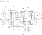
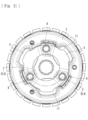
Figs. 26 and27 , arotation restricting portion 4e is integrally formed in a predetermined part of theclutch member 4 according to the present embodiment. Therotation restricting portion 4e is capable of restricting rotation, relative to theclutch member 4, of thepressure member 5 that has moved due to activation of thepush rod 9 and the pressed member E (activation means) and is capable of maintaining the clearance t (seeFig. 30 ) between a pair of cam surfaces (the first cam surface C1 and the second cam surface C2) that constitute the back-torque limiting cam. As illustrated inFig. 27 , therotation restricting portion 4e is formed by causing a predetermined part of the clutch member 4 (a predetermined part of theboss portion 4d in the present embodiment) to protrude in the rotation direction of thepressure member 5. - That is, when the
push rod 9 and the pressed member E (activation means) are activated, thepressure member 5 moves, and the press-contact force between the drive-sideclutch plates 6 and the driven-sideclutch plates 7 is released (the clutch is disengaged). Then, as illustrated inFig. 30 , thepressure member 5 interferes with therotation restricting portion 4e formed in theclutch member 4 and movement of thepressure member 5 in the direction is restricted, and the clearance t between the first cam surface C1 and the second cam surface C2, which constitute the back-torque limiting cam, is maintained. Thus, therotation restricting portion 4e is configured to be capable of preventing thepressure member 5 from rotating and the receivingmember 11 from becoming stuck onto the second cam surface C2 when the activation means (thepush rod 9 and the pressed member E) are activated. A part that interferes with therotation restricting portion 4e may be a separate and newly formed part of thepressure member 5. - The present embodiment includes the
rotation restricting portion 4e that is capable of restricting rotation, relative to theclutch member 4, (rotation in a direction such that the first cam surface C1 and the second cam surface C2 become closer to each other) of thepressure member 5 that has moved due to activation of activation means (thepush rod 9 and the pressed member E) and is capable of maintaining the clearance between the pair of cam surfaces (the first cam surface C1 and the second cam surface C2) that constitute the back-torque limiting cam. Therefore, with the present embodiment, by restricting rotation of thepressure member 5 when a driver disengages the clutch, it is possible to improve responsiveness when the driver subsequently engages the clutch and to improve operability. - Moreover, the present embodiment includes the receiving
member 11 that is constituted by a separate member attached to thepressure member 5, that receives an urging force of the clutch spring 10 (urging means) on thepressure member 5 side, and that is capable of transmitting the urging force to thepressure member 5; and the back-torque limiting cam has the first cam surface C1, which is one cam surface, formed in the receivingmember 11 and the second cam surface C2, which is the other cam surface, formed in theclutch member 4. Therefore, with the present embodiment, by restricting rotation of thepressure member 5 when a driver disengages the clutch, it is possible to prevent the receivingmember 11 from becoming stuck onto the second cam surface C2, which constitutes the back-torque limiting cam, and it is possible to improve responsiveness when the driver subsequently engages the clutch and to improve operability. - Furthermore, the
rotation restricting portion 4e according to the present embodiment is formed in a predetermined part of theclutch member 4, and thepressure member 5 that has moved due to activation of activation means (thepush rod 9 and the pressed member E) interferes with therotation restricting portion 4e formed in theclutch member 4 and restricts rotation of thepressure member 5. Therefore, by partially changing the shape of theclutch member 4, it is possible to restrict rotation of thepressure member 5 when a driver disengages the clutch, and it is possible to improve responsiveness when the driver subsequently engages the clutch and to improve operability. - Next, a power transmission device according to a fourth embodiment of the present invention will be described.
- As with the first embodiment, a power transmission device according to the present embodiment is disposed in a vehicle, such as a motorcycle, and appropriately transmits or cuts off driving power of an engine to the transmission and driving wheel side. The power transmission device is mainly composed of: a
clutch housing 2 on which agear 1 as an input member is formed, aclutch member 4 coupled to a shaft 3 as an output member, apressure member 5 formed on the right-end side of theclutch member 4 in the figure, drive-sideclutch plates 6 coupled to theclutch housing 2 side, driven-sideclutch plates 7 coupled to theclutch member 4 side, a fixingmember 8, apush rod 9, andclutch springs 10 as urging means. Elements that are the same as those of the first embodiment will be denoted by the same numerals, and detailed descriptions of such elements will be omitted. However, the power transmission device according to the present embodiment does not have the receivingmembers 11 included in the first to third embodiments. - The press-contact assisting cam according to the present embodiment is configured as follows: when assembling the
clutch member 4 and thepressure member 5 together, the third cam surfaces C3 formed in thepressure member 5 and the fourth cam surfaces C4 formed in theclutch member 4 are disposed so as to face each other; thus, if thepressure member 5 and theclutch member 4 rotate relative to each other when rotational power input to thegear 1 becomes capable of being transmitted to the shaft 3, thepressure member 5 is moved in the direction α inFig. 33 by the cam function of the third cam surfaces C3 and the fourth cam surfaces C4 so that thepressure member 5 becomes closer to theclutch member 4; and thereby the press-contact force between the drive-sideclutch plates 6 and the driven-sideclutch plates 7 is increased. - The back-torque limiting cam according to the present embodiment is configured as follows: when assembling the
clutch member 4 and thepressure member 5 together, the first cam surfaces C1 formed in thepressure member 5 and the second cam surfaces C2 formed in theclutch member 4 are disposed so as to face each other; thus, if thepressure member 5 and theclutch member 4 rotate relative to each other when the rotation speed of the shaft 3 exceeds the rotation speed of thegear 1, thepressure member 5 is moved in the direction β inFig. 34 by the cam function of the first cam surfacesC 1 and the second cam surfaces C2; and thereby the press-contact force between the drive-sideclutch plates 6 and the driven-sideclutch plates 7 is reduced. - Here, as illustrated in
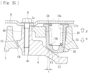
Figs. 16 and 17 , arotation restricting portion 8a is integrally formed in a predetermined part of the fixingmember 8 according to the present embodiment. Therotation restricting portion 8a is capable of restricting rotation, relative to theclutch member 4, of thepressure member 5 that has moved due to activation of thepush rod 9 and the pressed member E (activation means) and is capable of maintaining the clearance t (seeFig. 35 ) between a pair of cam surfaces (the first cam surface C1 and the second cam surface C2) that constitute the back-torque limiting cam. As illustrated inFig. 32 , therotation restricting portion 8a is formed by bending a predetermined part of the fixingmember 8. - That is, when the
push rod 9 and the pressed member E (activation means) are activated, thepressure member 5 moves, and the press-contact force between the drive-sideclutch plates 6 and the driven-sideclutch plates 7 is released (the clutch is disengaged). Then, as illustrated inFig. 35 , thepressure member 5 interferes with therotation restricting portion 8a and movement of thepressure member 5 in the direction is restricted, and the clearance t between the first cam surface C1 and the second cam surface C2, which constitute the back-torque limiting cam, is maintained. Thus, therotation restricting portion 8a is configured to be capable of preventing thepressure member 5 from rotating and the first cam surface C1 from becoming stuck onto the second cam surface C2 when the activation means (thepush rod 9 and the pressed member E) are activated. - The present embodiment includes the
rotation restricting portion 8a that is capable of restricting rotation, relative to theclutch member 4, (rotation in a direction such that the first cam surface C1 and the second cam surface C2 become closer to each other) of thepressure member 5 that has moved due to activation of activation means (thepush rod 9 and the pressed member E) and is capable of maintaining the clearance between the pair of cam surfaces (the first cam surface C1 and the second cam surface C2) that constitute the back-torque limiting cam. Therefore, with the present embodiment, by restricting rotation of thepressure member 5 when a driver disengages the clutch, it is possible to improve responsiveness when the driver subsequently engages the clutch and to improve operability. - Moreover, the
rotation restricting portion 8a according to the present embodiment is formed in a predetermined part of the fixing member 8 (in particular, integrally formed by bending a predetermined part of the fixing member 8). Therefore, by performing replacement to the fixingmember 8 having therotation restricting portion 8a in an existing power transmission device, it is possible to restrict rotation of thepressure member 5 when a driver disengages the clutch, and it is possible to improve responsiveness when the driver subsequently engages the clutch and to improve operability. - The present invention is not limited to the embodiments described above. For example, the present invention may be applied to a power transmission device that does not have the press-contact assisting cam (the third cam surface C3 and the fourth cam surface C4). Even in this case, the power transmission device includes the rotation restricting portion (8a, 4e, 5e) that is capable of restricting rotation, relative to the clutch member 4 (rotation in a direction such that the first cam surface C1 and the second cam surface C2 become closer to each other) of the
pressure member 5 that has moved due to activation of activation means (thepush rod 9 and the pressed member E) and is capable of maintaining the clearance between the pair of cam surfaces (the first cam surface C1 and the second cam surface C2) that constitute the back-torque limiting cam. Thus, by restricting rotation of thepressure member 5 when a driver disengages the clutch, it is possible to improve responsiveness when the driver subsequently engages the clutch and to improve operability. - The number of receiving
members 11 attached and the shape of each of the receivingmembers 11 are not limited. The present invention is applicable to a power transmission device that does not have a receivingmember 11 as in the fourth embodiment. The power transmission device according to the present invention can be used as a multiple disc clutch for a motorcycle, an automobile, a three-wheeled or four-wheeled ATV, a general-purpose machine, or the like. - The present disclosure also explicitly concerns the following aspects, each of which may also be applied to the present invention. That is, the following aspects can be claimed as such or combined with the appended claims.
- (I) A power transmission device comprising:
- a clutch housing that rotates together with rotation of an input member and to which
- a plurality of drive-side clutch plates are attached;
- a clutch member to which a plurality of driven-side clutch plates that are formed alternately with the drive-side clutch plates of the clutch housing are attached and to which an output member is coupled;
- a pressure member that is attached to the clutch member and that is capable of pressing the drive-side clutch plates and the driven-side clutch plates against each other or releasing a press-contact force in accordance with movement thereof relative to the clutch member in an axial direction;
- urging means that urges the pressure member in a direction such that the drive-side clutch plates and the driven-side clutch plates are pressed against each other;
- a back-torque limiting cam that is constituted by a first cam surface and a second cam surface that reduces the press-contact force between the drive-side clutch plates and the driven-side clutch plates by rotating the pressure member and the clutch member relative to each other when a rotation speed of the output member exceeds a rotation speed of the input member; and
- a third cam surface and a fourth cam surface that increases the press-contact force between the drive-side clutch plates and the driven-side clutch plates by bringing the pressure member closer to the clutch member,
- wherein the power transmission device is capable of transmitting or cutting off rotational power that is input to the input member to the output member by pressing the drive-side clutch plates and the driven-side clutch plates against each other or releasing the press-contact force,
- the power transmission device including a rotation restricting portion that is capable of restricting rotation, relative to the clutch member, of the pressure member when the back-torque limiting cam is activated and the pressure member rotates relative to the clutch
- member and, in a circumferentially expanded view, is provided between the back-torque limiting cam and the third and fourth cam surfaces.
- (II) The clutch member of the power transmission device of (I) has a boss portion that fixes a fixing member to which the urging means contacts, and the rotation restricting portion is formed in a predetermined portion of the boss portion.
- (III) The rotation restricting portion of the power transmission of (I) is formed in a predetermined portion of the pressure member.
- (IV) The power transmission device described (I) comprises a fixing member that is fixed to the clutch member and to which the urging means contacts, wherein the rotation restricting portion is formed in a predetermined part of the fixing member.
- (V) The rotation restricting portion of the power transmission of (I) is configured to maintain the clearance between the first cam surface and the second cam surface.
- (VI) The rotation restricting portion of the power transmission of (I) comprises an activation means that is capable of releasing the press-contact force between the drive-side clutch plates and the driven-side clutch plates by moving the pressure member against an urging force of the urging means, wherein the rotation restricting portion is capable of restricting rotation, relative to the clutch member, of the pressure member that has moved due to activation of the activation means.
- (VII) The rotation restricting portion of the power transmission of (I) comprises an activation means that is activated by an operation performed by a driver and that is capable of releasing the press-contact force between the drive-side clutch plates and the driven-side clutch plates by moving the pressure member against an urging force of the urging means, wherein the rotation restricting portion is capable of restricting rotation, relative to the clutch member, of the pressure member that has moved due to activation of the activation means.
- (VIII) A power transmission device comprising:
- a clutch housing that rotates together with rotation of an input member and to which a plurality of drive-side clutch plates are attached;
- a clutch member to which a plurality of driven-side clutch plates that are formed alternately with the drive-side clutch plates of the clutch housing are attached and to which an output member is coupled;
- a pressure member that is attached to the clutch member and that is capable of pressing the drive-side clutch plates and the driven-side clutch plates against each other or releasing a press-contact force in accordance with movement thereof relative to the clutch member in an axial direction;
- urging means that urges the pressure member in a direction such that the drive-side clutch plates and the driven-side clutch plates are pressed against each other;
- activation means that is activated by an operation performed by a driver and that is capable of releasing a press-contact force between the drive-side clutch plates and the driven-side clutch plates by moving the pressure member against an urging force of the urging means; and
- a back-torque limiting cam that is constituted by a pair of cam surfaces that reduce the press-contact force between the drive-side clutch plates and the driven-side clutch plates if the pressure member and the clutch member rotate relative to each other when a rotation speed of the output member exceeds a rotation speed of the input member,
- wherein the power transmission device is capable of transmitting or cutting off rotational power that is input to the input member to the output member by pressing the drive-side clutch plates and the driven-side clutch plates against each other or releasing the press-contact force, and
- wherein the power transmission device includes a rotation restricting portion that is capable of restricting rotation, relative to the clutch member, of the pressure member that has moved due to activation of the activation means and is capable of maintaining a clearance between the pair of cam surfaces that constitute the back-torque limiting cam.
- (IX) The power transmission device according to VIII, comprising a receiving member that is constituted by a separate member attached to the pressure member, that receives an urging force of the urging means on the pressure member side, and that is capable of transmitting the urging force to the pressure member, wherein one of the cam surfaces of the back-torque limiting cam is formed in the receiving member, and the other cam surface of the back-torque limiting cam is formed in the clutch member.
- (X) The power transmission device according to VIII or IX, comprising a fixing member that is fixed to the clutch member and to which the urging means is attached, wherein the rotation restricting portion is formed in a predetermined part of the fixing member.
- (XI) The power transmission device according to VIII or IX, wherein the rotation restricting portion is formed in a predetermined part of the pressure member, and the rotation restricting portion formed in the pressure member that has moved due to activation of the activation means interferes with the clutch member and restricts rotation of the pressure member.
- (XII) The power transmission device according to (XII), wherein the rotation restricting portion is formed in a predetermined part of the clutch member, and the pressure member that has moved due to activation of the activation means interferes with the rotation restricting portion formed in the clutch member and restricts rotation of the pressure member.
- In any of the above aspects, if the driver tries to reengage the clutch (press the clutch plates against each other again) in such a state, it may be difficult for the receiving member to return to the original position due to the edge effect between the one cam surface and the other cam surface. Thus, a problem arises in that response when engaging the clutch becomes slow and the driver experiences an unpleasant sensation in operability due to feeling of idle running. Such a problem arises not only in a device that includes the receiving member separately from the pressure member but also in a device in which one cam surface is integrally formed in the pressure member.
- The present invention is applicable to any power transmission device that has a different outer shape or that has additional functions.
-
- 1
- gear (input member)
- 2
- clutch housing
- 3
- shaft (output member)
- 4
- clutch member
- 4a
- central hole
- 4b
- outer peripheral wall
- 4c
- bolt hole
- 4d
- boss portion
- 4e
- rotation restricting portion
- 5
- pressure member
- 5a
- flange portion
- 5b
- attachment hole
- 5c
- through-hole
- 5d
- central hole
- 5e
- rotation restricting portion
- 6
- drive-side clutch plate
- 7
- driven-side clutch plate
- 8
- fixing member
- 8a
- rotation restricting portion
- 9
- push rod (activation means)
- 10
- clutch spring (urging means)
- 11
- receiving member
- 11a
- recessed portion
- 11b
- receiving portion
- 11c
- flange portion
- C1
- first cam surface
- C2
- second cam surface
- C3
- third cam surface
- C4
- fourth cam surface
- C5
- fifth cam surface
- C6
- sixth cam surface
Claims (2)
- A power transmission device comprising:a clutch housing (2) that rotates together with rotation of an input member and to which a plurality of drive-side clutch plates (6) are attached;a clutch member (4) to which a plurality of driven-side clutch plates (7) that are formed alternately with the drive-side clutch plates (6) of the clutch housing (2) are attached and to which an output member is coupled;a pressure member (5) that is attached to the clutch member (4) and that is capable of pressing the drive-side clutch plates (6) and the driven-side clutch plates (7) against each other or releasing a press-contact force in accordance with movement thereof relative to the clutch member (4) in an axial direction;urging means (10) that urges the pressure member (5) in a first direction such that the drive-side clutch plates (6) and the driven-side clutch plates (7) are pressed against each other;fixing member (8) that is fixed to the clutch member (4) and to which the urging means (10) is attached;a press-contact assisting cam that is constituted by a pair of cam surfaces that increase the press-contact force between the drive-side clutch plates (6) and the driven-side clutch plates (7) if the pressure member (5) and the clutch member (4) rotate relative to each other in a state a rotational power input to the input member becomes capable of being transmitted to the output member,a back-torque limiting cam that is constituted by a pair of cam surfaces that reduce the press-contact force between the drive-side clutch plates (6) and the driven-side clutch plates (7) if the pressure member (5) and the clutch member (4) rotate relative to each other when a rotation speed of the output member exceeds a rotation speed of the input member,wherein the power transmission device is capable of transmitting or cutting off rotational power that is input to the input member to the output member by pressing the drive-side clutch plates (6) and the driven-side clutch plates (7) against each other or releasing the press-contact force, andthe clutch member (4) includesa clutch member assisting cam surface (C4) that is one of the pair of cam surfaces of the press-contact assisting cam and a clutch member limiting cam surface (C2) that is one of the pair of cam surfaces of the back-torque limiting cam, anda boss portion (4d) to a tip end of which in a second direction the fixing member (8) is fixed, the second direction being opposite to the first direction.
- The power transmission device according to claim 1, wherein the clutch member assisting cam surface (C4) and the clutch member limiting cam surface (C2) are formed in the clutch member at a side along the first direction from the tip end.
Applications Claiming Priority (4)
| Application Number | Priority Date | Filing Date | Title |
|---|---|---|---|
| JP2018002703A JP7217588B2 (en) | 2018-01-11 | 2018-01-11 | power transmission device |
| EP23214354.5A EP4310355A3 (en) | 2018-01-11 | 2019-01-09 | Power transmission device |
| PCT/JP2019/000382 WO2019139045A1 (en) | 2018-01-11 | 2019-01-09 | Power transmission device |
| EP19738506.5A EP3739231B1 (en) | 2018-01-11 | 2019-01-09 | Power transmission device |
Related Parent Applications (2)
| Application Number | Title | Priority Date | Filing Date |
|---|---|---|---|
| EP19738506.5A Division EP3739231B1 (en) | 2018-01-11 | 2019-01-09 | Power transmission device |
| EP23214354.5A Division EP4310355A3 (en) | 2018-01-11 | 2019-01-09 | Power transmission device |
Publications (2)
| Publication Number | Publication Date |
|---|---|
| EP4528123A2 true EP4528123A2 (en) | 2025-03-26 |
| EP4528123A3 EP4528123A3 (en) | 2025-06-04 |
Family
ID=67219493
Family Applications (3)
| Application Number | Title | Priority Date | Filing Date |
|---|---|---|---|
| EP23214354.5A Pending EP4310355A3 (en) | 2018-01-11 | 2019-01-09 | Power transmission device |
| EP25155601.5A Pending EP4528123A3 (en) | 2018-01-11 | 2019-01-09 | Power transmission device |
| EP19738506.5A Active EP3739231B1 (en) | 2018-01-11 | 2019-01-09 | Power transmission device |
Family Applications Before (1)
| Application Number | Title | Priority Date | Filing Date |
|---|---|---|---|
| EP23214354.5A Pending EP4310355A3 (en) | 2018-01-11 | 2019-01-09 | Power transmission device |
Family Applications After (1)
| Application Number | Title | Priority Date | Filing Date |
|---|---|---|---|
| EP19738506.5A Active EP3739231B1 (en) | 2018-01-11 | 2019-01-09 | Power transmission device |
Country Status (6)
| Country | Link |
|---|---|
| US (1) | US11149799B2 (en) |
| EP (3) | EP4310355A3 (en) |
| JP (1) | JP7217588B2 (en) |
| CN (1) | CN111615595B (en) |
| TW (1) | TWI790322B (en) |
| WO (1) | WO2019139045A1 (en) |
Families Citing this family (4)
| Publication number | Priority date | Publication date | Assignee | Title |
|---|---|---|---|---|
| JP6894792B2 (en) * | 2017-07-27 | 2021-06-30 | 株式会社エフ・シー・シー | Power transmission device |
| JP6903020B2 (en) * | 2018-01-11 | 2021-07-14 | 株式会社エフ・シー・シー | Power transmission device |
| JP7466632B2 (en) * | 2020-04-13 | 2024-04-12 | 株式会社エフ・シー・シー | Power transmission |
| JP7581288B2 (en) * | 2022-07-21 | 2024-11-12 | 株式会社エフ・シー・シー | Clutch device |
Citations (1)
| Publication number | Priority date | Publication date | Assignee | Title |
|---|---|---|---|---|
| WO2016024557A1 (en) | 2014-08-12 | 2016-02-18 | 株式会社エフ・シ-・シ- | Power transmission device |
Family Cites Families (22)
| Publication number | Priority date | Publication date | Assignee | Title |
|---|---|---|---|---|
| JP3378097B2 (en) * | 1994-09-29 | 2003-02-17 | 本田技研工業株式会社 | Friction clutch |
| JP3378100B2 (en) * | 1994-10-28 | 2003-02-17 | 本田技研工業株式会社 | Clutch structure |
| JP4252026B2 (en) * | 2004-11-09 | 2009-04-08 | 株式会社エフ・シー・シー | Manufacturing method of power transmission device |
| JP4364170B2 (en) * | 2005-07-14 | 2009-11-11 | 株式会社エフ・シー・シー | Power transmission device |
| JP2011021719A (en) * | 2009-07-17 | 2011-02-03 | Exedy Corp | Clutch device for motorcycle |
| JP5502507B2 (en) * | 2010-01-27 | 2014-05-28 | 株式会社エフ・シー・シー | Power transmission device |
| JP5995439B2 (en) * | 2011-12-28 | 2016-09-21 | 株式会社エフ・シー・シー | Power transmission device |
| JP5272089B1 (en) * | 2012-03-09 | 2013-08-28 | 株式会社エクセディ | Motorcycle clutch device |
| JP5854900B2 (en) * | 2012-03-16 | 2016-02-09 | 株式会社エフ・シー・シー | Power transmission device |
| JP5998571B2 (en) * | 2012-03-28 | 2016-09-28 | 株式会社ジェイテクト | Driving force transmission device and four-wheel drive vehicle equipped with the same |
| FR2990899B1 (en) * | 2012-05-24 | 2015-07-24 | Poclain Hydraulics Ind | HYDRAULIC APPARATUS COMPRISING AN IMPROVED ASSEMBLY OF A HYDRAULIC MACHINE AND A CLUTCH. |
| CN202746439U (en) * | 2012-09-14 | 2013-02-20 | 李德军 | Star-type friction clutch |
| US20140158489A1 (en) * | 2012-12-06 | 2014-06-12 | Tai-Her Yang | Clutch actuated by inertia mass and friction damping |
| DE102013000975A1 (en) * | 2013-01-22 | 2014-07-24 | Licos Trucktec Gmbh | "Friction clutch" |
| CN105229326B (en) * | 2013-03-15 | 2017-12-26 | 舍弗勒技术股份两合公司 | Clutch device |
| JP5626936B1 (en) * | 2013-06-03 | 2014-11-19 | ヤマハ発動機株式会社 | Clutch and saddle riding type vehicle having the same |
| JP6295690B2 (en) * | 2014-02-04 | 2018-03-20 | スズキ株式会社 | Clutch with back torque limiter |
| JP6104959B2 (en) * | 2015-02-09 | 2017-03-29 | 本田技研工業株式会社 | Clutch device |
| JP6501354B2 (en) * | 2015-05-12 | 2019-04-17 | 株式会社エフ・シー・シー | Power transmission system for vehicles |
| JP6801956B2 (en) * | 2015-12-04 | 2020-12-16 | 株式会社エクセディ | Motorcycle clutch device |
| US10161426B2 (en) * | 2016-03-25 | 2018-12-25 | Ford Global Technologies, Llc | Transmission and transmission clutch system |
| JP6710709B2 (en) * | 2018-01-10 | 2020-06-17 | 本田技研工業株式会社 | Multi-plate friction clutch |
-
2018
- 2018-01-11 JP JP2018002703A patent/JP7217588B2/en active Active
- 2018-12-05 TW TW107143667A patent/TWI790322B/en active
-
2019
- 2019-01-09 CN CN201980007774.8A patent/CN111615595B/en active Active
- 2019-01-09 EP EP23214354.5A patent/EP4310355A3/en active Pending
- 2019-01-09 WO PCT/JP2019/000382 patent/WO2019139045A1/en not_active Ceased
- 2019-01-09 EP EP25155601.5A patent/EP4528123A3/en active Pending
- 2019-01-09 EP EP19738506.5A patent/EP3739231B1/en active Active
-
2020
- 2020-07-10 US US16/925,794 patent/US11149799B2/en active Active
Patent Citations (1)
| Publication number | Priority date | Publication date | Assignee | Title |
|---|---|---|---|---|
| WO2016024557A1 (en) | 2014-08-12 | 2016-02-18 | 株式会社エフ・シ-・シ- | Power transmission device |
Also Published As
| Publication number | Publication date |
|---|---|
| WO2019139045A1 (en) | 2019-07-18 |
| EP3739231B1 (en) | 2023-12-06 |
| CN111615595A (en) | 2020-09-01 |
| TWI790322B (en) | 2023-01-21 |
| CN111615595B (en) | 2022-07-26 |
| EP4310355A2 (en) | 2024-01-24 |
| EP3739231A1 (en) | 2020-11-18 |
| JP2019120393A (en) | 2019-07-22 |
| EP4528123A3 (en) | 2025-06-04 |
| EP4310355A3 (en) | 2024-04-10 |
| EP3739231A4 (en) | 2021-09-29 |
| TW201937076A (en) | 2019-09-16 |
| US20200340537A1 (en) | 2020-10-29 |
| US11149799B2 (en) | 2021-10-19 |
| JP7217588B2 (en) | 2023-02-03 |
Similar Documents
| Publication | Publication Date | Title |
|---|---|---|
| JP5502507B2 (en) | Power transmission device | |
| EP3181933B1 (en) | Power transmission device | |
| EP2778457B1 (en) | Power transmission device | |
| JP4452301B2 (en) | Power transmission device | |
| EP3739232B1 (en) | Power transmission device | |
| US11149799B2 (en) | Power transmission device | |
| JP6603143B2 (en) | Power transmission device | |
| JP6502443B2 (en) | Power transmission | |
| EP4234968B1 (en) | Power transmission device | |
| JP2019044869A (en) | Power transmission | |
| JP2009063023A (en) | Power transmission device | |
| CN115628269B (en) | Power transmission device | |
| JP2009068577A (en) | Power transmission device | |
| JP4975723B2 (en) | Motorcycle clutch device | |
| JP4669359B2 (en) | Power transmission device | |
| JP2007205387A (en) | Power transmission device | |
| JP5324345B2 (en) | Power transmission device |
Legal Events
| Date | Code | Title | Description |
|---|---|---|---|
| PUAI | Public reference made under article 153(3) epc to a published international application that has entered the european phase |
Free format text: ORIGINAL CODE: 0009012 |
|
| STAA | Information on the status of an ep patent application or granted ep patent |
Free format text: STATUS: THE APPLICATION HAS BEEN PUBLISHED |
|
| AC | Divisional application: reference to earlier application |
Ref document number: 3739231 Country of ref document: EP Kind code of ref document: P Ref document number: 4310355 Country of ref document: EP Kind code of ref document: P |
|
| AK | Designated contracting states |
Kind code of ref document: A2 Designated state(s): AL AT BE BG CH CY CZ DE DK EE ES FI FR GB GR HR HU IE IS IT LI LT LU LV MC MK MT NL NO PL PT RO RS SE SI SK SM TR |
|
| REG | Reference to a national code |
Ref country code: DE Ref legal event code: R079 Free format text: PREVIOUS MAIN CLASS: F16D0013560000 Ipc: F16D0023120000 |
|
| PUAL | Search report despatched |
Free format text: ORIGINAL CODE: 0009013 |
|
| AK | Designated contracting states |
Kind code of ref document: A3 Designated state(s): AL AT BE BG CH CY CZ DE DK EE ES FI FR GB GR HR HU IE IS IT LI LT LU LV MC MK MT NL NO PL PT RO RS SE SI SK SM TR |
|
| RIC1 | Information provided on ipc code assigned before grant |
Ipc: F16D 13/56 20060101ALI20250430BHEP Ipc: F16D 23/12 20060101AFI20250430BHEP |
|
| STAA | Information on the status of an ep patent application or granted ep patent |
Free format text: STATUS: REQUEST FOR EXAMINATION WAS MADE |
|
| 17P | Request for examination filed |
Effective date: 20251203 |