EP4527983A1 - Water electrolysis arrangement - Google Patents
Water electrolysis arrangement Download PDFInfo
- Publication number
- EP4527983A1 EP4527983A1 EP23198228.1A EP23198228A EP4527983A1 EP 4527983 A1 EP4527983 A1 EP 4527983A1 EP 23198228 A EP23198228 A EP 23198228A EP 4527983 A1 EP4527983 A1 EP 4527983A1
- Authority
- EP
- European Patent Office
- Prior art keywords
- water
- aeration
- electrolyser
- raw
- stage
- Prior art date
- Legal status (The legal status is an assumption and is not a legal conclusion. Google has not performed a legal analysis and makes no representation as to the accuracy of the status listed.)
- Withdrawn
Links
Images


Classifications
-
- C—CHEMISTRY; METALLURGY
- C25—ELECTROLYTIC OR ELECTROPHORETIC PROCESSES; APPARATUS THEREFOR
- C25B—ELECTROLYTIC OR ELECTROPHORETIC PROCESSES FOR THE PRODUCTION OF COMPOUNDS OR NON-METALS; APPARATUS THEREFOR
- C25B1/00—Electrolytic production of inorganic compounds or non-metals
- C25B1/01—Products
- C25B1/02—Hydrogen or oxygen
- C25B1/04—Hydrogen or oxygen by electrolysis of water
-
- C—CHEMISTRY; METALLURGY
- C25—ELECTROLYTIC OR ELECTROPHORETIC PROCESSES; APPARATUS THEREFOR
- C25B—ELECTROLYTIC OR ELECTROPHORETIC PROCESSES FOR THE PRODUCTION OF COMPOUNDS OR NON-METALS; APPARATUS THEREFOR
- C25B15/00—Operating or servicing cells
- C25B15/08—Supplying or removing reactants or electrolytes; Regeneration of electrolytes
-
- C—CHEMISTRY; METALLURGY
- C25—ELECTROLYTIC OR ELECTROPHORETIC PROCESSES; APPARATUS THEREFOR
- C25B—ELECTROLYTIC OR ELECTROPHORETIC PROCESSES FOR THE PRODUCTION OF COMPOUNDS OR NON-METALS; APPARATUS THEREFOR
- C25B9/00—Cells or assemblies of cells; Constructional parts of cells; Assemblies of constructional parts, e.g. electrode-diaphragm assemblies; Process-related cell features
Definitions
- feed water is split into its constituent gases, i.e. hydrogen and oxygen.
- the purpose of water electrolysis is usually to obtain pure hydrogen gas, for a variety of commercial uses.
- the feed water should be relatively pure, so that the water electrolyser can operate efficiently. Furthermore, certain types of contaminants (e.g. calcium or iron species) should be removed in a demineralisation step to avoid damage to the water electrolyser.
- contaminants e.g. calcium or iron species
- raw water e.g. groundwater or well water
- water purification comprises a filtration stage in which particulate contaminants are removed, and a subsequent demineralization stage to remove metals ions (e.g. iron, copper etc.) from the water.
- metals ions e.g. iron, copper etc.
- aerate the raw water for example using an aeration cascade or "cascade aerator", so that oxygen in the air can bind with ions in the raw water.
- the resulting mineral oxides precipitate out of the water.
- An aeration cascade is essentially a sequence of steps or plunge pools, constructed so that water flows from the uppermost level over each of the steps, to the lowest level. Aeration of the water is facilitated by turbulence and splashing as the water falls from one step to the next lower step.
- the effectiveness of the aeration cascade depends on the number of steps, the height of each step, and the depth of the plunge pool at each step. Because of its space requirements, a large cascade aerator can be a significant cost factor in a water electrolyser arrangement.
- a water electrolyser breaks down water (received through a feed inlet) into its constituent gases hydrogen and oxygen, which exit the water electrolyser through separate outlets.
- the hydrogen outlet can feed into an export pipeline, for example.
- the oxygen gas produced during water electrolysis has little or no economic value and is generally regarded as a waste product.
- An oxygen outlet of a prior art water electrolyser arrangement is generally a vent that is open to the atmosphere.
- the water electrolysis arrangement comprises a water electrolyser and a water purifier assembly for installation between a raw water source and the feed water inlet of the water electrolyser.
- the water purifier assembly comprises at least an aeration means for aerating raw water.
- the aeration means comprises an aeration vessel with a raw water inlet for connection to the raw water source, and an outlet connected to a subsequent stage of the water purifier assembly.
- the aeration inlet of the aeration means is connected to the oxygen outlet of the water electrolyser.
- an advantage of the inventive water electrolyser arrangement is that the cost of water aeration can be significantly reduced.
- the inventive water electrolyser arrangement does not need a large and costly aeration cascade of the type described above. Instead, the oxygen produced by the water electrolyser is fully utilized in the important step of aerating the raw water.
- the raw water is non-saline, and that the raw water source is a groundwater well or similar.
- water electrolyser and “electrolyser” shall be understood to be synonyms and may be used interchangeably herein.
- the water electrolyser comprises a number of electrolyser modules, for example proton exchange membrane (PEM) electrolyser modules, alkaline electrolyser modules, solid oxide electrolyser cells (SOEC), etc.
- PEM proton exchange membrane
- SOEC solid oxide electrolyser cells
- inventive water electrolyser arrangement may be assumed to also comprise a filtration stage arranged in the feed water line. This filtration stage can be realised as a sand filter, for example, to remove particulate and organic impurities from the water.
- the inventive water electrolyser arrangement may be assumed to also comprise a demineralisation stage (or “deionizing stage") downstream of the filtration stage to remove last impurities from the feed water.
- the demineralisation stage may deploy suitable ion-exchange resins and/or ion-exchange membranes to remove mineral ions from the filtered water.
- the "water purifier" of the water electrolyser arrangement shall be understood to comprise all purification stages, i.e. the aeration, filtration and demineralization stages.
- the aeration vessel can be adapted to accommodate a jet aerator, and the aeration inlet can feed into the air nozzle of the jet aerator.
- the aeration vessel is adapted to accommodate a bubble aerator, and the aeration inlet is arranged to feed into the bubble aerator.
- the bubble aerator is realized to create fine bubbles (with a diameter less than 2 mm), for example by deploying a suitable diffuser membrane. Since oxygenation of the water takes place directly in the vessel, this vessel may be referred to in the following as a "direct oxygenation vessel".
- the effectiveness of the aeration can depend on the pressure of the oxygen arriving at the aeration inlet. If the water electrolysis arrangement deploys an electrolyser with a high operating pressure, for example 30 bar, the pressure of the oxygen being fed into the aeration vessel is sufficient to achieve thorough aeration of the feed water. However, the water electrolysis arrangement may deploy an electrolyser with a low operating pressure. Therefore, to achieve effective aeration of the feed water in such an embodiment, the water electrolyser arrangement preferably comprises a compressor between the oxygen outlet of the water electrolyser and the aeration inlet of the aeration vessel.
- the direct oxygenation vessel can achieve a satisfactory level of aeration, depending on the quality of the raw water input. In that case, the costs associated with purification of the raw water are favourably low, compared to an equivalent prior art water electrolyser arrangement which would require a large and therefore expensive aeration cascade.
- a demineralisation stage can in principle remove all impurities from the feed water, but if the level of impurity is too high, the demineralisation module will become clogged relatively quickly, interrupting the water treatment stage and resulting in downtime of the electrolyser stage.
- the quality of the raw water can be very poor in some locations. For example, an iron content of more than 1 mg per litre, or a manganese content of more than 0.1 mg per litre, is generally considered too high for a demineralisation module.
- the aeration stage of the inventive water electrolyser arrangement can be augmented by a small aeration cascade.
- a favourably small three-step aeration cascade can provide sufficient additional aeration (i.e. removal of mineral impurities through oxidation and precipitation) to "top-up" the aeration level achieved by the direct oxygenation vessel.
- the cost associated with purification of the raw water is still favourably low, since the combination of direct oxygenation vessel and a physically small aeration cascade is still less expensive than the large aeration cascade that would be required to aerate raw water containing high levels of dissolved mineral ions.
- the water treated in the purifier assembly can be input directly to the water electrolyser.
- the flow rate of water through the purification stages may be incompatible with the intake rate of the electrolyser, in a preferred embodiment of the invention the purified or demineralised water is collected in a storage tank, and electrolysis commences after a suitable reserve of purified water has accumulated.
- An outlet of the storage tank is connected to the feed water inlet of the electrolyser.
- the feed water can be aerated in a number of ways.
- previously aerated water (from a different source) can be provided in a buffer tank connected to the feed water inlet of the electrolyser.
- the buffer tank can hold as much aerated water as required for the electrolyser to start up and commence production of gaseous hydrogen and oxygen.
- Such a buffer tank in the fluid line is in any case useful since it effectively decouples the water treatment stage from the electrolysis stage.
- the water electrolysis arrangement includes a tank for storing purified water after aeration, filtering and demineralisation stages as described above, such a buffer tank can be initially filled with aerated and purified water so that the electrolyser can commence operation.
- the buffer tank is replenished with aerated water in order to provide a steady supply of feed water to the electrolyser in the relatively short time frame (e.g. an hour) during which the aeration vessel is waiting for oxygen from the electrolyser.
- aeration can be done using only a small cascade aerator as described above. This would allow the electrolyser to start up, initially at a low capacity due to the low water flow rate, which can be increased as the electrolyser outputs oxygen which in turn is used to aerate the feed water.
- a separate oxygen source can be deployed during an initial stage or start-up stage. For example, a compressed air supply can be connected to release oxygen into the aeration inlet of the aerator.
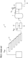
- FIG. 1 shows an embodiment of the inventive water electrolyser arrangement, comprising a purification assembly 1 and an electrolyser 2.
- a raw water source such as a groundwater well delivers raw water W raw , i.e. water with impurities of various kinds.
- Purification of the raw water W raw commences with an aeration stage.
- the aeration stage comprises a direct oxygenation vessel 10, realised as a large vessel with an inlet 101 into which the raw water W raw is pumped at a suitable rate.
- An aeration inlet 102 receives gaseous oxygen O 2 from the electrolyser 2, and the gaseous oxygen is allowed to rise through the raw water W raw in the direct oxygenation vessel 10, thereby increasing the level of dissolved oxygen in the water.
- This stage contributes to purification by allowing dissolved metal ions to combine with the dissolved oxygen, facilitating precipitation of such impurities.
- an aerator 104 can be arranged at the base of the vessel 10 as shown in Figure 2 .
- the gaseous oxygen arriving at the aeration inlet 102 is fed to the aerator 104.
- This can be a bubble aerator as indicated here, with a diffuser membrane 105 that limits the bubble size.
- the membrane can be realized to produce micro-bubbles with a favourably small diameter of less than 2 mm, for example. The smaller bubble size reduces the rate at which the bubbles (shown here greatly enlarged) rise through the water, thereby increasing the likelihood of ion-bonding and precipitation.
- the aerated water W aer leaving through the outlet 103 of the direct oxygenation vessel 10 proceeds to a filtration stage 12 and a demineralization stage 13.
- the demineralized water W demin is sufficiently pure for use as feed water for the water electrolyser 2.
- the demineralisation stage 13 can be equipped with a pump to control flow-rate and pressure of the purified water to the electrolyser 2.
- the water electrolyser 2 operates to split the feed water W demin into its gaseous constituents, hydrogen H 2 and oxygen O 2 .
- the economically valuable hydrogen H 2 can be output to an export pipeline.
- the oxygen O 2 in contrast is fed back to the purification assembly 1 and is used to aerate the raw water W raw in the direct oxygenation vessel 10.
- FIG. 3 shows a further embodiment of the inventive water electrolyser arrangement 1.
- the purification stage 1 also includes a small cascade aerator 11, with only a few steps, in this case only three steps.
- the partially aerated water leaving through the outlet 103 of the direct oxygenation vessel 10 is routed to the uppermost step of the cascade aerator 11.
- the more thoroughly aerated water W aer proceeds to the filtration and demineralization stages 12, 13.
- the demineralized water W demin is now sufficiently pure for use as feed water for the water electrolyser 2.
- the purified water W demin is collected in a storage tank 14.
- An outlet of the storage tank 14 is connected to the feed water inlet 21 of the electrolyser 2. Electrolysis commences after a suitable reserve of purified water W demin has accumulated.
- FIG 4 shows a further embodiment of the inventive water electrolyser arrangement 1.
- a buffer tank in this case the same tank that will be used as the storage tank 14 for demineralized water as explained above.
- the tank 14 - acting as a temporary aeration stage - can hold as much aerated water W aer as required for the electrolyser to start up and commence production of gaseous hydrogen and oxygen, or can be replenished as necessary.
- the aerated water W aer is fed to the demineralization stage 13, and the demineralized water Wdemin is fed to the electrolyser 2 as explained in Figure 1 and Figure 3 above.
- the input stages 10, 11, 12 are not used.
- the aeration vessel (and cascade aerator 11) take over as aeration stage 1 aer , and the demineralization stage 13 is fed from the sand filter 12 instead of from the buffer tank 14.
- the input to the buffer tank 14 now comes from the demineralization stage 13, and the output of the buffer tank 14 is connected to the feed water inlet 21 of the electrolyser 2.
- FIG. 5 shows a prior art water electrolyser arrangement 5.
- a raw water source such as a groundwater well delivers raw water W raw , i.e. water with impurities of various kinds.
- purification of the raw water commences with aeration using a cascade 51 constructed to have a suitable number of wide steps to aerate the raw water.
- the aerated water W aer is then filtered and demineralized as explained above, using a filter stage 52 and a demineralization stage 53, with a storage tank 54 for storing a reserve of demineralized water W demin .
- the cost of the cascade aerator 51 - which must be sufficiently wide and also high enough to accommodate the required number of steps - can be significant.
- the electrolyser 2 performs water electrolysis on the demineralized water W demin and exports hydrogen gas in a hydrogen outlet 22.
- electrolyser 2 is constructed to comprise a vent 23 for venting the waste oxygen to the atmosphere.
Landscapes
- Chemical & Material Sciences (AREA)
- Engineering & Computer Science (AREA)
- Chemical Kinetics & Catalysis (AREA)
- Electrochemistry (AREA)
- Materials Engineering (AREA)
- Metallurgy (AREA)
- Organic Chemistry (AREA)
- Inorganic Chemistry (AREA)
- Electrolytic Production Of Non-Metals, Compounds, Apparatuses Therefor (AREA)
Abstract
The invention describes a water electrolysis arrangement comprising a water electrolyser (2) with a feed water inlet (21), a hydrogen outlet (22) and an oxygen outlet (23); and a water purifier assembly (1) adapted for connection between a raw water source and the feed water inlet (21) of the water electrolyser (2), and comprising an aeration stage (1aer) for aerating raw water (Wraw); characterized in that the aeration stage (1aer) comprises an aeration vessel (10) with a raw water inlet (101) arranged to convey raw water (Wraw) from the raw water source into the aeration vessel (10); an aeration inlet (102) connected to the oxygen outlet (23) of the water electrolyser (2); and an aerated water outlet (103) arranged to convey aerated water (Waer) to a subsequent stage of the water purifier assembly (1). The invention further describes a method of performing water electrolysis using such a water electrolysis arrangement (1).
Description
- In water electrolysis, feed water is split into its constituent gases, i.e. hydrogen and oxygen. The purpose of water electrolysis is usually to obtain pure hydrogen gas, for a variety of commercial uses.
- The feed water should be relatively pure, so that the water electrolyser can operate efficiently. Furthermore, certain types of contaminants (e.g. calcium or iron species) should be removed in a demineralisation step to avoid damage to the water electrolyser.
- For these reasons, raw water (e.g. groundwater or well water) is first purified in a process which involves a number of stages. In an established configuration, water purification comprises a filtration stage in which particulate contaminants are removed, and a subsequent demineralization stage to remove metals ions (e.g. iron, copper etc.) from the water. Prior to the filtration stage, it is usual to aerate the raw water, for example using an aeration cascade or "cascade aerator", so that oxygen in the air can bind with ions in the raw water. The resulting mineral oxides precipitate out of the water. An aeration cascade is essentially a sequence of steps or plunge pools, constructed so that water flows from the uppermost level over each of the steps, to the lowest level. Aeration of the water is facilitated by turbulence and splashing as the water falls from one step to the next lower step. The effectiveness of the aeration cascade depends on the number of steps, the height of each step, and the depth of the plunge pool at each step. Because of its space requirements, a large cascade aerator can be a significant cost factor in a water electrolyser arrangement.
- It is therefore an object of the invention to provide a more economical way of realizing a water electrolyser arrangement.
- This object is achieved by the claimed water electrolysis arrangement, and by the claimed method of performing water electrolysis.
- As explained above, a water electrolyser breaks down water (received through a feed inlet) into its constituent gases hydrogen and oxygen, which exit the water electrolyser through separate outlets. The hydrogen outlet can feed into an export pipeline, for example. In the prior art arrangements described above, the oxygen gas produced during water electrolysis has little or no economic value and is generally regarded as a waste product. An oxygen outlet of a prior art water electrolyser arrangement is generally a vent that is open to the atmosphere.
- According to the invention, the water electrolysis arrangement comprises a water electrolyser and a water purifier assembly for installation between a raw water source and the feed water inlet of the water electrolyser. The water purifier assembly comprises at least an aeration means for aerating raw water. The aeration means comprises an aeration vessel with a raw water inlet for connection to the raw water source, and an outlet connected to a subsequent stage of the water purifier assembly. The aeration inlet of the aeration means is connected to the oxygen outlet of the water electrolyser.
- An advantage of the inventive water electrolyser arrangement is that the cost of water aeration can be significantly reduced. For example, the inventive water electrolyser arrangement does not need a large and costly aeration cascade of the type described above. Instead, the oxygen produced by the water electrolyser is fully utilized in the important step of aerating the raw water.
- Particularly advantageous embodiments and features of the invention are given by the dependent claims, as revealed in the following description. Features of different claim categories may be combined as appropriate to give further embodiments not described herein.
- In the following, without restricting the invention in any way, it may be assumed that the raw water is non-saline, and that the raw water source is a groundwater well or similar.
- The expressions "water electrolyser" and "electrolyser" shall be understood to be synonyms and may be used interchangeably herein. In the following, without restricting the invention in any way, it may be assumed that the water electrolyser comprises a number of electrolyser modules, for example proton exchange membrane (PEM) electrolyser modules, alkaline electrolyser modules, solid oxide electrolyser cells (SOEC), etc. The inventive water electrolyser arrangement may be assumed to also comprise a filtration stage arranged in the feed water line. This filtration stage can be realised as a sand filter, for example, to remove particulate and organic impurities from the water. The inventive water electrolyser arrangement may be assumed to also comprise a demineralisation stage (or "deionizing stage") downstream of the filtration stage to remove last impurities from the feed water. The demineralisation stage may deploy suitable ion-exchange resins and/or ion-exchange membranes to remove mineral ions from the filtered water. The "water purifier" of the water electrolyser arrangement shall be understood to comprise all purification stages, i.e. the aeration, filtration and demineralization stages.
- As explained above, aeration of the raw water is required in order to precipitate dissolved metal ions from the water. To increase the effectiveness of the oxygen, in a preferred embodiment of the invention the aeration inlet is arranged at the base of the aeration vessel, thus maximising the distance for the oxygen to travel as it rises to the surface of the water. The aeration vessel can have a suitable shape, for example an essentially cylindrical vessel with a height in the order of 2 m and a diameter in the order of 0.5 m. Preferably, the capacity of the aeration vessel is in the order of 500 - 5,000 litres. Of course, the total capacity of the aeration stage can be achieved by using two or more aeration vessels, each connected "in parallel" to the electrolyser oxygen outlet.
- Aeration of the raw water using oxygen from the aeration inlet can be done in a number of ways. For example, the aeration vessel can be adapted to accommodate a jet aerator, and the aeration inlet can feed into the air nozzle of the jet aerator. In a preferred embodiment of the invention, the aeration vessel is adapted to accommodate a bubble aerator, and the aeration inlet is arranged to feed into the bubble aerator. Preferably, the bubble aerator is realized to create fine bubbles (with a diameter less than 2 mm), for example by deploying a suitable diffuser membrane. Since oxygenation of the water takes place directly in the vessel, this vessel may be referred to in the following as a "direct oxygenation vessel".
- The effectiveness of the aeration can depend on the pressure of the oxygen arriving at the aeration inlet. If the water electrolysis arrangement deploys an electrolyser with a high operating pressure, for example 30 bar, the pressure of the oxygen being fed into the aeration vessel is sufficient to achieve thorough aeration of the feed water. However, the water electrolysis arrangement may deploy an electrolyser with a low operating pressure. Therefore, to achieve effective aeration of the feed water in such an embodiment, the water electrolyser arrangement preferably comprises a compressor between the oxygen outlet of the water electrolyser and the aeration inlet of the aeration vessel.
- The direct oxygenation vessel can achieve a satisfactory level of aeration, depending on the quality of the raw water input. In that case, the costs associated with purification of the raw water are favourably low, compared to an equivalent prior art water electrolyser arrangement which would require a large and therefore expensive aeration cascade.
- A demineralisation stage can in principle remove all impurities from the feed water, but if the level of impurity is too high, the demineralisation module will become clogged relatively quickly, interrupting the water treatment stage and resulting in downtime of the electrolyser stage. The quality of the raw water can be very poor in some locations. For example, an iron content of more than 1 mg per litre, or a manganese content of more than 0.1 mg per litre, is generally considered too high for a demineralisation module. In an installation that receives raw water with such unfavourably high levels of dissolved metal ions, the aeration stage of the inventive water electrolyser arrangement can be augmented by a small aeration cascade. For example, a favourably small three-step aeration cascade can provide sufficient additional aeration (i.e. removal of mineral impurities through oxidation and precipitation) to "top-up" the aeration level achieved by the direct oxygenation vessel. Here, the cost associated with purification of the raw water is still favourably low, since the combination of direct oxygenation vessel and a physically small aeration cascade is still less expensive than the large aeration cascade that would be required to aerate raw water containing high levels of dissolved mineral ions.
- The water treated in the purifier assembly can be input directly to the water electrolyser. However, since the flow rate of water through the purification stages may be incompatible with the intake rate of the electrolyser, in a preferred embodiment of the invention the purified or demineralised water is collected in a storage tank, and electrolysis commences after a suitable reserve of purified water has accumulated. An outlet of the storage tank is connected to the feed water inlet of the electrolyser.
- Until the electrolyser is up and running, the feed water can be aerated in a number of ways. For example, previously aerated water (from a different source) can be provided in a buffer tank connected to the feed water inlet of the electrolyser. The buffer tank can hold as much aerated water as required for the electrolyser to start up and commence production of gaseous hydrogen and oxygen. Such a buffer tank in the fluid line is in any case useful since it effectively decouples the water treatment stage from the electrolysis stage. If the water electrolysis arrangement includes a tank for storing purified water after aeration, filtering and demineralisation stages as described above, such a buffer tank can be initially filled with aerated and purified water so that the electrolyser can commence operation. The buffer tank is replenished with aerated water in order to provide a steady supply of feed water to the electrolyser in the relatively short time frame (e.g. an hour) during which the aeration vessel is waiting for oxygen from the electrolyser.
- Alternatively or in addition, aeration can be done using only a small cascade aerator as described above. This would allow the electrolyser to start up, initially at a low capacity due to the low water flow rate, which can be increased as the electrolyser outputs oxygen which in turn is used to aerate the feed water. Alternatively or in addition, a separate oxygen source can be deployed during an initial stage or start-up stage. For example, a compressed air supply can be connected to release oxygen into the aeration inlet of the aerator.
- Other objects and features of the present invention will become apparent from the following detailed descriptions considered in conjunction with the accompanying drawings. It is to be understood, however, that the drawings are designed solely for the purposes of illustration and not as a definition of the limits of the invention.
-
Figure 1 shows an embodiment of the inventive water electrolyser arrangement; -
Figure 2 shows a detail of the water electrolyser arrangement ofFigure 1 ; -
Figure 3 and Figure 4 show a further embodiment of the inventive water electrolyser arrangement; -
Figure 5 shows a prior art water electrolyser arrangement. - In the diagrams, like numbers refer to like objects throughout. Objects in the diagrams are not necessarily drawn to scale.
-
Figure 1 shows an embodiment of the inventive water electrolyser arrangement, comprising apurification assembly 1 and anelectrolyser 2. A raw water source such as a groundwater well delivers raw water Wraw, i.e. water with impurities of various kinds. Purification of the raw water Wraw commences with an aeration stage. Here, the aeration stage comprises adirect oxygenation vessel 10, realised as a large vessel with aninlet 101 into which the raw water Wraw is pumped at a suitable rate. Anaeration inlet 102 receives gaseous oxygen O2 from theelectrolyser 2, and the gaseous oxygen is allowed to rise through the raw water Wraw in thedirect oxygenation vessel 10, thereby increasing the level of dissolved oxygen in the water. This stage contributes to purification by allowing dissolved metal ions to combine with the dissolved oxygen, facilitating precipitation of such impurities. - Instead of simply allowing the received gaseous oxygen to rise through the raw water Wraw in the
direct oxygenation vessel 10, solution of the oxygen in the raw water Wraw can be encouraged. For example, anaerator 104 can be arranged at the base of thevessel 10 as shown inFigure 2 . Here, the gaseous oxygen arriving at theaeration inlet 102 is fed to theaerator 104. This can be a bubble aerator as indicated here, with adiffuser membrane 105 that limits the bubble size. The membrane can be realized to produce micro-bubbles with a favourably small diameter of less than 2 mm, for example. The smaller bubble size reduces the rate at which the bubbles (shown here greatly enlarged) rise through the water, thereby increasing the likelihood of ion-bonding and precipitation. - The aerated water Waer leaving through the
outlet 103 of thedirect oxygenation vessel 10 proceeds to afiltration stage 12 and ademineralization stage 13. The demineralized water Wdemin is sufficiently pure for use as feed water for thewater electrolyser 2. Thedemineralisation stage 13 can be equipped with a pump to control flow-rate and pressure of the purified water to theelectrolyser 2. - The
water electrolyser 2 operates to split the feed water Wdemin into its gaseous constituents, hydrogen H2 and oxygen O2. The economically valuable hydrogen H2 can be output to an export pipeline. The oxygen O2 in contrast is fed back to thepurification assembly 1 and is used to aerate the raw water Wraw in thedirect oxygenation vessel 10. - Depending on the quality of the raw water Wraw, the above embodiment can achieve a sufficient level of aeration. However, some raw water sources can have very high levels of impurities.
Figure 3 shows a further embodiment of the inventivewater electrolyser arrangement 1. Here, thepurification stage 1 also includes asmall cascade aerator 11, with only a few steps, in this case only three steps. The partially aerated water leaving through theoutlet 103 of thedirect oxygenation vessel 10 is routed to the uppermost step of thecascade aerator 11. At the base of thecascade aerator 11, the more thoroughly aerated water Waer proceeds to the filtration and demineralization stages 12, 13. Even though the raw water Wraw is of poor quality, the demineralized water Wdemin is now sufficiently pure for use as feed water for thewater electrolyser 2. - In this embodiment, the purified water Wdemin is collected in a
storage tank 14. An outlet of thestorage tank 14 is connected to thefeed water inlet 21 of theelectrolyser 2. Electrolysis commences after a suitable reserve of purified water Wdemin has accumulated. -
Figure 4 shows a further embodiment of the inventivewater electrolyser arrangement 1. Until the electrolyser is up and running, previously aerated water (from a different source) is provided in a buffer tank, in this case the same tank that will be used as thestorage tank 14 for demineralized water as explained above. The tank 14 - acting as a temporary aeration stage - can hold as much aerated water Waer as required for the electrolyser to start up and commence production of gaseous hydrogen and oxygen, or can be replenished as necessary. The aerated water Waer is fed to thedemineralization stage 13, and the demineralized water Wdemin is fed to theelectrolyser 2 as explained inFigure 1 andFigure 3 above. Until theelectrolyser 2 is running at capacity, the input stages 10, 11, 12 are not used. Once theelectrolyser 2 is generating sufficient oxygen at itsoutlet 23, the aeration vessel (and cascade aerator 11) take over asaeration stage 1aer, and thedemineralization stage 13 is fed from thesand filter 12 instead of from thebuffer tank 14. The input to thebuffer tank 14 now comes from thedemineralization stage 13, and the output of thebuffer tank 14 is connected to thefeed water inlet 21 of theelectrolyser 2. -
Figure 5 shows a prior art water electrolyser arrangement 5. A raw water source such as a groundwater well delivers raw water Wraw, i.e. water with impurities of various kinds. Here, purification of the raw water commences with aeration using acascade 51 constructed to have a suitable number of wide steps to aerate the raw water. The aerated water Waer is then filtered and demineralized as explained above, using afilter stage 52 and ademineralization stage 53, with a storage tank 54 for storing a reserve of demineralized water Wdemin. The cost of the cascade aerator 51 - which must be sufficiently wide and also high enough to accommodate the required number of steps - can be significant. Theelectrolyser 2 performs water electrolysis on the demineralized water Wdemin and exports hydrogen gas in ahydrogen outlet 22. Here,electrolyser 2 is constructed to comprise avent 23 for venting the waste oxygen to the atmosphere. - Although the present invention has been disclosed in the form of preferred embodiments and variations thereon, it will be understood that numerous additional modifications and variations could be made thereto without departing from the scope of the invention.
- For the sake of clarity, it is to be understood that the use of "a" or "an" throughout this application does not exclude a plurality, and "comprising" does not exclude other steps or elements.
Claims (14)
- A water electrolysis arrangement comprising- a water electrolyser (2) with a feed water inlet (21), a hydrogen outlet (22) and an oxygen outlet (23); and- a water purifier assembly (1) adapted for connection between a raw water source and the feed water inlet (21) of the water electrolyser (2), and comprising an aeration stage (1aer) for aerating raw water (Wraw);characterized in that
the aeration stage (1aer) comprises an aeration vessel (10) with- a raw water inlet (101) arranged to convey raw water (Wraw)from the raw water source into the aeration vessel (10) ;- an aeration inlet (102) connected to the oxygen outlet (23) of the water electrolyser (2); and- an aerated water outlet (103) arranged to convey aerated water (Waer) to a subsequent stage of the water purifier assembly (1). - A water electrolysis arrangement according to the preceding claim, wherein the aeration inlet (102) is arranged at the base of the aeration vessel (10).
- A water electrolysis arrangement according to any of the preceding claims, comprising a compressor between the oxygen outlet (23) of the water electrolyser (2) and the aeration inlet (102) of the aeration vessel (10).
- A water electrolysis arrangement according to any of the preceding claims, wherein the aeration vessel (10) is adapted to accommodate a bubble aerator (104), and the aeration inlet (102) is arranged to feed into the bubble aerator (104).
- A water electrolysis arrangement according to the preceding claim, wherein the bubble aerator (104) comprises a diffuser membrane (105) adapted to achieve a bubble size of less than 2 mm.
- A water electrolysis arrangement according to any of the preceding claims, wherein the aeration stage (1aer) comprises an aeration cascade (11) arranged between the aeration vessel (10) and the feed water line (21).
- A water electrolysis arrangement according to any of the preceding claims, wherein the aeration cascade (11) comprises three steps.
- A water electrolysis arrangement according to any of the preceding claims, wherein the water electrolyser (2) comprises any of: a PEM electrolyser module, an alkaline electrolyser, a solid oxide electrolyser.
- A water electrolysis arrangement according to any of the preceding claims, wherein the aeration vessel (10) has a capacity in the order of 500 - 5,000 litres.
- A water electrolysis arrangement according to any of the preceding claims, comprising a filtration stage (12) arranged in the feed water line.
- A water electrolysis arrangement according to any of the preceding claims, comprising a demineralisation stage (13) downstream of the filtration stage (12).
- A water electrolysis arrangement according to any of the preceding claims, comprising a demineralized water storage tank (14) arranged in the feed water line.
- A method of performing water electrolysis using a water electrolysis arrangement (1) according to any of claims 1 to 12, comprising the steps of- aerating raw water (Wraw)using oxygen produced by the water electrolyser (2);- conveying the aerated water (Waer) into the feed line of the water electrolysis arrangement (1); and- performing water electrolysis on the aerated water (Waer).
- A method according to the preceding claim, comprising an initial step of providing aerated water (Waer) from an alternative source until sufficient oxygen is present in the oxygen outlet (23) of the water electrolysis arrangement (1).
Priority Applications (1)
| Application Number | Priority Date | Filing Date | Title |
|---|---|---|---|
| EP23198228.1A EP4527983A1 (en) | 2023-09-19 | 2023-09-19 | Water electrolysis arrangement |
Applications Claiming Priority (1)
| Application Number | Priority Date | Filing Date | Title |
|---|---|---|---|
| EP23198228.1A EP4527983A1 (en) | 2023-09-19 | 2023-09-19 | Water electrolysis arrangement |
Publications (1)
| Publication Number | Publication Date |
|---|---|
| EP4527983A1 true EP4527983A1 (en) | 2025-03-26 |
Family
ID=88098341
Family Applications (1)
| Application Number | Title | Priority Date | Filing Date |
|---|---|---|---|
| EP23198228.1A Withdrawn EP4527983A1 (en) | 2023-09-19 | 2023-09-19 | Water electrolysis arrangement |
Country Status (1)
| Country | Link |
|---|---|
| EP (1) | EP4527983A1 (en) |
Citations (3)
| Publication number | Priority date | Publication date | Assignee | Title |
|---|---|---|---|---|
| JPH05135783A (en) * | 1991-07-04 | 1993-06-01 | Shimizu Corp | Energy feeding/utilizing facilities |
| JP2017052987A (en) * | 2015-09-08 | 2017-03-16 | 積水化学工業株式会社 | Water electrolysis apparatus and water electrolysis method |
| WO2023161611A1 (en) * | 2022-02-24 | 2023-08-31 | Ceres Intellectual Property Company Limited | Treatment plant electrolyser system |
-
2023
- 2023-09-19 EP EP23198228.1A patent/EP4527983A1/en not_active Withdrawn
Patent Citations (3)
| Publication number | Priority date | Publication date | Assignee | Title |
|---|---|---|---|---|
| JPH05135783A (en) * | 1991-07-04 | 1993-06-01 | Shimizu Corp | Energy feeding/utilizing facilities |
| JP2017052987A (en) * | 2015-09-08 | 2017-03-16 | 積水化学工業株式会社 | Water electrolysis apparatus and water electrolysis method |
| WO2023161611A1 (en) * | 2022-02-24 | 2023-08-31 | Ceres Intellectual Property Company Limited | Treatment plant electrolyser system |
Similar Documents
| Publication | Publication Date | Title |
|---|---|---|
| JP5908186B2 (en) | Water treatment method and water treatment apparatus using membrane | |
| JP7044848B1 (en) | Liquid treatment equipment, pure water production system and liquid treatment method | |
| JPS62273095A (en) | Water treatment plant | |
| MX2007014625A (en) | Dissolved air floatation with filter system. | |
| JP4119040B2 (en) | Functional water production method and apparatus | |
| JP2012170841A (en) | Compound desalination system | |
| CN215048848U (en) | Ozone air flotation device | |
| JP4365734B2 (en) | Membrane separation sewage treatment apparatus and operation method thereof | |
| KR102119504B1 (en) | Method and apparatus of reusing waste water using reverse osmosis | |
| US11492275B2 (en) | Water treatment device and water treatment method | |
| CN217051819U (en) | Pure water reverse osmosis system | |
| CN217323605U (en) | Treatment system for regeneration wastewater in production of hydrogen peroxide by anthraquinone process | |
| US5034127A (en) | Filter assembly for purifying brine | |
| CA1164356A (en) | Reverse osmosis unit-degasifier system | |
| CN216972179U (en) | High-precision treatment system for high-salt organic wastewater | |
| US4746441A (en) | Method of purifying brine for electrolytic chemical production | |
| JP4493371B2 (en) | Concentration separation method of sludge | |
| HU182096B (en) | Method and equipment for cleaning and/or airing water | |
| JP3087914B2 (en) | Aeration treatment equipment | |
| CN113233653A (en) | Treatment system and method for treating high-salinity organic wastewater with high precision | |
| CN218465601U (en) | Bipolar membrane feeding brine refining device in salt lake lithium extraction system | |
| JP3100504B2 (en) | Demineralized water production equipment | |
| JP7664333B2 (en) | Pure water production method and production equipment, pure water production method and pure water production system | |
| CN118206245B (en) | A wastewater treatment method | |
| CN221412722U (en) | A multi-component gas step-by-step purification and separation device |
Legal Events
| Date | Code | Title | Description |
|---|---|---|---|
| PUAI | Public reference made under article 153(3) epc to a published international application that has entered the european phase |
Free format text: ORIGINAL CODE: 0009012 |
|
| STAA | Information on the status of an ep patent application or granted ep patent |
Free format text: STATUS: THE APPLICATION HAS BEEN PUBLISHED |
|
| AK | Designated contracting states |
Kind code of ref document: A1 Designated state(s): AL AT BE BG CH CY CZ DE DK EE ES FI FR GB GR HR HU IE IS IT LI LT LU LV MC ME MK MT NL NO PL PT RO RS SE SI SK SM TR |
|
| STAA | Information on the status of an ep patent application or granted ep patent |
Free format text: STATUS: THE APPLICATION IS DEEMED TO BE WITHDRAWN |
|
| 18D | Application deemed to be withdrawn |
Effective date: 20250927 |