EP4527979A1 - Rigid-film-coated object, machine component, and bearing - Google Patents
Rigid-film-coated object, machine component, and bearing Download PDFInfo
- Publication number
- EP4527979A1 EP4527979A1 EP23807628.5A EP23807628A EP4527979A1 EP 4527979 A1 EP4527979 A1 EP 4527979A1 EP 23807628 A EP23807628 A EP 23807628A EP 4527979 A1 EP4527979 A1 EP 4527979A1
- Authority
- EP
- European Patent Office
- Prior art keywords
- hard film
- film
- hydrogen
- coating film
- base material
- Prior art date
- Legal status (The legal status is an assumption and is not a legal conclusion. Google has not performed a legal analysis and makes no representation as to the accuracy of the status listed.)
- Pending
Links
Images



Classifications
-
- C—CHEMISTRY; METALLURGY
- C23—COATING METALLIC MATERIAL; COATING MATERIAL WITH METALLIC MATERIAL; CHEMICAL SURFACE TREATMENT; DIFFUSION TREATMENT OF METALLIC MATERIAL; COATING BY VACUUM EVAPORATION, BY SPUTTERING, BY ION IMPLANTATION OR BY CHEMICAL VAPOUR DEPOSITION, IN GENERAL; INHIBITING CORROSION OF METALLIC MATERIAL OR INCRUSTATION IN GENERAL
- C23C—COATING METALLIC MATERIAL; COATING MATERIAL WITH METALLIC MATERIAL; SURFACE TREATMENT OF METALLIC MATERIAL BY DIFFUSION INTO THE SURFACE, BY CHEMICAL CONVERSION OR SUBSTITUTION; COATING BY VACUUM EVAPORATION, BY SPUTTERING, BY ION IMPLANTATION OR BY CHEMICAL VAPOUR DEPOSITION, IN GENERAL
- C23C30/00—Coating with metallic material characterised only by the composition of the metallic material, i.e. not characterised by the coating process
-
- C—CHEMISTRY; METALLURGY
- C23—COATING METALLIC MATERIAL; COATING MATERIAL WITH METALLIC MATERIAL; CHEMICAL SURFACE TREATMENT; DIFFUSION TREATMENT OF METALLIC MATERIAL; COATING BY VACUUM EVAPORATION, BY SPUTTERING, BY ION IMPLANTATION OR BY CHEMICAL VAPOUR DEPOSITION, IN GENERAL; INHIBITING CORROSION OF METALLIC MATERIAL OR INCRUSTATION IN GENERAL
- C23C—COATING METALLIC MATERIAL; COATING MATERIAL WITH METALLIC MATERIAL; SURFACE TREATMENT OF METALLIC MATERIAL BY DIFFUSION INTO THE SURFACE, BY CHEMICAL CONVERSION OR SUBSTITUTION; COATING BY VACUUM EVAPORATION, BY SPUTTERING, BY ION IMPLANTATION OR BY CHEMICAL VAPOUR DEPOSITION, IN GENERAL
- C23C14/00—Coating by vacuum evaporation, by sputtering or by ion implantation of the coating forming material
- C23C14/0021—Reactive sputtering or evaporation
- C23C14/0036—Reactive sputtering
-
- C—CHEMISTRY; METALLURGY
- C23—COATING METALLIC MATERIAL; COATING MATERIAL WITH METALLIC MATERIAL; CHEMICAL SURFACE TREATMENT; DIFFUSION TREATMENT OF METALLIC MATERIAL; COATING BY VACUUM EVAPORATION, BY SPUTTERING, BY ION IMPLANTATION OR BY CHEMICAL VAPOUR DEPOSITION, IN GENERAL; INHIBITING CORROSION OF METALLIC MATERIAL OR INCRUSTATION IN GENERAL
- C23C—COATING METALLIC MATERIAL; COATING MATERIAL WITH METALLIC MATERIAL; SURFACE TREATMENT OF METALLIC MATERIAL BY DIFFUSION INTO THE SURFACE, BY CHEMICAL CONVERSION OR SUBSTITUTION; COATING BY VACUUM EVAPORATION, BY SPUTTERING, BY ION IMPLANTATION OR BY CHEMICAL VAPOUR DEPOSITION, IN GENERAL
- C23C14/00—Coating by vacuum evaporation, by sputtering or by ion implantation of the coating forming material
- C23C14/02—Pretreatment of the material to be coated
- C23C14/027—Graded interfaces
-
- C—CHEMISTRY; METALLURGY
- C23—COATING METALLIC MATERIAL; COATING MATERIAL WITH METALLIC MATERIAL; CHEMICAL SURFACE TREATMENT; DIFFUSION TREATMENT OF METALLIC MATERIAL; COATING BY VACUUM EVAPORATION, BY SPUTTERING, BY ION IMPLANTATION OR BY CHEMICAL VAPOUR DEPOSITION, IN GENERAL; INHIBITING CORROSION OF METALLIC MATERIAL OR INCRUSTATION IN GENERAL
- C23C—COATING METALLIC MATERIAL; COATING MATERIAL WITH METALLIC MATERIAL; SURFACE TREATMENT OF METALLIC MATERIAL BY DIFFUSION INTO THE SURFACE, BY CHEMICAL CONVERSION OR SUBSTITUTION; COATING BY VACUUM EVAPORATION, BY SPUTTERING, BY ION IMPLANTATION OR BY CHEMICAL VAPOUR DEPOSITION, IN GENERAL
- C23C14/00—Coating by vacuum evaporation, by sputtering or by ion implantation of the coating forming material
- C23C14/06—Coating by vacuum evaporation, by sputtering or by ion implantation of the coating forming material characterised by the coating material
- C23C14/0605—Carbon
-
- C—CHEMISTRY; METALLURGY
- C23—COATING METALLIC MATERIAL; COATING MATERIAL WITH METALLIC MATERIAL; CHEMICAL SURFACE TREATMENT; DIFFUSION TREATMENT OF METALLIC MATERIAL; COATING BY VACUUM EVAPORATION, BY SPUTTERING, BY ION IMPLANTATION OR BY CHEMICAL VAPOUR DEPOSITION, IN GENERAL; INHIBITING CORROSION OF METALLIC MATERIAL OR INCRUSTATION IN GENERAL
- C23C—COATING METALLIC MATERIAL; COATING MATERIAL WITH METALLIC MATERIAL; SURFACE TREATMENT OF METALLIC MATERIAL BY DIFFUSION INTO THE SURFACE, BY CHEMICAL CONVERSION OR SUBSTITUTION; COATING BY VACUUM EVAPORATION, BY SPUTTERING, BY ION IMPLANTATION OR BY CHEMICAL VAPOUR DEPOSITION, IN GENERAL
- C23C14/00—Coating by vacuum evaporation, by sputtering or by ion implantation of the coating forming material
- C23C14/06—Coating by vacuum evaporation, by sputtering or by ion implantation of the coating forming material characterised by the coating material
- C23C14/0635—Carbides
-
- C—CHEMISTRY; METALLURGY
- C23—COATING METALLIC MATERIAL; COATING MATERIAL WITH METALLIC MATERIAL; CHEMICAL SURFACE TREATMENT; DIFFUSION TREATMENT OF METALLIC MATERIAL; COATING BY VACUUM EVAPORATION, BY SPUTTERING, BY ION IMPLANTATION OR BY CHEMICAL VAPOUR DEPOSITION, IN GENERAL; INHIBITING CORROSION OF METALLIC MATERIAL OR INCRUSTATION IN GENERAL
- C23C—COATING METALLIC MATERIAL; COATING MATERIAL WITH METALLIC MATERIAL; SURFACE TREATMENT OF METALLIC MATERIAL BY DIFFUSION INTO THE SURFACE, BY CHEMICAL CONVERSION OR SUBSTITUTION; COATING BY VACUUM EVAPORATION, BY SPUTTERING, BY ION IMPLANTATION OR BY CHEMICAL VAPOUR DEPOSITION, IN GENERAL
- C23C14/00—Coating by vacuum evaporation, by sputtering or by ion implantation of the coating forming material
- C23C14/22—Coating by vacuum evaporation, by sputtering or by ion implantation of the coating forming material characterised by the process of coating
- C23C14/34—Sputtering
- C23C14/35—Sputtering by application of a magnetic field, e.g. magnetron sputtering
- C23C14/352—Sputtering by application of a magnetic field, e.g. magnetron sputtering using more than one target
-
- C—CHEMISTRY; METALLURGY
- C23—COATING METALLIC MATERIAL; COATING MATERIAL WITH METALLIC MATERIAL; CHEMICAL SURFACE TREATMENT; DIFFUSION TREATMENT OF METALLIC MATERIAL; COATING BY VACUUM EVAPORATION, BY SPUTTERING, BY ION IMPLANTATION OR BY CHEMICAL VAPOUR DEPOSITION, IN GENERAL; INHIBITING CORROSION OF METALLIC MATERIAL OR INCRUSTATION IN GENERAL
- C23C—COATING METALLIC MATERIAL; COATING MATERIAL WITH METALLIC MATERIAL; SURFACE TREATMENT OF METALLIC MATERIAL BY DIFFUSION INTO THE SURFACE, BY CHEMICAL CONVERSION OR SUBSTITUTION; COATING BY VACUUM EVAPORATION, BY SPUTTERING, BY ION IMPLANTATION OR BY CHEMICAL VAPOUR DEPOSITION, IN GENERAL
- C23C18/00—Chemical coating by decomposition of either liquid compounds or solutions of the coating forming compounds, without leaving reaction products of surface material in the coating; Contact plating
- C23C18/16—Chemical coating by decomposition of either liquid compounds or solutions of the coating forming compounds, without leaving reaction products of surface material in the coating; Contact plating by reduction or substitution, e.g. electroless plating
- C23C18/31—Coating with metals
- C23C18/32—Coating with nickel, cobalt or mixtures thereof with phosphorus or boron
- C23C18/34—Coating with nickel, cobalt or mixtures thereof with phosphorus or boron using reducing agents
-
- C—CHEMISTRY; METALLURGY
- C23—COATING METALLIC MATERIAL; COATING MATERIAL WITH METALLIC MATERIAL; CHEMICAL SURFACE TREATMENT; DIFFUSION TREATMENT OF METALLIC MATERIAL; COATING BY VACUUM EVAPORATION, BY SPUTTERING, BY ION IMPLANTATION OR BY CHEMICAL VAPOUR DEPOSITION, IN GENERAL; INHIBITING CORROSION OF METALLIC MATERIAL OR INCRUSTATION IN GENERAL
- C23C—COATING METALLIC MATERIAL; COATING MATERIAL WITH METALLIC MATERIAL; SURFACE TREATMENT OF METALLIC MATERIAL BY DIFFUSION INTO THE SURFACE, BY CHEMICAL CONVERSION OR SUBSTITUTION; COATING BY VACUUM EVAPORATION, BY SPUTTERING, BY ION IMPLANTATION OR BY CHEMICAL VAPOUR DEPOSITION, IN GENERAL
- C23C28/00—Coating for obtaining at least two superposed coatings either by methods not provided for in a single one of groups C23C2/00 - C23C26/00 or by combinations of methods provided for in subclasses C23C and C25C or C25D
- C23C28/30—Coatings combining at least one metallic layer and at least one inorganic non-metallic layer
- C23C28/32—Coatings combining at least one metallic layer and at least one inorganic non-metallic layer including at least one pure metallic layer
-
- C—CHEMISTRY; METALLURGY
- C23—COATING METALLIC MATERIAL; COATING MATERIAL WITH METALLIC MATERIAL; CHEMICAL SURFACE TREATMENT; DIFFUSION TREATMENT OF METALLIC MATERIAL; COATING BY VACUUM EVAPORATION, BY SPUTTERING, BY ION IMPLANTATION OR BY CHEMICAL VAPOUR DEPOSITION, IN GENERAL; INHIBITING CORROSION OF METALLIC MATERIAL OR INCRUSTATION IN GENERAL
- C23C—COATING METALLIC MATERIAL; COATING MATERIAL WITH METALLIC MATERIAL; SURFACE TREATMENT OF METALLIC MATERIAL BY DIFFUSION INTO THE SURFACE, BY CHEMICAL CONVERSION OR SUBSTITUTION; COATING BY VACUUM EVAPORATION, BY SPUTTERING, BY ION IMPLANTATION OR BY CHEMICAL VAPOUR DEPOSITION, IN GENERAL
- C23C28/00—Coating for obtaining at least two superposed coatings either by methods not provided for in a single one of groups C23C2/00 - C23C26/00 or by combinations of methods provided for in subclasses C23C and C25C or C25D
- C23C28/30—Coatings combining at least one metallic layer and at least one inorganic non-metallic layer
- C23C28/32—Coatings combining at least one metallic layer and at least one inorganic non-metallic layer including at least one pure metallic layer
- C23C28/321—Coatings combining at least one metallic layer and at least one inorganic non-metallic layer including at least one pure metallic layer with at least one metal alloy layer
-
- C—CHEMISTRY; METALLURGY
- C23—COATING METALLIC MATERIAL; COATING MATERIAL WITH METALLIC MATERIAL; CHEMICAL SURFACE TREATMENT; DIFFUSION TREATMENT OF METALLIC MATERIAL; COATING BY VACUUM EVAPORATION, BY SPUTTERING, BY ION IMPLANTATION OR BY CHEMICAL VAPOUR DEPOSITION, IN GENERAL; INHIBITING CORROSION OF METALLIC MATERIAL OR INCRUSTATION IN GENERAL
- C23C—COATING METALLIC MATERIAL; COATING MATERIAL WITH METALLIC MATERIAL; SURFACE TREATMENT OF METALLIC MATERIAL BY DIFFUSION INTO THE SURFACE, BY CHEMICAL CONVERSION OR SUBSTITUTION; COATING BY VACUUM EVAPORATION, BY SPUTTERING, BY ION IMPLANTATION OR BY CHEMICAL VAPOUR DEPOSITION, IN GENERAL
- C23C28/00—Coating for obtaining at least two superposed coatings either by methods not provided for in a single one of groups C23C2/00 - C23C26/00 or by combinations of methods provided for in subclasses C23C and C25C or C25D
- C23C28/30—Coatings combining at least one metallic layer and at least one inorganic non-metallic layer
- C23C28/34—Coatings combining at least one metallic layer and at least one inorganic non-metallic layer including at least one inorganic non-metallic material layer, e.g. metal carbide, nitride, boride, silicide layer and their mixtures, enamels, phosphates and sulphates
-
- C—CHEMISTRY; METALLURGY
- C23—COATING METALLIC MATERIAL; COATING MATERIAL WITH METALLIC MATERIAL; CHEMICAL SURFACE TREATMENT; DIFFUSION TREATMENT OF METALLIC MATERIAL; COATING BY VACUUM EVAPORATION, BY SPUTTERING, BY ION IMPLANTATION OR BY CHEMICAL VAPOUR DEPOSITION, IN GENERAL; INHIBITING CORROSION OF METALLIC MATERIAL OR INCRUSTATION IN GENERAL
- C23C—COATING METALLIC MATERIAL; COATING MATERIAL WITH METALLIC MATERIAL; SURFACE TREATMENT OF METALLIC MATERIAL BY DIFFUSION INTO THE SURFACE, BY CHEMICAL CONVERSION OR SUBSTITUTION; COATING BY VACUUM EVAPORATION, BY SPUTTERING, BY ION IMPLANTATION OR BY CHEMICAL VAPOUR DEPOSITION, IN GENERAL
- C23C28/00—Coating for obtaining at least two superposed coatings either by methods not provided for in a single one of groups C23C2/00 - C23C26/00 or by combinations of methods provided for in subclasses C23C and C25C or C25D
- C23C28/30—Coatings combining at least one metallic layer and at least one inorganic non-metallic layer
- C23C28/34—Coatings combining at least one metallic layer and at least one inorganic non-metallic layer including at least one inorganic non-metallic material layer, e.g. metal carbide, nitride, boride, silicide layer and their mixtures, enamels, phosphates and sulphates
- C23C28/341—Coatings combining at least one metallic layer and at least one inorganic non-metallic layer including at least one inorganic non-metallic material layer, e.g. metal carbide, nitride, boride, silicide layer and their mixtures, enamels, phosphates and sulphates with at least one carbide layer
-
- C—CHEMISTRY; METALLURGY
- C23—COATING METALLIC MATERIAL; COATING MATERIAL WITH METALLIC MATERIAL; CHEMICAL SURFACE TREATMENT; DIFFUSION TREATMENT OF METALLIC MATERIAL; COATING BY VACUUM EVAPORATION, BY SPUTTERING, BY ION IMPLANTATION OR BY CHEMICAL VAPOUR DEPOSITION, IN GENERAL; INHIBITING CORROSION OF METALLIC MATERIAL OR INCRUSTATION IN GENERAL
- C23C—COATING METALLIC MATERIAL; COATING MATERIAL WITH METALLIC MATERIAL; SURFACE TREATMENT OF METALLIC MATERIAL BY DIFFUSION INTO THE SURFACE, BY CHEMICAL CONVERSION OR SUBSTITUTION; COATING BY VACUUM EVAPORATION, BY SPUTTERING, BY ION IMPLANTATION OR BY CHEMICAL VAPOUR DEPOSITION, IN GENERAL
- C23C28/00—Coating for obtaining at least two superposed coatings either by methods not provided for in a single one of groups C23C2/00 - C23C26/00 or by combinations of methods provided for in subclasses C23C and C25C or C25D
- C23C28/30—Coatings combining at least one metallic layer and at least one inorganic non-metallic layer
- C23C28/34—Coatings combining at least one metallic layer and at least one inorganic non-metallic layer including at least one inorganic non-metallic material layer, e.g. metal carbide, nitride, boride, silicide layer and their mixtures, enamels, phosphates and sulphates
- C23C28/343—Coatings combining at least one metallic layer and at least one inorganic non-metallic layer including at least one inorganic non-metallic material layer, e.g. metal carbide, nitride, boride, silicide layer and their mixtures, enamels, phosphates and sulphates with at least one DLC or an amorphous carbon based layer, the layer being doped or not
-
- C—CHEMISTRY; METALLURGY
- C23—COATING METALLIC MATERIAL; COATING MATERIAL WITH METALLIC MATERIAL; CHEMICAL SURFACE TREATMENT; DIFFUSION TREATMENT OF METALLIC MATERIAL; COATING BY VACUUM EVAPORATION, BY SPUTTERING, BY ION IMPLANTATION OR BY CHEMICAL VAPOUR DEPOSITION, IN GENERAL; INHIBITING CORROSION OF METALLIC MATERIAL OR INCRUSTATION IN GENERAL
- C23C—COATING METALLIC MATERIAL; COATING MATERIAL WITH METALLIC MATERIAL; SURFACE TREATMENT OF METALLIC MATERIAL BY DIFFUSION INTO THE SURFACE, BY CHEMICAL CONVERSION OR SUBSTITUTION; COATING BY VACUUM EVAPORATION, BY SPUTTERING, BY ION IMPLANTATION OR BY CHEMICAL VAPOUR DEPOSITION, IN GENERAL
- C23C8/00—Solid state diffusion of only non-metal elements into metallic material surfaces; Chemical surface treatment of metallic material by reaction of the surface with a reactive gas, leaving reaction products of surface material in the coating, e.g. conversion coatings, passivation of metals
- C23C8/06—Solid state diffusion of only non-metal elements into metallic material surfaces; Chemical surface treatment of metallic material by reaction of the surface with a reactive gas, leaving reaction products of surface material in the coating, e.g. conversion coatings, passivation of metals using gases
- C23C8/36—Solid state diffusion of only non-metal elements into metallic material surfaces; Chemical surface treatment of metallic material by reaction of the surface with a reactive gas, leaving reaction products of surface material in the coating, e.g. conversion coatings, passivation of metals using gases using ionised gases, e.g. ionitriding
-
- C—CHEMISTRY; METALLURGY
- C23—COATING METALLIC MATERIAL; COATING MATERIAL WITH METALLIC MATERIAL; CHEMICAL SURFACE TREATMENT; DIFFUSION TREATMENT OF METALLIC MATERIAL; COATING BY VACUUM EVAPORATION, BY SPUTTERING, BY ION IMPLANTATION OR BY CHEMICAL VAPOUR DEPOSITION, IN GENERAL; INHIBITING CORROSION OF METALLIC MATERIAL OR INCRUSTATION IN GENERAL
- C23C—COATING METALLIC MATERIAL; COATING MATERIAL WITH METALLIC MATERIAL; SURFACE TREATMENT OF METALLIC MATERIAL BY DIFFUSION INTO THE SURFACE, BY CHEMICAL CONVERSION OR SUBSTITUTION; COATING BY VACUUM EVAPORATION, BY SPUTTERING, BY ION IMPLANTATION OR BY CHEMICAL VAPOUR DEPOSITION, IN GENERAL
- C23C8/00—Solid state diffusion of only non-metal elements into metallic material surfaces; Chemical surface treatment of metallic material by reaction of the surface with a reactive gas, leaving reaction products of surface material in the coating, e.g. conversion coatings, passivation of metals
- C23C8/06—Solid state diffusion of only non-metal elements into metallic material surfaces; Chemical surface treatment of metallic material by reaction of the surface with a reactive gas, leaving reaction products of surface material in the coating, e.g. conversion coatings, passivation of metals using gases
- C23C8/36—Solid state diffusion of only non-metal elements into metallic material surfaces; Chemical surface treatment of metallic material by reaction of the surface with a reactive gas, leaving reaction products of surface material in the coating, e.g. conversion coatings, passivation of metals using gases using ionised gases, e.g. ionitriding
- C23C8/38—Treatment of ferrous surfaces
-
- C—CHEMISTRY; METALLURGY
- C23—COATING METALLIC MATERIAL; COATING MATERIAL WITH METALLIC MATERIAL; CHEMICAL SURFACE TREATMENT; DIFFUSION TREATMENT OF METALLIC MATERIAL; COATING BY VACUUM EVAPORATION, BY SPUTTERING, BY ION IMPLANTATION OR BY CHEMICAL VAPOUR DEPOSITION, IN GENERAL; INHIBITING CORROSION OF METALLIC MATERIAL OR INCRUSTATION IN GENERAL
- C23C—COATING METALLIC MATERIAL; COATING MATERIAL WITH METALLIC MATERIAL; SURFACE TREATMENT OF METALLIC MATERIAL BY DIFFUSION INTO THE SURFACE, BY CHEMICAL CONVERSION OR SUBSTITUTION; COATING BY VACUUM EVAPORATION, BY SPUTTERING, BY ION IMPLANTATION OR BY CHEMICAL VAPOUR DEPOSITION, IN GENERAL
- C23C8/00—Solid state diffusion of only non-metal elements into metallic material surfaces; Chemical surface treatment of metallic material by reaction of the surface with a reactive gas, leaving reaction products of surface material in the coating, e.g. conversion coatings, passivation of metals
- C23C8/80—After-treatment
-
- F—MECHANICAL ENGINEERING; LIGHTING; HEATING; WEAPONS; BLASTING
- F16—ENGINEERING ELEMENTS AND UNITS; GENERAL MEASURES FOR PRODUCING AND MAINTAINING EFFECTIVE FUNCTIONING OF MACHINES OR INSTALLATIONS; THERMAL INSULATION IN GENERAL
- F16C—SHAFTS; FLEXIBLE SHAFTS; ELEMENTS OR CRANKSHAFT MECHANISMS; ROTARY BODIES OTHER THAN GEARING ELEMENTS; BEARINGS
- F16C19/00—Bearings with rolling contact, for exclusively rotary movement
- F16C19/52—Bearings with rolling contact, for exclusively rotary movement with devices affected by abnormal or undesired conditions
-
- F—MECHANICAL ENGINEERING; LIGHTING; HEATING; WEAPONS; BLASTING
- F16—ENGINEERING ELEMENTS AND UNITS; GENERAL MEASURES FOR PRODUCING AND MAINTAINING EFFECTIVE FUNCTIONING OF MACHINES OR INSTALLATIONS; THERMAL INSULATION IN GENERAL
- F16C—SHAFTS; FLEXIBLE SHAFTS; ELEMENTS OR CRANKSHAFT MECHANISMS; ROTARY BODIES OTHER THAN GEARING ELEMENTS; BEARINGS
- F16C33/00—Parts of bearings; Special methods for making bearings or parts thereof
- F16C33/30—Parts of ball or roller bearings
- F16C33/32—Balls
-
- F—MECHANICAL ENGINEERING; LIGHTING; HEATING; WEAPONS; BLASTING
- F16—ENGINEERING ELEMENTS AND UNITS; GENERAL MEASURES FOR PRODUCING AND MAINTAINING EFFECTIVE FUNCTIONING OF MACHINES OR INSTALLATIONS; THERMAL INSULATION IN GENERAL
- F16C—SHAFTS; FLEXIBLE SHAFTS; ELEMENTS OR CRANKSHAFT MECHANISMS; ROTARY BODIES OTHER THAN GEARING ELEMENTS; BEARINGS
- F16C33/00—Parts of bearings; Special methods for making bearings or parts thereof
- F16C33/30—Parts of ball or roller bearings
- F16C33/58—Raceways; Race rings
- F16C33/62—Selection of substances
-
- C—CHEMISTRY; METALLURGY
- C23—COATING METALLIC MATERIAL; COATING MATERIAL WITH METALLIC MATERIAL; CHEMICAL SURFACE TREATMENT; DIFFUSION TREATMENT OF METALLIC MATERIAL; COATING BY VACUUM EVAPORATION, BY SPUTTERING, BY ION IMPLANTATION OR BY CHEMICAL VAPOUR DEPOSITION, IN GENERAL; INHIBITING CORROSION OF METALLIC MATERIAL OR INCRUSTATION IN GENERAL
- C23C—COATING METALLIC MATERIAL; COATING MATERIAL WITH METALLIC MATERIAL; SURFACE TREATMENT OF METALLIC MATERIAL BY DIFFUSION INTO THE SURFACE, BY CHEMICAL CONVERSION OR SUBSTITUTION; COATING BY VACUUM EVAPORATION, BY SPUTTERING, BY ION IMPLANTATION OR BY CHEMICAL VAPOUR DEPOSITION, IN GENERAL
- C23C18/00—Chemical coating by decomposition of either liquid compounds or solutions of the coating forming compounds, without leaving reaction products of surface material in the coating; Contact plating
- C23C18/16—Chemical coating by decomposition of either liquid compounds or solutions of the coating forming compounds, without leaving reaction products of surface material in the coating; Contact plating by reduction or substitution, e.g. electroless plating
- C23C18/1601—Process or apparatus
- C23C18/1633—Process of electroless plating
- C23C18/1689—After-treatment
- C23C18/1692—Heat-treatment
-
- F—MECHANICAL ENGINEERING; LIGHTING; HEATING; WEAPONS; BLASTING
- F16—ENGINEERING ELEMENTS AND UNITS; GENERAL MEASURES FOR PRODUCING AND MAINTAINING EFFECTIVE FUNCTIONING OF MACHINES OR INSTALLATIONS; THERMAL INSULATION IN GENERAL
- F16C—SHAFTS; FLEXIBLE SHAFTS; ELEMENTS OR CRANKSHAFT MECHANISMS; ROTARY BODIES OTHER THAN GEARING ELEMENTS; BEARINGS
- F16C2202/00—Solid materials defined by their properties
- F16C2202/02—Mechanical properties
- F16C2202/04—Hardness
-
- F—MECHANICAL ENGINEERING; LIGHTING; HEATING; WEAPONS; BLASTING
- F16—ENGINEERING ELEMENTS AND UNITS; GENERAL MEASURES FOR PRODUCING AND MAINTAINING EFFECTIVE FUNCTIONING OF MACHINES OR INSTALLATIONS; THERMAL INSULATION IN GENERAL
- F16C—SHAFTS; FLEXIBLE SHAFTS; ELEMENTS OR CRANKSHAFT MECHANISMS; ROTARY BODIES OTHER THAN GEARING ELEMENTS; BEARINGS
- F16C2204/00—Metallic materials; Alloys
- F16C2204/52—Alloys based on nickel, e.g. Inconel
-
- F—MECHANICAL ENGINEERING; LIGHTING; HEATING; WEAPONS; BLASTING
- F16—ENGINEERING ELEMENTS AND UNITS; GENERAL MEASURES FOR PRODUCING AND MAINTAINING EFFECTIVE FUNCTIONING OF MACHINES OR INSTALLATIONS; THERMAL INSULATION IN GENERAL
- F16C—SHAFTS; FLEXIBLE SHAFTS; ELEMENTS OR CRANKSHAFT MECHANISMS; ROTARY BODIES OTHER THAN GEARING ELEMENTS; BEARINGS
- F16C2206/00—Materials with ceramics, cermets, hard carbon or similar non-metallic hard materials as main constituents
- F16C2206/02—Carbon based material
- F16C2206/04—Diamond like carbon [DLC]
-
- F—MECHANICAL ENGINEERING; LIGHTING; HEATING; WEAPONS; BLASTING
- F16—ENGINEERING ELEMENTS AND UNITS; GENERAL MEASURES FOR PRODUCING AND MAINTAINING EFFECTIVE FUNCTIONING OF MACHINES OR INSTALLATIONS; THERMAL INSULATION IN GENERAL
- F16C—SHAFTS; FLEXIBLE SHAFTS; ELEMENTS OR CRANKSHAFT MECHANISMS; ROTARY BODIES OTHER THAN GEARING ELEMENTS; BEARINGS
- F16C2206/00—Materials with ceramics, cermets, hard carbon or similar non-metallic hard materials as main constituents
- F16C2206/80—Cermets, i.e. composites of ceramics and metal
- F16C2206/82—Cermets, i.e. composites of ceramics and metal based on tungsten carbide [WC]
-
- F—MECHANICAL ENGINEERING; LIGHTING; HEATING; WEAPONS; BLASTING
- F16—ENGINEERING ELEMENTS AND UNITS; GENERAL MEASURES FOR PRODUCING AND MAINTAINING EFFECTIVE FUNCTIONING OF MACHINES OR INSTALLATIONS; THERMAL INSULATION IN GENERAL
- F16C—SHAFTS; FLEXIBLE SHAFTS; ELEMENTS OR CRANKSHAFT MECHANISMS; ROTARY BODIES OTHER THAN GEARING ELEMENTS; BEARINGS
- F16C2223/00—Surface treatments; Hardening; Coating
- F16C2223/30—Coating surfaces
- F16C2223/70—Coating surfaces by electroplating or electrolytic coating, e.g. anodising, galvanising
-
- F—MECHANICAL ENGINEERING; LIGHTING; HEATING; WEAPONS; BLASTING
- F16—ENGINEERING ELEMENTS AND UNITS; GENERAL MEASURES FOR PRODUCING AND MAINTAINING EFFECTIVE FUNCTIONING OF MACHINES OR INSTALLATIONS; THERMAL INSULATION IN GENERAL
- F16C—SHAFTS; FLEXIBLE SHAFTS; ELEMENTS OR CRANKSHAFT MECHANISMS; ROTARY BODIES OTHER THAN GEARING ELEMENTS; BEARINGS
- F16C2240/00—Specified values or numerical ranges of parameters; Relations between them
- F16C2240/40—Linear dimensions, e.g. length, radius, thickness, gap
- F16C2240/60—Thickness, e.g. thickness of coatings
Definitions
- the present invention relates to a hard film formed body having a hard film on a surface of a base material, and a machine component and a bearing using the same.
- Such a machine component is often used in a hydrogen entering environment.
- a rolling component such as a rolling bearing and a gear
- water or the lubricant is decomposed to generate hydrogen.
- the hydrogen enters steel early damage due to hydrogen embrittlement might be caused.
- Patent Document 1 discloses a rolling component in which a steel material within a specified chemical component range is carbonitrided and fine-granulated so that carbonitride is dispersed and deposited. This configuration deals with the hydrogen embrittlement against trace hydrogen derived from lubricant.
- Patent Document 2 discloses a material resistant to hydrogen embrittlement. The material is formed of a Ni base alloy or a Fe-Ni base alloy and includes an aging part and a hydrogen embrittlement suppression layer exposed to hydrogen. The tensile strength of the aging part is more than 1,000 MPa.
- Patent Document 3 discloses a rolling bearing having a Ni coating film formed on a rolling surface.
- the rolling bearing of Patent Document 3 prevents hydrogen from entering steel of the bearing by the Ni coating film and suppresses a short-lifetime flaking by the hydrogen embrittlement, so that the lifetime of the rolling bearing is improved.
- Hydrogen does not generate carbon dioxide (CO 2 ) but only water when used as an energy source, so that hydrogen is expected as clean energy. It is expected that hydrogen is used widely in the whole society in future, and thus hydrogen usable devices (for example, a ball valve or a compressor for hydrogen stations) may become common. Machine components such as a bearing that are used in such hydrogen usable devices may be used in an environment exposed to hydrogen, and in such a case, the early flaking caused by the hydrogen embrittlement might be promoted due to the presence of hydrogen supplied from the outside. Thus, a measure against the hydrogen embrittlement becomes more important.
- Patent Document 1 employs the steel within a specified chemical component range as a measure against the trace hydrogen derived from lubricant, however such a measure might be insufficient in an environment exposed to hydrogen such as a hydrogen gas atmosphere.
- Patent Document 3 discloses that the rolling bearing can be favorably used also in the hydrogen atmosphere, however it merely shows the lifetime extending effect in the steam atmosphere in the actual test, and thus the effect is not clear in the hydrogen atmosphere.
- Patent Document 2 discloses the material resistant to the hydrogen embrittlement, such as a piping for high pressure hydrogen gas that is used in an environment exposed to hydrogen.
- the whole of the material is formed of the Ni base alloy or the Fe-Ni base alloy in order to avoid the rapid degradation of the function thereof due to the flaking of the coating film on the surface, however it might be high in cost compared to a general steel.
- An object of the present invention is, in order to solve such problems, to provide a hard film formed body that improves hydrogen embrittlement resistance and wear resistance and has superior flaking resistance, and a machine component and a bearing using the same.
- a hard film formed body of the present invention includes a base material, and a hard film that suppresses entering and diffusing of a hydrogen atom, on a surface of the base material.
- a ratio of the Vickers hardness of the hard film to the Vickers hardness of the base material is 0.90-1.20, or
- the thickness of the hard film is 0.1 ⁇ m or more and less than 3 ⁇ m.
- a configuration that fulfills both features (A) and (B) is also encompassed by the present invention.
- the hard film formed body may fulfill the feature (A), and the Vickers hardness of each of the base material and the hard film may be 500-1,000 Hv.
- the hard film formed body may fulfill the feature (A), and the hard film that suppresses the entering and diffusing of the hydrogen atom may be a Ni coating film.
- the Ni coating film may include a Ni-P-B coating film that contains Ni by 90 mass% or more.
- the extension time of the Breakthrough time of the specimen may be 0.4 times or more as long as the Breakthrough time of a target formed of the base material having the thickness of 1 mm.
- the hard film formed body may fulfill the feature (A), and an intermediate layer and a diamond-like carbon (DLC) layer may be formed on the surface of the hard film.
- DLC diamond-like carbon
- the hard film formed body may fulfill the feature (A).
- the ratio of the Vickers hardness may be 0.95-1.05.
- the Vickers hardness of each of the base material and the hard film may be 700-800 Hv.
- the hard film that suppresses the entering and diffusing of the hydrogen atom may be a Ni coating film.
- the Ni coating film may include a Ni-P-B coating film that contains Ni by 90 mass% or more.
- An intermediate layer and a DLC layer may be formed on the surface of the hard film.
- the yield stress of the base material may be 1 GPa or more.
- the hard film formed body may fulfill the feature (B), and the hard film that suppresses the entering and diffusing of the hydrogen atom may be a tungsten carbide (WC) film.
- the thickness of the WC film may be 0.2 ⁇ m or more and less than 1 ⁇ m.
- a machine component of the present invention uses the hard film formed body of the present invention.
- the machine component may be a bearing member.
- the hard film formed body fulfills the feature (A) and the Vickers hardness of each of the base material and the hard film is 500-1,000 Hv. Accordingly, the above-described ratio can be set easily in the specified range while securing the wear resistance of the hard film formed body.
- the hard film formed body fulfills the feature (A) and the hard film is the Ni coating film, and in particular, the Ni coating film includes the Ni-P-B coating film that contains Ni by 90 mass% or more. Accordingly, the hard film formed body having more superior wear resistance can be realized.
- the hard film formed body fulfills the feature (A) and the intermediate layer and the DLC layer are formed on the surface of the hard film. Accordingly, the hard film formed body has more superior wear resistance, and the hydrogen embrittlement resistance can be improved by these layers. Further, the intervened intermediate layer can improve the adhesiveness between the hard film and the DLC layer, and the hard film formed body having superior flaking resistance as a whole can be realized.
- the base material 2 employs any steel material generally used.
- the base material 2 includes high carbon chromium bearing steel (SUJ1, SUJ2, SUJ3, SUJ4, SUJ5 and the like; JIS G 4805), cement steel (SCr420, SCM420 and the like; JIS G 4053), and stainless steel (SUS440C and the like; JIS G 4303).
- the base material 2 need not necessarily employ a special material or a special heat treatment against the hydrogen embrittlement.
- Ni coating film examples include a Ni-P coating film, a Ni-B coating film, a Ni-P-B coating film, a Ni-P-B-SiC dispersion coating film, and a combination thereof.
- These Ni coating films may be formed by a physical vapor deposition (PVD) method such as an ion plating method and a sputtering method, and a plating method such as an electroplating method and an electroless plating method.
- PVD physical vapor deposition
- a plating method such as an electroplating method and an electroless plating method.
- an electroless plating coating film is formed using a plating bath including various reducers in a nickel salt.
- the hard film 3 is preferably a Ni plating coating film, and the Ni plating coating film preferably includes the Ni-P-B coating film.
- the hard film 3 includes the Ni-P-B coating film
- the hardness of the coating film becomes higher as the heat treatment temperature is higher, while the hardness of the base material 2 obtained through hardening becomes lower, and thus the strength of the whole of the hard film formed body might be deteriorated.
- a steel material hardened by the heat treatment is employed and the Ni-P-B coating film formed on the surface is subjected to the aging treatment at an appropriate temperature, so that the steel material and the hard film with enough strength can be obtained. Accordingly, the hard film formed body with enough strength as a whole can be obtained. Further, even in a case in which the steel material is deformed, it can be prevented that only the hard film is yielded and plastically deformed to cause flaking.
- the aging treatment need not necessarily be executed depending on the hardness of the steel material.
- the hydrogen diffusion coefficient in the hard film 3 is preferably 5.00 ⁇ 10 -12 m 2 /s or less, may be 1.00 ⁇ 10 -12 m 2 /s or less, or 8.00 ⁇ 10 -13 m 2 /s or less.
- the specific range of the hydrogen diffusion coefficient is, for example, 1.00 ⁇ 10 -13 - 8.00 ⁇ 10 -13 m 2 /s.
- the hydrogen diffusion coefficient is obtained by an electrochemical hydrogen permeation method. The details will be described in Example below.
- the plating bath including a nickel salt that contains a phosphorus compound and a boron compound as reducing agents is employed. More specifically, examples of the nickel salt include nickel chloride and nickel sulfate, examples of the phosphorus compound include sodium hypophosphite and potassium hypophosphite, and examples of the boron compound include dimethylamino borane and sodium borohydride. The ratio of the nickel salt, the phosphorus compound and the boron compound in the plating bath is appropriately adjusted based on the composition of the plating coating film to be obtained. Further, organic acid such as acetic acid or a chelating agent such as ethylenediaminetetraacetic acid (EDTA) may be added into the plating bath.
- EDTA ethylenediaminetetraacetic acid
- pH of the plating bath is preferably 6-7 from a viewpoint of stability and a deposition speed. Further, the temperature of the plating bath is, for example, 60-90°C, and preferably 70-90°C.
- the obtained plating coating film is subjected to the heat treatment (baking) to improve the hardness of the film.
- the heat treatment temperature is, for example, 100-200°C, preferably 100-180°C, and more preferably 120-160°C.
- the heat treatment time is, for example, 30-120 minutes.
- the heat treatment is performed in atmosphere with air, inert gas, or reducing gas.
- the extension time of the Breakthrough time of the specimen is preferably 0.4 times or more, more preferably 1.0 time or more, further more preferably 2.0 times or more, 5.0 times or more, or 10.0 times or more as long as the breakthrough time of the target piece formed of the base material 2 having the thickness of 1 mm.
- Fig. 2 is a general sectional view showing a second embodiment of a hard film formed body according to the present invention.
- a hard film formed body 4 includes a base material 5, a hard film 6 formed on a surface of the base material 5, an intermediate layer 7 formed on the hard film 6, and a DLC layer 8 formed on the intermediate layer 7.
- the coating film formed on the base material 5 has a substantially three-layer structure.
- the structures of the base material 5 and the hard film 6 are similar to those of the base material 2 and the hard film 3 described in the first embodiment (especially, the configuration that fulfills the above-described feature (A)), and thus the description thereof is omitted.
- the intermediate layer 7 is intervened between the hard film 6 and the DLC layer 8.
- the intermediate layer 7 include a tungsten carbide (WC) layer, and a mixed layer mainly containing WC and DLC.
- the WC has an intermediate hardness and an intermediate elastic modulus between the hard film 6 and the DLC layer 8, and thus the concentration of the residual stress after forming the film is hardly caused.
- the intermediate layer 7 is preferably a mixed layer mainly containing the WC and the DLC, and further preferably a layer in which the content rate of the WC in the intermediate layer is continuously or stepwise decreased and the content of the DLC in the intermediate layer is continuously or stepwise increased, toward the side of the DLC layer 8 from the side of the hard film 6.
- superior adhesiveness can be realized on both surfaces at the side of the hard film 6 and the side of the DLC layer 8.
- the intermediate layer has a structure in which the WC and the DLC are physically bonded to each other, so that the break in the intermediate layer can be prevented.
- the content rate of the DLC is higher at the side of the DLC layer 8, superior adhesiveness can be realized between the DLC layer 8 and the intermediate layer 7.
- the intermediate layer 7 bonds the DLC, which has a non-adhesive property, to the hard film 6 by the WC using an anchor effect.
- the DLC layer 8 mainly contains the DLC.
- the DLC is a structure of a combination of a graphite structure (sp 2 ) and a diamond structure (sp 3 ), which is an intermediate structure between the graphite structure and the diamond structure.
- Examples of the forming method of the DLC layer 8 include a physical vapor deposition method such as a sputtering method and an ion plating method, a chemical vapor deposition method, and the UBMS method.
- the DLC layer 8 preferably includes a relaxing layer potion (not shown) at an adjacent side of the intermediate layer 7.
- the relaxing layer portion is formed by continuously or stepwise changing at least one of film forming condition parameters (an introduction amount of hydrogencarbonate-based gas, a vacuum degree, a bias voltage) in the UBMS method in order to avoid rapid change of the parameters in a case in which, for example, the parameters are different between the intermediate layer 7 and the DLC layer 8. More specifically, each parameter is continuously or stepwise changed within a range between a start point as the film forming condition parameter for forming the uppermost layer of the intermediate layer 7 and an end point as the film forming condition parameter for forming the DLC layer 8.
- the rapid change of the properties (hardness, elastic modulus, etc.) between the intermediate layer 7 and the DLC layer 8 is not caused, and thus superior adhesiveness between the intermediate layer 7 and the DLC layer 8 can be realized.
- the bias voltage is continuously or stepwise increased, the composition ratio of the graphite structure (sp 2 ) and the diamond structure (sp 3 ) in the DLC structure becomes close to the diamond structure (sp 3 ), to be the gradient hardness (the hardness is increased).
- the Vickers hardness of the DLC layer 8, which is a surface layer is, for example, 1,000-3,000 Hv.
- the total film thickness of the intermediate layer 7 and the DLC layer 8 is preferably 1.0-5.0 ⁇ m, and more preferably 1.0-3.0 ⁇ m. With the total film thickness within the above-described range, the wear resistance and the mechanical strength can be improved and the flaking of the intermediate layer 7 and the DLC layer 8 can be suppressed. Further, the total film thickness of the intermediate layer 7 and the DLC layer 8 is preferably smaller than the film thickness of the hard film 6. In the hard film formed body 4, the total thickness of the coating film formed on the base material 5 is preferably 3.0-30 ⁇ m, and more preferably 3.0-10 ⁇ m.
- the intermediate layer 7 is a mixed layer mainly containing the WC and the DLC
- a film is formed while continuously or stepwise increasing the sputtering electric power applied to a graphite target as a carbon supply source and decreasing the electric power applied to a WC target, so that a layer is formed having a gradient composition in which the content rate of the WC is decreased and the content rate of the DLC is increased toward the DLC layer 8.
- the degree of vacuum in the UBMS device (the film forming chamber) in forming the intermediate layer 7 is, for example, 0.2-1.2 Pa.
- the bias voltage applied to the base material is, for example, 20-100 V.
- the DLC layer 8 is formed by depositing the carbon atoms supplied from the carbon supply source, on the intermediate layer 7 as both the graphite target and the hydrogencarbonate-based gas (methane gas, acetylene gas, benzene, etc.), which are the carbon supply sources, are used together and the rate of the introduction amount of the hydrogencarbonate-based gas is set to, for example, 1-15 relative to 100 of the introduction amount of the Ar gas.
- the degree of vacuum in the device is, for example, 0.2-0.9 Pa.
- the intermediate layer 7 is intervened between the hard film 6 and the DLC layer 8, however the intermediate layer 7 may be omitted.
- the hard film formed body of the present invention is not limited to the examples shown in Figs. 1 and 2 .
- the intermediate layer 7 and the DLC layer 8 may be repeatedly laminated on the hard film 6.
- the DLC layer may be formed on the surface of the hard film that fulfills the above-described feature (B) in the first embodiment.
- the hard film formed body has, for example, a base material, a WC film formed on a surface of the base material, and a DLC layer formed on the WC film.
- the usage of the hard film formed body of the present invention is not especially limited, but may be preferably applied to a machine component because of its superior mechanical properties.
- the machine component is used in a rolling portion or a sliding portion of a device.
- Specific examples of the machine component include a sliding component, a bearing component, a roll material for rolling, a compressor vane, an engine component such as a gas turbine vane, a cutting tool (cutting tip), and a gear.
- the bearing component include a raceway ring such as an inner ring and an outer ring, a bearing rolling element, and a cage.
- the bearing of the present invention employs the hard film formed body of the present invention in the bearing component.
- Examples of the bearing include a rolling bearing, a sliding bearing (a spherical bushing), a linear guide bearing, a ball bearing, and a linear bearing.
- FIG. 3 is a sectional view of a deep groove ball bearing using the hard film formed body of the first embodiment as a rolling element.
- a deep groove ball bearing 11 includes an inner ring 12 having an inner ring raceway surface 12a on an outer peripheral surface, an outer ring 13 having an outer ring raceway surface 13a on an inner peripheral surface, and a plurality of balls (rolling elements) 14 rolling between the inner ring raceway surface 12a and the outer ring raceway surface 13a.
- the balls 14 are retained by a cage 15 at the same intervals. Both end openings in an axial direction of the inner and outer rings are sealed by seal members 16, and grease 17 is filled in a bearing space.
- a hard film 18 is formed on the whole spherical surface of the ball 14.
- the hard film 18 is formed only on the ball 14, but may be formed on a surface (a portion) of other bearing component such as the inner ring 12 and the outer ring 13 depending on the type of the bearing and its usage.
- the hard film formed body is used in at least one of them.
- the bearing of the present invention can favorably suppress the early flaking due to the hydrogen embrittlement when used in a hydrogen entering environment because at least a portion of the bearing component is formed of the hard film formed body of the present invention.
- the bearing of the present invention is favorable as a bearing used in an environment in which the early flaking due to the hydrogen embrittlement is easily caused.
- the bearing of the present invention is used as a bearing for a transaxle of vehicles (fuel cell vehicle (FCV), electric vehicle (EV), etc.), a transmission of vehicles (continuously variable transmission, etc.), and a vehicle motor (for a driving device or a transmission).
- FCV fuel cell vehicle
- EV electric vehicle
- a transmission of vehicles continuously variable transmission, etc.
- vehicle motor for a driving device or a transmission.
- the bearing of these usages are required to be endurable against a rapid change of the rotation speed in accordance with gear shift, a high rotation, or a high load.
- lubrication oil with low viscosity is used to reduce power loss. In such a severe use environment, wear of the raceway ring or the rolling element is promoted by sliding.
- the bearing of the present invention is used as a bearing for hydrogen usable devices.
- the bearing of the present invention is favorable as a bearing used in an environment exposed to hydrogen supplied from an outside. It is expected that a case is increased that the bearing is used in a hydrogen atmosphere (including a mixed atmosphere with which hydrogen is mixed) due to the increase of the use of hydrogen in future. In such a case, it is considered that not only hydrogen caused by the decomposition of the grease (hydrogen of internal factor) but also hydrogen supplied from the outside (hydrogen of external factor) affects the early flaking due to the hydrogen embrittlement.
- the bearing of the present invention employs the hard film formed body to effectively suppress the early flaking even in a case in which the early flaking due to the hydrogen embrittlement is concerned compared to the conventional case.
- the hydrogen usable device examples include a ball valve and a compressor for hydrogen stations.
- the type of the compressor is not especially limited, but may be a reciprocating (reciprocation) type, a rotation (screw) type, a centrifugal type, or an axial flow type.
- the hydrogen usable device also includes a high-pressure-hydrogen pressure reducing valve or a hydrogen circulating pump for the above-described fuel cell vehicles.
- FIG. 4 shows a sectional view of a hydrogen circulating pump to which the bearing of the present invention is applied.
- a hydrogen circulating pump 21 includes a motor housing 22, a pump housing 23, rotational shafts 24, 25, a motor stator 26, a motor rotor 27, gears 28, 29, rotors 30, 31, and rolling bearings 32, 33, 34, 35, 36, 37.
- the hard film formed body of the present invention improves the hydrogen embrittlement resistance and the wear resistance and has superior flaking resistance, so that the hard film formed body can be favorably used in a machine component such as a bearing that is used in a hydrogen entering environment.
Landscapes
- Chemical & Material Sciences (AREA)
- Engineering & Computer Science (AREA)
- Mechanical Engineering (AREA)
- Chemical Kinetics & Catalysis (AREA)
- Materials Engineering (AREA)
- Metallurgy (AREA)
- Organic Chemistry (AREA)
- Inorganic Chemistry (AREA)
- General Engineering & Computer Science (AREA)
- General Chemical & Material Sciences (AREA)
- Physical Vapour Deposition (AREA)
Abstract
Description
- The present invention relates to a hard film formed body having a hard film on a surface of a base material, and a machine component and a bearing using the same.
- In recent years, lightweight and high strength are required to machine components used in automobiles, industrial machines, etc. Such a machine component is often used in a hydrogen entering environment. For example, when a rolling component such as a rolling bearing and a gear is used in a condition in which water enters lubricant or a condition with sliding, water or the lubricant is decomposed to generate hydrogen. When the hydrogen enters steel, early damage due to hydrogen embrittlement might be caused.
- Generally, the following techniques have been disclosed to deal with such hydrogen embrittlement. For example,
Patent Document 1 discloses a rolling component in which a steel material within a specified chemical component range is carbonitrided and fine-granulated so that carbonitride is dispersed and deposited. This configuration deals with the hydrogen embrittlement against trace hydrogen derived from lubricant. Further,Patent Document 2 discloses a material resistant to hydrogen embrittlement. The material is formed of a Ni base alloy or a Fe-Ni base alloy and includes an aging part and a hydrogen embrittlement suppression layer exposed to hydrogen. The tensile strength of the aging part is more than 1,000 MPa. - Further, a technique has been disclosed that improves wear resistance by forming a hard film on a surface of a base material to deal with the hydrogen embrittlement. For example,
Patent Document 3 discloses a rolling bearing having a Ni coating film formed on a rolling surface. The rolling bearing ofPatent Document 3 prevents hydrogen from entering steel of the bearing by the Ni coating film and suppresses a short-lifetime flaking by the hydrogen embrittlement, so that the lifetime of the rolling bearing is improved. -
- Patent Document 1:
JP 2010-043320 A - Patent Document 2:
JP 2010-174360 A - Patent Document 3:
JP 2005-069273 A - In recent years, hydrogen is paid attention to instead of fossil fuels as an energy source. Hydrogen does not generate carbon dioxide (CO2) but only water when used as an energy source, so that hydrogen is expected as clean energy. It is expected that hydrogen is used widely in the whole society in future, and thus hydrogen usable devices (for example, a ball valve or a compressor for hydrogen stations) may become common. Machine components such as a bearing that are used in such hydrogen usable devices may be used in an environment exposed to hydrogen, and in such a case, the early flaking caused by the hydrogen embrittlement might be promoted due to the presence of hydrogen supplied from the outside. Thus, a measure against the hydrogen embrittlement becomes more important.
- For example,
Patent Document 1 employs the steel within a specified chemical component range as a measure against the trace hydrogen derived from lubricant, however such a measure might be insufficient in an environment exposed to hydrogen such as a hydrogen gas atmosphere. Further,Patent Document 3 discloses that the rolling bearing can be favorably used also in the hydrogen atmosphere, however it merely shows the lifetime extending effect in the steam atmosphere in the actual test, and thus the effect is not clear in the hydrogen atmosphere. -
Patent Document 2 discloses the material resistant to the hydrogen embrittlement, such as a piping for high pressure hydrogen gas that is used in an environment exposed to hydrogen. InPatent Document 2, the whole of the material is formed of the Ni base alloy or the Fe-Ni base alloy in order to avoid the rapid degradation of the function thereof due to the flaking of the coating film on the surface, however it might be high in cost compared to a general steel. - An object of the present invention is, in order to solve such problems, to provide a hard film formed body that improves hydrogen embrittlement resistance and wear resistance and has superior flaking resistance, and a machine component and a bearing using the same.
- A hard film formed body of the present invention includes a base material, and a hard film that suppresses entering and diffusing of a hydrogen atom, on a surface of the base material. (A) A ratio of the Vickers hardness of the hard film to the Vickers hardness of the base material is 0.90-1.20, or (B) the thickness of the hard film is 0.1 µm or more and less than 3 µm. Here, a configuration that fulfills both features (A) and (B) is also encompassed by the present invention.
- The hard film formed body may fulfill the feature (A), and the Vickers hardness of each of the base material and the hard film may be 500-1,000 Hv.
- The hard film formed body may fulfill the feature (A), and the hard film that suppresses the entering and diffusing of the hydrogen atom may be a Ni coating film. The Ni coating film may include a Ni-P-B coating film that contains Ni by 90 mass% or more.
- In the electrochemical hydrogen permeation method using a specimen formed of the hard film formed body (the thickness of the base material is 1 mm), as each of areas of the specimen that are in contact with electrolytic solutions in a cathode bath and an anode bath, respectively, is set to 3.14 cm2 and the electrolysis is performed at a current density at the side of the anode bath of 1 mA/cm2, the extension time of the Breakthrough time of the specimen may be 0.4 times or more as long as the Breakthrough time of a target formed of the base material having the thickness of 1 mm.
- The hard film formed body may fulfill the feature (A), and an intermediate layer and a diamond-like carbon (DLC) layer may be formed on the surface of the hard film.
- The hard film formed body may fulfill the feature (A). The ratio of the Vickers hardness may be 0.95-1.05. The Vickers hardness of each of the base material and the hard film may be 700-800 Hv. The hard film that suppresses the entering and diffusing of the hydrogen atom may be a Ni coating film. The Ni coating film may include a Ni-P-B coating film that contains Ni by 90 mass% or more. An intermediate layer and a DLC layer may be formed on the surface of the hard film.
- The yield stress of the base material may be 1 GPa or more.
- The hard film formed body may fulfill the feature (B), and the hard film that suppresses the entering and diffusing of the hydrogen atom may be a tungsten carbide (WC) film. The thickness of the WC film may be 0.2 µm or more and less than 1 µm.
- A machine component of the present invention uses the hard film formed body of the present invention. The machine component may be a bearing member.
- A bearing of the present invention may use the bearing member.
- The hard film formed body of the present invention includes the hard film that suppresses the entering and diffusing of the hydrogen atom, on the base material, and (A) the ratio of the Vickers hardness of the hard film to the Vickers hardness of the base material is 0.90-1.20 or (B) the thickness of the hard film is 0.1 µm or more and less than 3 µm. Accordingly, the hard film formed body can improve the hydrogen embrittlement resistance and the wear resistance and have superior flaking resistance.
- The hard film formed body fulfills the feature (A) and the Vickers hardness of each of the base material and the hard film is 500-1,000 Hv. Accordingly, the above-described ratio can be set easily in the specified range while securing the wear resistance of the hard film formed body.
- The hard film formed body fulfills the feature (A) and the hard film is the Ni coating film, and in particular, the Ni coating film includes the Ni-P-B coating film that contains Ni by 90 mass% or more. Accordingly, the hard film formed body having more superior wear resistance can be realized.
- The hard film formed body fulfills the feature (A) and the intermediate layer and the DLC layer are formed on the surface of the hard film. Accordingly, the hard film formed body has more superior wear resistance, and the hydrogen embrittlement resistance can be improved by these layers. Further, the intervened intermediate layer can improve the adhesiveness between the hard film and the DLC layer, and the hard film formed body having superior flaking resistance as a whole can be realized.
- The hard film formed body fulfills the feature (B) and the hard film that suppresses the entering and diffusing of the hydrogen atom is the WC film. Accordingly, as described in Example below, the entering and diffusing of the hydrogen atom can be favorably suppressed by a thin film compared to the Ni coating film. Further, the thickness of the WC film is 0.2 µm or more and less than 1 µm. Accordingly, the hard film formed body having more superior flaking resistance can be realized.
-
-
Fig. 1 is a general sectional view showing a first embodiment of a hard film formed body according to the present invention. -
Fig. 2 is a general sectional view showing a second embodiment of the hard film formed body according to the present invention. -
Fig. 3 is a sectional view showing an example of a bearing according to the present invention. -
Fig. 4 is a sectional view showing a hydrogen circulating pump using the bearing according to the present invention. -
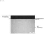
Fig. 5 is a sectional image of a structure of the hard film formed body of Example 1. -
Fig. 6 is a general view showing an electrochemical hydrogen permeation test. -
Figs. 7(a) and 7(b) are views showing an outline of the electrochemical hydrogen permeation test. -
Fig. 8 is a sectional image of a structure of the hard film formed body of Example 3. -
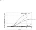
Fig. 9 is a graph showing ionizing currents of Example and Comparative example. -
Figs. 10(a) and 10(b) are graphs showing ionizing currents of Example and Comparative example. - Hereinafter, a hard film formed body according to the present invention is described with reference to the drawings. The hard film formed body of the present invention is used in a machine component or the like, in particular a bearing used in a hydrogen entering environment. The hydrogen entering environment denotes an environment in which or various types of hydrogen such as hydrogen gas or water in a use environment and hydrogen atom in lubricant possibly enters a base material and diffuses.
-
Fig. 1 is a general sectional view of a first embodiment of a hard film formed body according to the present invention. As shown inFig. 1 , a hard film formedbody 1 has abase material 2 and ahard film 3 formed on a surface of thebase material 2. Thehard film 3 has a function that suppresses entering and diffusing of hydrogen atom. For example, thehard film 3 delays the entering of the hydrogen into thebase material 2 and the diffusing of the hydrogen. With this, the hydrogen embrittlement caused in thebase material 2 can be delayed. Thehard film 3 is formed of a material different from that of thebase material 2. - In the present invention, (A) a ratio of the Vickers hardness of the
hard film 3 to the Vickers hardness of the base material 2 (Vickers hardness (Hv) of thehard film 3 / Vickers hardness (Hv) of thebase material 2, hereinafter also simply referred to as a hardness ratio) is 0.90-1.20, or (B) the thickness of thehard film 3 is 0.1 or more and less than 3 µm. With this, the adhesiveness of thehard film 3 to thebase material 2 becomes superior, and thehard film 3 can stably show the hydrogen embrittlement resistance and the wear resistance. In a case in which the feature (A) is fulfilled, the hardness ratio is preferably 0.90-1.10, more preferably 0.95-1.05, further more preferably 0.98-1.02. The hardness ratio may be more than 1.00. - The
base material 2 employs any steel material generally used. Examples of thebase material 2 includes high carbon chromium bearing steel (SUJ1, SUJ2, SUJ3, SUJ4, SUJ5 and the like; JIS G 4805), cement steel (SCr420, SCM420 and the like; JIS G 4053), and stainless steel (SUS440C and the like; JIS G 4303). Thebase material 2 need not necessarily employ a special material or a special heat treatment against the hydrogen embrittlement. - The Vickers hardness of the base material 2 (the Vickers hardness of the surface on which the
hard film 3 is formed) is preferably 500-1,000 Hv, more preferably 600-900 Hv, further more preferably 700-800 Hv. With the Vickers hardness of thebase material 2 within the above-described range, for example, the hardness ratio of (A) can be easily set in the specified range while securing the wear resistance of the hard film formed body. - The
base material 2 may be hardened by a heat treatment before forming thehard film 3. Further, a nitride layer may be formed by a nitriding treatment. An example of the nitriding treatment includes a plasma nitriding treatment that hardly generates an oxide layer that deteriorates the adhesiveness, on the surface of the base material. Further, a pretreatment may be applied to thebase material 2 for improving the adhesiveness of thehard film 3 to thebase material 2. Examples of the pretreatment include a degreasing treatment using a solvent or an alkali solution, and an acid immersing treatment. - The surface roughness Ra of the
base material 2 is, for example, 0.1 µm or less, and preferably 0.05 µm or less. Various machining treatment (a surface finishing treatment and the like) may be performed in order to adjust the surface roughness Ra of thebase material 2. - The hydrogen embrittlement affects a steel material much more as its strength is higher. In particular, delayed fracture is remarkable in the high strength steel having a yield stress of 1 GPa. However, the hard film formed body of the present invention forms the following hard film or a DLC layer on the surface of the steel material so that the delayed fracture due to the hydrogen embrittlement can be favorably suppressed.
- The
hard film 3 may be a coating film that is capable of suppressing the entering and diffusing of the hydrogen atom, and thus examples of thehard film 3 include a Ni coating film containing Ni as a main component, a Cu coating film containing Cu as a main component, a Zn coating film containing Zn as a main component, a WC film, and a combination thereof. Of these coating films, the Ni coating film or the WC film is preferable as thehard film 3 because they can delay the entering and diffusing of hydrogen such as hydrogen gas or water in a use environment and hydrogen atom in lubricant into thebase material 2. Further, the Ni coating film is preferable as thehard film 3 in the configuration that fulfills the above-described feature (A), and the WC film is preferable as thehard film 3 in the configuration that fulfills the above-described feature (B). - Examples of the Ni coating film include a Ni-P coating film, a Ni-B coating film, a Ni-P-B coating film, a Ni-P-B-SiC dispersion coating film, and a combination thereof. These Ni coating films may be formed by a physical vapor deposition (PVD) method such as an ion plating method and a sputtering method, and a plating method such as an electroplating method and an electroless plating method. For example, in the electroless plating method, an electroless plating coating film is formed using a plating bath including various reducers in a nickel salt. In particular, the
hard film 3 is preferably a Ni plating coating film, and the Ni plating coating film preferably includes the Ni-P-B coating film. - The Ni-P-B coating film is a complex coating film of Ni, P and B and is formed by the electroless plating method. In the Ni-P-B coating film, the content of Ni is, for example, 90 mass% or more, preferably 95 mass% or more, and more preferably 97 mass% or more. In the especially preferable composition of the Ni-P-B coating film, the content of Ni is 97 mass% or more, the content of P is 1-3 mass% and the content of B is 1 mass% or less. This composition may be appropriately adjusted based on the characteristics required to the coating film. The Ni-P-B coating film is harder and more superior in the wear resistance than, for example, the Ni-P coating film. An example of the Ni-P-B coating film as a commercially available product includes Kaniboron (product name) produced by JAPAN KANIGEN CO.,LTD.
- In the relation between the heat treatment temperature and the hardness after the plating treatment, the hardness of the Ni-P-B coating film becomes higher as the heat treatment (baking) temperature is higher within a range up to 400°C. This is because the crystallizing of Ni is promoted by the heat treatment. The structure of the Ni-P-B coating film is a fine crystal (polycrystal), and the peak derived from Ni is observed in an X-ray diffraction pattern. Further, the Ni-P-B coating film is harder than the Ni-P coating film. The Ni-P-B coating film shows the Vickers hardness HV of 700 or more in deposition, and the Vickers hardness HV of 800 or more in the heat treatment at the temperature of 200°C.
- In the configuration that fulfills the above-described feature (A), the Vickers hardness of the
hard film 3 is preferably 500-1,000 Hv, more preferably 600-900 Hv, and further more preferably 700-800 Hv. - For example, in a case in which the
hard film 3 includes the Ni-P-B coating film, the hardness of the coating film becomes higher as the heat treatment temperature is higher, while the hardness of thebase material 2 obtained through hardening becomes lower, and thus the strength of the whole of the hard film formed body might be deteriorated. Thus, a steel material hardened by the heat treatment is employed and the Ni-P-B coating film formed on the surface is subjected to the aging treatment at an appropriate temperature, so that the steel material and the hard film with enough strength can be obtained. Accordingly, the hard film formed body with enough strength as a whole can be obtained. Further, even in a case in which the steel material is deformed, it can be prevented that only the hard film is yielded and plastically deformed to cause flaking. The aging treatment need not necessarily be executed depending on the hardness of the steel material. - For example, an influence caused by tempering the
base material 2 can be reduced by setting the baking temperature for the Ni-P-B coating film to 200°C of less, preferably 180°C or less. In this manner, in producing thehard film 3, it is preferable that the tempering temperature for thebase material 2, the required strength of thebase material 2, and the hardness required to thehard film 3 on the surface of thebase material 2 are appropriately selected so as not to cause disadvantages due to the difference between the hardness of thebase material 2 and the hardness of thehard film 3. - In the configuration that fulfills the above-described feature (A), considering the management in producing and a possibility of decreasing of the thickness of the
hard film 3 due to wear, the lower limit of the thickness of thehard film 3 is preferably 1 µm. The upper limit of thehard film 3 is preferably 50 µm in order to suppress the production cost, the processing time, and the imbalance of the stress in the film. The thickness of thehard film 3 is more preferably 3-30 µm, and further more preferably 3-10 µm. The thickness may be set based on the required effect against the hydrogen embrittlement. For example, the thickness of the plating coating film may be adjusted by adjusting the immersing time to the plating bath. - In the configuration that fulfills the above-described feature (B), the WC film may be formed by, for example, the unbalanced magnetron sputtering (UBMS) method using a WC target. The thickness of the WC film is preferably 0.2 µm or more and less than 1 µm. The thickness of the WC film may be 0.2-0.6 µm. The Vickers hardness of the WC film is not especially limited, but may be, for example, 1,000-2,000 Hv. However the Vickers hardness of the WC film may be more than 2,000 Hv.
- The hydrogen diffusion coefficient in the
hard film 3 is preferably 5.00 × 10⁻¹² m2/s or less, may be 1.00 × 10⁻¹² m2/s or less, or 8.00 × 10⁻¹³ m2/s or less. The specific range of the hydrogen diffusion coefficient is, for example, 1.00 × 10⁻¹³ - 8.00 × 10⁻¹³ m2/s. The hydrogen diffusion coefficient is obtained by an electrochemical hydrogen permeation method. The details will be described in Example below. - As one example of the forming method of the
hard film 3, the forming of the Ni-P-B coating film is described. The plating bath including a nickel salt that contains a phosphorus compound and a boron compound as reducing agents is employed. More specifically, examples of the nickel salt include nickel chloride and nickel sulfate, examples of the phosphorus compound include sodium hypophosphite and potassium hypophosphite, and examples of the boron compound include dimethylamino borane and sodium borohydride. The ratio of the nickel salt, the phosphorus compound and the boron compound in the plating bath is appropriately adjusted based on the composition of the plating coating film to be obtained. Further, organic acid such as acetic acid or a chelating agent such as ethylenediaminetetraacetic acid (EDTA) may be added into the plating bath. - pH of the plating bath is preferably 6-7 from a viewpoint of stability and a deposition speed. Further, the temperature of the plating bath is, for example, 60-90°C, and preferably 70-90°C.
- The obtained plating coating film is subjected to the heat treatment (baking) to improve the hardness of the film. The heat treatment temperature is, for example, 100-200°C, preferably 100-180°C, and more preferably 120-160°C. The heat treatment time is, for example, 30-120 minutes. The heat treatment is performed in atmosphere with air, inert gas, or reducing gas.
- As the property of the hard film formed
body 1, in the electrochemical hydrogen permeation method using a specimen formed of the hard film formed body (the thickness of thebase material 2 of 1 mm), when each area of the specimen that is in contact with an electrolytic solution in each of an anode bath and a cathode bath is set to 3.14 cm2 and the electrolysis is performed as the current density at a side of the anode bath of 1 mA/cm2, the extension time of the Breakthrough time of the specimen is preferably 0.4 times or more, more preferably 1.0 time or more, further more preferably 2.0 times or more, 5.0 times or more, or 10.0 times or more as long as the breakthrough time of the target piece formed of thebase material 2 having the thickness of 1 mm. The details of the electrochemical hydrogen permeation method will be described in Example. Second embodiment -
Fig. 2 is a general sectional view showing a second embodiment of a hard film formed body according to the present invention. As shown inFig. 2 , a hard film formedbody 4 includes abase material 5, ahard film 6 formed on a surface of thebase material 5, anintermediate layer 7 formed on thehard film 6, and aDLC layer 8 formed on theintermediate layer 7. In this case, the coating film formed on thebase material 5 has a substantially three-layer structure. The structures of thebase material 5 and thehard film 6 are similar to those of thebase material 2 and thehard film 3 described in the first embodiment (especially, the configuration that fulfills the above-described feature (A)), and thus the description thereof is omitted. - The
intermediate layer 7 is intervened between thehard film 6 and theDLC layer 8. Examples of theintermediate layer 7 include a tungsten carbide (WC) layer, and a mixed layer mainly containing WC and DLC. The WC has an intermediate hardness and an intermediate elastic modulus between thehard film 6 and theDLC layer 8, and thus the concentration of the residual stress after forming the film is hardly caused. - The
intermediate layer 7 is preferably a mixed layer mainly containing the WC and the DLC, and further preferably a layer in which the content rate of the WC in the intermediate layer is continuously or stepwise decreased and the content of the DLC in the intermediate layer is continuously or stepwise increased, toward the side of theDLC layer 8 from the side of thehard film 6. With this, superior adhesiveness can be realized on both surfaces at the side of thehard film 6 and the side of theDLC layer 8. Further, the intermediate layer has a structure in which the WC and the DLC are physically bonded to each other, so that the break in the intermediate layer can be prevented. Further, since the content rate of the DLC is higher at the side of theDLC layer 8, superior adhesiveness can be realized between theDLC layer 8 and theintermediate layer 7. In this case, theintermediate layer 7 bonds the DLC, which has a non-adhesive property, to thehard film 6 by the WC using an anchor effect. - The
DLC layer 8 mainly contains the DLC. The DLC is a structure of a combination of a graphite structure (sp2) and a diamond structure (sp3), which is an intermediate structure between the graphite structure and the diamond structure. Examples of the forming method of theDLC layer 8 include a physical vapor deposition method such as a sputtering method and an ion plating method, a chemical vapor deposition method, and the UBMS method. - The
DLC layer 8 preferably includes a relaxing layer potion (not shown) at an adjacent side of theintermediate layer 7. The relaxing layer portion is formed by continuously or stepwise changing at least one of film forming condition parameters (an introduction amount of hydrogencarbonate-based gas, a vacuum degree, a bias voltage) in the UBMS method in order to avoid rapid change of the parameters in a case in which, for example, the parameters are different between theintermediate layer 7 and theDLC layer 8. More specifically, each parameter is continuously or stepwise changed within a range between a start point as the film forming condition parameter for forming the uppermost layer of theintermediate layer 7 and an end point as the film forming condition parameter for forming theDLC layer 8. With this, the rapid change of the properties (hardness, elastic modulus, etc.) between theintermediate layer 7 and theDLC layer 8 is not caused, and thus superior adhesiveness between theintermediate layer 7 and theDLC layer 8 can be realized. For example, when the bias voltage is continuously or stepwise increased, the composition ratio of the graphite structure (sp2) and the diamond structure (sp3) in the DLC structure becomes close to the diamond structure (sp3), to be the gradient hardness (the hardness is increased). - In the hard film formed
body 4 of the second embodiment, the Vickers hardness of theDLC layer 8, which is a surface layer, is, for example, 1,000-3,000 Hv. - The total film thickness of the
intermediate layer 7 and theDLC layer 8 is preferably 1.0-5.0 µm, and more preferably 1.0-3.0 µm. With the total film thickness within the above-described range, the wear resistance and the mechanical strength can be improved and the flaking of theintermediate layer 7 and theDLC layer 8 can be suppressed. Further, the total film thickness of theintermediate layer 7 and theDLC layer 8 is preferably smaller than the film thickness of thehard film 6. In the hard film formedbody 4, the total thickness of the coating film formed on thebase material 5 is preferably 3.0-30 µm, and more preferably 3.0-10 µm. - As one example of the forming method for the
intermediate layer 7 and theDLC layer 8, a method using a UBMS device using Ar gas as sputtering gas is described. - For example, in a case in which the
intermediate layer 7 is a mixed layer mainly containing the WC and the DLC, a film is formed while continuously or stepwise increasing the sputtering electric power applied to a graphite target as a carbon supply source and decreasing the electric power applied to a WC target, so that a layer is formed having a gradient composition in which the content rate of the WC is decreased and the content rate of the DLC is increased toward theDLC layer 8. The degree of vacuum in the UBMS device (the film forming chamber) in forming theintermediate layer 7 is, for example, 0.2-1.2 Pa. The bias voltage applied to the base material is, for example, 20-100 V. - The
DLC layer 8 is formed by depositing the carbon atoms supplied from the carbon supply source, on theintermediate layer 7 as both the graphite target and the hydrogencarbonate-based gas (methane gas, acetylene gas, benzene, etc.), which are the carbon supply sources, are used together and the rate of the introduction amount of the hydrogencarbonate-based gas is set to, for example, 1-15 relative to 100 of the introduction amount of the Ar gas. The degree of vacuum in the device is, for example, 0.2-0.9 Pa. - In the example shown in
Fig. 2 , theintermediate layer 7 is intervened between thehard film 6 and theDLC layer 8, however theintermediate layer 7 may be omitted. Further, the hard film formed body of the present invention is not limited to the examples shown inFigs. 1 and2 . For example, theintermediate layer 7 and theDLC layer 8 may be repeatedly laminated on thehard film 6. Further, the DLC layer may be formed on the surface of the hard film that fulfills the above-described feature (B) in the first embodiment. In this case, the hard film formed body has, for example, a base material, a WC film formed on a surface of the base material, and a DLC layer formed on the WC film. - The usage of the hard film formed body of the present invention is not especially limited, but may be preferably applied to a machine component because of its superior mechanical properties. The machine component is used in a rolling portion or a sliding portion of a device. Specific examples of the machine component include a sliding component, a bearing component, a roll material for rolling, a compressor vane, an engine component such as a gas turbine vane, a cutting tool (cutting tip), and a gear. Examples of the bearing component include a raceway ring such as an inner ring and an outer ring, a bearing rolling element, and a cage. The bearing of the present invention employs the hard film formed body of the present invention in the bearing component. Examples of the bearing include a rolling bearing, a sliding bearing (a spherical bushing), a linear guide bearing, a ball bearing, and a linear bearing.
- One example of a bearing of the present invention is described with reference to
Fig. 3. Fig. 3 is a sectional view of a deep groove ball bearing using the hard film formed body of the first embodiment as a rolling element. A deep groove ball bearing 11 includes aninner ring 12 having an inner ring raceway surface 12a on an outer peripheral surface, anouter ring 13 having an outerring raceway surface 13a on an inner peripheral surface, and a plurality of balls (rolling elements) 14 rolling between the inner ring raceway surface 12a and the outerring raceway surface 13a. Theballs 14 are retained by acage 15 at the same intervals. Both end openings in an axial direction of the inner and outer rings are sealed byseal members 16, andgrease 17 is filled in a bearing space. - In the rolling bearing shown in
Fig. 3 , ahard film 18 is formed on the whole spherical surface of theball 14. In the example shown inFig. 3 , thehard film 18 is formed only on theball 14, but may be formed on a surface (a portion) of other bearing component such as theinner ring 12 and theouter ring 13 depending on the type of the bearing and its usage. In a configuration in which two or more components come into contact with or slide to each other, it is preferable that the hard film formed body is used in at least one of them. - The bearing of the present invention can favorably suppress the early flaking due to the hydrogen embrittlement when used in a hydrogen entering environment because at least a portion of the bearing component is formed of the hard film formed body of the present invention. Thus, the bearing of the present invention is favorable as a bearing used in an environment in which the early flaking due to the hydrogen embrittlement is easily caused.
- For example, the bearing of the present invention is used as a bearing for a transaxle of vehicles (fuel cell vehicle (FCV), electric vehicle (EV), etc.), a transmission of vehicles (continuously variable transmission, etc.), and a vehicle motor (for a driving device or a transmission). The bearing of these usages are required to be endurable against a rapid change of the rotation speed in accordance with gear shift, a high rotation, or a high load. Further, in these devices, lubrication oil with low viscosity is used to reduce power loss. In such a severe use environment, wear of the raceway ring or the rolling element is promoted by sliding. When a steel newly surface is generated by the wear, water or a component of the lubricant is decomposed to generate hydrogen and the hydrogen enters the steel, so that the early flaking due to the hydrogen embrittlement is easily caused. Further, in the fuel cell vehicle, hydrogen leaked from hydrogen equipment might promote the hydrogen embrittlement of the rolling bearing.
- Further, the bearing of the present invention is used as a bearing for hydrogen usable devices. In particular, the bearing of the present invention is favorable as a bearing used in an environment exposed to hydrogen supplied from an outside. It is expected that a case is increased that the bearing is used in a hydrogen atmosphere (including a mixed atmosphere with which hydrogen is mixed) due to the increase of the use of hydrogen in future. In such a case, it is considered that not only hydrogen caused by the decomposition of the grease (hydrogen of internal factor) but also hydrogen supplied from the outside (hydrogen of external factor) affects the early flaking due to the hydrogen embrittlement. The bearing of the present invention employs the hard film formed body to effectively suppress the early flaking even in a case in which the early flaking due to the hydrogen embrittlement is concerned compared to the conventional case.
- Examples of the hydrogen usable device include a ball valve and a compressor for hydrogen stations. The type of the compressor is not especially limited, but may be a reciprocating (reciprocation) type, a rotation (screw) type, a centrifugal type, or an axial flow type. Further, the hydrogen usable device also includes a high-pressure-hydrogen pressure reducing valve or a hydrogen circulating pump for the above-described fuel cell vehicles.
-
Fig. 4 shows a sectional view of a hydrogen circulating pump to which the bearing of the present invention is applied. Ahydrogen circulating pump 21 includes amotor housing 22, apump housing 23,rotational shafts motor stator 26, amotor rotor 27, gears 28, 29,rotors bearings - The
motor housing 22 is mounted to thepump housing 23. One end portion of therotational shaft 24 is disposed in themotor housing 22, and the other end portion of therotational shaft 24 is disposed in thepump housing 23. The one end portion of therotational shaft 24 is rotatably supported by the rollingbearing 32 disposed in themotor housing 22, and the other end portion of therotational shaft 24 is rotatably supported by the rollingbearing 33 disposed in thepump housing 23. Therotational shaft 24 is rotatably supported by the rollingbearings pump housing 23, at a portion between the one end portion and the other end portion. - The
rotational shaft 25 is disposed in thepump housing 23. One end portion of therotational shaft 25 is rotatably supported by the rollingbearing 36 disposed in thepump housing 23. Therotational shaft 25 is rotatably supported by the rollingbearing 37 disposed in thepump housing 23, at a portion separate from the one end portion. - The
motor stator 26 is disposed in themotor housing 22. Themotor rotor 27 is mounted to therotational shaft 24 to face themotor stator 26. Therotational shaft 24 is rotated by themotor stator 26 and themotor rotor 27. Thegear 28 is mounted to therotational shaft 24. Thegear 29 is mounted to therotational shaft 25. A rotation of therotational shaft 24 is transmitted to therotational shaft 25 via thegears gear 28 is disposed between the rollingbearing 34 and the rollingbearing 35. Thegear 29 is disposed between the rollingbearing 36 and the rollingbearing 37. - A pump chamber 23a is formed in the
pump housing 23. Therotors rotor 30 is mounted to therotational shaft 24. Therotor 31 is mounted to therotational shaft 25. When therotor 30 is rotated in accordance with the rotation of therotational shaft 24 and therotor 31 is rotated in accordance with the rotation of therotational shaft 25, hydrogen is sucked into the pump chamber 23a and the hydrogen is discharged from the pump chamber 23a. - In the example shown in
Fig. 4 , each of the rollingbearings bearing 33 is used in an environment exposed to hydrogen supplied from the outside (for example, hydrogen atmosphere) . Each of the rollingbearings Fig. 4 , at least one of the rollingbearings - The present invention is further specifically described with reference to Examples and Comparative examples, however the present invention is not limited to Examples and Comparative examples.
- SUJ2 having the thickness of approximately 1 mm is hardened and then tempered at 190°C so that a steel plate having the hardness of 61.5 HRC (730 Hv) is prepared. In each of Examples 1 and 2, a Kaniboron plating treatment, which is one kind of the electroless plating methods, is subjected to the surface of the steel plate. The composition of the obtained coating film includes Ni of 97-98 mass%, P of 1.5-2.5 mass%, and B of 0.05-0.5 mass%. After the Kaniboron plating treatment, the aging hardening is performed by the baking at 150°C for one hour, so as to form the electroless Ni-P-B plating coating film as the hard film. The thickness of the Ni plating coating film is 5 µm (Example 1) or 30 µm (Example 2) .
Fig. 5 shows a sectional image of a structure of the hard film formed body of Example 1. Technically, the Ni plating coating film has a structure in which the electroless Ni-P plating coating film is formed on the base material and the electroless Ni-P-B plating coating film is formed thereon (the uppermost surface side). In Comparative example 1, the steel plate of SUJ2 is employed to which the hardening and the tempering are performed while the above-described plating treatment is not performed. - The Vickers hardness of the hard film of each of the specimens of Examples 1 and 2 is measured based on JIS Z 2244. According to the measurement, the hardness of the hard film of Example 1 is 724 Hv, and the hardness of the hard film of Example 2 is 735 Hv. These are substantially the same as the hardness of SUJ2 (the base material). A ratio of the Vickers hardness of the hard film to the Vickers hardness of the base material is shown in Table 1. The yield stress of the base material is approximately 1,200-1,700 MPa.
Table 1 Coating film structure Hardness of base material Hardness of hard film Hardness ratio Comparative example 1 SUJ2 730 Hv - - Example 1 SUJ2 + Ni plating coating film of 5 µm 730 Hv 724 Hv 0.99 Example 2 SUJ2 + Ni plating coating film of 30 µm 730 Hv 735 Hv 1.01 - The electrochemical hydrogen permeation is executed to evaluate hydrogen that enters and diffuses in each of the specimens of Examples 1 and 2 and Comparative example 1.
Fig. 6 is a general view showing a test device. As shown inFig. 6 , a test device 41 includes acathode bath 42, ananode bath 45, a cathode electrode 44 (for example, Pt electrode), an anode electrode 47 (for example, Pt electrode), a galvanostat and a potentiostat. Thecathode bath 42 and theanode bath 45 are separated by aspecimen 51. In Examples 1 and 2, the hard film formed on thespecimen 51 is disposed at the side of thecathode bath 42. - An
electrolytic solution 43 is accommodated in thecathode bath 42 and thecathode electrode 44 is immersed therein. Anelectrolytic solution 46 is accommodated in theanode bath 45 and theanode electrode 47 is immersed therein. In this test, theelectrolytic solution 43 employs a solution of 0.1N sulfuric acid with thiourea added thereto, and theelectrolytic solution 46 employs 1N sodium hydroxide. The galvanostat is connected to thecathode electrode 44 and thespecimen 51. The potentiostat is connected to theanode electrode 47, thespecimen 51, and a reference electrode 49 (for example, Ag/AgCl electrode) . Thereference electrode 49 is immersed into a KCl saturatedsolution 48 and is connected to theanode bath 45 via asalt bridge 50. - In the test device 41, a specified electric potential is applied to a portion between the
specimen 51 and thecathode electrode 44 by the galvanostat to perform electrolysis, so that hydrogen is generated on the surface of thespecimen 51 at the side of thecathode bath 42. The generated hydrogen enters thespecimen 51 from the surface of thespecimen 51 at the side of thecathode bath 42. The potentiostat keeps the surface potential of thespecimen 51 at the electric potential that oxidizes a hydrogen atom to a hydrogen ion. Thus, the hydrogen atom that enters and diffuses in the specimen from thecathode bath 42 and reaches the surface of thespecimen 51 at the side of theanode bath 45 is immediately oxidized to the hydrogen ion, so that ionizing current is generated. In this test, the Breakthrough time method that calculates the diffusion coefficient based on the time until an increase of the ionizing current starts. Specifically, as the time (Breakthrough time) until the increase of the ionizing current starts from the beginning of the test is set to tb and the thickness of the specimen 51 (the total thickness of the base material and the hard film) is set to L, the diffusion coefficient DH is calculated from the following formula (1) (reference document: Takahiro Kushida, Research on hydrogen embrittlement by electrochemical hydrogen permeation technique, Zairyo-to-Kankyo, 2000, vol. 49, p. 195-200). The measurement of the diffusion coefficient is performed at 20-25°C.
Math 1
- Specifically, as each of areas of the
specimen 51 that are in contact with theelectrolytic solution cathode bath 42 and theanode bath 45, respectively, is set to 3.14 cm2, the electrolysis is performed at the current density at the side of theanode bath 45 of 1 mA/cm2. The ionizing current of the cathode side is measured at each 0.1 µA so as to determine the increase of the ionizing current. The average of the Breakthrough time and the average of the diffusion coefficient DH of each of Examples 1 and 2 and Comparative example 1 are shown in Table 2.Table 2 Coating film structure Test number Average ± 2σ of Breakthrough time (s) Average ± 2σ of diffusion coefficient DH (× 10-11 m2/s) Comparative example 1 SUJ2 4 2,155 ± 559 3.16 ± 0.86 Example 1 SUJ2 + Ni plating coating film of 5 µm 3 3,041 ± 177 2.37 ± 0.10 Example 2 SUJ2 + Ni plating coating film of 30 µm 3 7,958 ± 179 0.99 ± 0.03 - As shown in Table 2, Examples 1 and 2 each including the Ni plating coating film increase in thickness merely by approximately 0.5% and 3%, respectively, compared to Comparative example 1 (SUJ2 having the thickness of 1 mm), while the Breakthrough time thereof are extended by 41% and 269%, respectively. Further, the diffusion coefficient DH calculated by the Breakthrough time method of Examples 1 and 2 are 75% and 31%, respectively, relative to that of Comparative example 1. Accordingly, the hydrogen is prevented from entering and diffusing by the Ni plating coating film.
- Further, the deviation (2σ) of the Breakthrough time of Comparative example 1 is the largest, which is approximately ± 26%. Against this, the deviations of the Breakthrough time of Examples 1 and 2 are ± 6% and ± 2%, respectively. In t-test, there is a significant difference between the Breakthrough time of Comparative example 1 and the Breakthrough time of Examples 1 and 2 by the significance level of 1%, and there is a significant difference between the diffusion coefficients DH calculated by the Breakthrough times by the significance level of 5%.
- The Breakthrough time of each of Examples 1 and 2 and Comparative example 1 is a benchmark as to the time until the hydrogen atom diffuses in a portion at the depth of 1 mm from the surface of the hard film formed body.
- The hydrogen diffusion coefficient of the Ni plating coating film is presumed by the finite element method using the hydrogen diffusion coefficient of 3.16 × 10⁻¹¹ m2/s and the Breakthrough time of Comparative example 1 and the Breakthrough times of Examples 1 and 2 obtained by the above-described electrochemical hydrogen permeation method. As a result, the hydrogen diffusion coefficient of the Ni plating coating film of Example 1 is 4.95 × 10⁻¹³ m2/s, and the hydrogen diffusion coefficient of the Ni plating coating film of Example 2 is 2.84 × 10⁻¹³ m2/s. Technically, both the hydrogen diffusion coefficients are identical to each other, however there is a difference because of a measurement error or a deviation of the film thickness. The presuming of the hydrogen diffusion coefficient by the finite element method is as below.
- (1) As a concentration of the hydrogen at one side of a plate having the thickness of 1 mm is set to 1, the concentration of the hydrogen that diffuses the other side of the plate after the Breakthrough time passes is analyzed (this concentration is presumed as a detection lower limit concentration).
- (2) As the concentration of the hydrogen at one side of the plate is set to 1 and the hydrogen diffusion coefficient of Comparative example 1 is applied to SUJ2, the analysis is repeated by appropriately changing the hydrogen diffusion coefficient of the coating film as an unknown quantity until the concentration of the hydrogen diffuses the other side of the plate after the Breakthrough time of Comparative example 1 passes becomes equal to the concentration of the hydrogen calculated in the above-described (1).
- In the above-described electrochemical hydrogen permeation test, the thiourea is added to the electrolytic solution at the cathode side. Thus, as shown in
Fig. 7(a) , it is expected that Had is preferentially consumed in an entering reaction of Had → Hab by a mechanism that prevents the hydrogen atoms (Had) that are stuck to the surface from being recombined to become H2. Further, it is presumed that the hydrogen atom follows the reaction path after H2ad when there are excessive Had. Meanwhile, in a case in which the hydrogen is caused to enter the specimen using the hydrogen gas or a strength test such as a fatigue test is executed, the entering and diffusing of the hydrogen is delayed or the strength deterioration due to the hydrogen embrittlement can be prevented also by suppressing a dissociative adsorption reaction of the hydrogen molecule (H2 ⇔ H2ad or H2ad ⇔ 2Had) (seeFig. 7 (b) ) . However, in such a case, when the supply source of the hydrogen is not the hydrogen molecule but the hydrogen atom or the hydrogen ion in any molecule, the effect as the hydrogen embrittlement measure might not be shown. Thus, in order to handle various hydrogen supply sources such as the hydrogen atom in water in the use environment and the hydrogen atom in the lubrication oil in addition to the hydrogen gas, in this example, the electrochemical hydrogen permeation test is executed that focuses on the entering and diffusing of the hydrogen. - Similar to Example 1, the Kaniboron plating treatment is applied to the surface of the steel plate that has been subjected to the hardening and tempering, so as to form the Ni plating coating film having the thickness of 5 µm. Further, the WC/DLC coating film as an intermediate layer is formed on the Ni plating coating film, and the DLC coating film is formed on the uppermost surface.
- The WC/DLC coating film is formed by the UBMS method. Specifically, the sputtering voltage applied to the WC target and the graphite target is adjusted while supplying methane gas, which is hydrogencarbonate-based gas, so that the composition ratio of the WC and the DLC is inclined to form the WC/DLC gradient layer in which the WC is much at the side of the Ni plating coating film and the DLC is much at the side of the surface. Further, the DLC coating film is also formed by the UBMS method. In this case, the graphite target and the methane gas, which is hydrogencarbonate-based gas, are employed as the carbon supply source.
Fig. 8 shows a sectional image of a structure of the hard film formed body of Example 3. - Next, the electrochemical hydrogen permeation test is executed on the specimen of Example 3. Here, in the electrochemical hydrogen permeation test, it is necessary to apply the current on the surface of the specimen and to measure the current. However, the specimen of Example 3 has the DLC coating film, which has extreme high electric resistance, on the surface at the side of the cathode bath that generates the hydrogen to enter the specimen, and thus it is difficult to execute the electrochemical hydrogen permeation test unlike the above-described Example. Thus, the electrochemical hydrogen permeation test is executed after forming a gold vapor deposition film of approximately several nanometers on the DLC coating film to decrease the electric resistance of the uppermost surface. In order to check the capability of preventing the hydrogen permeation of the gold vapor deposition film, the specimen (Comparative example 2) that has the gold vapor deposition film, which is the same as Example 3, on the surface of SUJ2 is employed as the comparative target. The test condition is similar to that of Examples 1 and 2 and Comparative example 1. The result is shown in Table 3.
Table 3 Coating film structure 1) Test number Average ± 2σ of Breakthrough time (s) Average ± 2σ of diffusion coefficient DH (× 10-11 m2/s) Comparative example 2 SUJ2 2 2,286 ± 66 2.91 ± 0.14 Example 3 SUJ2 + Ni plating coating film of 5 µm + (WC/DLC coating film + DLC coating film) of 2 µm 2 810, 650 ± 265,692 0.00882 ± 0.00290 1) the gold vapor deposition film of several nanometers is formed on the uppermost surface of each specimen in order for the measurement in the electrochemical hydrogen permeation test - Comparing Comparative example 2 in Table 3 and Comparative example 1 in Table 2, it is found that the capability of preventing the hydrogen permeation of the gold vapor deposition film is small. As shown in Table 3, Example 3 having the Ni plating coating film, the WC/DLC coating film, and the DLC coating film largely extends the Breakthrough time and largely decreases the diffusion coefficient DH, compared to Comparative example 2. The hydrogen diffusion coefficient of each of the WC/DLC coating film and the DLC coating film is presumed as 1.00 × 10⁻¹⁵ - 1.00 × 10⁻¹⁴ m2/s (specifically, approximately 1.18 × 10⁻¹⁵ m2/s), which is smaller than the hydrogen diffusion coefficient of the Ni plating coating film.
- Comparing the result of Example 3 and the results of Examples 1 and 2, the advantageous effect of Example 3 is remarkable. It is found that each of the WC/DLC coating film and the DLC coating film prevents the hydrogen from entering and diffusing, and when the WC/DLC coating film and the DLC coating film are formed on the Ni plating coating film, the effect of the Ni plating coating film is remarkably improved.
-
Fig. 9 is a graph summarizing the results of Examples 1 to 3 and Comparative examples 1 and 2. As shown inFig. 9 , the hydrogen embrittlement delaying effect can be shown by forming the Ni plating coating film as the hard film, on the surface of the base material. - The WC film having the thickness of 0.4 µm is formed by the unbalanced magnetron sputtering (UBMS) method, on the surface of SUJ2 (730 Hv) having the thickness of 1 mm, which is Comparative example 1, that has been subjected to the hardening and tempering. The Vickers hardness of the WC film is 1,000-2,000 Hv.
- The electrochemical hydrogen permeation test is executed on the obtained specimen of Example 4. The test condition is similar to that of Examples 1 and 2 and Comparative example 1. The result is shown in Table 4 and
Fig. 10 .Table 4 Coating film structure Test number Average of Breakthrough time (s) Average of diffusion coefficient DH (× 10-11 m2/s) Comparative example 1 SUJ2 4 2,155 3.16 Example 4 SUJ2 + WC film of approximately 0.4 µm 2 19,925 0.374 - As shown in Table 4 and
Fig. 10 , Example 4 having the WC film largely extends the Breakthrough time and largely decreases the diffusion coefficient DH, compared to Comparative example 1. The hydrogen diffusion coefficient of the WC film is analyzed by the finite element method (FEM) based on the average shown in Table 4 and is presumed as 3.37 × 10⁻¹² m2/s. Comparing the result of the WC film of Example 4 and the results of the Ni plating coating films of Examples 1 and 2, the advantageous effect of Example 4 is remarkable. In this manner, the hydrogen embrittlement delaying effect can be favorably shown also by forming the WC film as the hard film, on the surface of the base material. - The hard film formed body of the present invention improves the hydrogen embrittlement resistance and the wear resistance and has superior flaking resistance, so that the hard film formed body can be favorably used in a machine component such as a bearing that is used in a hydrogen entering environment.
-
- 1:
- hard film formed body
- 2:
- base material
- 3:
- hard film
- 4:
- hard film formed body
- 5:
- base material
- 6:
- hard film
- 7:
- intermediate layer
- 8:
- DLC layer
- 11:
- deep groove ball bearing (bearing)
- 12:
- inner ring
- 13:
- outer ring
- 14:
- ball (rolling element)
- 15:
- cage
- 16:
- seal member
- 17:
- grease
- 18:
- hard film
- 21:
- hydrogen circulating pump
- 22:
- motor housing
- 23:
- pump housing
- 24, 25:
- rotational shaft
- 26:
- motor stator
- 27:
- motor rotor
- 28, 29:
- gear
- 30, 31:
- rotor
- 32, 33, 34, 35, 36, 37:
- rolling bearing
- 41:
- test device
- 42:
- cathode bath
- 43:
- electrolytic solution
- 44:
- cathode electrode
- 45:
- anode bath
- 46:
- electrolytic solution
- 47:
- anode electrode
- 48:
- KCl saturated solution
- 49:
- reference electrode
- 50:
- salt bridge
- 51:
- specimen
Claims (12)
- A hard film formed body comprising: a base material, and a hard film that suppresses entering and diffusing of a hydrogen atom, the hard film being formed on a surface of the base material,
wherein:(A) a ratio of the Vickers hardness of the hard film to the Vickers hardness of the base material is 0.90-1.20, or(B) the thickness of the hard film is 0.1 µm or more and less than 3 µm. - The hard film formed body as defined in claim 1, that fulfills the feature (A), wherein the Vickers hardness of each of the base material and the hard film is 500-1,000 Hv.
- The hard film formed body as defined in claim 1, that fulfills the feature (A), wherein the hard film that suppresses the entering and diffusing of the hydrogen atom is a Ni coating film.
- The hard film formed body as defined in claim 3, wherein the Ni coating film includes a Ni-P-B coating film that contains Ni by 90 mass% or more.
- The hard film formed body as defined in claim 1, wherein:in the electrochemical hydrogen permeation method using a specimen formed of the hard film formed body (the thickness of the base material is 1 mm),as each of areas of the specimen that are in contact with electrolytic solutions in a cathode bath and an anode bath, respectively, is set to 3.14 cm2 and the electrolysis is performed at a current density at the side of the anode bath of 1 mA/cm2,the extension time of the Breakthrough time of the specimen is 0.4 times or more as long as the Breakthrough time of a target formed of the base material having the thickness of 1 mm.
- The hard film formed body as defined in claim 1, that fulfills the feature (A), wherein an intermediate layer and a diamond-like carbon layer are formed on the surface of the hard film.
- The hard film formed body as defined in claim 1, that fulfills the feature (A), wherein:the ratio of the Vickers hardness is 0.95-1.05,the Vickers hardness of each of the base material and the hard film is 700-800 Hv,the hard film that suppresses the entering and diffusing of the hydrogen atom is a Ni coating film,the Ni coating film includes a Ni-P-B coating film that contains Ni by 90 mass% or more, andan intermediate layer and a diamond-like carbon layer are formed on the surface of the hard film.
- The hard film formed body as defined in claim 1, that fulfills the feature (B), wherein the hard film that suppresses the entering and diffusing of the hydrogen atom is a tungsten carbide film.
- The hard film formed body as defined in claim 8, wherein the thickness of the tungsten carbide film is 0.2 µm or more and less than 1 µm.
- A machine component using the hard film formed body as defined in claim 1.
- The machine component as defined in claim 10, formed as a bearing member.
- A bearing using the bearing member as defined in claim 11.
Applications Claiming Priority (3)
| Application Number | Priority Date | Filing Date | Title |
|---|---|---|---|
| JP2022082651 | 2022-05-19 | ||
| JP2023079728A JP2023171300A (en) | 2022-05-19 | 2023-05-12 | Hard film formations, mechanical parts, and bearings |
| PCT/JP2023/018229 WO2023224026A1 (en) | 2022-05-19 | 2023-05-16 | Rigid-film-coated object, machine component, and bearing |
Publications (2)
| Publication Number | Publication Date |
|---|---|
| EP4527979A1 true EP4527979A1 (en) | 2025-03-26 |
| EP4527979A4 EP4527979A4 (en) | 2026-05-06 |
Family
ID=88835543
Family Applications (1)
| Application Number | Title | Priority Date | Filing Date |
|---|---|---|---|
| EP23807628.5A Pending EP4527979A4 (en) | 2022-05-19 | 2023-05-16 | Object, machine component and bearing coated with a rigid film |
Country Status (3)
| Country | Link |
|---|---|
| EP (1) | EP4527979A4 (en) |
| CN (1) | CN119213169A (en) |
| WO (1) | WO2023224026A1 (en) |
Family Cites Families (9)
| Publication number | Priority date | Publication date | Assignee | Title |
|---|---|---|---|---|
| JP3486805B2 (en) * | 1998-06-03 | 2004-01-13 | 三菱電機株式会社 | Sliding contact member, opening / closing operation device using the same, and circuit breaker using the same |
| JP2003156053A (en) * | 2001-11-22 | 2003-05-30 | Koyo Seiko Co Ltd | Swivel bearing |
| JP2005069273A (en) | 2003-08-28 | 2005-03-17 | Nsk Ltd | Rolling bearing |
| JP4764104B2 (en) * | 2005-08-24 | 2011-08-31 | シチズンホールディングス株式会社 | Decorative product and manufacturing method thereof |
| JP5224969B2 (en) | 2008-08-12 | 2013-07-03 | 山陽特殊製鋼株式会社 | Rolling parts with long life in a hydrogen environment |
| JP2010174360A (en) | 2009-02-02 | 2010-08-12 | Hitachi Ltd | Hydrogen embrittlement resistant material, and method for producing the same |
| US9347491B2 (en) * | 2011-09-22 | 2016-05-24 | Ntn Corporation | Hard film, hard film formed body, and rolling bearing |
| JP2015036518A (en) * | 2013-08-12 | 2015-02-23 | 株式会社東芝 | Steam turbine component and method of manufacturing the same |
| JP2020152982A (en) * | 2019-03-22 | 2020-09-24 | アイシン精機株式会社 | Ni-P-B-based plating film and sliding member having the film |
-
2023
- 2023-05-16 CN CN202380041019.8A patent/CN119213169A/en active Pending
- 2023-05-16 EP EP23807628.5A patent/EP4527979A4/en active Pending
- 2023-05-16 WO PCT/JP2023/018229 patent/WO2023224026A1/en not_active Ceased
Also Published As
| Publication number | Publication date |
|---|---|
| CN119213169A (en) | 2024-12-27 |
| WO2023224026A1 (en) | 2023-11-23 |
| EP4527979A4 (en) | 2026-05-06 |
Similar Documents
| Publication | Publication Date | Title |
|---|---|---|
| US6828041B2 (en) | Rolling apparatus | |
| EP1262674B1 (en) | Rolling sliding member and rolling apparatus | |
| EP2103711A1 (en) | Highly corrosion-resistant members and processes for production thereof | |
| EP2759620B1 (en) | Hard film, hard film formed body, and rolling bearing | |
| US20080277031A1 (en) | Surface-carbonitrided stainless steel part excellent in wear resistance and its manufacturing method | |
| JPWO2002008623A1 (en) | Rolling Device | |
| WO2001069100A1 (en) | Rolling support device and method for manufacturing the same | |
| EP3845769B1 (en) | Double-row self-aligning roller bearing and main shaft support device for wind generation equipped with same | |
| JP5746832B2 (en) | Stainless steel screws | |
| US8172561B2 (en) | Metal part and method of manufacturing metal part | |
| JP2007297676A (en) | Shaft manufacturing method and shaft obtained by this method | |
| JP2010180468A (en) | Rolling bearing | |
| WO2023224026A1 (en) | Rigid-film-coated object, machine component, and bearing | |
| JP2023171300A (en) | Hard film formations, mechanical parts, and bearings | |
| JP2025082765A (en) | Hard film forming body, mechanical component, and bearing | |
| JP2010222648A (en) | Carbon steel material manufacturing method and carbon steel material | |
| JP2019056141A (en) | Carbonitriding steel and carbonitriding bearing parts | |
| JP2007291466A (en) | Metal surface treatment method, rolling sliding member and rolling device | |
| JP2004003627A (en) | Shaft, planetary gear unit, and cam follower | |
| US20070183703A1 (en) | Rolling bearing having a nickel-phosphorus coating | |
| JP2007284760A (en) | Sliding member | |
| JP2004169848A (en) | Rolling device | |
| Lu et al. | Characteristic evaluation of friction and wear in the CN and TiN coated gear | |
| WO2008143589A1 (en) | Refrigerant compressor sliding surface with non-integral reaction layer | |
| JPS6345479A (en) | Swash plate type compressor |
Legal Events
| Date | Code | Title | Description |
|---|---|---|---|
| STAA | Information on the status of an ep patent application or granted ep patent |
Free format text: STATUS: THE INTERNATIONAL PUBLICATION HAS BEEN MADE |
|
| PUAI | Public reference made under article 153(3) epc to a published international application that has entered the european phase |
Free format text: ORIGINAL CODE: 0009012 |
|
| STAA | Information on the status of an ep patent application or granted ep patent |
Free format text: STATUS: REQUEST FOR EXAMINATION WAS MADE |
|
| 17P | Request for examination filed |
Effective date: 20241203 |
|
| AK | Designated contracting states |
Kind code of ref document: A1 Designated state(s): AL AT BE BG CH CY CZ DE DK EE ES FI FR GB GR HR HU IE IS IT LI LT LU LV MC ME MK MT NL NO PL PT RO RS SE SI SK SM TR |
|
| DAV | Request for validation of the european patent (deleted) | ||
| DAX | Request for extension of the european patent (deleted) | ||
| A4 | Supplementary search report drawn up and despatched |
Effective date: 20260410 |
|
| RIC1 | Information provided on ipc code assigned before grant |
Ipc: C23C 26/00 20060101AFI20260402BHEP Ipc: C23C 14/06 20060101ALI20260402BHEP Ipc: F16C 19/16 20060101ALI20260402BHEP Ipc: F16C 33/32 20060101ALI20260402BHEP Ipc: F16C 33/58 20060101ALI20260402BHEP |